Edison O. Cobos Torres Department of Mechanical Engineering, Texas A & M University, College Station, TX 77843 e-mail: [email protected]Prabhakar R. Pagilla 1 Professor Department of Mechanical Engineering, Texas A & M University, College Station, TX 77843 e-mail: [email protected]Spatially Dependent Transfer Functions for Web Lateral Dynamics in Roll-to-Roll Manufacturing Spatially dependent transfer functions for web span lateral dynamics which provide web lateral position and slope as outputs at any location in the web span are derived in this paper. The proposed approach overcomes one of the key limitations of the existing meth- ods which provide web lateral position only on the rollers. The approach relies on taking the Laplace transform with respect to the temporal variable of both the web span lateral governing equation and the boundary conditions on the rollers, and solving the resulting equations. A general web span lateral transfer function, which is an explicit function of the spatial position along the span, is obtained first followed by its application to common guide configurations. The approach also significantly simplifies the consideration of shear (relevant to short spans), in addition to bending, which has been found to be diffi- cult to handle in past studies. We first develop spatially dependent lateral transfer func- tions by considering only bending which is relevant to most web handling situations, and then add shear to the formulation and develop spatially dependent lateral transfer func- tions that include both bending and shear. Results from model simulations and pertinent discussions are provided. The spatially dependent transfer functions derived in this paper are a significant improvement over existing lateral transfer functions and provide mecha- nisms to analyze web lateral behavior within spans, study propagation of lateral distur- bances, and aid in the development of closed-loop lateral control systems in emerging applications that require precise lateral positioning of the web. [DOI: 10.1115/1.4040216] 1 Introduction In Roll-to-Roll (R2R) manufacturing, flexible materials called webs are transported on rollers through processes (such as print- ing, coating, heat treatment, lamination, etc.). Studies in the litera- ture have mostly focused on modeling and control of moving webs in the longitudinal or transport direction. In many applica- tions, control of lateral web motion (motion perpendicular to the transport direction and in the plane of the web) has been mostly relegated to just keeping the web on rollers during transport. Increased use of R2R manufacturing in recent years on a variety of polymer materials under different processing conditions, in both conventional products and emerging products in flexible electronics, has led to additional requirements on the control of lateral motion of the web. For example, in R2R printing where multiple print cylinders are employed to sequentially print and register patterns on the web [1], there have been stringent require- ments on minimizing print registration in both longitudinal and lateral directions. There have been several studies on modeling the lateral behav- ior of moving webs. The first seminal work on the topic was reported by Shelton in his Ph.D. thesis in 1968 [2] and subse- quently published in this journal [3,4]. Subsequent work in model- ing and control of web lateral dynamics based on this treatment was reported in Refs. [5–9]. For the purpose of deriving the gov- erning equations of the web lateral position on rollers, the moving web between two rollers is treated as a tensioned Euler–Bernoulli beam. For most web materials, the web mass between two rollers is negligible, i.e., the force due to acceleration of web mass is negligible when compared to web tension. Thus, the lateral motion of the web between two rollers is treated as the motion of a static beam; and the web between two rollers is treated as a ten- sioned beam. Four boundary conditions (web lateral position and slope on each roller) are utilized to solve the fourth-order partial differential equation describing the lateral motion of the web. A key observation/principle is utilized to setup two of the boundary conditions—a web approaching a roller aligns itself normal to the axis of rotation of the roller. This is also well known in the belt transport literature. This principle is utilized to setup two normal entry conditions: web lateral velocity and acceleration in terms of roller lateral velocity and acceleration, web entry angle at the roller, and angle of the roller. Based on this approach, transfer functions from the guide roller lateral position (input variable) to the web lateral position on the roller (controlled or output vari- able) are determined for various guide roller mechanisms, such as the end-pivoted guide, center-pivoted guide, offset pivot guide (OPG), remotely pivoted guide (RPG), etc. Figure 1 provides an illustration of a web span with upstream (entry) and downstream (exit) rollers and the definition of web wrap angle on a roller. There are several limitations to the existing approach: (1) it pro- vides a governing equation only for the lateral position behavior on the roller and not for any position within the span and (2) it does not the slope of the web which may contribute to the creation of web lateral oscillations and their propagation to downstream spans with web transport. Further, in the existing approach, the solution (lateral position) of the lateral governing equation is obtained by assuming constant downstream boundary conditions (on the downstream roller of the span); subsequently, the time derivative of the solution is used in the normal entry conditions to determine the transfer function for the lateral position on the roller. The purpose of the guide roller is to modify the down- stream boundary conditions, and therefore, the assumption on the downstream boundary conditions is counter to the notion that the 1 Corresponding author. Contributed by the Dynamic Systems Division of ASME for publication in the JOURNAL OF DYNAMIC SYSTEMS,MEASUREMENT, AND CONTROL. Manuscript received September 11, 2017; final manuscript received May 2, 2018; published online June 18, 2018. Assoc. Editor: Mazen Farhood. Journal of Dynamic Systems, Measurement, and Control NOVEMBER 2018, Vol. 140 / 111011-1 Copyright V C 2018 by ASME
Transcript
Edison O Cobos TorresDepartment of Mechanical Engineering
Texas A amp M University
College Station TX 77843
e-mail orlandocobostamuedu
Prabhakar R Pagilla1
Professor
Department of Mechanical Engineering
Texas A amp M University
College Station TX 77843
e-mail ppagillatamuedu
Spatially Dependent TransferFunctions for Web LateralDynamics in Roll-to-RollManufacturingSpatially dependent transfer functions for web span lateral dynamics which provide weblateral position and slope as outputs at any location in the web span are derived in thispaper The proposed approach overcomes one of the key limitations of the existing meth-ods which provide web lateral position only on the rollers The approach relies on takingthe Laplace transform with respect to the temporal variable of both the web span lateralgoverning equation and the boundary conditions on the rollers and solving the resultingequations A general web span lateral transfer function which is an explicit function ofthe spatial position along the span is obtained first followed by its application to commonguide configurations The approach also significantly simplifies the consideration ofshear (relevant to short spans) in addition to bending which has been found to be diffi-cult to handle in past studies We first develop spatially dependent lateral transfer func-tions by considering only bending which is relevant to most web handling situations andthen add shear to the formulation and develop spatially dependent lateral transfer func-tions that include both bending and shear Results from model simulations and pertinentdiscussions are provided The spatially dependent transfer functions derived in this paperare a significant improvement over existing lateral transfer functions and provide mecha-nisms to analyze web lateral behavior within spans study propagation of lateral distur-bances and aid in the development of closed-loop lateral control systems in emergingapplications that require precise lateral positioning of the web[DOI 10111514040216]
1 Introduction
In Roll-to-Roll (R2R) manufacturing flexible materials calledwebs are transported on rollers through processes (such as print-ing coating heat treatment lamination etc) Studies in the litera-ture have mostly focused on modeling and control of movingwebs in the longitudinal or transport direction In many applica-tions control of lateral web motion (motion perpendicular to thetransport direction and in the plane of the web) has been mostlyrelegated to just keeping the web on rollers during transportIncreased use of R2R manufacturing in recent years on a varietyof polymer materials under different processing conditions inboth conventional products and emerging products in flexibleelectronics has led to additional requirements on the control oflateral motion of the web For example in R2R printing wheremultiple print cylinders are employed to sequentially print andregister patterns on the web [1] there have been stringent require-ments on minimizing print registration in both longitudinal andlateral directions
There have been several studies on modeling the lateral behav-ior of moving webs The first seminal work on the topic wasreported by Shelton in his PhD thesis in 1968 [2] and subse-quently published in this journal [34] Subsequent work in model-ing and control of web lateral dynamics based on this treatmentwas reported in Refs [5ndash9] For the purpose of deriving the gov-erning equations of the web lateral position on rollers the movingweb between two rollers is treated as a tensioned EulerndashBernoullibeam For most web materials the web mass between two rollersis negligible ie the force due to acceleration of web mass is
negligible when compared to web tension Thus the lateralmotion of the web between two rollers is treated as the motion ofa static beam and the web between two rollers is treated as a ten-sioned beam Four boundary conditions (web lateral position andslope on each roller) are utilized to solve the fourth-order partialdifferential equation describing the lateral motion of the web Akey observationprinciple is utilized to setup two of the boundaryconditionsmdasha web approaching a roller aligns itself normal to theaxis of rotation of the roller This is also well known in the belttransport literature This principle is utilized to setup two normalentry conditions web lateral velocity and acceleration in terms ofroller lateral velocity and acceleration web entry angle at theroller and angle of the roller Based on this approach transferfunctions from the guide roller lateral position (input variable) tothe web lateral position on the roller (controlled or output vari-able) are determined for various guide roller mechanisms such asthe end-pivoted guide center-pivoted guide offset pivot guide(OPG) remotely pivoted guide (RPG) etc Figure 1 provides anillustration of a web span with upstream (entry) and downstream(exit) rollers and the definition of web wrap angle on a roller
There are several limitations to the existing approach (1) it pro-vides a governing equation only for the lateral position behavioron the roller and not for any position within the span and (2) itdoes not the slope of the web which may contribute to the creationof web lateral oscillations and their propagation to downstreamspans with web transport Further in the existing approach thesolution (lateral position) of the lateral governing equation isobtained by assuming constant downstream boundary conditions(on the downstream roller of the span) subsequently the timederivative of the solution is used in the normal entry conditions todetermine the transfer function for the lateral position on theroller The purpose of the guide roller is to modify the down-stream boundary conditions and therefore the assumption on thedownstream boundary conditions is counter to the notion that the
1Corresponding authorContributed by the Dynamic Systems Division of ASME for publication in the
JOURNAL OF DYNAMIC SYSTEMS MEASUREMENT AND CONTROL Manuscript receivedSeptember 11 2017 final manuscript received May 2 2018 published online June18 2018 Assoc Editor Mazen Farhood
Journal of Dynamic Systems Measurement and Control NOVEMBER 2018 Vol 140 111011-1Copyright VC 2018 by ASME
axis of rotation and translation of the guide roller is utilized tochange the web boundary conditions on the roller In this paperwe address these issues and derive spatially dependent lateraltransfer functions that provide the web lateral position and slopeat any point in the web span and not just on the roller
Our approach relies on taking the Laplace transform of the webspan lateral governing equation and the boundary conditions withrespect to the temporal variable We consider the web lateral posi-tion and slope on the upstream roller to the span as two boundaryconditions and the two normal entry conditions (for lateral velocityand lateral acceleration) on the downstream roller as the other twoboundary conditions The idea of incorporating the normal entryconditions as boundary conditions has been considered in Ref [6]where the normal entry conditions are applied to a system modeledusing a dynamic beam equation a two-dimensional Laplace trans-form (for both spatial and temporal variables) was applied to thedynamic beam equation which provides a solution to the beamequation in the frequency domain Due to the complexity of deter-mining the inverse Laplace transform of the resulting solution thefrequency domain solution was ignored and the spatial derivativesin the beam model were discretized using a finite differencemethod to obtain a set of ordinary differential equations for weblateral response on the roller a two-span system example was usedto illustrate the procedure In our approach we employ the Laplacetransform in the temporal variable not only for the beam governingequation but also for the two boundary conditions on the upstreamroller and the two normal entry conditions on the downstreamroller This allows us to solve the resulting equations and obtainspatially dependent lateral transfer functions The application ofthe Laplace transforms in the temporal variable for distributedparameter systems is discussed in Ref [10]
The contributions of the paper are summarized in the followingFirst we derive spatially dependent transfer functions for web lat-eral dynamics where the output can be any point spatially alongthe span Further we also derive transfer functions for web slopeas the output at any point in the span This is important as one canderive controllers to regulate lateral position at any point in thespan and investigate strategies that minimize propagation of lat-eral position and slope errors into the downstream spans Secondthe derived spatially dependent transfer functions can be appliedto any guide configuration and specific transfer functions for thoseguiding situations can be determined Third we incorporate shearinto the formulation by modifying the lateral governing equation
and normal entry conditions appropriately We use the sameapproach as before to derive the spatially dependent lateral trans-fer functions that include both bending and shear The pure bend-ing case is relevant to long spans ie spans with large web spanlength to web width ratio whereas the effect of shear is moreprevalent in short spans Further since the proposed approachallows us to obtain not only position but also slope at any locationin the span one need not use multiple sensors to determine theposition and slope of the web within the span as is done in someexisting studies
The rest of the paper is organized as follows In Sec 2 we pro-vide a discussion of the existing approach and its assumptions andlimitations The spatially dependent transfer functions for the purebending case are derived and application of the spatially depend-ent lateral transfer function to specific guiding configurations isgiven in Sec 3 Inclusion of shear into the lateral governing equa-tion and modification of the normal entry conditions are discussedin Sec 4 spatially dependent lateral transfer functions for lateralposition and slope for combined bending and shear are also givenin this section Numerical simulations for different guiding config-urations are discussed in Sec 5 Concluding remarks and futurework are provided in Sec 6
2 Existing Approach and Assumptions
The governing equation for the web lateral dynamics is givenby Shelton [2]
EI4y x teth THORNx4
T2y x teth THORNx2
frac14 0 (1)
The above-mentioned equation is similar to treating the web as atensioned EulerndashBernoulli static beam ie the web between tworollers is treated as a static beam by assuming the web mass to benegligible The general solution to this equation is given by
where K2 frac14 T=EI Four boundary conditions are utilized to obtainthe coefficients in the solution (2) These are typically assumed tobe the lateral position (y) and slope (y=x) at the two ends of theweb span which are assumed to be known and given by
y 0 teth THORN frac14 y0 teth THORN y
xx teth THORNjxfrac140 frac14 hw0 teth THORN
y L teth THORN frac14 yL teth THORN y
xx teth THORNjxfrac14L frac14 hwL teth THORN (3)
where the subscripts 0 and L are utilized to denote variables at theentry and exit rollers respectively of the web span under consid-eration Note that these boundary conditions imply that both endsof the tensioned beam (web span) are free
The effect of the rollers on the lateral position of the web ismodeled as follows Friction between the roller and web surfacesis assumed to be adequate such that the web surface immediatelyaligns perpendicular to the roller axis of rotation when it makescontact with the roller This observation is well known amongresearchers in both the web handling and the belt transport com-munities this is typically referred to as the ldquonormal entry rulerdquo inthe web handling community Figure 2 provides a line sketchshowing the relationship between the web slope and the lateraldisplacement of the roller The web lateral velocities and accelera-tions are given by Shelton [2]
yL teth THORNtfrac14 v hL teth THORN y x teth THORN
x
xfrac14L
thorn zL teth THORN
t(4)
2yL teth THORNt2
frac14 v2 2y x teth THORNx2
xfrac14L
thorn 2zL teth THORNt2
(5)Fig 1 Web span consider for modeling
111011-2 Vol 140 NOVEMBER 2018 Transactions of the ASME
Note that the normal entry rule is used as a mechanism by which aguide roller can control the lateral position of the web via the rota-tion and translation of the guide roller by an actuating mechanism
The lateral web position response on a roller is analyzed fortwo separate conditions for fixed rollers (zL frac14 0 hL frac14 0) andsteering or guide rollers (zL 6frac14 0 hL 6frac14 0) The responses are com-bined by assuming that the principle of superposition applies tothis situation The governing equation for the evolution of the lat-eral position for the two conditions is obtained as follows Firstthe second partial derivative of Eq (2) with respect to x is substi-tuted into Eq (5) The resulting equation contains the web anglehwL which is replaced by the slope term from the entry rule givenby Eq (4) Taking the Laplace transform of the resulting equationwith respect to time results in the following lateral response at thedownstream roller due to various inputs [7]
yL seth THORN frac14 f3 KLeth THORN
ssthorn f1 KLeth THORN
s2
D Seth THORN y0 seth THORN thornvf3 KLeth THORN
sD seth THORN
h0 seth THORN
thornvf2 KLeth THORN
sD seth THORN
hL seth THORN thornf3 KLeth THORN
ss
D seth THORNz0 seth THORN thorn
s2 thorn f2 KLeth THORNs
s
D seth THORNzL seth THORN
(6)
where s frac14 L=v DethsTHORN frac14 s2 thorn ethf2ethKLTHORN=sTHORNsthorn ethf1ethKLTHORN=s2THORN
Remark 21 This existing approach has several drawbacks (1) itprovides the evolution of the lateral position only on the roller itdoes not provide lateral web position within the span (2)Although lateral position at the downstream roller is of interestthis is assumed as a known boundary condition in the develop-ment (3) The normal entry conditions are used in an indirect man-ner in the sense that the knowledge of the lateral position andslope on the downstream roller are assumed to be known (result-ing in the response at a specific location) and then these areapplied to the resulting solution to fit the normal entry conditions
3 Spatially Dependent Transfer Functions
In the existing approach (summarized in Sec 2) the effect ofthe boundary conditions on web lateral behavior within the freespan is not clear The ldquonormal entry rulerdquo is applied to introduce adynamical behavior on the roller and to obtain a relationshipbetween the lateral web position on the guide roller and the con-trol action (guide roller motion) In this work instead of assumingthe downstream boundary conditions for lateral position and slope(at xfrac14 L) (whose evolution is of interest) the two normal entryconditions are employed as downstream boundary conditionsThis allows for directly incorporating the effect of the roller intothe solution of the governing equation Further this also allowsfor directly coupling the dynamic effects of the rollers with thespan lateral dynamics
We define a free span as the length of material between tworollers that is not wrapped on the rollers For the upstream rollerwe establish the boundary conditions for the span at the exit of theregion of wrap of the upstream roller Due to the application of
Fig 2 Web behavior at roller entry (normal entry condition)
Fig 3 Web span with RPG
Fig 4 Web span with OPG
Journal of Dynamic Systems Measurement and Control NOVEMBER 2018 Vol 140 111011-3
the normal entry rule to the upstream roller which stipulates that the web aligns perpendicular to the roller at contact the web leavesthis roller perpendicularly Then the upstream roller angle becomes a boundary condition for web slope In the region of wrap of theupstream roller the lateral displacement remains the same throughout which is taken as the second boundary condition at the beginningof the span
To solve the governing equation we apply the Laplace transform in the temporal variable for both the governing equation and theboundary conditions The governing equations given by Eq (1) and the boundary conditions are rewritten compactly as
y 0 teth THORN frac14 y0 teth THORN y 0 teth THORNx
frac14 h0 teth THORN y L teth THORNx
frac14 hL teth THORN thorn 1
v
z teth THORNt 1
v
y L teth THORNt
2y L teth THORNx2
frac14 1
v2
2y L teth THORNt2
2z teth THORNt2
(7)
The conditions at xfrac14 0 represent web lateral position and web slope at the entry of the span (exit of the region of wrap of the upstreamroller) the slope is the same as the upstream roller angle h0ethtTHORN due to the interpretation of the entry rule for the web on that roller Theother two conditions at xfrac14 L are the normal entry rules at the entry of the region of wrap for the downstream roller We will apply thefollowing Laplace transform for the time variable
Lff ethx tTHORNg frac14 f ethx sTHORN frac14eth1
0
estf ethx tTHORNdt (8)
to the web governing Eq (1) and the boundary conditions (7) to obtain
where glxethxTHORN is the first partial derivative of glethxTHORN with respect to x (l frac14 1 2THORN and glxxethxTHORN is the second partial derivative Note thatg1xethLTHORN frac14 1 g2xethLTHORN frac14 0 g1xxethLTHORN frac14 0 g2xxethLTHORN frac14 1
Define DbethsTHORN frac14 s2 thorn vg1ethLTHORN=g2ethLTHORNsthorn v2=g2ethLTHORN When xfrac14 L Eq (12) can be simplified to
yL seth THORN frac14s2 thorn v
g1 Leth THORNg2 Leth THORN
s
Db seth THORNzL seth THORN thorn
g1 Leth THORNg2 Leth THORN
v2
Db seth THORNhL seth THORN thorn
L g1 Leth THORNg2 Leth THORN
v2
Db seth THORNh0 seth THORN thorn
1
g2 Leth THORNv2
Db seth THORNy0 seth THORN (16)
Substituting Eq (16) into Eq (12) and simplifying we obtain
y x seth THORN frac14P4 x seth THORNDb seth THORN
zL seth THORN thornP3 x seth THORNDb seth THORN
hL seth THORN thornP1 x seth THORNDb seth THORN
h0 seth THORN thornP2 x seth THORNDb seth THORN
y0 seth THORN (17)
111011-4 Vol 140 NOVEMBER 2018 Transactions of the ASME
where
P1 x seth THORN frac141
g2 Leth THORN x g1 xeth THORNeth THORNg2 Leth THORN L g1 Leth THORN
Equation (17) provides the spatially dependent Laplace transformof the lateral position in terms of various inputs and their associ-ated transfer functions Further one can obtain transfer functionsfor slope and moment at any location along the web span by sub-stituting Eq (16) in Eqs (14) and (15)
31 Comparison With Existing Transfer Functions Sincethe approach in this work provides transfer functions from controland disturbance inputs to lateral position output at any location inthe span we can compare it with the general transfer functionsgiven in Ref [7] when xfrac14 L Note that at xfrac14L we can write thefollowing relations
K KLcosh KLeth THORN sinh KLeth THORNfrac12 KLsinh KLeth THORN thorn 2 1 cosh KLeth THORNfrac12 frac14 f2 KLeth THORN
L
(19)
Substitution of these relations in Eq (16) results in the web lateralposition response on the roller at xfrac14 L
yL seth THORN frac14s2 thorn f2 KLeth THORN
ss
D seth THORNzL seth THORN thorn
vf2 KLeth THORNs
D seth THORNhL seth THORN thorn
f1 KLeth THORNs2
D seth THORNy0 seth THORN
thornvf3 KLeth THORN
sD seth THORN
h0 seth THORN (20)
This differs slightly from Eq (6) because in the existing approachthe free span definition included the region of wrap also and theentry rule was applied to the upstream roller in the followingmanner
y 0 seth THORN frac14 y0 seth THORNy
x0 seth THORN frac14 y
xjxfrac140s frac14 hw0 seth THORN frac14
s
vy0 seth THORN
(21)
However in our approach the free span does not include theregion of wrap in either the upstream or downstream rollers theinterpretation of the normal entry rule is that the web will acquirethe roller angle and keep it for the entire region of wrap due tothis the first term in the numerator of y0ethsTHORN and z0ethsTHORN cancel eachother The following remarks provide some observations based onthe results of this section
Remark 31 By employing normal entry conditions on thedownstream roller of the span as the boundary conditions weincorporated the effect of webroller contact into the solution ofthe governing equation The proposed method allows us todirectly obtain higher order spatial partial derivatives of the lateralresponse and thus can be used for obtaining web slope momentshear force etc The method also further opens up the opportunityto develop controllers for processes which require control of lat-eral position within the span
Remark 32 The proposed method can be extended to includeshear by establishing appropriate boundary conditions The inclu-sion of shear modifies the boundary condition for the lateral accel-eration and introduces an additional pole and zero in the lateraltransfer functions This is discussed later in Sec 4
Equation (17) is the general expression for spatially dependentweb lateral position and further simplification of this equation canbe achieved by considering the specific roller configuration corre-sponding to a given situation This is shown in Table 1 for themost common situations
The following remarks provide a perspective for each item inTable 1 With a fixed downstream roller the response dependsonly on the perturbations (y0ethsTHORN h0ethsTHORN) at the entry of the spanTo regulate web lateral position one has to control both positionand slope much of the existing work has focused only on regulat-ing the lateral position at the exit of the guide without accountingfor the roller angle Note that in most guide installations the planeof the guiding span and the span downstream of it are perpendicu-lar to each other if this is not the case then the roller angle willaffect downstream lateral position We will illustrate this effect insubsequent model simulations Note that the second and thirditems in Table 1 correspond to a pure displacement guide roller(with zLethsTHORN as the input) and pure rotation guide roller (with hLethsTHORNas the input) these could be used for terminal guiding on unwindand rewind rollers The last two items correspond to two com-monly used intermediate guides
Table 1 Lateral response for various roller configurations
Journal of Dynamic Systems Measurement and Control NOVEMBER 2018 Vol 140 111011-5
4 Consideration of Shear
The main assumption in the development of the tensioned beammodel (EulerndashBernoulli beam) is that under loading the cross-sectional area of the beam remains perpendicular to the neutralaxis However for beams with smaller length to width ratio thisassumption may not hold as the effect of shear is significant Thisis also true for short web spans as discussed in Refs [2] [5] and[11] In this section we develop spatially dependent transfer func-tions by adding shear to the bending case considered in Sec 3The slope due to shear force may be expressed as
ys x teth THORNx
frac14 nN
AG(22)
where n is the correction factor and is equal to 12 for webs withrectangular cross-sectional area A is the web cross section areaand G is the shear modulus We will use subscript t to refer to thetotal deflection due to combined bending and shear and subscriptsb and s respectively for pure bending and pure shear The ten-sioned beam governing equation that includes shear may beobtained by using the force equilibrium in the lateral direction Afree-body diagram of the web is provided in Fig 5(a) The shearforce may be expressed as
N xeth THORN frac14 T hL yt x teth THORNx
thorn N Leth THORN (23)
Taking two consecutive partial derivatives with respect to x ofEqs (22) and (23) and combining the resulting two equationsresult in the following
3ys x teth THORNx3
frac14 nT
AG
3yt x teth THORNx3
(24)
Further the shear force due to bending is given by
N xeth THORN frac14 EI3yb x teth THORNx3
(25)
Figure 5(b) provides a visualization of the bending and shearangles and the resulting slope of the web note that
yt=x frac14 yb=xthorn ys=x Using the angle relationship one canwrite
N xeth THORN frac14 EI3yt x teth THORNx3
1thorn nT
AG
(26)
Taking the partial derivative with respect to x and employingNethxTHORN=x frac14 T2ytethx tTHORN=x2 (obtained from Eq (23)) one canestablish the following governing equation for the web thatincludes both bending and shear
4yt x teth THORNx4
K2e
2yt x teth THORNx2
frac14 0 (27)
where K2e frac14 T=ethEIfrac121thorn nT=AGTHORN Equation (27) is similar to the
pure bending case except that K is replaced by Ke which is relatedto K as K2
e frac14 K2=frac121thorn nT=AG Note that if shear is not consid-ered we can set nfrac14 0 to obtain Kefrac14K
The inclusion of shear changes the normal entry conditionrelated to the acceleration The two boundary conditions corre-sponding to the position and slope on the upstream roller do notchange except for using the total response yt these are given by
The third boundary condition for slope at the downstream rollerdoes not change also because shear is included in the total slopeand is given by
yt L teth THORNx
frac14 hL teth THORN thorn 1
v
zL teth THORNt 1
v
yt L teth THORNt
(29)
To determine the fourth boundary condition we first have to con-sider the following relationship for web rotational velocity at thedownstream roller [11]
hL teth THORNtfrac14
2yb L teth THORNtx
thorn v2yb L teth THORNx2
(30)
Taking the time derivative of Eq (29) we obtain
2yt L teth THORNt2
frac14 vhL teth THORNt v
t
yt L teth THORNx
thorn 2zL teth THORNt2
(31)
Then using yb=x frac14 yt=x ys=x in Eq (30) and substitut-ing the result into Eq (31) we obtain the fourth condition bound-ary condition as
Fig 6 Two-span three-roller systemFig 5 Effect of shear (a) free body forces and (b) slope
111011-6 Vol 140 NOVEMBER 2018 Transactions of the ASME
2yt L teth THORNx2
frac14 1
v2
2yt L teth THORNt2
2zL teth THORNt2
thorn 1
v
t
ys L teth THORNx
thorn v2ys L teth THORNx2
(32)
The previously-mentioned boundary condition for lateral acceleration is in terms of the shear angle A relationship for shear angle(ys=x) in terms of yt would aid in determining the coefficients of the general solution of the governing equation To determine such arelationship the shear force expressed by Eq (26) is used in Eq (22) This results in
ys x teth THORNx
frac14 n
AGEI
3yt x teth THORNx3
1thorn nT
AG
(33)
A Hamiltonian method is used for finding such an expression in Ref [12] Now using the definition of K2e Eq (33) may be written as
ys x teth THORNx
frac14 nT
AGK2e
3yt x teth THORNx3
(34)
Thus the fourth boundary condition for lateral acceleration at the downstream roller may be written as
2yt L teth THORNx2
frac14 1
v2
2yt L teth THORNx2
2zL teth THORNx2
nT
vAGK2e
t
3yt L teth THORNx3
thorn v4yt L teth THORNx4
(35)
Now the governing equation and the boundary conditions are in terms of the total deflection Applying the Laplace transform as definedin Eq (8) to Eq (27) and the modified boundary conditions that include shear we obtain
The coefficients CieethsTHORN are determined by using the boundary conditions (37) Let g1eethxTHORN and g2eethxTHORN denote the expressions for g1ethxTHORN andg2ethxTHORN respectively by replacing K with Ke Using the same approach as in the pure bending case the total lateral response due to bothbending and shear may be simplified to
y x seth THORN frac14~P1 x seth THORN
D1s seth THORNDs seth THORNh0 seth THORN thorn
~P2 x seth THORNDs seth THORN
y0 seth THORN thorn~P3 x seth THORN
D1s seth THORNDs seth THORNhL seth THORN thorn
~P4 x seth THORND1s seth THORNDs seth THORN
zL seth THORN (39)
where
Ds seth THORN frac14 s2 thorn bsthorn c D1s seth THORN frac14 csthorn 1thorn aeth THORNv a frac14 nT
AG c frac14 asinh KeLeth THORN
Ke cosh KeLeth THORN 1eth THORN
b frac14 v 1thorn aeth THORNg1e Leth THORN thorn c
g2e Leth THORN g3e Leth THORN c frac14 v2 1thorn aeth THORN
s3 thorn v 1thorn aeth THORN g2e Leth THORNg1e xeth THORN g1e Leth THORNg2e xeth THORN|fflfflfflfflfflfflfflfflfflfflfflfflfflfflfflfflfflfflfflfflfflfflfflzfflfflfflfflfflfflfflfflfflfflfflfflfflfflfflfflfflfflfflfflfflfflffl
bending
cg3e xeth THORN
s2
thornv2 1thorn aeth THORN cg1e xeth THORN g3e xeth THORNeth THORNs thorn 1thorn aeth THORN2 v3g1e xeth THORN|fflfflfflfflzfflfflfflfflbending
(42)
~P4 x seth THORN frac141
g2e Leth THORN g3e Leth THORN c g2e xeth THORN g3e xeth THORNeth THORNs3 thorn v 1thorn aeth THORN g2e xeth THORN|fflfflzfflffl
bending
g3e xeth THORN thorn cg1e xeth THORN
s2 thorn 1thorn aeth THORN2 v2g1e xeth THORN|fflfflfflfflzfflfflfflfflbending
s24
35 (43)
In the previously-mentioned definitions for ~Pj j frac14 1 4 termsthat carry forward from the pure bending case are indicated Inclu-sion of shear results in the additional terms in those definitionsNote that if shear is not considered then cfrac14 0 g3eethxTHORN frac14 0 g1eethxTHORNfrac14 g1ethxTHORN and g2eethxTHORN frac14 g2ethxTHORN and Eq (39) reduces to Eq (12)
Fig 7 Evolution of web lateral position and slope for 4 points along the span for a sinusoidalroller rotation of h0 5 001 sin(3t) of roller R1
Table 2 Parameter values used in numerical simulations [7]
Definition Symbol Value Units
Entry span length L 32808 (1) ft (m)Exit span length L 3806 (116) ft (m)Integral gain ki 10Pivoting distance for OPG X1 352808 (1) ft (m)Pivoting distance for RPG X1 25833 (07874) ft (m)Proportional gain kp 90Reference tension T 10 (4448) lbf (N)Shear modulus G 0154 (1062 109) Mpsi (Pa)Transport speed v 500 (254) ftmin (ms)Web thickness h 0005 (0127) in (mm)Web width W 54 (13716) in (mm)Wrap angle b 1553 (89) rad (deg)Youngrsquos modulus E 040466 (276 109) Mpsi (Pa)
111011-8 Vol 140 NOVEMBER 2018 Transactions of the ASME
Fig 9 Evolution of web lateral position and slope for 4 points along the entry span for a sinu-soidal disturbance of y0 5 0002 sin(3t) on R1 with proportionalndashintegral (PI) control of the RPG
Fig 8 Evolution of web lateral position and slope for 4 points along the span for a sinusoidalroller rotation of hL 5 001 sin(3t) zL 5 X1hL of roller R2
Journal of Dynamic Systems Measurement and Control NOVEMBER 2018 Vol 140 111011-9
5 Numerical Simulations
Numerical simulations were conducted with the lateral transferfunctions that include both bending and shear A three-roller sys-tem shown in Fig 6 is considered The numerical values of theweb and guide parameters used in the simulations are provided inTable 2 [7] For the first set of numerical simulations we considerthe governing equation for the span between rollers R1 and R2(entry span) and apply different disturbance scenarios provided inTable 3 Figure 7 provides the evolution of the lateral web posi-tion and slope in the entry span at four different locations Onecan observe that the web slope changes direction as we move spa-tially toward roller R2 Figure 8 shows results when the roller R2is an RPG guide roller which rotates in sinusoidal motion arounda pivot point which is at a distance X1 from R2 in the entry spannote that this also induces a roller displacement zLethtTHORN frac14 X1hLethtTHORNIn essence this action mimics a combination of pure displacementand pure rotation at R2 In this case the web slope is in the samedirection as the lateral motion direction as R2 is directing motionin the entry span (note that R1 is fixed)
For the second set of numerical simulations we consider thefollowing scenario which often comes up in practical situationsand does not have a clear answer in the literature Does a webguide completely eliminate propagation of lateral position oscilla-tions into downstream spans To address this issue we considerthe setup shown in Fig 6 with a controlled remotely pivoted guideat R2 a PI controller is often used in industry based on measure-ment of web lateral position on the guide roller R2 Figure 9 pro-vides the lateral position response for different locations in theentry span It is clear that the web guide is able to regulate the
web lateral position yLethtTHORN to zero This controller is able to regu-late lateral position to zero at the guide roller Further there is nopropagation of these oscillations into the exit span provided theexit span is perpendicular to the entry span ie the angle of wrapon the guide roller is 90 deg If the wrap angle is 90 deg the rota-tion of the guide roller in the plane of the entry span simply twiststhe web in the exit span If the wrap angle is not 90 deg then thein-plane rotation of the guide roller is projected as an initial webslope for the exit span resulting in twisting and bending of theweb in the exit span
Figure 10 provides the guide roller angle or control action(hLethtTHORN) to regulate the web lateral position at zero as shown in Fig9 When the wrap angle on R2 is b frac14 89deg the projection of theguide roller rotation into the exit span plane is h0R2ethtTHORN frac14hLethtTHORNcosethbTHORN which is provided in Fig 11 this acts as a disturbanceto the exit span Figure 12 provides the response of the lateralposition and slope at different locations of the exit span due to thisdisturbance Although the lateral position at the guide roller hasbeen regulated at zero both the web lateral position and slope atsubsequent locations of the span are not zero There is propagationof lateral oscillations into downstream spans These typicalnumerical simulations illustrate the benefit of the developed spa-tially dependent transfer functions for understanding lateralbehavior in ideal as well as nonideal situations
6 Conclusions
In this paper we have derived spatially dependent transferfunctions for web lateral dynamics The obvious benefits of such
Fig 11 Projection of the guide roller rotation into the plane of the exit spanh0R2(t) 5 (cos b)hL(t) and b is the web wrap angle on the guide roller
Fig 10 Evolution of guide roller rotation (hL(t)) with PI control in the plane of the entry span
111011-10 Vol 140 NOVEMBER 2018 Transactions of the ASME
governing equations are that one can obtain the evolution of lat-eral position response at any location in the span as well as allhigher-order spatial partial derivatives such as slope momentshear force etc Further these transfer functions may be used tocontrol the lateral position and slope at a prescribed location inthe span other than on the roller In addition R2R manufacturingof flexible and printed electronics requires positioning the webprecisely in both lateral and longitudinal directions Traditionalprinting systems have relied solely on longitudinal registration forprinting presses with multiple print units With the goal of achiev-ing print registration accuracy within a few microns in R2R print-ing of electronics this work is expected to aid in a more preciseanalysis of lateral behavior and facilitate the design of model-based lateral control systems for achieving tight regulation of lat-eral print registration In the future we plan to conduct experi-ments to validate the proposed models and design and evaluatemodel-based controllers
Funding Data
Directorate for Engineering National Science Foundationunder Grant No (1635636)
Nomenclature
A frac14 cross-sectional area of webE frac14 modulus of elasticity of web materialfk frac14 defined functions k frac14 1 3G frac14 shear modulus
glethxTHORN frac14 defined functions lfrac14 1 2 3glxethxTHORN frac14 first-order spatial derivatives of defined functions
glxxethxTHORN frac14 second-order spatial derivatives of defined functionsI frac14 web span moment area of inertia
K frac14 constant parameter K2 frac14 T=EIKe frac14 constant parameter K with shear effect
K2e frac14 K2=frac121thorn nT=AG
L frac14 web span length
m frac14 mass per unit lengthn frac14 correction factorN frac14 shear force
Pm frac14 numerator polynomial functions in transfer functionsm frac14 1 5
s frac14 Laplace variablet frac14 times frac14 time constant frac14 L=vT frac14 web tensionv frac14 web transport velocity
vy frac14 web lateral velocityx frac14 transport direction distance
[2] Shelton J J 1968 ldquoLateral Dynamics of a Moving Webrdquo PhD dissertationOklahoma State University Stillwater Ok
[3] Shelton J J and Reid K N 1971 ldquoLateral Dynamics of a Real MovingWebrdquo ASME J Dyn Syst Meas Control 93(3) pp 180ndash186
Fig 12 Evolution of web lateral position and slope for 4 points along the exit span for 89 degwrap angle
Journal of Dynamic Systems Measurement and Control NOVEMBER 2018 Vol 140 111011-11
[4] Shelton J J and Reid K N 1971 ldquoLateral Dynamics of an Idealized MovingWebrdquo ASME J Dyn Syst Meas Control 93(3) pp 187ndash192
[5] Sievers L 1987 ldquoModeling and Control of Lateral Web Dynamicsrdquo PhDdissertation Rensselaer Polytechnic Institute Troy NY
[6] Yerashunas J B Abreu-Garcia J A D and Hartley T T 2003 ldquoControl ofLateral Motion in Moving Websrdquo IEEE Trans Control Syst Technol 11(5)pp 684ndash693
[7] Seshadri A and Pagilla P R 2010 ldquoOptimal Web Guidingrdquo ASME J DynSyst Meas Control 132(1) p 011006
[8] Seshadri A and Pagilla P R 2012 ldquoAdaptive Control of Web Guidesrdquo Con-trol Eng Pract 20(12) pp 1353ndash1365
[9] Brown J 2005 ldquoA New Method for Analyzing the Deformation and LateralTranslation of a Moving Webrdquo Eighth International Conference on Web Han-dling Stillwater OK June 5ndash8 pp 39ndash58
[10] Curtain R and Morris K 2009 ldquoTransfer Functions of Distributed ParameterSystems A Tutorialrdquo Automatica 45(5) pp 1101ndash1116
[11] Benson R C 2002 ldquoLateral Dynamics of a Moving Web With Geomet-rical Imperfectionrdquo ASME J Dyn Syst Meas Control 124(1) pp25ndash34
[12] Brown J 2017 ldquoThe Effect of Mass Transfer on Multi-Span Lateral Dynamicsof a Uniform Webrdquo Fourteenth International Conference on Web HandlingStillwater OK June 5ndash7 pp 1ndash8
111011-12 Vol 140 NOVEMBER 2018 Transactions of the ASME
s1
aff1
l
s2
FD1
FD2
FD3
FD4
FD5
1
FD6
s2
s3
2
3
4
FD7
FD8
FD9
FD10
FD11
FD12
FD13
FD14
FD15
FD16
FD17
FD18
s3A
FD19
FD20
FD21
1
s4
FD22
FD23
FD24
FD25
FD26
FD27
FD28
FD29
FD30
FD31
FD32
6
5
FD33
FD34
FD35
FD36
FD37
FD38
FD39
s4
FD40
FD41
FD42
FD43
7
2
3
9
8
s5
s6
11
10
1
2
3
12
4
5
6
7
8
9
10
11
12
where
P1 x seth THORN frac141
g2 Leth THORN x g1 xeth THORNeth THORNg2 Leth THORN L g1 Leth THORN
Equation (17) provides the spatially dependent Laplace transformof the lateral position in terms of various inputs and their associ-ated transfer functions Further one can obtain transfer functionsfor slope and moment at any location along the web span by sub-stituting Eq (16) in Eqs (14) and (15)
31 Comparison With Existing Transfer Functions Sincethe approach in this work provides transfer functions from controland disturbance inputs to lateral position output at any location inthe span we can compare it with the general transfer functionsgiven in Ref [7] when xfrac14 L Note that at xfrac14L we can write thefollowing relations
K KLcosh KLeth THORN sinh KLeth THORNfrac12 KLsinh KLeth THORN thorn 2 1 cosh KLeth THORNfrac12 frac14 f2 KLeth THORN
L
(19)
Substitution of these relations in Eq (16) results in the web lateralposition response on the roller at xfrac14 L
yL seth THORN frac14s2 thorn f2 KLeth THORN
ss
D seth THORNzL seth THORN thorn
vf2 KLeth THORNs
D seth THORNhL seth THORN thorn
f1 KLeth THORNs2
D seth THORNy0 seth THORN
thornvf3 KLeth THORN
sD seth THORN
h0 seth THORN (20)
This differs slightly from Eq (6) because in the existing approachthe free span definition included the region of wrap also and theentry rule was applied to the upstream roller in the followingmanner
y 0 seth THORN frac14 y0 seth THORNy
x0 seth THORN frac14 y
xjxfrac140s frac14 hw0 seth THORN frac14
s
vy0 seth THORN
(21)
However in our approach the free span does not include theregion of wrap in either the upstream or downstream rollers theinterpretation of the normal entry rule is that the web will acquirethe roller angle and keep it for the entire region of wrap due tothis the first term in the numerator of y0ethsTHORN and z0ethsTHORN cancel eachother The following remarks provide some observations based onthe results of this section
Remark 31 By employing normal entry conditions on thedownstream roller of the span as the boundary conditions weincorporated the effect of webroller contact into the solution ofthe governing equation The proposed method allows us todirectly obtain higher order spatial partial derivatives of the lateralresponse and thus can be used for obtaining web slope momentshear force etc The method also further opens up the opportunityto develop controllers for processes which require control of lat-eral position within the span
Remark 32 The proposed method can be extended to includeshear by establishing appropriate boundary conditions The inclu-sion of shear modifies the boundary condition for the lateral accel-eration and introduces an additional pole and zero in the lateraltransfer functions This is discussed later in Sec 4
Equation (17) is the general expression for spatially dependentweb lateral position and further simplification of this equation canbe achieved by considering the specific roller configuration corre-sponding to a given situation This is shown in Table 1 for themost common situations
The following remarks provide a perspective for each item inTable 1 With a fixed downstream roller the response dependsonly on the perturbations (y0ethsTHORN h0ethsTHORN) at the entry of the spanTo regulate web lateral position one has to control both positionand slope much of the existing work has focused only on regulat-ing the lateral position at the exit of the guide without accountingfor the roller angle Note that in most guide installations the planeof the guiding span and the span downstream of it are perpendicu-lar to each other if this is not the case then the roller angle willaffect downstream lateral position We will illustrate this effect insubsequent model simulations Note that the second and thirditems in Table 1 correspond to a pure displacement guide roller(with zLethsTHORN as the input) and pure rotation guide roller (with hLethsTHORNas the input) these could be used for terminal guiding on unwindand rewind rollers The last two items correspond to two com-monly used intermediate guides
Table 1 Lateral response for various roller configurations
Journal of Dynamic Systems Measurement and Control NOVEMBER 2018 Vol 140 111011-5
4 Consideration of Shear
The main assumption in the development of the tensioned beammodel (EulerndashBernoulli beam) is that under loading the cross-sectional area of the beam remains perpendicular to the neutralaxis However for beams with smaller length to width ratio thisassumption may not hold as the effect of shear is significant Thisis also true for short web spans as discussed in Refs [2] [5] and[11] In this section we develop spatially dependent transfer func-tions by adding shear to the bending case considered in Sec 3The slope due to shear force may be expressed as
ys x teth THORNx
frac14 nN
AG(22)
where n is the correction factor and is equal to 12 for webs withrectangular cross-sectional area A is the web cross section areaand G is the shear modulus We will use subscript t to refer to thetotal deflection due to combined bending and shear and subscriptsb and s respectively for pure bending and pure shear The ten-sioned beam governing equation that includes shear may beobtained by using the force equilibrium in the lateral direction Afree-body diagram of the web is provided in Fig 5(a) The shearforce may be expressed as
N xeth THORN frac14 T hL yt x teth THORNx
thorn N Leth THORN (23)
Taking two consecutive partial derivatives with respect to x ofEqs (22) and (23) and combining the resulting two equationsresult in the following
3ys x teth THORNx3
frac14 nT
AG
3yt x teth THORNx3
(24)
Further the shear force due to bending is given by
N xeth THORN frac14 EI3yb x teth THORNx3
(25)
Figure 5(b) provides a visualization of the bending and shearangles and the resulting slope of the web note that
yt=x frac14 yb=xthorn ys=x Using the angle relationship one canwrite
N xeth THORN frac14 EI3yt x teth THORNx3
1thorn nT
AG
(26)
Taking the partial derivative with respect to x and employingNethxTHORN=x frac14 T2ytethx tTHORN=x2 (obtained from Eq (23)) one canestablish the following governing equation for the web thatincludes both bending and shear
4yt x teth THORNx4
K2e
2yt x teth THORNx2
frac14 0 (27)
where K2e frac14 T=ethEIfrac121thorn nT=AGTHORN Equation (27) is similar to the
pure bending case except that K is replaced by Ke which is relatedto K as K2
e frac14 K2=frac121thorn nT=AG Note that if shear is not consid-ered we can set nfrac14 0 to obtain Kefrac14K
The inclusion of shear changes the normal entry conditionrelated to the acceleration The two boundary conditions corre-sponding to the position and slope on the upstream roller do notchange except for using the total response yt these are given by
The third boundary condition for slope at the downstream rollerdoes not change also because shear is included in the total slopeand is given by
yt L teth THORNx
frac14 hL teth THORN thorn 1
v
zL teth THORNt 1
v
yt L teth THORNt
(29)
To determine the fourth boundary condition we first have to con-sider the following relationship for web rotational velocity at thedownstream roller [11]
hL teth THORNtfrac14
2yb L teth THORNtx
thorn v2yb L teth THORNx2
(30)
Taking the time derivative of Eq (29) we obtain
2yt L teth THORNt2
frac14 vhL teth THORNt v
t
yt L teth THORNx
thorn 2zL teth THORNt2
(31)
Then using yb=x frac14 yt=x ys=x in Eq (30) and substitut-ing the result into Eq (31) we obtain the fourth condition bound-ary condition as
Fig 6 Two-span three-roller systemFig 5 Effect of shear (a) free body forces and (b) slope
111011-6 Vol 140 NOVEMBER 2018 Transactions of the ASME
2yt L teth THORNx2
frac14 1
v2
2yt L teth THORNt2
2zL teth THORNt2
thorn 1
v
t
ys L teth THORNx
thorn v2ys L teth THORNx2
(32)
The previously-mentioned boundary condition for lateral acceleration is in terms of the shear angle A relationship for shear angle(ys=x) in terms of yt would aid in determining the coefficients of the general solution of the governing equation To determine such arelationship the shear force expressed by Eq (26) is used in Eq (22) This results in
ys x teth THORNx
frac14 n
AGEI
3yt x teth THORNx3
1thorn nT
AG
(33)
A Hamiltonian method is used for finding such an expression in Ref [12] Now using the definition of K2e Eq (33) may be written as
ys x teth THORNx
frac14 nT
AGK2e
3yt x teth THORNx3
(34)
Thus the fourth boundary condition for lateral acceleration at the downstream roller may be written as
2yt L teth THORNx2
frac14 1
v2
2yt L teth THORNx2
2zL teth THORNx2
nT
vAGK2e
t
3yt L teth THORNx3
thorn v4yt L teth THORNx4
(35)
Now the governing equation and the boundary conditions are in terms of the total deflection Applying the Laplace transform as definedin Eq (8) to Eq (27) and the modified boundary conditions that include shear we obtain
The coefficients CieethsTHORN are determined by using the boundary conditions (37) Let g1eethxTHORN and g2eethxTHORN denote the expressions for g1ethxTHORN andg2ethxTHORN respectively by replacing K with Ke Using the same approach as in the pure bending case the total lateral response due to bothbending and shear may be simplified to
y x seth THORN frac14~P1 x seth THORN
D1s seth THORNDs seth THORNh0 seth THORN thorn
~P2 x seth THORNDs seth THORN
y0 seth THORN thorn~P3 x seth THORN
D1s seth THORNDs seth THORNhL seth THORN thorn
~P4 x seth THORND1s seth THORNDs seth THORN
zL seth THORN (39)
where
Ds seth THORN frac14 s2 thorn bsthorn c D1s seth THORN frac14 csthorn 1thorn aeth THORNv a frac14 nT
AG c frac14 asinh KeLeth THORN
Ke cosh KeLeth THORN 1eth THORN
b frac14 v 1thorn aeth THORNg1e Leth THORN thorn c
g2e Leth THORN g3e Leth THORN c frac14 v2 1thorn aeth THORN
s3 thorn v 1thorn aeth THORN g2e Leth THORNg1e xeth THORN g1e Leth THORNg2e xeth THORN|fflfflfflfflfflfflfflfflfflfflfflfflfflfflfflfflfflfflfflfflfflfflfflzfflfflfflfflfflfflfflfflfflfflfflfflfflfflfflfflfflfflfflfflfflfflffl
bending
cg3e xeth THORN
s2
thornv2 1thorn aeth THORN cg1e xeth THORN g3e xeth THORNeth THORNs thorn 1thorn aeth THORN2 v3g1e xeth THORN|fflfflfflfflzfflfflfflfflbending
(42)
~P4 x seth THORN frac141
g2e Leth THORN g3e Leth THORN c g2e xeth THORN g3e xeth THORNeth THORNs3 thorn v 1thorn aeth THORN g2e xeth THORN|fflfflzfflffl
bending
g3e xeth THORN thorn cg1e xeth THORN
s2 thorn 1thorn aeth THORN2 v2g1e xeth THORN|fflfflfflfflzfflfflfflfflbending
s24
35 (43)
In the previously-mentioned definitions for ~Pj j frac14 1 4 termsthat carry forward from the pure bending case are indicated Inclu-sion of shear results in the additional terms in those definitionsNote that if shear is not considered then cfrac14 0 g3eethxTHORN frac14 0 g1eethxTHORNfrac14 g1ethxTHORN and g2eethxTHORN frac14 g2ethxTHORN and Eq (39) reduces to Eq (12)
Fig 7 Evolution of web lateral position and slope for 4 points along the span for a sinusoidalroller rotation of h0 5 001 sin(3t) of roller R1
Table 2 Parameter values used in numerical simulations [7]
Definition Symbol Value Units
Entry span length L 32808 (1) ft (m)Exit span length L 3806 (116) ft (m)Integral gain ki 10Pivoting distance for OPG X1 352808 (1) ft (m)Pivoting distance for RPG X1 25833 (07874) ft (m)Proportional gain kp 90Reference tension T 10 (4448) lbf (N)Shear modulus G 0154 (1062 109) Mpsi (Pa)Transport speed v 500 (254) ftmin (ms)Web thickness h 0005 (0127) in (mm)Web width W 54 (13716) in (mm)Wrap angle b 1553 (89) rad (deg)Youngrsquos modulus E 040466 (276 109) Mpsi (Pa)
111011-8 Vol 140 NOVEMBER 2018 Transactions of the ASME
Fig 9 Evolution of web lateral position and slope for 4 points along the entry span for a sinu-soidal disturbance of y0 5 0002 sin(3t) on R1 with proportionalndashintegral (PI) control of the RPG
Fig 8 Evolution of web lateral position and slope for 4 points along the span for a sinusoidalroller rotation of hL 5 001 sin(3t) zL 5 X1hL of roller R2
Journal of Dynamic Systems Measurement and Control NOVEMBER 2018 Vol 140 111011-9
5 Numerical Simulations
Numerical simulations were conducted with the lateral transferfunctions that include both bending and shear A three-roller sys-tem shown in Fig 6 is considered The numerical values of theweb and guide parameters used in the simulations are provided inTable 2 [7] For the first set of numerical simulations we considerthe governing equation for the span between rollers R1 and R2(entry span) and apply different disturbance scenarios provided inTable 3 Figure 7 provides the evolution of the lateral web posi-tion and slope in the entry span at four different locations Onecan observe that the web slope changes direction as we move spa-tially toward roller R2 Figure 8 shows results when the roller R2is an RPG guide roller which rotates in sinusoidal motion arounda pivot point which is at a distance X1 from R2 in the entry spannote that this also induces a roller displacement zLethtTHORN frac14 X1hLethtTHORNIn essence this action mimics a combination of pure displacementand pure rotation at R2 In this case the web slope is in the samedirection as the lateral motion direction as R2 is directing motionin the entry span (note that R1 is fixed)
For the second set of numerical simulations we consider thefollowing scenario which often comes up in practical situationsand does not have a clear answer in the literature Does a webguide completely eliminate propagation of lateral position oscilla-tions into downstream spans To address this issue we considerthe setup shown in Fig 6 with a controlled remotely pivoted guideat R2 a PI controller is often used in industry based on measure-ment of web lateral position on the guide roller R2 Figure 9 pro-vides the lateral position response for different locations in theentry span It is clear that the web guide is able to regulate the
web lateral position yLethtTHORN to zero This controller is able to regu-late lateral position to zero at the guide roller Further there is nopropagation of these oscillations into the exit span provided theexit span is perpendicular to the entry span ie the angle of wrapon the guide roller is 90 deg If the wrap angle is 90 deg the rota-tion of the guide roller in the plane of the entry span simply twiststhe web in the exit span If the wrap angle is not 90 deg then thein-plane rotation of the guide roller is projected as an initial webslope for the exit span resulting in twisting and bending of theweb in the exit span
Figure 10 provides the guide roller angle or control action(hLethtTHORN) to regulate the web lateral position at zero as shown in Fig9 When the wrap angle on R2 is b frac14 89deg the projection of theguide roller rotation into the exit span plane is h0R2ethtTHORN frac14hLethtTHORNcosethbTHORN which is provided in Fig 11 this acts as a disturbanceto the exit span Figure 12 provides the response of the lateralposition and slope at different locations of the exit span due to thisdisturbance Although the lateral position at the guide roller hasbeen regulated at zero both the web lateral position and slope atsubsequent locations of the span are not zero There is propagationof lateral oscillations into downstream spans These typicalnumerical simulations illustrate the benefit of the developed spa-tially dependent transfer functions for understanding lateralbehavior in ideal as well as nonideal situations
6 Conclusions
In this paper we have derived spatially dependent transferfunctions for web lateral dynamics The obvious benefits of such
Fig 11 Projection of the guide roller rotation into the plane of the exit spanh0R2(t) 5 (cos b)hL(t) and b is the web wrap angle on the guide roller
Fig 10 Evolution of guide roller rotation (hL(t)) with PI control in the plane of the entry span
111011-10 Vol 140 NOVEMBER 2018 Transactions of the ASME
governing equations are that one can obtain the evolution of lat-eral position response at any location in the span as well as allhigher-order spatial partial derivatives such as slope momentshear force etc Further these transfer functions may be used tocontrol the lateral position and slope at a prescribed location inthe span other than on the roller In addition R2R manufacturingof flexible and printed electronics requires positioning the webprecisely in both lateral and longitudinal directions Traditionalprinting systems have relied solely on longitudinal registration forprinting presses with multiple print units With the goal of achiev-ing print registration accuracy within a few microns in R2R print-ing of electronics this work is expected to aid in a more preciseanalysis of lateral behavior and facilitate the design of model-based lateral control systems for achieving tight regulation of lat-eral print registration In the future we plan to conduct experi-ments to validate the proposed models and design and evaluatemodel-based controllers
Funding Data
Directorate for Engineering National Science Foundationunder Grant No (1635636)
Nomenclature
A frac14 cross-sectional area of webE frac14 modulus of elasticity of web materialfk frac14 defined functions k frac14 1 3G frac14 shear modulus
glethxTHORN frac14 defined functions lfrac14 1 2 3glxethxTHORN frac14 first-order spatial derivatives of defined functions
glxxethxTHORN frac14 second-order spatial derivatives of defined functionsI frac14 web span moment area of inertia
K frac14 constant parameter K2 frac14 T=EIKe frac14 constant parameter K with shear effect
K2e frac14 K2=frac121thorn nT=AG
L frac14 web span length
m frac14 mass per unit lengthn frac14 correction factorN frac14 shear force
Pm frac14 numerator polynomial functions in transfer functionsm frac14 1 5
s frac14 Laplace variablet frac14 times frac14 time constant frac14 L=vT frac14 web tensionv frac14 web transport velocity
vy frac14 web lateral velocityx frac14 transport direction distance
[2] Shelton J J 1968 ldquoLateral Dynamics of a Moving Webrdquo PhD dissertationOklahoma State University Stillwater Ok
[3] Shelton J J and Reid K N 1971 ldquoLateral Dynamics of a Real MovingWebrdquo ASME J Dyn Syst Meas Control 93(3) pp 180ndash186
Fig 12 Evolution of web lateral position and slope for 4 points along the exit span for 89 degwrap angle
Journal of Dynamic Systems Measurement and Control NOVEMBER 2018 Vol 140 111011-11
[4] Shelton J J and Reid K N 1971 ldquoLateral Dynamics of an Idealized MovingWebrdquo ASME J Dyn Syst Meas Control 93(3) pp 187ndash192
[5] Sievers L 1987 ldquoModeling and Control of Lateral Web Dynamicsrdquo PhDdissertation Rensselaer Polytechnic Institute Troy NY
[6] Yerashunas J B Abreu-Garcia J A D and Hartley T T 2003 ldquoControl ofLateral Motion in Moving Websrdquo IEEE Trans Control Syst Technol 11(5)pp 684ndash693
[7] Seshadri A and Pagilla P R 2010 ldquoOptimal Web Guidingrdquo ASME J DynSyst Meas Control 132(1) p 011006
[8] Seshadri A and Pagilla P R 2012 ldquoAdaptive Control of Web Guidesrdquo Con-trol Eng Pract 20(12) pp 1353ndash1365
[9] Brown J 2005 ldquoA New Method for Analyzing the Deformation and LateralTranslation of a Moving Webrdquo Eighth International Conference on Web Han-dling Stillwater OK June 5ndash8 pp 39ndash58
[10] Curtain R and Morris K 2009 ldquoTransfer Functions of Distributed ParameterSystems A Tutorialrdquo Automatica 45(5) pp 1101ndash1116
[11] Benson R C 2002 ldquoLateral Dynamics of a Moving Web With Geomet-rical Imperfectionrdquo ASME J Dyn Syst Meas Control 124(1) pp25ndash34
[12] Brown J 2017 ldquoThe Effect of Mass Transfer on Multi-Span Lateral Dynamicsof a Uniform Webrdquo Fourteenth International Conference on Web HandlingStillwater OK June 5ndash7 pp 1ndash8
111011-12 Vol 140 NOVEMBER 2018 Transactions of the ASME
s1
aff1
l
s2
FD1
FD2
FD3
FD4
FD5
1
FD6
s2
s3
2
3
4
FD7
FD8
FD9
FD10
FD11
FD12
FD13
FD14
FD15
FD16
FD17
FD18
s3A
FD19
FD20
FD21
1
s4
FD22
FD23
FD24
FD25
FD26
FD27
FD28
FD29
FD30
FD31
FD32
6
5
FD33
FD34
FD35
FD36
FD37
FD38
FD39
s4
FD40
FD41
FD42
FD43
7
2
3
9
8
s5
s6
11
10
1
2
3
12
4
5
6
7
8
9
10
11
12
2yt L teth THORNx2
frac14 1
v2
2yt L teth THORNt2
2zL teth THORNt2
thorn 1
v
t
ys L teth THORNx
thorn v2ys L teth THORNx2
(32)
The previously-mentioned boundary condition for lateral acceleration is in terms of the shear angle A relationship for shear angle(ys=x) in terms of yt would aid in determining the coefficients of the general solution of the governing equation To determine such arelationship the shear force expressed by Eq (26) is used in Eq (22) This results in
ys x teth THORNx
frac14 n
AGEI
3yt x teth THORNx3
1thorn nT
AG
(33)
A Hamiltonian method is used for finding such an expression in Ref [12] Now using the definition of K2e Eq (33) may be written as
ys x teth THORNx
frac14 nT
AGK2e
3yt x teth THORNx3
(34)
Thus the fourth boundary condition for lateral acceleration at the downstream roller may be written as
2yt L teth THORNx2
frac14 1
v2
2yt L teth THORNx2
2zL teth THORNx2
nT
vAGK2e
t
3yt L teth THORNx3
thorn v4yt L teth THORNx4
(35)
Now the governing equation and the boundary conditions are in terms of the total deflection Applying the Laplace transform as definedin Eq (8) to Eq (27) and the modified boundary conditions that include shear we obtain
The coefficients CieethsTHORN are determined by using the boundary conditions (37) Let g1eethxTHORN and g2eethxTHORN denote the expressions for g1ethxTHORN andg2ethxTHORN respectively by replacing K with Ke Using the same approach as in the pure bending case the total lateral response due to bothbending and shear may be simplified to
y x seth THORN frac14~P1 x seth THORN
D1s seth THORNDs seth THORNh0 seth THORN thorn
~P2 x seth THORNDs seth THORN
y0 seth THORN thorn~P3 x seth THORN
D1s seth THORNDs seth THORNhL seth THORN thorn
~P4 x seth THORND1s seth THORNDs seth THORN
zL seth THORN (39)
where
Ds seth THORN frac14 s2 thorn bsthorn c D1s seth THORN frac14 csthorn 1thorn aeth THORNv a frac14 nT
AG c frac14 asinh KeLeth THORN
Ke cosh KeLeth THORN 1eth THORN
b frac14 v 1thorn aeth THORNg1e Leth THORN thorn c
g2e Leth THORN g3e Leth THORN c frac14 v2 1thorn aeth THORN
s3 thorn v 1thorn aeth THORN g2e Leth THORNg1e xeth THORN g1e Leth THORNg2e xeth THORN|fflfflfflfflfflfflfflfflfflfflfflfflfflfflfflfflfflfflfflfflfflfflfflzfflfflfflfflfflfflfflfflfflfflfflfflfflfflfflfflfflfflfflfflfflfflffl
bending
cg3e xeth THORN
s2
thornv2 1thorn aeth THORN cg1e xeth THORN g3e xeth THORNeth THORNs thorn 1thorn aeth THORN2 v3g1e xeth THORN|fflfflfflfflzfflfflfflfflbending
(42)
~P4 x seth THORN frac141
g2e Leth THORN g3e Leth THORN c g2e xeth THORN g3e xeth THORNeth THORNs3 thorn v 1thorn aeth THORN g2e xeth THORN|fflfflzfflffl
bending
g3e xeth THORN thorn cg1e xeth THORN
s2 thorn 1thorn aeth THORN2 v2g1e xeth THORN|fflfflfflfflzfflfflfflfflbending
s24
35 (43)
In the previously-mentioned definitions for ~Pj j frac14 1 4 termsthat carry forward from the pure bending case are indicated Inclu-sion of shear results in the additional terms in those definitionsNote that if shear is not considered then cfrac14 0 g3eethxTHORN frac14 0 g1eethxTHORNfrac14 g1ethxTHORN and g2eethxTHORN frac14 g2ethxTHORN and Eq (39) reduces to Eq (12)
Fig 7 Evolution of web lateral position and slope for 4 points along the span for a sinusoidalroller rotation of h0 5 001 sin(3t) of roller R1
Table 2 Parameter values used in numerical simulations [7]
Definition Symbol Value Units
Entry span length L 32808 (1) ft (m)Exit span length L 3806 (116) ft (m)Integral gain ki 10Pivoting distance for OPG X1 352808 (1) ft (m)Pivoting distance for RPG X1 25833 (07874) ft (m)Proportional gain kp 90Reference tension T 10 (4448) lbf (N)Shear modulus G 0154 (1062 109) Mpsi (Pa)Transport speed v 500 (254) ftmin (ms)Web thickness h 0005 (0127) in (mm)Web width W 54 (13716) in (mm)Wrap angle b 1553 (89) rad (deg)Youngrsquos modulus E 040466 (276 109) Mpsi (Pa)
111011-8 Vol 140 NOVEMBER 2018 Transactions of the ASME
Fig 9 Evolution of web lateral position and slope for 4 points along the entry span for a sinu-soidal disturbance of y0 5 0002 sin(3t) on R1 with proportionalndashintegral (PI) control of the RPG
Fig 8 Evolution of web lateral position and slope for 4 points along the span for a sinusoidalroller rotation of hL 5 001 sin(3t) zL 5 X1hL of roller R2
Journal of Dynamic Systems Measurement and Control NOVEMBER 2018 Vol 140 111011-9
5 Numerical Simulations
Numerical simulations were conducted with the lateral transferfunctions that include both bending and shear A three-roller sys-tem shown in Fig 6 is considered The numerical values of theweb and guide parameters used in the simulations are provided inTable 2 [7] For the first set of numerical simulations we considerthe governing equation for the span between rollers R1 and R2(entry span) and apply different disturbance scenarios provided inTable 3 Figure 7 provides the evolution of the lateral web posi-tion and slope in the entry span at four different locations Onecan observe that the web slope changes direction as we move spa-tially toward roller R2 Figure 8 shows results when the roller R2is an RPG guide roller which rotates in sinusoidal motion arounda pivot point which is at a distance X1 from R2 in the entry spannote that this also induces a roller displacement zLethtTHORN frac14 X1hLethtTHORNIn essence this action mimics a combination of pure displacementand pure rotation at R2 In this case the web slope is in the samedirection as the lateral motion direction as R2 is directing motionin the entry span (note that R1 is fixed)
For the second set of numerical simulations we consider thefollowing scenario which often comes up in practical situationsand does not have a clear answer in the literature Does a webguide completely eliminate propagation of lateral position oscilla-tions into downstream spans To address this issue we considerthe setup shown in Fig 6 with a controlled remotely pivoted guideat R2 a PI controller is often used in industry based on measure-ment of web lateral position on the guide roller R2 Figure 9 pro-vides the lateral position response for different locations in theentry span It is clear that the web guide is able to regulate the
web lateral position yLethtTHORN to zero This controller is able to regu-late lateral position to zero at the guide roller Further there is nopropagation of these oscillations into the exit span provided theexit span is perpendicular to the entry span ie the angle of wrapon the guide roller is 90 deg If the wrap angle is 90 deg the rota-tion of the guide roller in the plane of the entry span simply twiststhe web in the exit span If the wrap angle is not 90 deg then thein-plane rotation of the guide roller is projected as an initial webslope for the exit span resulting in twisting and bending of theweb in the exit span
Figure 10 provides the guide roller angle or control action(hLethtTHORN) to regulate the web lateral position at zero as shown in Fig9 When the wrap angle on R2 is b frac14 89deg the projection of theguide roller rotation into the exit span plane is h0R2ethtTHORN frac14hLethtTHORNcosethbTHORN which is provided in Fig 11 this acts as a disturbanceto the exit span Figure 12 provides the response of the lateralposition and slope at different locations of the exit span due to thisdisturbance Although the lateral position at the guide roller hasbeen regulated at zero both the web lateral position and slope atsubsequent locations of the span are not zero There is propagationof lateral oscillations into downstream spans These typicalnumerical simulations illustrate the benefit of the developed spa-tially dependent transfer functions for understanding lateralbehavior in ideal as well as nonideal situations
6 Conclusions
In this paper we have derived spatially dependent transferfunctions for web lateral dynamics The obvious benefits of such
Fig 11 Projection of the guide roller rotation into the plane of the exit spanh0R2(t) 5 (cos b)hL(t) and b is the web wrap angle on the guide roller
Fig 10 Evolution of guide roller rotation (hL(t)) with PI control in the plane of the entry span
111011-10 Vol 140 NOVEMBER 2018 Transactions of the ASME
governing equations are that one can obtain the evolution of lat-eral position response at any location in the span as well as allhigher-order spatial partial derivatives such as slope momentshear force etc Further these transfer functions may be used tocontrol the lateral position and slope at a prescribed location inthe span other than on the roller In addition R2R manufacturingof flexible and printed electronics requires positioning the webprecisely in both lateral and longitudinal directions Traditionalprinting systems have relied solely on longitudinal registration forprinting presses with multiple print units With the goal of achiev-ing print registration accuracy within a few microns in R2R print-ing of electronics this work is expected to aid in a more preciseanalysis of lateral behavior and facilitate the design of model-based lateral control systems for achieving tight regulation of lat-eral print registration In the future we plan to conduct experi-ments to validate the proposed models and design and evaluatemodel-based controllers
Funding Data
Directorate for Engineering National Science Foundationunder Grant No (1635636)
Nomenclature
A frac14 cross-sectional area of webE frac14 modulus of elasticity of web materialfk frac14 defined functions k frac14 1 3G frac14 shear modulus
glethxTHORN frac14 defined functions lfrac14 1 2 3glxethxTHORN frac14 first-order spatial derivatives of defined functions
glxxethxTHORN frac14 second-order spatial derivatives of defined functionsI frac14 web span moment area of inertia
K frac14 constant parameter K2 frac14 T=EIKe frac14 constant parameter K with shear effect
K2e frac14 K2=frac121thorn nT=AG
L frac14 web span length
m frac14 mass per unit lengthn frac14 correction factorN frac14 shear force
Pm frac14 numerator polynomial functions in transfer functionsm frac14 1 5
s frac14 Laplace variablet frac14 times frac14 time constant frac14 L=vT frac14 web tensionv frac14 web transport velocity
vy frac14 web lateral velocityx frac14 transport direction distance
[2] Shelton J J 1968 ldquoLateral Dynamics of a Moving Webrdquo PhD dissertationOklahoma State University Stillwater Ok
[3] Shelton J J and Reid K N 1971 ldquoLateral Dynamics of a Real MovingWebrdquo ASME J Dyn Syst Meas Control 93(3) pp 180ndash186
Fig 12 Evolution of web lateral position and slope for 4 points along the exit span for 89 degwrap angle
Journal of Dynamic Systems Measurement and Control NOVEMBER 2018 Vol 140 111011-11
[4] Shelton J J and Reid K N 1971 ldquoLateral Dynamics of an Idealized MovingWebrdquo ASME J Dyn Syst Meas Control 93(3) pp 187ndash192
[5] Sievers L 1987 ldquoModeling and Control of Lateral Web Dynamicsrdquo PhDdissertation Rensselaer Polytechnic Institute Troy NY
[6] Yerashunas J B Abreu-Garcia J A D and Hartley T T 2003 ldquoControl ofLateral Motion in Moving Websrdquo IEEE Trans Control Syst Technol 11(5)pp 684ndash693
[7] Seshadri A and Pagilla P R 2010 ldquoOptimal Web Guidingrdquo ASME J DynSyst Meas Control 132(1) p 011006
[8] Seshadri A and Pagilla P R 2012 ldquoAdaptive Control of Web Guidesrdquo Con-trol Eng Pract 20(12) pp 1353ndash1365
[9] Brown J 2005 ldquoA New Method for Analyzing the Deformation and LateralTranslation of a Moving Webrdquo Eighth International Conference on Web Han-dling Stillwater OK June 5ndash8 pp 39ndash58
[10] Curtain R and Morris K 2009 ldquoTransfer Functions of Distributed ParameterSystems A Tutorialrdquo Automatica 45(5) pp 1101ndash1116
[11] Benson R C 2002 ldquoLateral Dynamics of a Moving Web With Geomet-rical Imperfectionrdquo ASME J Dyn Syst Meas Control 124(1) pp25ndash34
[12] Brown J 2017 ldquoThe Effect of Mass Transfer on Multi-Span Lateral Dynamicsof a Uniform Webrdquo Fourteenth International Conference on Web HandlingStillwater OK June 5ndash7 pp 1ndash8
111011-12 Vol 140 NOVEMBER 2018 Transactions of the ASME
s1
aff1
l
s2
FD1
FD2
FD3
FD4
FD5
1
FD6
s2
s3
2
3
4
FD7
FD8
FD9
FD10
FD11
FD12
FD13
FD14
FD15
FD16
FD17
FD18
s3A
FD19
FD20
FD21
1
s4
FD22
FD23
FD24
FD25
FD26
FD27
FD28
FD29
FD30
FD31
FD32
6
5
FD33
FD34
FD35
FD36
FD37
FD38
FD39
s4
FD40
FD41
FD42
FD43
7
2
3
9
8
s5
s6
11
10
1
2
3
12
4
5
6
7
8
9
10
11
12
[4] Shelton J J and Reid K N 1971 ldquoLateral Dynamics of an Idealized MovingWebrdquo ASME J Dyn Syst Meas Control 93(3) pp 187ndash192
[5] Sievers L 1987 ldquoModeling and Control of Lateral Web Dynamicsrdquo PhDdissertation Rensselaer Polytechnic Institute Troy NY
[6] Yerashunas J B Abreu-Garcia J A D and Hartley T T 2003 ldquoControl ofLateral Motion in Moving Websrdquo IEEE Trans Control Syst Technol 11(5)pp 684ndash693
[7] Seshadri A and Pagilla P R 2010 ldquoOptimal Web Guidingrdquo ASME J DynSyst Meas Control 132(1) p 011006
[8] Seshadri A and Pagilla P R 2012 ldquoAdaptive Control of Web Guidesrdquo Con-trol Eng Pract 20(12) pp 1353ndash1365
[9] Brown J 2005 ldquoA New Method for Analyzing the Deformation and LateralTranslation of a Moving Webrdquo Eighth International Conference on Web Han-dling Stillwater OK June 5ndash8 pp 39ndash58
[10] Curtain R and Morris K 2009 ldquoTransfer Functions of Distributed ParameterSystems A Tutorialrdquo Automatica 45(5) pp 1101ndash1116
[11] Benson R C 2002 ldquoLateral Dynamics of a Moving Web With Geomet-rical Imperfectionrdquo ASME J Dyn Syst Meas Control 124(1) pp25ndash34
[12] Brown J 2017 ldquoThe Effect of Mass Transfer on Multi-Span Lateral Dynamicsof a Uniform Webrdquo Fourteenth International Conference on Web HandlingStillwater OK June 5ndash7 pp 1ndash8
111011-12 Vol 140 NOVEMBER 2018 Transactions of the ASME

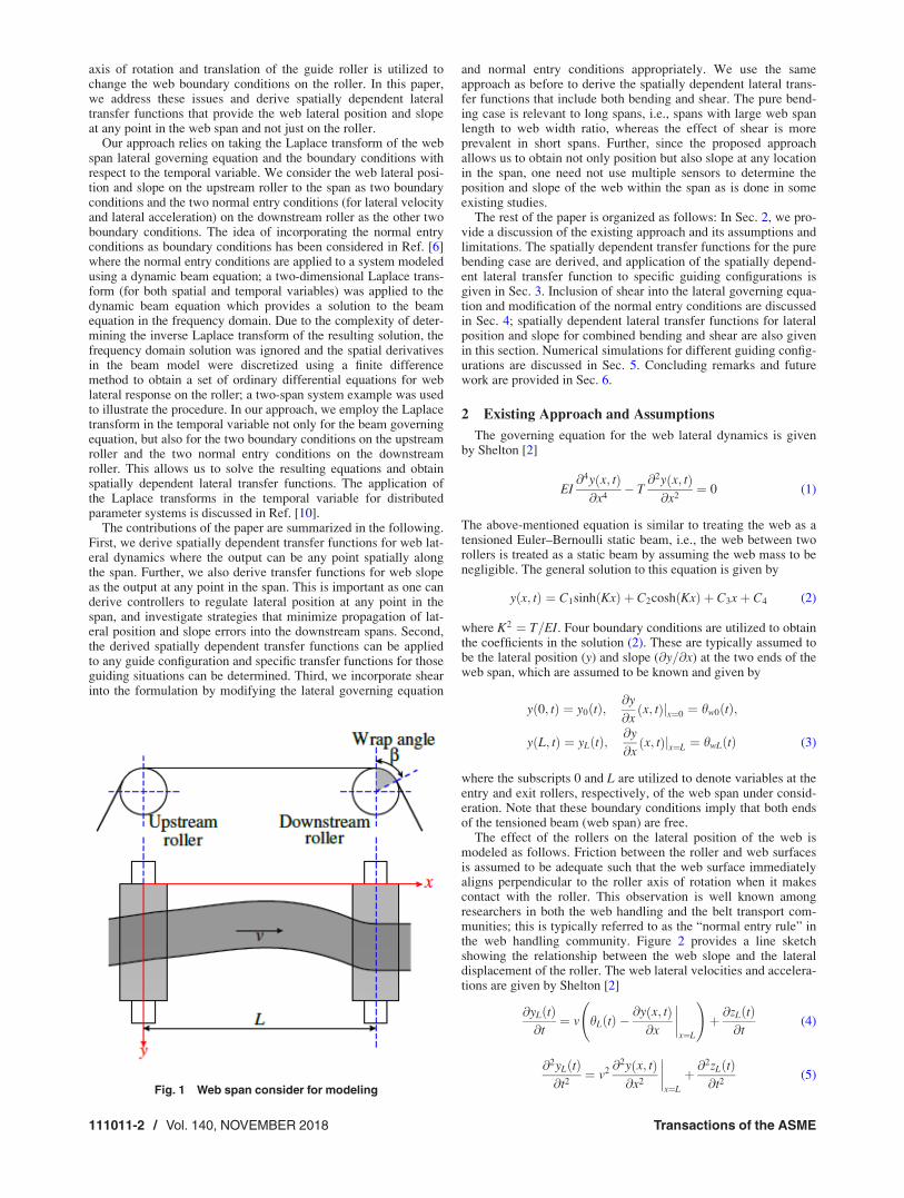


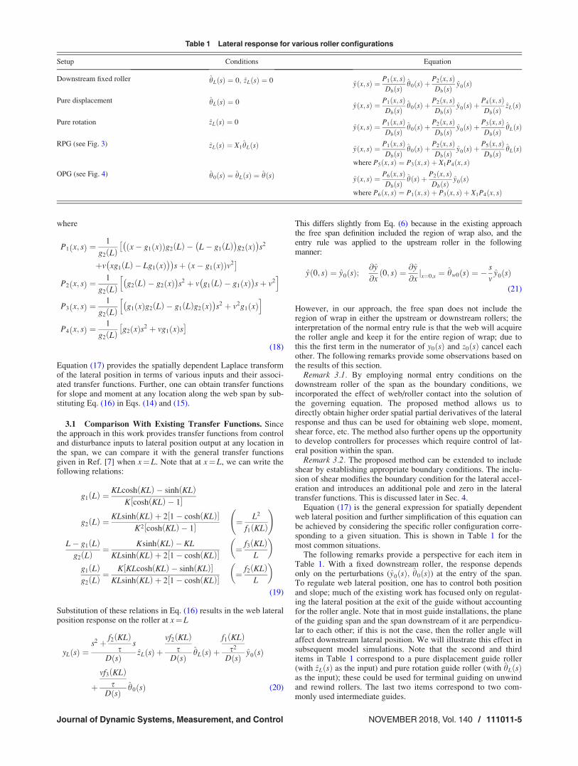


![Polynomial Chaos Expansions for Random Ordinary ...sites.science.oregonstate.edu/~gibsonn/Teaching/...spatially dependent soil properties [4]. Another example is the propagation ...](https://static.documents.pub/doc/80x56/5f39c6e7dd19362eb863bb84/polynomial-chaos-expansions-for-random-ordinary-sites-gibsonnteaching-spatially.jpg)


![Global sensitivity analysis for models with spatially ... · arXiv:0911.1189v4 [stat.CO] 23 Sep 2010 Global sensitivity analysis for models with spatially dependent outputs Amandine](https://static.documents.pub/doc/80x56/5f471def4a5b5d0ce34cea64/global-sensitivity-analysis-for-models-with-spatially-arxiv09111189v4-statco.jpg)


