1602 J. Opt. Soc. Am. B / Vol. 12, No. 9 / September 1995 Beli´ c et al. Spatiotemporal effects in double phase conjugation M. R. Beli´ c Institute of Applied Physics – Nonlinear Dynamics, Technical University Darmstadt, Hochschulstrasse 4a, 64289 Darmstadt, Germany, and Institute of Physics, P.O. Box 57, 11001 Belgrade, Yugoslavia J. Leonardy Institute of Applied Physics – Nonlinear Dynamics, Technical University Darmstadt, Hochschulstrasse 4a, 64289 Darmstadt, Germany D. Timotijevi´ c Institute of Physics, P.O. Box 57, 11001 Belgrade, Yugoslavia F. Kaiser Institute of Applied Physics – Nonlinear Dynamics, Technical University Darmstadt, Hochschulstrasse 4a, 64289 Darmstadt, Germany Received July 25, 1994; revised manuscript received April 4, 1995 Spatial and temporal effects arising in photorefractive crystals during the process of double phase conjugation are analyzed numerically with a novel beam-propagation method. Slowly varying envelope wave equations in the paraxial approximation are solved under the appropriate boundary conditions. Our analysis includes dynamical effects caused by the buildup of diffraction gratings in the crystal and the turn-on of phase-conjugate beams as well as spatial effects caused by the finite transverse spread of beams and by the propagation directions of the beams. Various phenomena are observed, such as self-bending of phase-conjugate beams, convective flow of energy out of the interaction region, mode oscillations, critical slowing down at the oscillation threshold, and irregular spatial pattern formation. For a real beam-coupling constant and constructive interaction of interference fringes in the crystal we find steady or periodic behavior. For a complex coupling constant and /or induced phase mismatch in the grating a transition to spatiotemporal chaos is observed. We believe that under stable operating conditions the transverse double phase-conjugate mirror in the paraxial approximation is a convective oscillator, rather than an amplifier. Improved agreement with experimental results is obtained. 1. INTRODUCTION Double phase conjugation (DPC) was shrouded in con- troversy almost from its conception. It is an interesting wave mixing process in which two laser beams illuminate a photorefractive (PR) crystal incoherently, causing the appearance of two counterpropagating phase-conjugate beams (Fig. 1). DPC was suggested and first demon- strated by Cronin – Golomb et al. 1 but was deemed im- probable by the same group, because of the competing conical emission. Indeed, the initial demonstration was achieved with the use of additional mirrors. It took a few years for Fischer and his colleagues 2 to demonstrate DPC in its pure form, two beams plus a crystal. What made this possible is the preferential amplification of both conjugate beams by a particular set of fanning gratings. A more recent controversy involving DPC is connected with the question whether DPC is a self-oscillation process or an optical amplification process. The differ- ence between the two is subtle in numerical simulations as well as in experiment. It amounts to whether a fi- nite phase conjugate (PC) output can be obtained from zero (i.e., infinitesimal) input or whether a finite input is always needed. Oscillation requires a fast (exponen- tial) growth rate above threshold and a feedback mech- anism. In the plane-wave (PW) case it is agreed that DPC is an oscillation. 2 In the spatial case with one or two transverse dimensions this is not clear. The analy- sis of Ref. 3, based on a linear, undepleted-pumps theory, indicates that DPCM is a convective amplifier. This was confirmed experimentally by the same group for arbi- trary large angles between the interacting beams. 4 A more recent and more comprehensive analysis of a simi- lar theory 5 (including depletion and diffraction) reaffirms that conclusion. Another transverse model 6 based on a PW expansion claims that the double phase-conjugate mirror (DPCM) is still an oscillator. The theory pre- sented in Ref. 7 uses the vectorial nature of coupled-wave equations to show that the DPCM is an oscillator. Among other things, we try to elucidate this contro- versy. However, this is not the central theme of this pa- per. In general, we want to understand the operation of a DPCM and to study its spatiotemporal behavior. A convenient starting point for such a program is the wave equations describing four-wave mixing (4WM) processes in the paraxial approximation: 0740-3224/95/091602-15$06.00 1995 Optical Society of America
Transcript
1602 J. Opt. Soc. Am. B/Vol. 12, No. 9 /September 1995 Belic et al.
Spatiotemporal effects in double phase conjugation
M. R. Belic
Institute of Applied Physics–Nonlinear Dynamics, Technical University Darmstadt, Hochschulstrasse 4a,64289 Darmstadt, Germany, and Institute of Physics, P.O. Box 57, 11001 Belgrade, Yugoslavia
J. Leonardy
Institute of Applied Physics–Nonlinear Dynamics, Technical University Darmstadt,Hochschulstrasse 4a, 64289 Darmstadt, Germany
D. Timotijevic
Institute of Physics, P.O. Box 57, 11001 Belgrade, Yugoslavia
F. Kaiser
Institute of Applied Physics–Nonlinear Dynamics, Technical University Darmstadt,Hochschulstrasse 4a, 64289 Darmstadt, Germany
Received July 25, 1994; revised manuscript received April 4, 1995
Spatial and temporal effects arising in photorefractive crystals during the process of double phase conjugationare analyzed numerically with a novel beam-propagation method. Slowly varying envelope wave equationsin the paraxial approximation are solved under the appropriate boundary conditions. Our analysis includesdynamical effects caused by the buildup of diffraction gratings in the crystal and the turn-on of phase-conjugatebeams as well as spatial effects caused by the finite transverse spread of beams and by the propagationdirections of the beams. Various phenomena are observed, such as self-bending of phase-conjugate beams,convective flow of energy out of the interaction region, mode oscillations, critical slowing down at the oscillationthreshold, and irregular spatial pattern formation. For a real beam-coupling constant and constructiveinteraction of interference fringes in the crystal we find steady or periodic behavior. For a complex couplingconstant and/or induced phase mismatch in the grating a transition to spatiotemporal chaos is observed. Webelieve that under stable operating conditions the transverse double phase-conjugate mirror in the paraxialapproximation is a convective oscillator, rather than an amplifier. Improved agreement with experimentalresults is obtained.
1. INTRODUCTION
Double phase conjugation (DPC) was shrouded in con-troversy almost from its conception. It is an interestingwave mixing process in which two laser beams illuminatea photorefractive (PR) crystal incoherently, causing theappearance of two counterpropagating phase-conjugatebeams (Fig. 1). DPC was suggested and first demon-strated by Cronin–Golomb et al.1 but was deemed im-probable by the same group, because of the competingconical emission. Indeed, the initial demonstration wasachieved with the use of additional mirrors. It took afew years for Fischer and his colleagues2 to demonstrateDPC in its pure form, two beams plus a crystal. Whatmade this possible is the preferential amplification of bothconjugate beams by a particular set of fanning gratings.
A more recent controversy involving DPC is connectedwith the question whether DPC is a self-oscillationprocess or an optical amplification process. The differ-ence between the two is subtle in numerical simulationsas well as in experiment. It amounts to whether a fi-nite phase conjugate (PC) output can be obtained fromzero (i.e., infinitesimal) input or whether a finite input
0740-3224/95/091602-15$06.00
is always needed. Oscillation requires a fast (exponen-tial) growth rate above threshold and a feedback mech-anism. In the plane-wave (PW) case it is agreed thatDPC is an oscillation.2 In the spatial case with one ortwo transverse dimensions this is not clear. The analy-sis of Ref. 3, based on a linear, undepleted-pumps theory,indicates that DPCM is a convective amplifier. This wasconfirmed experimentally by the same group for arbi-trary large angles between the interacting beams.4 Amore recent and more comprehensive analysis of a simi-lar theory5 (including depletion and diffraction) reaffirmsthat conclusion. Another transverse model6 based on aPW expansion claims that the double phase-conjugatemirror (DPCM) is still an oscillator. The theory pre-sented in Ref. 7 uses the vectorial nature of coupled-waveequations to show that the DPCM is an oscillator.
Among other things, we try to elucidate this contro-versy. However, this is not the central theme of this pa-per. In general, we want to understand the operationof a DPCM and to study its spatiotemporal behavior. Aconvenient starting point for such a program is the waveequations describing four-wave mixing (4WM) processesin the paraxial approximation:
1995 Optical Society of America
Belic et al. Vol. 12, No. 9 /September 1995 /J. Opt. Soc. Am. B 1603
Fig. 1. DPCM. Pump beams A2 and A4 enter the crystal fromopposite sides. A1 is the PC of A2, and A3 the PC of A4. z is thepropagation direction and x is one of the transverse directions,the other, y, being perpendicular to the x–z plane. Q representsthe amplitude of the transmission grating. V is the high-voltagesource of the electric field E0 (see Section 5).
≠zA1 1 bK ? =T A1 1 if=T2A1 QA4 , (1a)
≠zA2 1 bK ? =T A2 2 if=T2A2 QA3 , (1b)
≠zA3 2 bK ? =T A3 2 if=T2A3 2QA2 , (1c)
≠zA4 2 bK ? =T A4 1 if=T2A4 2QA1 , (1d)
where Aj sx, y, zd are the slowly varying envelopes ofthe four beams, b is the relative transverse displace-ment (caused by the noncollinear propagation of the fourbeams), and f is the parameter controlling the diffractionin the crystal. In scaled coordinates b uy
p2 d, where u
is the half-angle at the beam intersection and d is the an-gular spread of the interacting beams. f is proportionalto the inverse of the Fresnel number: f s4pF d21.K ? =T is the directional derivative in the transverse sx, ydplane along the grating wave vector K, and =T
2 DT isthe transverse Laplacian. The bar denotes complex con-jugation, and Q is the amplitude of the grating that is gen-erated in the crystal. The x and y axes are arranged sothat the wave vector of the grating points along the y xdirection. Equations (1) are derived in Appendix A.
To these equations one must specify boundary condi-tions. The conditions are that the four initial ampli-tudes C124 be launched into the crystal, as in Fig. 1. Thetransverse amplitude profiles are assumed to be displacedGaussians, with parameters that take into account non-collinear propagation of the beams:
A4,1sx, y, 0d C4,1Gs2z , rd ,
A2,3sx, y, dd C2,3Gsz , rd , (2)
where z 0 and z d 1 denote the entry and theexit faces of the crystal, respectively, and Gsz , rd is theGaussian beam function:
Gsz , rd
exp
(i
"tan21sz d 2
r2
z 1 z 21
#2
r2
1 1 z 2
)p
1 1 z 2. (3)
Here z 4jyF , where j is the beam curvatureparameter8 and F is the Fresnel number. r2 fsx 6
by2d2 1 sy 6 by2d2gys2, where s is the stretching factorthat keeps the transverse computational space between
21 and 11. In DPC the initial PC beams C1 and C3
are not supplied externally; they arise from the noisein the crystal. Therefore we set C1 and C3 very smallcompared with the pumps C2 and C4 (in general smallerthan 1024).
The temporal evolution of Q is approximated by a re-laxation equation of the form
t≠tQ 1 hQ G
IsA1A4 1 A2A3d , (4)
where t is the relaxation time of the grating, h is a di-mensionless parameter dependent on the ratio of internalelectric fields of the PR crystal, I is the total intensity, andG is the PR coupling strength (coupling constant times thecrystal thickness). Both G and b can be positive or nega-tive; however, we consider only the positive values. Thewaves are following the changes in the crystal adiabati-cally; therefore the temporal derivatives in Eqs. (1) areignored. Likewise, the spatial derivatives are neglectedin Eq. (4), because the diffusion effects are controlled bythe slow electronic processes in PR crystals.
Not many researchers were concerned with trans-verse and dynamical effects in PR oscillators.9 Apartfrom the Russian and American groups cited above,3 – 6
Liu and Indebetouw11 expressed interest in the dynam-ics of vortices in PR cavities. They employed off-Braggwave-number mismatch as a means of destabilizing theintracavity oscillation. Another way to destabilize theintracavity field is to apply an external electric fieldacross the crystal, whereby the coupling constant is madecomplex.12 We use this method to drive the system tospatiotemporal chaos.
Numerical solution of 4WM problems including trans-verse and dynamical effects is beyond the reach ofpresent-day computers. To our knowledge this has notbeen attempted in its full complexity. An approximatemethod based on a truncated modal decomposition is em-ployed in Ref. 11. The authors decomposed an intracav-ity field into a small number of Gauss–Hermite modes,hoping to capture the dynamics of modes in the crystalby a limited set of eigenmodes of the empty cavity. Notmore than qualitative agreement with experiment canbe expected from such a method, especially if there areinstabilities and chaos in the system.
Another transverse model, two-wave mixing with trun-cated PW decomposition, is used to describe PR backscat-tering, soliton propagation, and DPC.6 The treatment isrestricted to one transverse dimension. Similar in spiritto our method is the whole-beam method presented byCronin-Golomb and Ratnam and Banerjee.10 All the in-teracting beams in that method are treated as one com-bined beam interacting with itself in the crystal. Themethod is applied to two-wave mixing in steady state andin one transverse dimension.
We present a novel numerical procedure that isbased on the thin gain sheets beam-propagation method(BPM).13 The method was used originally for mode cal-culations in high-power lasers, and here it is modified tohandle wave mixing in PR crystals. Such mixing permitsadiabatic separation of the spatial mode problem in thecrystal from the slow temporal problem of the buildup ofgratings. This makes the numerical problem tractable.
1604 J. Opt. Soc. Am. B/Vol. 12, No. 9 /September 1995 Belic et al.
Fig. 2. Self-consistency parameter a as a function of the cou-pling strength G. Solid curves are the numerical solutions ofEq. (B6); dashed curves are the approximate solutions, Eq. (B7).Curves AA and BB are the simple PC curves, with the boundaryconditions jC1j2 jC2j2 1, jC3j2 0, and jC4j2 0.7 for theAA and jC4j2 0.4 for the BB curves. Curve CC is the 4WMcurve, with the conditions jC1j2 0.4, jC2j2 1, jC3j2 0.1, andjC4j2 1. Curve D is the DPC threshold curve, Eq. (7), withthe conditions jC2j2 1, jC4j2 0.1 (arbitrary units).
However, instead of treating all interacting beams asone whole beam, or making PW or other truncated de-compositions of beams, we retain the individuality ofall four beams. We perform mostly three-dimensionalsimulations and include temporal variations. The pro-cedure is checked in parts and as a whole on analyticaland numerical PW results, to yield good agreement. Intreating transverse effects we concentrate on the influ-ence of diffraction because the effects of noncollinearityhave been thoroughly investigated by others.3 In treat-ing dynamical effects we concentrate on the behavior thatleads to instabilities and spatiotemporal chaos.
This paper is organized as follows. Section 2 presentsthe PW theory of DPC. A numerical method for solutionof Eqs. (1) and (4) is presented in Section 3. Section 4deals with the spatial aspects of the generation and propa-gation of PC beams in the crystal. Section 5 is concernedwith the dynamical effects connected with DPC, includ-ing spatiotemporal instabilities. Section 6 provides dis-cussion and offers some conclusions.
2. PLANE-WAVE THEORYAnalytical treatment of Eqs. (1) and (4) is not possible.Equations without diffraction sf 0d have been con-sidered in Ref. 3. Steady-state PW absorptionless 4WMequations were first considered by Cronin-Golomb et al.1
The case of real coupling constants was treated in Ref. 14.We follow that method. The solution procedure is out-lined in Appendix B.
For DPC boundary conditions are simplified, in thatC1 0 and C3 0. This leads to a simplification inthe solution procedure of Appendix B. The exit PC fields[from Eqs. (B2)] are given by
A30 C2 sinsud , A1d C4 sinsud , (5)
where u Qd 2 Q0 is the total grating action. Theboundary values Q0 at z 0 and Qd at z d of the inde-pendent variable Qszd from Appendix B are given by
tansQ0d exp
√2
aG
2
!√a 2 qp
a 1 qp
!1/2
,
tansQdd exp
√aG
2
!√a 2 qp
a 1 qp
!1/2
, (6)
where qp sjC4j2 2 jC2j2dysjC4j2 1 jC2j2d is the ratio of theinput power flux to the total input intensity. The self-consistency parameter a is found from the transcendentalequation
a tanhsaGy2d . (7)
This is an important parameter in the theory. It definesthe threshold for oscillation. A sample of values for dif-ferent wave mixing processes is depicted in Fig. 2. The
(a)
(b)Fig. 3. Checking the numerics: comparison with PW solu-tions (curves, analytical results; squares, numerical results).Four fields inside the crystal are shown as functions of thelongitudinal spatial variable z. (a) dz 0.01, (b) dz 0.005.In the following computations dz is kept fixed at 0.005.The other parameters are b 0, G 5, h 1, jC2j2 0.1,jC4j2 1, jC1j2 ejC4j2, jC3j2 ejC2j2, and e 1029. Lineardependence of the numerical error on dz is evident.
Belic et al. Vol. 12, No. 9 /September 1995 /J. Opt. Soc. Am. B 1605
threshold condition on the coupling strength Gth 2 isobtained from Eq. (7).
Thus for DPC the transmissivity of the crystal in bothdirections is the same, Td T0 T sin2sud. We usethis conclusion and the solution above to check our nu-merical procedure. As will be seen below, the equality oftransmissivities does not hold in the transverse case, ow-ing to the nonreciprocity of the scattering in PR crystals.It is interesting to note that by using the same method onecan prove that DPC with reflection-type gratings QR A1A3 1 A2A4 is not possible. More precisely, DPCM withreflection-type gratings will not oscillate (however, it mayamplify the finite beam seeds of C1 and C4).
3. INTEGRATION METHODThe problem with the integration of Eqs. (1) and (4) liesin the nature of PR coupling and the split boundary con-ditions that have to be satisfied at the opposite faces ofthe crystal. We will attempt to accomplish integrationwithin slight, but reasonable, approximations. The de-tails of our algorithm are presented in Appendix C.
The spatial propagation problem of Eqs. (1) is ad-dressed by a modified spectral BPM13 used for modecalculations in bare or loaded unstable resonators. Asolution of Eq. (4) is found by a Runge–Kutta or anotherinitial-value algorithm. The procedure is facilitated bythe fact that the temporal derivatives are neglected inEqs. (1) and the spatial derivatives are neglected inEq. (4). Thus the spatial integration can be separatedfrom and nested within the temporal integration loop.
The thin gain sheets BPM could be applied directly toEqs. (1) if the right-hand side of the jth beam equationwere of the form msI dAj . However, this is not the case,and we modify the procedure to accommodate the newform, keeping the spirit of the BPM alive. We use thefact that the spatial equations are naturally paired intotwo sets, with two pairs of copropagating fields. Thus weconcurrently propagate the pair sA1, A4d to the right andthe pair sA2, A3d to the left, constantly modifying them forthe coupling Q in an iterative self-consistent procedure.After the fields have converged into a quasi-stationarystate corresponding to a given Q, the temporal evolutionfor a time step is performed.
Another problem is the geometry of beam coupling, withthe two counterpropagating pairs of beams contributingto Q. As the source of coupling in the spatial domainis the grating amplitude Q (proportional to the space-charge field in the crystal), it must be known at eachinstant of time at all locations in the crystal. Likewisefor the total intensity I, which figures explicitly in Eq. (4)(and is not an integration constant in the time-dependenttransverse case). This makes stringent requirements onthe computer core space.
In the PW case sb f 0d we find good agreement be-tween the numerical and the analytical solutions (Fig. 3).If transverse effects are included and Gaussian inputbeams are used, the intensities of the PC beams sI1, I3ddecrease compared with those in the PW case. The inclu-sion of diffraction is always detrimental to the process ofDPC. Likewise, the inclusion of absorption is also detri-mental to the process of DPC.
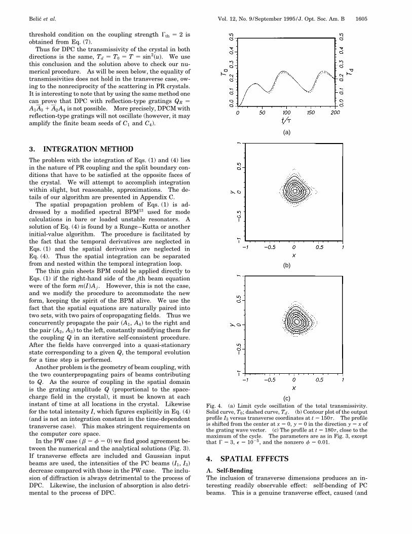
(a)
(b)
(c)Fig. 4. (a) Limit cycle oscillation of the total transmissivity.Solid curve, T0; dashed curve, Td. (b) Contour plot of the outputprofile I3 versus transverse coordinates at t 150t. The profileis shifted from the center at x 0, y 0 in the direction y x ofthe grating wave vector. (c) The profile at t 180t, close to themaximum of the cycle. The parameters are as in Fig. 3, exceptthat G 3, e 1025, and the nonzero f 0.01.
4. SPATIAL EFFECTS
A. Self-BendingThe inclusion of transverse dimensions produces an in-teresting readily observable effect: self-bending of PCbeams. This is a genuine transverse effect, caused (and
1606 J. Opt. Soc. Am. B/Vol. 12, No. 9 /September 1995 Belic et al.
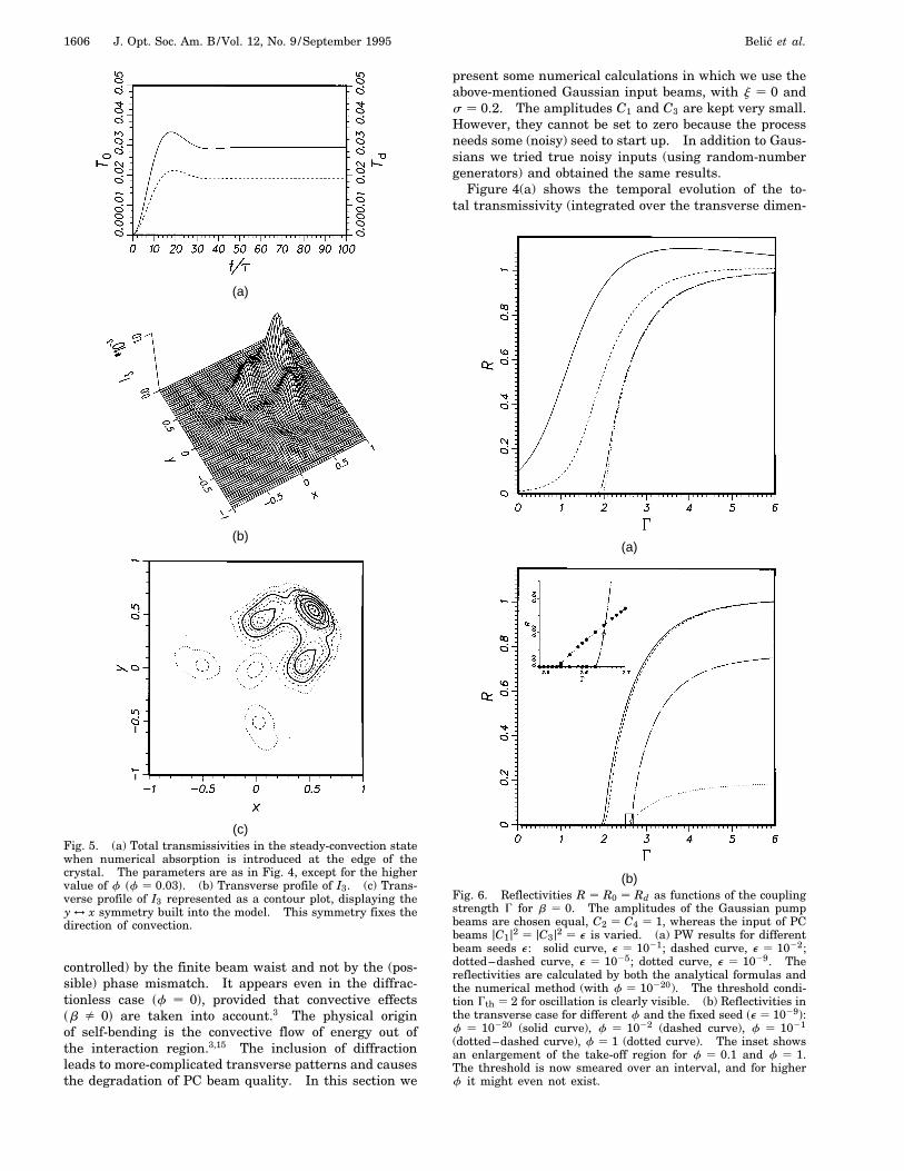
(a)
(b)
(c)Fig. 5. (a) Total transmissivities in the steady-convection statewhen numerical absorption is introduced at the edge of thecrystal. The parameters are as in Fig. 4, except for the highervalue of f sf 0.03d. (b) Transverse profile of I3. (c) Trans-verse profile of I3 represented as a contour plot, displaying they $ x symmetry built into the model. This symmetry fixes thedirection of convection.
controlled) by the finite beam waist and not by the (pos-sible) phase mismatch. It appears even in the diffrac-tionless case sf 0d, provided that convective effectssb fi 0d are taken into account.3 The physical originof self-bending is the convective flow of energy out ofthe interaction region.3,15 The inclusion of diffractionleads to more-complicated transverse patterns and causesthe degradation of PC beam quality. In this section we
present some numerical calculations in which we use theabove-mentioned Gaussian input beams, with j 0 ands 0.2. The amplitudes C1 and C3 are kept very small.However, they cannot be set to zero because the processneeds some (noisy) seed to start up. In addition to Gaus-sians we tried true noisy inputs (using random-numbergenerators) and obtained the same results.
Figure 4(a) shows the temporal evolution of the to-tal transmissivity (integrated over the transverse dimen-
(a)
(b)Fig. 6. Reflectivities R R0 Rd as functions of the couplingstrength G for b 0. The amplitudes of the Gaussian pumpbeams are chosen equal, C2 C4 1, whereas the input of PCbeams jC1j2 jC3j2 e is varied. (a) PW results for differentbeam seeds e: solid curve, e 1021; dashed curve, e 1022;dotted–dashed curve, e 1025; dotted curve, e 1029. Thereflectivities are calculated by both the analytical formulas andthe numerical method (with f 10220). The threshold condi-tion Gth 2 for oscillation is clearly visible. (b) Reflectivities inthe transverse case for different f and the fixed seed se 1029d:f 10220 (solid curve), f 1022 (dashed curve), f 1021
(dotted–dashed curve), f 1 (dotted curve). The inset showsan enlargement of the take-off region for f 0.1 and f 1.The threshold is now smeared over an interval, and for higherf it might even not exist.
Belic et al. Vol. 12, No. 9 /September 1995 /J. Opt. Soc. Am. B 1607
sions) at both faces of the crystal. In the transverse caseT0 fi Td. However, the analytical PW formulas R0 T0yr and Rd rTd (where r is the ratio of input inten-sities, r jC4yC2j2) are still valid. Figures 4(b) and 4(c)depict the tilt of the beam I3 away from the center x 0,y 0 of the transverse plane at z 0. The transversedistribution of the beam represents a breathing-deformedGaussian mode. Breathing in this context means a pe-riodic change of the transverse intensity pattern from aminimum to a maximum. The performed Gaussian modeis symmetric with respect to the y x axis. It keeps theprescribed symmetry in force. We assume that in thiscase the regular shift is caused by nonequal values forthe input seeds of the PC beams.
If the influence of diffraction in increased (higher val-ues of f), a state of steady convection is reached, withfurther spatial widening of the PC beam and the appear-ance of local maxima in the beam profile (Fig. 5). Thedrift of the output profile away from the center is morepronounced, but eventually it is controlled by the physicalsize of the crystal or by some other nonlinear loss mecha-nism. In the simulations we damp the fields at the edgeof the numerical grid. The drift of interacting fields inthe crystal (or the domains of interaction) to the side ofincident pumps is observed experimentally.4,16
Our results agree with the recent research on two-dimensional DPCM’s3 only when directional effects areincluded and diffraction excluded, and even then onlyqualitatively. We conclude that a DPCM with diffractionis a convective oscillator. However, for strong diffrac-tion and strong couplings more-complicated spatiotem-poral phenomena are observed. The reasons for thediscrepancy are probably that the theory in Ref. 3 is lin-ear (it applies to low-reflectivity levels), in the numericalresults diffraction is neglected, and the theory is derivedfor a rather special two-dimensional geometry. It doesnot contain transverse Laplacian.
B. Oscillation versus AmplificationThe convective flow of energy helps to resolve the contro-versy between oscillation and amplification. The authorsof Ref. 3 believe that the transport of energy is the mecha-
nism for inhibition of oscillation. In the PW case such amechanism is absent.
We believe that, in addition to convection, an importantmechanism is the multimode operation of DPCM whentransverse dimensions are accounted for. The Fresnelnumber F determines the maximum number of trans-verse modes that can oscillate.17 In general, the num-ber of possible transverse modes scales as F 2. Whichtransverse modes oscillate depends on the boundary con-ditions, coupling strength, and other details of the ex-perimental setup. Different spatial modes have differentoscillation thresholds. In the transverse case there is noprecise threshold condition for oscillation. When morethan one mode can oscillate, the oscillation does not startat a particular value of coupling but is turned on gradu-ally over an interval. A more realistic transverse modelchanges the sharp steplike transition at the threshold intoa more gradual continuous transition, with finite (thoughlarge) derivatives. This is clearly visible in Fig. 6, whichdepicts the amplification of different beam seeds for thesame value of f sf 10220d and the amplification of thesame seed sjC1j2 jC3j2 e 1029d for different f. Theinterval of threshold conditions is seen in Fig. 6(b).
Figure 7 represents the amplification of different seedsfor different values of f on the logarithmic scale. Theshift toward larger couplings and a less steep rise is vis-ible. Figures 6 and 7 are obtained for b 0. In gen-eral, b 0 does not mean that the beams are actuallycollinear. It means that the ratio of the angle at thebeams’ intersection to the angular spread of the beamsis small and hence neglected. The figures also displayhow subtle these effects are when investigated numeri-cally. Qualitatively, different cases look similar. How-ever, the existence of an oscillation threshold is evidentin all the cases. As the threshold is approached, criticalslowing down is observed. For small e it takes long timesto achieve convergence. Below threshold the device actsas an amplifier; above threshold it is an oscillator. Also,the appearance of convection is evident when transversedimensions are accounted for. Having to choose betweena convective amplifier and an optical oscillator in describ-ing a DPCM, we believe that the appropriate choice is aconvective oscillator.
Fig. 7. Reflectivities versus coupling strength onthe logarithmic scale for different seeds e. Theexistence of an oscillation threshold as e goes tozero is evident. Below the threshold DPCM is anamplifier; above the threshold the saturation of re-flectivities is noted. The shift of the threshold andthe reduction of derivatives are shown for three val-ues of f f : squares, e 1021; circles, e 1022;triangles, e 1025; crosses, e 1029. The curvesare polynomial fits through the points, drawn toguide the eye.
1608 J. Opt. Soc. Am. B/Vol. 12, No. 9 /September 1995 Belic et al.
Fig. 8. Dynamics of the oscillationswitch on, for two values of the transversedisplacement b and for different valuesof the coupling strength G. Total reflec-tivities are presented as functions of timefor different values of the seed e (solidcurves, e 1021; dashed curves, e 1022;dotted–dashed curves, e 1025; dottedcurves, e 1029). For (a)–(c) b 0.1,and the device acts as an amplifier. For(d)–(f ) b 0.01, and the device acts as anoscillator. In (a) (when the whole curvefor e 1029 is multiplied by 50) and (d)G 3, in (b) and (e) G 4, and in (c) and(f ) G 5. Here f 0.
(a) (c)
(b) (d)Fig. 9. Transverse profiles of the beam I30 for f 0 and e 1025 and for different values of the coupling strength G and of thetransverse displacement b: (a) G 3, (b) G 5. The value of b is given in each figure. The dashed curves are profiles of one ofthe pumps (for b 0.1). (c) Spatial transverse distribution of beams I2 and I3 in the crystal for b 0.2 and G 5. A small amountof seed se 1025d and of diffraction sf 2.72 3 1024d is included. (d) Same as (c) for the total intensity.
Belic et al. Vol. 12, No. 9 /September 1995 /J. Opt. Soc. Am. B 1609
An emerging physical picture concerning amplificationand oscillation is as follows. For f 0 and b 0 theDPCM is an oscillator. For f fi 0 and b 0 it is a con-vective oscillator. For f 0 and b fi 0 it is an oscillatorup to a critical transverse displacement bc. Above bc itis a convective amplifier.3 For f fi 0 and b fi 0 the situ-ation is not so clear. There seems to exist a critical curvein the sb, fd plane below which the device acts as a con-vective oscillator and above which it acts as a convectiveamplifier. Owing to critical slowing down, the investiga-tion of such a critical curve is computationally expensive.
Figure 8 shows the influence of b for f 0. Two val-
ues of b are chosen, one well below the critical value bc
and the other well above the critical value. The valueof the critical transverse displacement depends on thecoupling strength. Figure 9 presents transverse profilesof the PC beam I30 for different values of the couplingstrength and of the transverse displacement. Also rep-resented is the transverse distribution of beams in thecrystal during the DPC process [Figs. 9(c) and 9(d)].
C. Transverse PatternsThe inclusion of transverse dimensions leads to richspatial and temporal phenomena.10,17 Here we present
(a)
(b) (c)Fig. 10. (a) Dynamics of the total transmissivities T T0 Td for f 0.05 and G 3. (b) Contour plot of the transverse profileof I3 close to the cycle minimum at t 215t. (c) Contour plot at the cycle maximum, t 240t.
(a) (c)
(b) (d)Fig. 11. Transverse patterns of the PC field I3 at four locations during one cycle in Fig. 10. (a) t 200t, (b) t 205t, (c) t 215t,(d) t 240t. A periodic rise of the convective pulse is observed. The pulse is absorbed at the edge of the crystal.
1610 J. Opt. Soc. Am. B/Vol. 12, No. 9 /September 1995 Belic et al.
Fig. 12. Comparison with the experimental results of Ref. 2:(a) Reflectivities R0 and Rd at both sides of the crystal asfunctions of the pump ratio r. Filled circles are the experimentalvalues of R0, and crossed circles are the values of Rd. Dashedcurves are polynomial fits through the experimental points.Solid curves are numerical curves with G 4 and f 0.121.(b) Corresponding transmissivities T0 and Td. One of the solidcurves is a fourth-order polynomial fit through the experimentalpoints for T0, and the other is the corresponding numerical curve.Dashed curves are the same for Td .
a periodic solution (limit cycle) with a more-complicatedtransverse structure. A limit cycle is a periodic solutionthat sets up after one Hopf bifurcation in the system.In this context it is a solution with constant intensity ofany beam and with the phases circling clockwise or coun-terclockwise in time. It is difficult to speak of phaseconjugation now, because the output profile I3 bears lit-tle resemblance to the input profile I4. The differencefrom the previous example of convection (Fig. 5) lies inthe higher value of the f parameter and in the equalinput pumps sC2 C4 1d. However, the Fresnel num-ber is still large enough to permit the excitation of morethan one spatial mode. Figure 10 shows the temporalevolution of the total transmissivity T and the contourplots of the transverse beam profiles at approximately theminimum and the maximum of the limit cycle oscillation.Figure 11 depicts consecutive snapshots of the transverseprofiles at four instants during one cycle. The dynamicsof the cycle proceeds from a weak but complicated pro-file at the minimum to a strong convective pulse at themaximum. The pulse gets absorbed at the grid edge,with the consequent loss of energy, and the cycle repeats.Such behavior is characteristic of a spatially and tempo-rally ordered state. We did not observe chaos, neithertemporal nor spatiotemporal, as long as the couplingconstant remained real. This agrees with the conclu-
sions of an earlier report11 on chaos in single-gratingsingle-interaction-region 4WM. However, that report isconcerned with a PW model.
D. Comparison with ExperimentThe inclusion of transverse effects improves the agree-ment between numerical and experimental results. Thetheory based on PW analysis consistently gives too highestimates for the intensity reflectivity.2 Figure 12 offersa comparison between numerical and experimental re-sults. The only fitting parameter here is the value of f.For f 0.121 a good agreement for R0 and Rd is found.A more improved agreement could easily be obtainedby inclusion of linear absorption and/or noncollinearity.However, we prefer the figure as is, as it clearly dis-plays another tiny but important transverse effect: non-reciprocity. That is, the transmissivities at the 0 faceand at the d face of the crystal in the transverse caseare not equal because the scattering off PR gratings isnonreciprocal.
5. DYNAMICAL EFFECTSAnalysis of stable patterns that can set up in PR oscilla-tors is the first step in an investigation of spatiotemporalinstabilities and the road to chaos through the generationand dynamics of structural defects.10,17
(a)
(b)Fig. 13. Temporal signal for an ordered PW state with theexternal electric field applied transversely across the crystal(along the x direction). (a) Transmissivities, (b) phase portraitof the lower, stable state, showing that indeed it is a limit cycle.The parameters are jC1j2 jC3j2 1025, jC2j2 jC4j2 1,G0 4, f 10220, EM 100, Eq 5, ED 1, and E0 4(arbitrary units).
Belic et al. Vol. 12, No. 9 /September 1995 /J. Opt. Soc. Am. B 1611
Fig. 14. Temporal behavior with the inclusion of transverseeffects. Left column, transmissivity T T0 Td; right column,phase portrait of A3 (at z 0) in the center of the beam after1000t steps. The same parameters as in Fig. 13, except for (a)f 0.006, (b) f 0.003, (c) f 0.002, (d) f 0.001.
We would like to know under what conditions chaoticor turbulent dynamics can arise in our model. As men-tioned, the inclusion of transverse effects does not changeone of the key conclusions of our previous analysis: thelack of chaos for real couplings. Realistic spatiotemporalcomplexity can be introduced in two ways: by applying
an external electric field E0 across the crystal11 and/or byintroducing phase mismatch in the wave interaction.
The first method makes the couplings between thewaves complex,
G G0Eq 1 ED
ED
ED 1 iE0
EM 1 ED 1 iE0
, (8a)
h ED 1 Eq 1 iE0
EM 1 ED 1 iE0
, (8b)
and promotes multimode competition in the crystal18 ow-ing to the presence of external electric field E0; the otherviolates the Bragg condition and introduces competi-tion between the grating-writing interference terms A1A4
and A2A3. Here we investigate only the first method.We further restrict ourselves to an example in whichchaotic behavior is introduced exclusively by the trans-verse spread of beams. For the characteristic internalelectric fields of the PR crystal ED , EM , and Eq we usethe values consistent with the data obtained for bariumtitanate. We also set b 0.
The dynamics of the starting PW state is presented inFig. 13. The system starts to oscillate in the fundamen-tal high-reflectivity mode, which however turns out to beunstable for this high value of the electric field E0. Theinstability grows until the system switches to a stablelow-reflectivity mode.
The situation changes dramatically with the inclusionof transverse dimensions. Figure 14 shows the temporalevolution of the transmissivity T and the phase portraitsof A3 for different values of the diffraction coupling f.T settles onto a fixed value only for large f [Fig. 14(a)].This state becomes unstable for smaller f and oscillatesirregularly [Fig. 14(b)]. The decreasing values of f cor-respond to the increasing values of the Fresnel number.A stationary oscillation is found [Fig. 14(c)], and the finalstate represents another chaotic attractor [Fig. 14(d)].
The overall spatiotemporal behavior of these states isrepresented in Fig. 15. The stationary state is formed bya beam profile with two local maxima [Fig. 15(a)]. On re-duction of f the left peak is suppressed, and the intensityoscillates irregularly in space and time around the rightpeak [Fig. 15(b)]. On further reduction in f a periodic
(a) (b) (c) (d)Fig. 15. Temporal transverse signal of the field I3sxd after the transients have died away. The parameters are as in Fig. 14.
1612 J. Opt. Soc. Am. B/Vol. 12, No. 9 /September 1995 Belic et al.
(a)
(b)
(c)Fig. 16. Filamented transverse profiles of I3 (solid curves) andI2 (dashed curves) at z 0 at different instants: (a) t 1000t,(b) t 1300t, (c) t 1500t. The simulation corresponds tothat of Figs. 14(d) and 15(d). Note the partial anticorrelationbetween the I3 and the I2 peaks.
spatiotemporal state is reached [Fig. 15(c)], where twointensity peaks oscillate coherently to each other. Thiscoherence is lost in Fig. 15(d), and a final state of spa-tiotemporal chaos is formed in which the dynamics of dif-ferent spatial signals is different. Whereas some vaguetransverse spatial correlation of the signal is visible, tem-porally the signal at any spatial location is chaotic. Thespatial correlation length is reduced in going from thestate in Fig. 15(b) to the state in Fig. 15(d).
Owing to strong diffraction effects the filamentation oftransverse output profiles is noticeable (cf. Fig. 16). Thefilamentation of PC beam A3 occurs as a result of sup-pression of pump beam A2, which by means of the com-plex PR coupling G introduces a self-focusing nonlinearityinto the wave equations. This effect is clearly visible ifone looks at the intensity I3 in the crystal, as shown in
Fig. 17. Different peaks with high intensities occur andfocus during the propagation through the crystal. Thefilamentation of beams becomes stronger for smaller val-ues of the coupling f (not shown here). Depending onthe values of other parameters, the filaments move trans-versely or from standing patterns. With an increasedelectric field, a complicated dynamics of traveling trans-verse waves arises. This is consistent with the expec-tation that more-complex diffraction phenomena shouldoccur for higher (but finite) values of the Fresnel number.The system displays an interesting example of transition
(a)
(b)
(c)Fig. 17. Transverse distribution of the field I3 in the crystalat different times. (a) t 1000t, (b) t 1300t, (c) t 1500t.The simulation corresponds to that of Figs. 14(d) and 15(d).
Belic et al. Vol. 12, No. 9 /September 1995 /J. Opt. Soc. Am. B 1613
to spatiotemporal chaos through mode competition, andwe are in the process of quantifying it.
6. CONCLUSIONSIn summary, we have studied transverse and dynami-cal effects in the DPCM. We find that the inclusion ofthe finite lateral beam extension lowers the reflectivities,bends the beams, and resolves the controversy about thenature of DPC. It also improves the agreement with ex-perimental results and accounts for the experimentallyobserved asymmetry between the transmissivities of thecrystal along the beam incidence.
In numerical simulations one always needs a finite seedfor the process of start up; however, one can obtain usefulinformation from the way in which the system behaves asthe seed is getting smaller. Based on such an informa-tion (and confirmed by theoretical results from Section 2),we conclude that in the PW approximation the DPCM isan oscillator with the gain threshold (Gth 2 for equalpumps). Exponential growth of PC beams is observedabove the threshold for arbitrarily small seeds. Seedsare needed only as an initial push. Reflectivity levelsattained do not depend on the seed, with marked satura-tion owing to the depletion of pumps. Below thresholdthe reflectivity depends directly on the seed, going to zeroas the seed is diminished.
In our transverse model the DPCM is a convective os-cillator rather than an amplifier. The gain threshold isnot well defined. However, the existence of an oscilla-tion threshold for each value of the diffraction parameterf is evident. Again, below the threshold region the de-vice acts as an amplifier; different seeds are amplified todifferent levels. Above the threshold the reflectivities de-pend little on the seed, and the signal persists even in theabsence of the seed. When the influence of transversedisplacement is included, for low values of b the device isan oscillator up to a critical value bc. Above the criticalvalue of the transverse displacement the device becomesa convective amplifier.
With the inclusion of transverse dimensions the inten-sity distributions of PC beams become shifted and asym-metric. The bending of beams is caused by the convectiveflow of energy. Steady convection is observed numeri-cally and is also evident in the experiment.4,16 Also, theconvergence of the transverse model is faster than that ofthe PW model of 4WM.
For strong (real) couplings instabilities are noted, inthat the reflectivity (and transmissivity) does not settleonto any fixed value but oscillates regularly. However,in this case the output profile is complicated, and it isdifficult to speak of phase conjugation.
A rich dynamical behavior including spatiotemporalchaos is observed when a dc electric field is appliedacross the crystal. This makes the PR coupling complex.Then the self-focusing that is due to the nonlinearity is incompetition with the diffraction in the crystal. All theseeffects act destructively toward the process of phaseconjugation. We observe competition between differentspatial modes, traveling transverse waves, and defect-mediated turbulence in our system. Such spatiotempo-ral instabilities are under current investigation.
APPENDIX A: DERIVATION OFPARAXIAL WAVE EQUATIONS FORDOUBLE PHASE CONJUGATIONWe start by writing paraxial wave equations for each ofthe two propagation arms:
≠z00 A1 1i
2kD00
T A1 QA4 , (A1a)
≠z00 A2 2i
2kD00
T A2 QA3 , (A1b)
≠z0 A3 2i
2kD0
T A3 2QA2 , (A1c)
≠z0 A4 1i
2kD0
T A4 2QA1 , (A1d)
where the directions of the wave vectors k4 and k1 de-fine the z0 and z00 axes and D
0T and D
00T are the corre-
sponding transverse Laplacians. We use the same setof symbols hAj , Qj to denote the fields and the gratingamplitude in all the cases. For the moment we con-sider only one transverse dimension and assume that theangle between the propagation arms is small. The equa-tion k 2pn0yl denotes the magnitude of wave vectorjkj j in the medium. A degenerate situation is assumed.One then makes a transformation to the common set ofsx, zd coordinates, where the z axis points halfway be-tween z0 and z00. Equations (A1) become
≠zA1 1 u≠xA1 1i
2ks≠x
2 2 2u≠x≠zdA1 QA4 , (A2a)
≠zA2 1 u≠xA2 2i
2ks≠x
2 2 2u≠x≠zdA2 QA3 , (A2b)
≠zA3 2 u≠xA3 2i
2ks≠x
2 1 2u≠x≠zdA3 2QA2 , (A2c)
≠zA4 2 u≠xA4 1i
2ks≠x
2 1 2u≠x≠zdA4 2QA1 , (A2d)
where u is the (small) half-angle between the incidentbeams. Next, the equations are made dimensionless byintroduction of the characteristic longitudinal length (thecrystal thickness d) and the characteristic transverselength (the beam spot size v0). One obtains
≠zA1 1u
d≠xA1 1 ifs≠x
2 2 2ud≠x≠zdA1 QA4 , (A3a)
≠zA2 1u
d≠xA2 2 ifs≠x
2 2 2ud≠x≠zdA2 QA3 , (A3b)
≠zA3 2u
d≠xA3 2 ifs≠x
2 1 2ud≠x≠zdA3 2QA2 , (A3c)
≠zA4 2u
d≠xA4 1 ifs≠x
2 1 2ud≠x≠zdA4 2QA1 , (A3d)
where d v0yd is the beam’s angular spread and f s4pF d21 is related to the Fresnel number F v0
2yld.Now z and x are dimensionless numerical variables con-fined to an appropriately chosen computational domain.Normally u, d, and f are small, so that the mixed deriva-tive correction to the transverse Laplacian can be ne-glected. However, the convective term involving ≠xAj
1614 J. Opt. Soc. Am. B/Vol. 12, No. 9 /September 1995 Belic et al.
cannot be neglected because the quantity b uyd neednot be small.
The extension to two transverse dimensions is easy.Assuming that the wave vector of the grating K (lying inthe transverse plane) makes an angle c with the x axis,the directional derivative becomes K ? =T cosscd≠x 1
sinscd≠y . We pick c py4 and absorb thep
2 factorinto the b. Likewise the transverse Laplacian becomes≠x
2 1 ≠y2.
One should note that the electric fields formed by useof slowly varying envelopes carry additional phases of theform expsikz0 d and expsikz00 d. On transformation andscaling of the coordinates, the optical phase of variousbeams acquires the form kdsz 6 udxd. This phase takesinto account the noncollinear propagation of two pairs ofbeams. In the spirit of paraxial approximation the sec-ond term in the optical phase can be neglected. However,when instabilities and traveling transverse waves are dis-cussed, the second term must be included in the analysis.
APPENDIX B: PLANE-WAVE SOLUTION OFFOUR-WAVE MIXING EQUATIONSIn the steady state, the expression for Q (with h 1) fromEq. (4) is included in Eqs. (1), with b 0 and f 0, andthe resulting equations are solved as a system of first-order ordinary differential equations. The details of thesolution are provided in Ref. 14.
For G real the system of Eqs. (1) is linearized with thefollowing transformation of the independent variable:
Q0 GjQj
I, (B1)
where the prime denotes the derivative along the propa-gation direction z. The solution is then given by
A1 C1 cossQ 2 Q0d 1 C4 sinsQ 2 Q0d , (B2a)
A4 C4 cossQ 2 Q0d 2 C1 sinsQ 2 Q0d , (B2b)
A3 C3 cossQd 2 Qd 1 C2 sinsQd 2 Qd , (B2c)
A2 C2 cossQd 2 Qd 2 C3 sinsQd 2 Qd , (B2d)
where C1-4 are the given boundary values of the fourfields: A1,4sz 0d C1,4 and A2,3sz dd C2,3. Usingthis solution, one finds an expression for the grating am-plitude:
2jQj aI sins2Qd , (B3)
where a is a constant to be determined from the boundaryconditions. For a transmission grating process the totalintensity I is also constant, I jC1j2 1 jC2j2 1 jC3j2 1
jC4j2, so Eq. (B1) is easily integrated:
tansQd tansQ0dexpsaGzd . (B4)
To obtain a complete solution one must determine Q0
and Qd in terms of boundary values. To this end, us-ing the expressions for jQdj 1 jQ0j and jQdj 2 jQ0j from
Eqs. (B3) and (B4), one forms a system of three algebraicequations (for Qd, Q0, and a). The solution is of the form
tansud q
b 2 v, (B5a)
tanssd qb
wb 2 c, (B5b)
b sinsud aI sinssd , (B5c)
where u Qd 2 Q0, s Qd 1 Q0, q C2C3 1 C1C4 1 c.c.,b aI cothsaGy2d, v jC4j2 2 jC3j2 1 jC2j2 2 jC1j2, w jC4j2 1 jC3j2 2 jC2j2 2 jC1j2, p C2C3 2 C1C4 1 c.c., andc pq 2 wv. The self-consistency requirement on thissolution leads to an equation for a:
b2q2 1 swb 2 cd2 a2I 2fq2 1 sb 2 vd2g . (B6)
Equation (B6) must be solved numerically. However, agood approximate solution is obtained if one notes that ashould lie between 21 and 1. In fact, a 0 is alwaysa (trivial) solution of Eq. (B6). For sufficiently large G
(positive or negative) one obtains a nonzero (positive ornegative) value for a. This defines the coupling strengththreshold for oscillation. Assuming aG to be small, oneobtains b 2IyG and
a 1I
"4I 2q2 1 s2Iw 2 cGd2
sqGd2 1 s2I 2 vGd2
# 1/2
. (B7)
A few numerical and approximate solutions are presentedin Fig. 2. Having found a, tansQd 1 Q0d, and tansQd 2
Q0d, one can easily determine Q0 and Qd.
APPENDIX C: NUMERICALALGORITHM FOR PHOTOREFRACTIVEWAVE-MIXING EQUATIONSTo the spatial problem at hand we apply a simple spectralmethod. We consider just one of Eqs. (1) and one trans-verse dimension x, as an example. The equation is firstFourier transformed:
s≠z 1 ibk 2 ifk2dA1szd gQA4szd , (C1)
where k kx denotes the transverse part of the wave vec-tor and the tilde denotes the spatial Fourier transform,which is easily achieved by use of a fast-Fourier-transformalgorithm. In Eq. (C1), only the dependence on therelevant marching variable szd is retained. The initialpartial differential equation is thus transformed into asystem of first-order ordinary differential equations, withas many equations as there are Fourier components.These equations cannot be solved exactly, because of theconvolution gQA4. However, a formal solution can bewritten down:
A1szd expfisfk2 2 bkdzg
3
(A1s0d 1
Z z0
0
gQA4sz0 dexpf2isfk2 2 bkdz0 gdz0
)(C2)
Belic et al. Vol. 12, No. 9 /September 1995 /J. Opt. Soc. Am. B 1615
or, if integration is performed over a dz step:
A1sz 1 dzd expfisfk2 2 bkddzgA1szd
1 expfisfk2 2 bkdsz 1 dzdgZ z1dz
z
gQA4sz0 d
3 expf2isfk2 2 bkdz0 gdz0 . (C3)
The influence of the convection term b is now clear: Itleads to a lateral shift of the fields. Numerically thisequation can be treated to different orders of accuracyand algorithmic sophistication. We opt for the simplestand computationally least expensive approximation. Weassume that the term gQA4 does not change appreciablyacross the (presumably small) integration step. In doingso, we keep in mind that DPC is a high-gain process.In such a process saturation is easily achieved, and theregion of rapid change of fields is localized inside thecrystal. Hence the approximation appears to be betterthan its linear dz dependence (cf. Fig. 3). Equation (C3)is now integrated:
A1sz 1 dzd expfisfk2 2 bkddzgA1szd
1 igQA4szd1 2 expfisfk2 2 bkddzg
fk2 2 bk, (C4)
and the field A1sz 1 dzd advanced for a dz step is deter-mined by an inverse spatial Fourier transform. In thismanner the crystal (spatial) integration loop is formed:the fields A1 and A4 advance from z 0, starting withappropriate initial profiles (usually Gaussian), and like-wise A2 and A3 fields “advance” backward from z d 1.Along the way, the values of total intensity I and qstd A1A4 1 A2A3 are collected, to be used in the temporalintegration loop.
Once the crystal integration loop is completed and therelevant quantities are calculated, one advances the grat-ing amplitude for a time step dt. Although one can thinkof more-sophisticated algorithms, it is clear that Eq. (4)can be treated similarly to the spatial equation in the in-verse space. As a first-order ordinary differential equa-tion, it can be formally integrated:
Qstd exp
√2
htt
!"Qs0d 1 G
Z t
0
qst0 dI st0 d
exp
√ht0
t
!dt0
t
#.
(C5)
Assuming that qstdyI std is approximately constant acrossthe (small) time interval, one obtains
Qst 1 dtd exp
√2
hdtt
!Qstd
1 Gqstd
hI std
"1 2 exp
√2
hdtt
!#. (C6)
This formula is easily discretized. Again, the accuracyis low (linear in dt). However, as mentioned above, thetemporal change of q (and I) is rather gradual, and byan appropriate choice of dtyt satisfactory results are ob-tained. (In our computations dtyt is always less than0.1. The parameter h, if real, is of the same order ofmagnitude.)
ACKNOWLEDGMENTSThis research project has financial support from the Son-derforschungsbereich 185 “Nichtlineare Dynamik” of theDeutsche Forschungsgemeinschaft. J. Leonardy thanksO. Hess, M. Munkel, and M. Sauer for many fruitful dis-cussions. We thank one of the reviewers for thoughtfulcomments on our paper.
REFERENCES AND NOTES1. M. Cronin-Golomb, B. Fischer, J. O. White, and A. Yariv,
“Theory and applications of four-wave mixing in photore-fractive media,” IEEE J. Quantum Electron. QE-20, 12–30(1984).
2. B. Fischer, S. Sternklar, and S. Weiss, “Photorefractive os-cillators,” IEEE J. Quantum Electron. 25, 550–569 (1989);S. Sternklar, S. Weiss, M. Segev, and B. Fischer, “Beamcoupling and locking of lasers using photorefractive four-wave mixing,” Opt. Lett. 11, 528–530 (1986); S. Weiss,S. Sternklar, and B. Fischer, “Double phase-conjugation:analysis, demonstration, and applications,” Opt. Lett. 12,114–116 (1987).
3. A. A. Zozulya, “Double phase-conjugate mirror is not anoscillator,” Opt. Lett. 16, 545–547 (1991); V. V. Eliseev,V. T. Tikhonchuk, and A. A. Zozulya, “Double phase-conjugate mirror: two-dimensional analysis,” J. Opt. Soc.Am. B 8, 2497–2504 (1991).
4. N. V. Bogodaev, V. V. Eliseev, L. I. Ivleva, A. S. Korshunov,S. S. Orlov, N. M. Polozkov, and A. A. Zozulya, “Doublephase-conjugate mirror: experimental investigation andcomparison with theory,” J. Opt. Soc. Am. B 9, 1493–1498(1992).
5. A. A. Zozulya, M. Saffman, and D. Z. Anderson, “Propaga-tion of light beams in photorefractive media: fanning, self-bending, and formation of self-pumped four-wave-mixingphase conjugation geometries,” Phys. Rev. Lett. 73, 818–821(1994); “Double phase-conjugate mirror: convection anddiffraction,” J. Opt. Soc. Am. B 12, 255–264 (1995).
6. M. Segev, D. Engin, A. Yariv, and G. C. Valley, “Tempo-ral evolution of photorefractive double phase-conjugate mir-rors,” Opt. Lett. 18, 1828–1830 (1993); S. Orlov, M. Segev,A. Yariv, and G. C. Valley, “Conjugation fidelity and re-flectivity in photorefractive double phase-conjugate mirrors,”Opt. Lett. 19, 578–580 (1994); D. Engin, M. Segev, S. Orlov,and A. Yariv, “Double phase conjugation,” J. Opt. Soc. Am.B 11, 1708–1717 (1994).
7. K. D. Shaw, “The double phase conjugate mirror is an oscil-lator,” Opt. Commun. 90, 133–138 (1992).
8. A. Yariv, Quantum Electronics, 2nd ed. (Wiley, New York),Chap. 6, p. 112.
9. The situation has changed considerably since this paper wassubmitted for publication. A number of treatments haveappeared and are listed in Refs. 5, 6, and 10.
10. M. Cronin-Golomb, “Whole beam method for photorefrac-tive nonlinear optics,” Opt. Commun. 89, 276–282 (1992);K. Ratnam and P. P. Banerjee, “Nonlinear theory of two-beam coupling in a photorefractive material,” Opt. Commun.107, 522–530 (1994).
11. S. R. Liu and G. Indebetouw, “Spatiotemporal patterns andvortices dynamics in phase conjugate resonators,” Opt. Com-mun. 101, 442–455 (1993).
12. W. Krolikowski, M. R. Belic, M. Cronin-Golomb, andA. Bledowski, “Chaos in photorefractive four-wave mix-ing with a single interaction region,” J. Opt. Soc. Am. B 7,1204–1209 (1990).
13. J. V. Moloney, M. R. Belic, and H. M. Gibbs, “Calculationof transverse effects in optical bistability using fast Fouriertransform techniques,” Opt. Commun. 41, 379–382 (1982);M. Lax, G. P. Agrawal, M. R. Belic, B. J. Coffey, and W.L. Louisell, “Electromagnetic field distribution in loaded un-stable resonators,” J. Opt. Soc. Am. A 2, 731–742 (1985).
14. M. R. Belic and M. Petrovic, “Unified method for solution ofwave equations in photorefractive media,” J. Opt. Soc. Am.B 11, 481–485 (1994).
1616 J. Opt. Soc. Am. B/Vol. 12, No. 9 /September 1995 Belic et al.
15. M. R. Belic, J. Leonardy, D. Timotijevic, and F. Kaiser,“Transverse effects in double phase conjugation,” Opt. Com-mun. 111,99–104 (1994).
16. N. Wolffer, P. Gravey, J. V. Moisan, C. Laulan, and J. C.Launay, “Analysis of double phase conjugate mirror inter-action in absorbing photorefractive crystals: application toBGO:Cu,” Opt. Commun. 73, 351–356 (1989); N. Wolfferand P. Gravey, “High quality phase conjugation in adouble phase conjugate mirror using InP:Fe at 1.3 mm,”Opt. Commun. 107, 115–119 (1994).
17. F. T. Arecchi, “Space-time complexity in nonlinear optics,”Physica D 51, 450–464 (1991); F. T. Arecchi, S. Boccaletti,G. Giacomelli, G. P. Puccioni, P. L. Ramazza, andS. Residori, “Space–time chaos and topological defects innonlinear optics,” Physica D 61, 25–39 (1992).
18. W. Krolikowski and B. Luther-Davies, “The effect of a highexternal electric field on a photorefractive ring phase conju-gator,” Appl. Phys. B 55, 180–182 (1992).