A Guide to Applying Systems Engineering to Develop Integrated, Executable Architectures Architecture Framework 2.0 By Steven H. Dam, Ph.D., ESEP DoD Steven H. Dam DoD Architecture Framework 2.0
Transcript
A Guide to Applying Systems Engineering to Develop Integrated, Executable Architectures
Architecture Framework 2.0By Steven H. Dam, Ph.D., ESEP
DoD
Steven H. D
amD
oD A
rchitecture Framew
ork 2.0
DoD Architecture Framework 2.0 – A Guide to Applying System Engineering to Develop Integrated, Execut-able Architectures
No part of publication may be reproduced, stored in a retrieval system or transmitted in any form or by any means, electronic, mechanical, photocopying, recording, scanning, or otherwise, except as permitted under Sections 107 or 108 of the 1976 United States Copyright Act without prior written permission.
TrademarksAll terms mentioned in this book that are known to be trademarks or service marks have been appropriately capitalized. SPEC Innovations cannot attest to the accuracy of this information. Use of a term in this book should not be regarded as affecting the validity of any trademark or service mark.
Warning and DisclaimerEvery effort has been made to make this book as complete and accurate as possible, but no warranty or fitness is implied. The information provided is on an “as is” basis. The author and publisher shall have neither liabil-ity nor responsibility to any person or entity with respect to any loss or damages arising from the information contained in this book.
ISBN-13: 978-1502757623 ISBN-10: 1502757621
DoD Architecture FrameworkPublication Date: February, 2015
Printed in the United States of America
Steven H. Dam, Ph.D., ESEP is the President and Founder of Systems and Proposal Engineering Company (SPEC Innovations), and a DoDAF training instructor. He has been involved with research, experiments, operations analysis, software development, sys-tems engineering and training for more than 40 years.
Dr. Dam participated in the development of C4ISR Architecture Framework and DoD Architecture Framework (DoDAF), Defense Airborne Reconnaissance Office (DARO) Vision Architecture, Business Enterprise Architecture (BEA), and Net-Centric Enterprise Services (NCES) architecture.
He currently is applying systems engineering techniques to various DoD, DOE and commercial projects. Dr. Dam has a B.S. in physics from George Ma-
son University and a Ph.D. in physics from the University of South Carolina.He is a long-time member of INCOSE and a past president of the San Diego Chapter and the Washington
Metropolitan Area Chapter (WMA). He is currently the Programs Chair for the WMA Chapter. Dr. Dam pres-ents various papers and seminars to the WMA Chapter and received an Expert Systems Engineering Profes-sional (ESEP) Certification from INCOSE.
About the Author
About SPEC Innovations
Systems and Proposal Engineering Company (SPEC Innovations) was established in 1993. Their services include systems engineering services and training, proposal engineering management and training, software development, and DoDAF training and expertise.
SPEC Innovations, continues to stay in the forefront of emerging technologies. Most recently, SPEC Inno-vations had the privilege of participating in the initial drafting of the new open standard Lifecycle Modeling Language (LML).
They have supported the International Council on Systems Engineering (INCOSE) Washington Metropol-itan Area (WMA) chapter in various roles, including President, Programs Chair, and Communications Chair, helping transform the WMA Chapter from a small group meeting monthly to a dynamic webcasting venue that has quadrupled its reach to the systems engineering community.
SPEC Innovations has contributed to other systems engineering organizations, to include the American Institute of Aeronautics and Astronautics (AIAA) and National Defense Industrial Association (NDIA). Their employees have served as committee co-chairs and presented various whitepapers at key systems engineering conferences, thus adding to the growth and knowledge of the systems engineering community.
I would like to thank my editors, Elizabeth Steiner and Sarah Campbell for all their help in trying to keep this poor physicist’s grammar correct.
Special thanks to US Navy Captain Warren Vaneman, Ph.D. for his review and comments.Thanks also belong to the men and women who have come to our DoDAF training courses and contributed
their thoughts and ideas along the way.I also want to express my appreciation to the dedicated OSD, MITRE and contractor personnel who devel-
oped the DoDAF and the other documents and briefing materials shown in this book. They contribute daily to the body of knowledge in architecture and systems engineering without which any book like this would be impossible to write.
Last, but not least, I want to thank my wife, Cindy, for her patience and support.
Acknowledgements
Instructional Tool: Innoslate
In Part 2: Practical Application, Innoslate, a systems engineering tool, is used to demonstrate developing integrated, executable architectures. Follow along with the Innoslate tool to increase not only your knowledge, but your skills in DoDAF.
Create an Innoslate account today. Sign up by going to innoslate.com. If you are a student, sign up with your student email address for a Free Academic Plan. Otherwise, sign up for the Free Starter Plan.
Instructions:1. Go to innoslate.com.2. Click Sign Up Free. 3. Enter your student or professional email
address.*4. Look for the confirmation email in your
inbox.5. Follow the confirmation email instruc-
tions.**6. In no time you will have a Free Academic
Plan or a Free Starter Plan.7. Use the Innoslate tool during Part Two:
Practical Application.
*Student email addresses will automatically receive the Free Academic Plan.
**If you do not receive a confirmation email within 1 hour, please contact us.
Need help or have a question?Contact us at 571-485-7800 or email us at [email protected] and we would be glad to assist you.
Part One: Theory ixPreface: Do We Still Need a DOD Architecture Framework? xi
Chapter 1: What is the DoDAF Anyway? 11.1 What is Architecture? 51.2 What is DoD Architecture Framework? 9 1.3 What are the Key DoDAF Concepts and Definitions 11 Chapter 2: What are the DoDAF Models? 232.1 How Should We Select the Models? 322.2 How Can We Tailor the Models? 342.3 How are the DoDAF Models Related to One Another? 36
Chapter 3: What is the DoDAF Missing? 413.1 Systems Engineering Methodologies for Architectures 433.2 Why isn’t SE Always Popular? 463.3 How Do We Determine the Appropriate Mix of Technique, Process, and Tool(s)? 50
Chapter 4: What Techniques Make a “Good” Methodology? 554.1 What is Structured Analysis? 554.2 What are Object-Oriented Techniques? 584.3 What is Model-Based Systems Engineering? 604.4 How Do We Develop Executable Architectures and Designs? 654.5 How Do We Select a Technique? 70
Chapter 5: What Tools Make a “Good” Methodology 735.1 What Tools are Available? 735.2 Tool Interoperability 755.3 DM2, UPDM, and PES in More Detail 775.4 How Do We Select the Right Tools? 82
Chapter 6: What Processes Make a “Good” Methodology? 85
Table of Contents
6.1 What Lifecycle Model Should We Use? 856.2 What Processes Work? 876.3 How Do You Start? 926.4 How Can We Develop Detailed Architecture? 946.5 What Else Do You Need? 99
Part Two: Practical Application 101Chapter 7: Problem Description 103
Chapter 8: Project Planning 1078.1 Creating the Project Plan 1078.2 Creating the Project Viewpoint Models 1108.3 The AV-2: Your Knowledgebase 114
Chapter 9: Phase 1: Gathering Artifacts and “Requirements” 1179.1 Step 1: Capture and Analyze Related Documents 1179.2 Step 2: Identify Assumptions 1219.3 Step 3: Identify Existing/Planned Systems 1219.4 Step 4: Capture Constraints 122
Chapter 10: Phase 2: Developing the Concept of Operation s 12510.1 Key DoDAF Models 12510.2 Step 5: Develop the Operational Context Diagram 14010.3 Step 6: Develop Operational Scenarios 14310.4 Step 7: Derive Behavior 146
Chapter 13: Phase 5: Documenting and Communicating the Architecture 17713.1 Step 14: Provide Options 17713.2 Step 15: Conduct Trade-Off Studies 177
13.3 Step 16: Generate Views Graphics, Briefings, Views, & Reports 17813.4 How Can We Communicate the Results Better? 179
Chapter 14: How is the DoDAF Being Implemented? 18714.1 The DoD Decision Support System Framework 19114.2. Joint Capabilities Integration and Development System (JCIDS) 19314.3. DoD’s Requirements for Interoperability: CJCSI 6212.01F 19514.4 How Will Architectures be Evaluated? 198
Preface
Do We Still Need a DoD Architecture Framework?
The Relevance of DoD Architecture Framework TodayIn the late 1980’s, the problems with large architectures and systems became apparent. The interoperabil-
ity among systems was so bad that soldiers had to use pay phones and other electronic devices from home to communicate with the Pentagon.1
The 1991 Gulf War highlighted the many difficulties of interoperability when we could not find the SCUDs2; and many systems still did not fully work together as planned. To fix these problems, industry experts pro-posed a variety of architectural solutions. Unfortunately, these solutions came in many forms and formats. Even the information contained in each solution was different. This left Government decision makers in a very difficult position. They could not tell the difference between architectures; or the ways the architectures relat-ed or supported each other. They needed a framework to determine the appropriate information content that would help distinguish between the architectures. To accomplish this, as in most Government programs, they created a working group, which in this case was named the Architecture Working Group (AWG). The AWG was comprised of representatives from every command, service, and agency across the Department of Defense. Although they were intended to represent their particular organizations, these representatives brought their own perspectives on what was architecture. This approach is a common problem with working groups, but a necessary one to make progress.
1 See article on the U.S. Operation Urgent Fury in Grenada, 1983 at http://www.globalsecurity.org/military/ops/urgent_fury.
htm, accessed July 2010.
2 See article on the history and use of SCUDs during the Gulf War of 1991 at http://www.pbs.org/wgbh/pages/frontline/gulf/
weapons/scud.html, assessed August 2010.
In This Chapter
► A Brief History of the DoDAF ► The Importance of the DoDAF in the Past ► The Current Need for the DoDAF
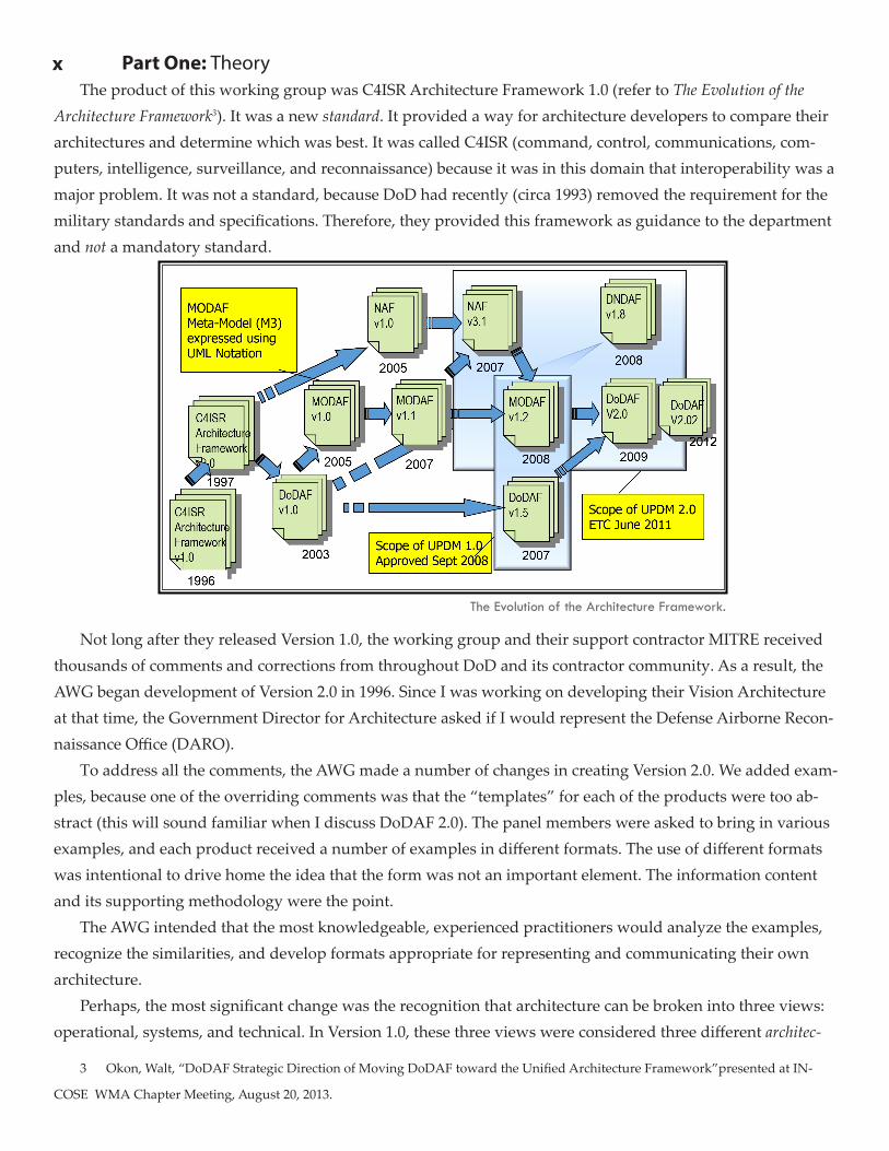
x Part One: TheoryThe product of this working group was C4ISR Architecture Framework 1.0 (refer to The Evolution of the
Architecture Framework3). It was a new standard. It provided a way for architecture developers to compare their architectures and determine which was best. It was called C4ISR (command, control, communications, com-puters, intelligence, surveillance, and reconnaissance) because it was in this domain that interoperability was a major problem. It was not a standard, because DoD had recently (circa 1993) removed the requirement for the military standards and specifications. Therefore, they provided this framework as guidance to the department and not a mandatory standard.
Not long after they released Version 1.0, the working group and their support contractor MITRE received thousands of comments and corrections from throughout DoD and its contractor community. As a result, the AWG began development of Version 2.0 in 1996. Since I was working on developing their Vision Architecture at that time, the Government Director for Architecture asked if I would represent the Defense Airborne Recon-naissance Office (DARO).
To address all the comments, the AWG made a number of changes in creating Version 2.0. We added exam-ples, because one of the overriding comments was that the “templates” for each of the products were too ab-stract (this will sound familiar when I discuss DoDAF 2.0). The panel members were asked to bring in various examples, and each product received a number of examples in different formats. The use of different formats was intentional to drive home the idea that the form was not an important element. The information content and its supporting methodology were the point.
The AWG intended that the most knowledgeable, experienced practitioners would analyze the examples, recognize the similarities, and develop formats appropriate for representing and communicating their own architecture.
Perhaps, the most significant change was the recognition that architecture can be broken into three views: operational, systems, and technical. In Version 1.0, these three views were considered three different architec-
3 Okon, Walt, “DoDAF Strategic Direction of Moving DoDAF toward the Unified Architecture Framework”presented at IN-
COSE WMA Chapter Meeting, August 20, 2013.
The Evolution of the Architecture Framework.
Preface: Do We Still Need a DoD Architecture Framework? xi
tures. That change in 2.0 was significant, because it was the realization that the three views are highly depen-dent, overlapping, and not completely separate architectures. Unfortunately, DoD has not fully understood or embraced this change. For example, many of the Services still have an Operational Architect, a Systems Ar-chitect, and a Technical Architect. Since we recognize that these views are interdependent, this means that the three different architects (and their organizations) must coordinate completely to ensure that the three views come together properly. As you can imagine, this makes it very difficult to obtain an integrated architecture, because any organization wants to have a level of autonomy from another.
We have seen this problem occur within major architecture programs as well. It seems natural to divide the work by the work products. The results of the different efforts must integrate with the overlaps removed. We know that this usually makes integration difficult, if not impossible, without tremendous effort. Many of the major architectures use hundreds of people to conduct them and take years to complete. As a counterpoint, the DARO Vision Architecture, which had the stunning breadth of all airborne reconnaissance platforms and ground systems as part of its charter, was accomplished in a matter of months by no more than a dozen peo-ple. Many of those people had other jobs in addition to the architecture work. For the ground based infrastruc-ture, which today forms the basis for the Defense Common Ground System (DCGS), Dr. David Craig, a bril-liant engineer from MITRE, and I were the two primary contributors to this part of the Vision Architecture. We captured the entire architecture (platforms and grounds systems) in a system-engineering tool (CORE) at six levels of decomposition in a matter of two months time. The rest of the study period was devoted to validating the architecture and briefing it at the Office of the Secretary of Defense (OSD) and the rest of the community.
The DARO Vision Architecture was the first time I employed this tool, process, and technique on an ar-chitecture project. We had used it for a number of years on Advanced Concept Technology Demonstration (ACTD) projects with great success. I will present this methodology in more detail in Chapters 7-13.
Not long after C4ISR Architecture Framework Version 2.0 was released, OSD/C3I and the Joint Staff, J-6 committed to make use of the Framework mandatory for the C4ISR domain. Until that time, it was guidance only. However, no directives, regulations, or instructions were changed; subsequently, the memo was no longer valid after six months. Some major users, such as the US Transportation Command (USTRANSCOM), embraced and expanded the application of the Framework beyond the C4ISR domain to other areas; others just ignored it.
Those of us on the panel knew this was similar to any product developed by a committee, an incomplete set of compromises, but a good starting point. We knew there were many things excluded, such as metrics, costing, levels of hierarchy, and use of simulation. We anticipated that these would be resolved in Version 3.0. However, some events got in the way.
First, we had the looming potential crisis of the Y2K4 problem. This was a result of decades of code written for computers with limited memory. Few people realized that the complex space systems that traveled to and landed on the Moon had orders of magnitude less memory than the modern pocket calculator. Many pro-grammers assumed that you needed only two digits to specify the date (e.g., 59 would represent 1959, because the first two would always be “19”). This was not a problem until the calculations approached the turn of the
4 Y2K or Year 2000 problem required a major amount of effort from Government and Industry. For more information see http://
www.y2ktimebomb.com/, accessed August 2010.
xii Part One: Theory
millennium. If you wanted to determine how many years had elapsed between 1989 and 1959 the calculation would result in 30 (89 - 59). However, if you wanted to find the same thing between 2005 and 1985, the result would be -80 (05 - 85) and not 20 years as one might expect. This could cause some very significant problems if the algorithms did not handle the problem correctly (and many, unfortunately, did not).
DoD arrived late to the Y2K party, as the insurance companies, elevator manufacturers, and others in the commercial sector had run into the problem as early as the late 1980s. DoD was concerned that major sensor and weapons systems, both strategic and tactical, could be affected, giving enemies an opportunity to strike. Fortunately, DoD made a crash effort, and no major failures were observed.
After the Y2K problem passed, a number of drafts emerged from the team developing the Framework. One of the most interesting came in 2000. This draft included the option that Object-Oriented methodologies were valid for developing C4ISR Architecture Framework products. Although you could use any notation or methodology, a number of people had begun interpreting the Framework to allow only diagrams similar to the examples shown in the document to remain compliant. Since these products were all structured analysis diagrams (IDEF, Yourdon-Demarco, etc.), people assumed that you could not use the recently emerging Ob-ject-Oriented techniques created for software development.
Another interesting feature of this draft was the extension of the Framework to all of DoD and the tentative versioning: DoDAF 2.1 (not to be confused with the current DoDAF 2.0). The changing version numbers has caused some confusion. Many people did not understand why the versioning started with the C4ISR AFs was not continued, but applying it to DoD was a whole new way to look at the problem.
After a number of other drafts (of Version 1.0) in 2003, the final Version 1.0 was released on February 9, 2004. The major changes from C4ISR AF v. 2.0 to DoDAF v. 1.0 were the following:
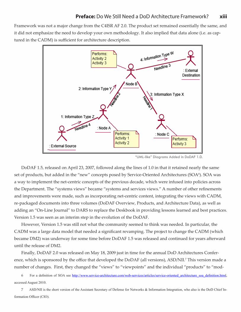
• Applied to all DoD.• Restructured: 2 Volumes and a Deskbook for implementation.• Based product selection on the intended use of the architecture. • Removed “Essential” and “Supporting Products.”• Moved toward a data-centric approach, less oriented toward products.• Replaced most examples with the Deskbook.• Emphasized “capabilities,” not requirements.• Another change was the inclusion of “UML-like” diagrams (refer to “UML-like” Diagrams Added in
DoDAF 1.0).5 The reason we say “UML-like” is although they use some of the UML notation, such as the very unpopular stick figures, these diagrams do not show up in the UML specifications.
In addition to the changes in the Framework itself, OSD revised every major policy to include architecture products. These policies included ones related to fielded systems, as well as ones in the acquisition process, thus making DoDAF products essential for funding all DoD programs. OSD also developed a data-centered archi-tecture repository, called the DoD Architecture Repository System (DARS). It used the Core Architecture Data Model (CADM) as the basis for export and import into DARS.
The bottom line on DoDAF 1.0 is that it enhanced readability by expanding the volumes; improving the text; and providing insights into ways to employ the Framework (in the DoDAF 1.0 Deskbook). Otherwise, the
5 DoD Architecture Framework v. 1.0, 9 February 2004, Volume II, p. 4-11.
Preface: Do We Still Need a DoD Architecture Framework? xiii
Framework was not a major change from the C4ISR AF 2.0. The product set remained essentially the same, and it did not emphasize the need to develop your own methodology. It also implied that data alone (i.e. as cap-tured in the CADM) is sufficient for architecture description.
DoDAF 1.5, released on April 23, 2007, followed along the lines of 1.0 in that it retained nearly the same set of products, but added in the “new” concepts posed by Service-Oriented Architectures (SOA6). SOA was a way to implement the net-centric concepts of the previous decade, which were infused into policies across the Department. The “systems views” became “systems and services views.” A number of other refinements and improvements were made, such as incorporating net-centric content, integrating the views with CADM, re-packaged documents into three volumes (DoDAF Overview, Products, and Architecture Data), as well as adding an “On-Line Journal” to DARS to replace the Deskbook in providing lessons learned and best practices. Version 1.5 was seen as an interim step in the evolution of the DoDAF.
However, Version 1.5 was still not what the community seemed to think was needed. In particular, the CADM was a large data model that needed a significant revamping. The project to change the CADM (which became DM2) was underway for some time before DoDAF 1.5 was released and continued for years afterward until the release of DM2.
Finally, DoDAF 2.0 was released on May 18, 2009 just in time for the annual DoD Architectures Confer-ence, which is sponsored by the office that developed the DoDAF (all versions), ASD/NII.7 This version made a number of changes. First, they changed the “views” to “viewpoints” and the individual “products” to “mod-
6 For a definition of SOA see http://www.service-architecture.com/web-services/articles/service-oriented_architecture_soa_definition.html,
accessed August 2010.
7 ASD/NII is the short version of the Assistant Secretary of Defense for Networks & Information Integration, who also is the DoD Chief In-
formation Officer (CIO).
“UML-like” Diagrams Added in DoDAF 1.0.
xiv Part One: Theory
els.” It also added several new “viewpoints” (Capability, Data and Information, and Project), while separating systems and services into their own “viewpoints.” DoDAF 2.0 now claimed to provide a “methodology,8” a set of methods, processes and rules, for developing architectures. However, as Chapter 3 demonstrates, their methodology is incomplete and does not constitute what you really need, which is a combination of people, detailed processes to the procedural level, and tools founded on good systems engineering principles. That’s alright, because they cannot and should not dictate that level of approach as it would lead to poor perfor-mance due to lack of competition.
DoDAF 2.0 did something else, which many in the DoDAF community feel is unusual. They removed all the diagram templates from the descriptions of the models (previously called products). Above, I mentioned that C4ISR Architecture Framework 1.0 suffered from this lack of visualization. The DoDAF 2.0 came to this conclusion because of a desire to push a “data-centric” view of architecture and the confusion many had about the templates being a required form. That is why we have come full circle on visualization. Since architecture is defined as both “style and method of design and construction,9” the style part or some call it “art” of archi-tecture is missing from the Framework. As an architect, I’m fine with that because it allows me the freedom to put the art I think looks best into the end product. However, for use as a comparison tool, the decision maker will now be bombarded with many different “looks” to choose from, thus making the job of comparing dif-ferent architectures more difficult, not less, as was the original goal of this Framework. Many other features of DoDAF 2.0 will be discussed throughout this book, including the new DoDAF Meta-model (DM2).
8 “A body of methods, rules, and postulates employed by a discipline,” from Merriam-Webster Online, http://www.merri-
am-webster.com/dictionary/methodology, accessed August 2010.
9 Definition from The Free Dictionary by Farlex, http://www.thefreedictionary.com/architecture, accessed August 2010.
Part One: Theory
Chapter 1
In This Chapter
► The Definition of an Architecture and its Purpose ► A Clear Understanding of the DoD Architecture Framework ► Uses of Architecture by Government and Industry ► DoDAF Key Concepts and Definitions
Types of ArchitecturesAs discussed in the Preface, there are all kinds of architectures:• House/Building Architecture• Information Architecture• Enterprise Architecture• Technical Architecture• Logical Architecture• Physical Architecture• …From all these different “architectures,” and differing contexts, we might conclude it is one of the most
abused words in systems engineering and enterprise architecture practice today. In addition, we will continue to abuse it throughout this book. However, before we add to the list, let’s explore what each of the architec-tures above is about, their characteristics, and where they apply.
The first one, house or building architecture, is clearly the most recognizable by a general audience. This type of architecture refers to the structure of the building and includes the location of all the electrical outlets, plumbing, and other “interfaces” with the outside world. It adheres to the basic principles of form, fit, and function. The form is important, as it will provide the style of architecture (modern, classic, etc.) that appeals to the tastes of the owners and architects. The fit ensures that the plans meet all the constraints (size of the lot, building codes, etc.) The function of the building is incorporated in the blueprints, as each room will be desig-nated for certain activities (the kitchen for cooking, the office for work, etc.). When you speak of “architec
What is the DoDAF Anyway?
2 Part One: Theoryture” or being an “architect,” most people, including many of those in DoD, will assume this is the kind of
architecture that you are discussing.The second one, information architecture, refers to the data and resulting information that flows through
your organization or system. Information is usually captured in a series of data descriptions, in the form of class diagrams (if you are using object-oriented methods), or entity-relationship-attribute (ERA) diagrams (if you are using structured analysis methods).
The third one, enterprise architecture, refers to the overall architecture of your organization. This “archi-tecture’ will include your information, business processes, and systems. For another definition for enterprise architectures from the Office of Management and Budget (OMB) refer to the box.
The fourth one, technical architecture, is an odd term. It refers to the standards that apply to your architec-ture. What makes this odd is that many people assume this term only applies to technical standards, such as IPv6 for the Internet. It can (and should) also include operational standards, such as Joint Tactics, Techniques, and Procedures (JTTP) or the Capability Maturity Model-Integrated (CMMI). An example of this type of archi-tecture created in the early days of the C4ISR Architecture Framework was called the Joint Technical Architec-ture (JTA). The DoD Information Technology (IT) Standards Registry (DISR) On-Line has replaced this docu-ment. You can access this registry on the Defense Information Systems Agency (DISA) websites on SIPRnet and NIPRnet (networks for classified and restricted information).
The fifth and sixth items on the list, logical and physical architectures, are more traditional ways systems engineers have broken out architectures. The logical architecture was represented by the functional flows and data elements, and the physical architecture was represented by the components of the system and the interfaces between them. To link together the two architectures, you simply allocate functions to components (and data elements to interfaces). This is the reason for the terms functional analysis and allocation from classical systems engineering processes and texts.
As you can see, there are many ways to interpret the term “architecture.” However, you may be asking yourself, “Why should I care?”
Uses of Architectures by Government and IndustryThe answer to that question really begins with the recognition that commercial, as well as Government,
In Case You Didn’t Know...The JTA was preceded by the Army Technical Architecture (ATA), from which the JTA was derived; the Army has
been a leader in architectures for a long time.
Definition 1.1“An EA (Enterprise Architecture) is the explicit description and documentation of the current
and desired relationships among business and management processes and information
technology.”
- Office of Management and Budget
Chapter 1: What is the DoDAF Anyway? 3organizations use architecture to understand what technology is needed and when to invest in that technology. Of course, the driving technology is information technology (IT). IT has changed over the past three decades at a breath taking pace. It becomes very hard to predict when the best time is to invest in updating comput-ers, software, servers, networks, and other IT tools. New concepts like Service-Oriented Architectures (SOA), Cloud Computing, iPads, Android Apps, etc.10 appear at a startling pace every day. The impact on business processes and training can be prohibitive, in terms of both cost and time. The need to control the investment. Architectures provide insight into the business processes and systems and how they interact with one anoth-er and how to best use the technology. By providing traceability between requirements (including those for training, functions, and components) we can determine the impact of changes and determine the best timing for replacements.
In addition to guiding technology investments, the analysis of business processes can often enable you to conduct your business and increase productivity. People have called this analysis a number of things: function-al analysis, integrated process design and development, business process re-engineering, etc. You can use your architecture to improve the way you do business (which includes warfighting) with or without changing the underlying technology.
Another use for architectures is to provide a logical means to reorganize your operations. How do compa-nies re-organize today? In reality, most do it around people. A company hires someone with a desired skill set, and then reorganizes the company, division, or office around that skill set. Instead, if there is a more objective analysis of the business processes, then you can allocate processes to organizational components; give your organization more coherence; and minimize problems between interfacing organizations. You can even trace these functions back to strategic objectives (requirements) and know why a certain organization or even a par-ticular job is necessary for the health of the company.
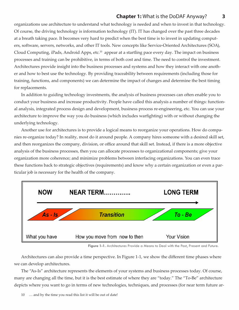
Architectures can also provide a time perspective. In Figure 1-1, we show the different time phases where we can develop architectures.
The “As-Is” architecture represents the elements of your systems and business processes today. Of course, many are changing all the time, but it is the best estimate of where they are “today.” The “To-Be” architecture depicts where you want to go in terms of new technologies, techniques, and processes (for near term future ar-
10 … and by the time you read this list it will be out of date!
Figure 1-1. Architectures Provide a Means to Deal with the Past, Present and Future.
4 Part One: Theorychitecture, such as those related to information technology) or for longer term efforts the capabilities you want to achieve in the future, since often you do not know or want to specify the specific technologies of the future. This “To-Be” architecture can become the foundation for your long-term strategic plan. The “Transition” architecture provides the means to get from the “As-Is” to the “To-Be.” You might define a number of “Transi-tion” architectures, perhaps providing new plans for every five years or even annually (to fit the United States budget cycle). By the way, the FEA Practice Guidance11 contains a similar picture and discussion for enterprise architecture transition strategies.
You might ask the questions: “Which is the easiest to do?” and “Which is the hardest to do?” Perhaps the easiest is the “To-Be,” since that architecture is the least constrained by technological and political realities of today. However, without knowledge of the future, the “To-Be” is very difficult. Some would say that the “As-Is” is the easiest, since it exists. However, the “As-Is’ is a bit more difficult than most people realize, because it is a moving target. If the documentation exists, it is usually out of date. The bureaucracies that form around viable business processes often keep the real processes hidden.
The hardest may really be the transitional architectures. These have all the difficulties mentioned above for the “As-Is,” but they also have a major problem they must overcome: politics. Why politics? Because the transitional architectures affect how future money will be spent, and hence the budget. Budget development is perhaps the most political thing we do in the Government arena. Billions are spent on lobbyists, advertising, proposals (both solicited and unsolicited), independent research, development (IR&D), and overhead to obtain future business. This competition is good for the Government since it tends to reduce long-term costs and pro-vide more capability, but it adds to the complexity of producing architectures. As to which ones should you do and in what order, we recommend that you begin with the “As-Is”, or at least, portions of it to understand the existing and planned systems/processes. You need to look at these first to identify shortfalls or other related issues, as well as to avoid the “reinvention of the wheel” syndrome, where you end up creating “new” capa-bilities that only marginally (if at all) improve the situation. By having a firm understanding of what you are doing today, you can then make the “To-Be” (the next step) into a significant improvement, rather than just an incremental one. You need a first cut at the “As-Is” and “To-Be” to develop rational transition architectures. For example, I watched one architecture effort try to do all three in parallel—with different teams. The transition plan was evaluated as “a plan to write a transition plan.” Clearly, that approach does not work well and is frus-trating for everyone involved.
Please note that architectures can (and should) be a means of deriving the necessary requirements, including system design, test & evaluation (T&E), and operations & support (O&S). Many people see architectures as the production of a number of diagrams that have no real long-term use. They treat architecting as an exercise that’s been required by management (or in the case of U.S. Federal enterprise architectures – law). If instead we recognize that the correct application of architecture gives us the basic requirements needed to pursue sys-tem development and acquisition, we can immediately see the benefits of a well conducted architecture study.
11 FEA Practice Guidance, November 2007, p. 4-1, available at http://www.whitehouse.gov/sites/default/files/omb/assets/fea_
docs/FEA_Practice_Guidance_Nov_2007.pdf, accessed July 5, 2011.
Chapter 1: What is the DoDAF Anyway? 5
1.1 What is Architecture?We have discussed different types of architectures, and how they might be useful, but we really have not
defined what makes up architectures in detail. So let’s look at some definitions for architecture, starting with the one from the DoDAF itself.12
Whereas this definition gives a good short definition, it does not really tell us what information we need to describe the architecture. However, DoDAF goes well beyond this simple definition. DoDAF 1.0 and 1.5 broke architecture into three views: operational, systems, and technical standards. Figure 1-2 provides a depiction13 of the three views.
This drawing has some interesting connotations. First, notice that the different views are represented by different, unconnected planes. This might infer that they are independent of one another. This thought comes from the idea that you can treat these as separate “archi-tectures” by themselves, which goes back to C4ISR Architecture Framework, Version 1.0, as discussed in the Preface. Another “miss-ing item” is the lack of any attempt to depict the business processes – no flow diagrams or process/procedure books. It seems to be about the hardware and software. Another “problem” with this diagram is the possi-ble implication that technical standards are static. However, those of us involved in the world of IT standards know how rapidly they are changing. New web standards are coming out all the time. With the advent of SOAs and Cloud Computing, we can envi-
12 Note that version 2.0 does not contain this statement. It comes from Version 1.0 and 1.5. This statement was used in a draft
document entitled Essential DoDAF, which has not been finalized to date.
13 From the “Integrated DoD Architectures” brochure, available at http://www.dod.mil/c3i/org/cio/i3/ AWG_Digital_Library/pdf-
docs/brochure.pdf, no longer available at this site (last accessed January 2008).
Definition 1.2Architecture: “A set of abstractions and models that simplify and communicate complex struc-
tures, processes, rules, and constraints to improve understanding, implementation, forecast-
ing, and resourcing.”
- DoDAF
Figure 1-2. Architectures Provide a Means to Deal with the Past, Present and Future.
6 Part One: Theory
sion even more changes in the near future.
DoDAF 2.0 compounds these difficulties by adding new sets of “views” or viewpoints14 (refer to Figure 1-315). This adds a capability layer above the operational, with the intent of improving the adherence to the top-down capability-based approach now in DoD policies, such as CJCSI 3170.01G and greater. This version also splits out the services from systems as a layer in-between operational and systems, reflecting the focus on services or SOAs as a means to implement net-centricity, which we will define in more detail later. It also recognizes that the standards actually cross the range of top-down viewpoints (capability through systems), as does the All, Data and Information, and Project viewpoints.
These additional “viewpoints” add complexity, but align with the policies and approaches currently being promulgated by DoD. They also better enable DoDAF’s use in developing enterprise architectures and SOAs.
The terms models, views, and viewpoints have become a key part of the DoDAF definition for architecture
14 An “organized collection of views (often representing processes, systems, services, standards, etc.) are referred to as view-
points, …” The Essential DoDAF, IBID, p.4.
15 DoD Architecture Framework Version 2.0, Volume 1, p. 21.
Figure 1-3. Architectures Provide a Means to Deal with the Past, Present and Future.
In Case You Didn’t Know...Note that DoDAF is but one of many widely-accepted architecture frameworks. Zachman, IEEE 1471, RM-ODP,
the FEAF and others provide alternative frameworks in this area.
Chapter 1: What is the DoDAF Anyway? 7
and architecture description.16 Figure 1-4 shows this relationship. The models (previously called products) are abstract descriptions of the information needed to represent a portion of the overall architecture. When the models are combined with the appropriate data, they form the views. A viewpoint, then becomes a collection of views. Although these distinctions are made in other standards (e.g., IEEE 1471), they add confusion to the average DoD contractor or employee who builds or has to understand these products. Try to not let your client get wrapped around this axle. Now, let’s look at some other definitions for architectures. In her book entitled, Building Enterprise Information Architectures, Melissa Cook states: “An architecture provides the basis for busi-ness control over the contractors.17” This book helps architects who want to create Enterprise Architectures or Information Architectures.
In their book, The Art of Systems Architecting, Maier and Rechtin define architecture as “The structure – in terms of components, connections, and constraints – of a product, process, or element.18” This definition be-gins to define the parameters that are needed to describe an architecture (components, connections and con-
16 DoDAF now defines the architecture description as a collection of products to document an architecture (see IEEE 1471).
17 Building Enterprise Information Architectures, Melissa A. Cook, 1996, p. 13, Prentice Hall PTR.
18 The Art of Systems Architecting, Third Edition, Mark W. Maier and Eberhardt Rechtin, 2009,
p. 415, CRC Press, Inc.
Figure 1-4. Relationship between Models, Views and Viewpoints.
In Case You Didn’t Know...DoD policies such as CJCSI 3170.01G change all the time, so check http://www.dtic.mil/cjcs_directives for the latest
version.
8 Part One: Theory
straints). It also provides a number of “rules of thumb” for developing good architectures; architecture is not just an engineering discipline – it is also an art form.
A third book provides another perspective on decomposition by views. Dennis Buede’s seminal system en-gineering text includes the following: “Levis [1993] has defined an analytical systems engineering process that … includes three separate architectures (functional, physical, and allocated19) … ” Many system-engineering schools currently use Buede’s book as a basic textbook.
By looking at all of these definitions and thinking more about the parameters used to describe architec-tures, we have developed a useful definition (see Definition 1.3).
This definition implies that we need a number of fundamental parameters (or dimensions) to describe the architecture, including risks, issues/decisions, inputs, outputs, assets (systems, components, organizations), actions (tasks, functions, activities), statements (requirements, constraints), characteristics (performance, attri-butes), etc. Although this is potentially a substantial list (around 12 parameters or so), it is finite, and you can gather it in a reasonable amount of time. Notice that we have included parameters that you might consider “programmatic,” such as risks and issues/decisions. In addition, we have included those parameters, because we see architecture development in a similar light as systems engineering; they both have technical and man-agement aspects, since they both influence (or should) the decision making process for acquisition.
The unifying structure refers to relationships between the elements. For example, Actions are performed by Assets. These relationships also establish the context for elements within a class (e.g., an Asset may be decom-posed by a number of other Assets). In this way, we can show the context for an elements without having to create long names. In the data-centric world the fuel tank for an M1A1 tank might look like this: M1A1_Fuel-System_fuelTank. Instead we can establish all the relationships that a fuel tank decomposes the fuel system that is a part (decomposes) the M1A1 tank.
You may also note that we have explicitly included “behaviors” in our definition. Why is behavior im-portant (and what is it)? Behavior refers to the way an architecture works, usually expressed in terms of the functions performed, resources used, and overall systems performance. As architects, we want to control the behavior of the systems captured in the architecture as much as possible and not have “emergent” or unpre-dictable behavior.
Now that we have a working definition for architectures, we need to explore the adjective “executable” as applied to architecture. Executable architecture refers to the use of dynamic simulation software to evaluate architecture models.
What do executable or dynamic architectures do for us? • verify the logic of operational activities and systems functions, thus enabling the evaluation of dynamic
performance that would not easily be predicted by analyzing static diagrams
19 The Engineering Design of Systems, Dennis M. Buede, 2000, p. 19, John Wiley & Sons, Inc.
Definition 1.3Architecture: A fundamental and unifying structure defined in terms of elements, information, interfaces, processes, constraints, and behaviors.
Chapter 1: What is the DoDAF Anyway? 9
• estimate timing concerns (e.g., bottlenecks)• estimate impact on resources• draw connections between people, hardware and software• analyze architecture measures for decision support, including cost-benefit tradeoffsUsing them helps us answer basic questions: Is the architecture logically correct? Does the architecture
exhibit the desired behavior? Does the information arrive at the right functions in the right sequence, i.e., are the inputs processed in the required way? Is the system perspective of the architecture consistent with the operational? Do instantiations of this architecture exhibit the desired performance characteristics? Do systems built in conformance to the architecture provide the desired capability?
It also helps us analyze alternatives, such as: How are MOPs and MOEs affected by different arrange-ments and by different physical allocations?
The point is we need to be sure our architectures work before going to the system design level. By developing an executable architecture, we can verify that the logic is correct and that it has predictable performance. Very few of the architecture developments to date within the DoD (and the rest of the Gov-ernment and industry for that matter) are truly executable. Often, we do not discover the problems until much further downstream in the development process and thus end up incurring much greater costs to fix the problems we do find.
1.2 What is DoD Architecture Framework?
The next question in your mind must be “so what’s this framework? ” “Is it an architecture or what?” To answer this, we need to recognize that the DoDAF was developed as a means to compare architectures. It is not an architecture or a methodology to develop architectures. Instead, it enables this comparison by defining a set of views of an architecture.
These models (according to DoDAF 1.5 and its predecessors) were originally grouped into only the four views:
• Operational View• Technical Standards View• Systems View• All-View The all-view models were meant to span and link the other three views, but these are just views of
your architecture. As we discussed in the Preface, the three categories of views (operational, systems and technical) are just a way to divide the architecture. This way, different constituents can have the views that they find most useful and interesting. In fact, you may think about the way that we currently divide DoD into Commands, Services and Agencies (CSA). Commands perform the warfighting or “operational” tasks. Services (Army, Navy, and Air Force) provide the equipment and training (i.e. systems) to conduct operations. Agencies (of the Office of the Secretary of Defense) provide standards (primarily through poli-
10 Part One: Theorycies) for conducting the warfighting and contribute to the acquisition process.
Is this a bad thing? No. We should always want to portray the architecture in ways that best communicate the results to different groups of users, including decision makers. The fact that we have the CSA structure in DoD is a good thing. In addition, it is intelligent to formulate a means of architecture comparison that follows along those lines. However, as you can imagine it can be a disaster in trying to develop architectures, because the three views overlap. People often miss this point, when they try to integrate the models. A number of methodologies have made this attempt. As practitioners and observers of architecture development, we have found that trying to use the Framework as a basis for methodology leads to poor, non-executable architectures. In Chapter 4, we will discuss executable methodologies for developing architectures.
As we have seen with DoDAF 2.0 new views (viewpoints) have been added (Capability, Data and Information, Services, Project) to address concerns of groups within the CSA construct. The Capability mod-els address the “needs” of high-level decision makers (policy makers) and enterprise architects with a goal of integrating the architecture description so that it supports those needs and communicates what policy makers want with the other stakeholders. The Data and Information models include diagrams that were previously in the operational and systems views (OV-7 and SV-11) and with the conceptual data model enable the more complete capture of the information architecture. CIOs, their staffs, and support contractors now have a view-point of their own. Services models provide a way to separate SOA developers from the systems; although they could easily do so without creating a duplicate set of models with slightly different names (we did this for several SOA/net-centric architectures using the DoDAF 1.5 terminology without any difficulty). Finally the Project models support the acquisition process, although they seem to be missing the most important ingredient to acquisition – cost. Of course costing is often handled by a different group than the architects, but in acquisition the two groups must come together. In systems engineering we always discuss three critical parameters: cost, schedule, and performance. The goal of systems engineering is to balance these three param-eters to develop an optimum system. The same principle should apply to architectures as well. However, if we continue to ignore cost, we will continue to specify services and systems that have huge cost overruns and constantly risk cancellation.
Let’s begin by trying to understand more about DoDAF itself. In DoDAF 1.5 and its predecessors, mod-els were allowed to be represented in many different forms: graphics, text, and tables (Figure 1-5. It specified the information content for models in each view, but not the specific form (see Tip 1.1). Many people looked at the “templates” associated with the DoDAF 1.5 and assumed that was the only allowable form; but clearly you had the flexibility and freedom to present the information in a useful way to the users or evaluators of the architecture.
In DoDAF 2.0 they codified this principle by using the term “fit for purpose.” Since this Framework can be
Tip 1.1“The Framework does not advocate the use of any one methodology (e.g., structured analysis vs.
object orientation), or one notation over another (IDEF1X or ER notation) to complete this step, but
models should contain the required information and relationships.”
-DoD Architecture Framework, Version 1.0 (February 9, 2004) Vol. II, p. 2-8
Chapter 1: What is the DoDAF Anyway? 11used at many levels of an enterprise, each level will require different content, structure, and level of detail. Tai-loring the models to address specific needs enables the architect to collect information about the architecture at the appropriate level of detail to support specific decisions or objectives. Hence, the specific models and form of those models depends on the intended use of the architecture, as discussed later in this chapter.
If they improve communication of the architecture, then additional models are allowed. In fact, most people will tell you that the set of models is insufficient to provide the views needed. As you can see, this need for additional “models” or views implies the need for a more complete approach to architecture development. Development of additional worthwhile models requires a well-founded, well-applied methodology based on the rigorous application of systems engineering principles. In fact, the original intent of the DoDAF was to encour-age the use of systems engineering methodologies to develop architectures.
Next, we need to look at some of the key concepts and definition associated with the DoDAF. We will also identify and discuss several myths that surround the Architecture Framework.
1.3 What are the Key DoDAF Concepts and Definitions?
Let’s start with a brief discussion of the Framework’s philosophy. As we have previously stated, the DoDAF provides guidance for describing architectures. It is not a “How To” build architectures document. Although DoDAF 2.0 makes this claim now, all it provides is a high level process with the same six-steps that
Figure 1-5. Presented by Mr. Truman Parmele at the DoD Architectures Conference February 24, 2004.
12 Part One: Theorywere used in DoDAF 1.0 and 1.5. Version 2.0 provides more detail on each of these steps in Volume 1, which includes discussion of using “fit-for-purpose” views to ensure that your architecture meets the stakeholders’ needs. Hence, the ball is still in your court. You have to define these “fit-for-purpose” views, the data, analysis techniques, tools and the detailed processes and procedures.
DoDAF provides some, but not all, of the parameters that enable comparison. For example, one of the models deals with performance, but no metrics were specified. None of the models explicitly deals with cost (an important parameter for decision makers).
The DoDAF provides guidance to the entire Department. No longer can organizations outside the C4ISR domain ignore this guidance. DoDAF models are required in virtually all major DoD acquisition policies. The budget for your program now depends on having DoDAF models available for evaluation by the Joint Staff and OSD.
Perhaps one of the most important philosophical comments about the DoDAF comes from Definition 1.4. This quote recognizes that the United States does not fight wars alone. In every major conflict, throughout the history of our nation, we have had allies. For example, imagine where this nation would have been without the French Navy during the Revolutionary War.
The fact that DoD has now defined these architecture models also means that those organizations within and without the U.S. have a great interest in the DoDAF. The United Kingdom has the “MODAF” (Ministry of Defense Architecture Framework). Australia has the “DAF” (Defense Architecture Framework). These other frameworks are modeled after the DoDAF, and they extended the DoDAF views. For example, the DAF de-fines Common (CV) and Data (DV) Views in addition to the operational, systems and technical.
Definition 1.4DoD Architecture Framework: “… defines a common approach for Department of Defense (DoD)
architecture description development, presentation, and integration. The Framework is intended to
ensure that architecture descriptions can be compared and related across organizational boundar-
ies, including Joint and multinational boundaries.”
-DoD Architecture Framework, Version 1.0 (09 February 2004)
Myth #1The Framework provides a definitive means for comparing architectures
• In reality, the Framework (and in particular the essential models) does not provide all the information needed
by decision makers.
• No common metrics are provided for comparing performance or cost.
• The architectures could actually reference different levels of decomposition, no hierarchy was defined.
• The Framework was seen to provide a means to force architects to use good systems engineering techniques
to develop the views, thus making it possible to provide additional information needed by decision makers.
• These limitations were noted at the time and were determined to be unworkable at that time. The assumption
at the time was that C4ISR AF version 3.0 would try to resolve these deficiencies.
Chapter 1: What is the DoDAF Anyway? 13
All this philosophical discussion leads us to our first “myth.”As those who know the differences between the C4ISR Architecture Framework 2.0 and DoDAF 2.0 can
readily attest that Version 3.0 has not arrived yet and probably never will. The improvements in the DoDAF itself still do not address these fundamental issues. Version 2.0 gets us somewhat closer in that it clearly states you should create architecture descriptions to support a purpose, thus giving the decision-makers the informa-tion they need to make an informed decision. You have to add this “fit-for-purpose,” it’s not in the DoDAF itself. In particular, the metrics can be quite difficult to develop and they likely will be different for different architec-tures and teams.
Now that we understand some of the underlying philosophy, let’s look at some of the concepts, some of which may be new to you (as they were to me) that were put forth by the Framework.
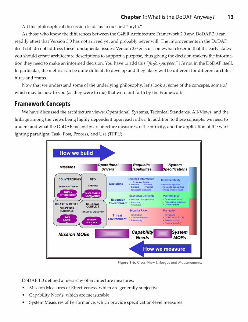
Framework ConceptsWe have discussed the architecture views: Operational, Systems, Technical Standards, All-Views, and the
linkage among the views being highly dependent upon each other. In addition to these concepts, we need to understand what the DoDAF means by architecture measures, net-centricity, and the application of the warf-ighting paradigm: Task, Post, Process, and Use (TPPU).
DoDAF 1.0 defined a hierarchy of architecture measures:• Mission Measures of Effectiveness, which are generally subjective• Capability Needs, which are measurable• System Measures of Performance, which provide specification-level measures
Figure 1-6. Cross-View Linkages and Measurements.
14 Part One: TheoryFigure 1-6 from DoDAF 1.0 shows how these measures relate to the overall architecture development pro-
cess.20 This seems odd that people consider a mission’s measure of effectiveness subjective, yet people consider a capability need measurable. However, we need to understand their definitions and use them if we are going to communicate effectively.
However, when this hierarchy was developed, the authors must have been unaware of a similar decompo-sition used by the test and evaluation community (T&E). They define the hierarchy of measurements as critical operational issues (COI), measures of effectiveness (MOE), and measures of performance (MOP). The defi-nition of these terms is similar to the ones used for Mission MOEs, Capability Needs, and System MOPs. We mention this distinction only to help avoid confusion. When architects talk to people in the T&E community, they should know this distinction.
In DoDAF 2.0, no reference to this diagram remains. In a search of the Volumes and the User’s Guide, the terms MOE and MOP only arise in Volume 2 as part of the description for the SvcV-7 (Services Measures Ma-trix) and the SV-7 (Systems Measures Matrix). Oddly, in these descriptions the definition of MOP as Measure of Performers, not Performance as has been the classical definition. Beware of people redefining common terms long in use. It can lead to great confusion.
Net-Centricity has been all the rage in DoD since the mid-1990s. Net-centricity is “the realization of a networked environment, including infrastructure, systems, processes, and people, thus enabling a completely different approach to warfighting and business operations. 21” To many people in DoD this means the use of internet-like networks with Internet Protocols, such as NIPRnet, SIPRnet, and JWICS, to make information and applications available to whoever needs it and whenever they need it. A better way to think about this is net-centricity should be about putting people first and then =doing the mission in a networked way. Major new architectures are using net-centric concepts, including Future Combat Systems (FCS) (now Brigade Com-bat Team Modernization22) for the Army and Net Centric Enterprise Services (NCES) at Defense Information Systems Agency (DISA). Net centricity requires reliable, and fast access to the network to accomplish these tasks. When the Navy proposed net-centric operations and warfare (NCOW) in the mid-1990s, the internet boom was in full force. Since there was a large the number of satellite and terrestrial networks in development, we anticipated that we would have access to 10 Megabits per second at low latencies anywhere on the planet. Unfortunately, most of those network developments collapsed with the “dot com” bust of 2000.
The lack of ubiquitous communications meant that our architectures had to deal with high bandwidth and low bandwidth users, thus making full net-centricity problematic for the warfighter. The concept of enclaves (capabilities tailored for the low bandwidth user) has recently gained interest and acceptance in the DoD com-munity.
For other views of net-centricity and related concepts, I recommend reviewing materials and information on the Command and Control Research Program (CCRP) website (www.dodccrp.org).
20 DoD Architecture Framework v. 1.0, 9 February 2004, Volume I, p. 4-5.
21 Department of Defense Net-Centric Data Strategy, May 9, 2003, p. 1.
22 Note that FCS and BCTM have been “killed.” However, many of the underlying systems still have value and build on the
net-centric concepts developed during this program. Since there is a need for an improved Army capability, we will see many of these
concepts return in the future. Old programs never die, they only get renamed.
Chapter 1: What is the DoDAF Anyway? 15Another concept we want to discuss is TPPU: Task, Post, Process, and Use. TPPU was to replace TPED
(Task, Process, Exploit, and Disseminate), which has been used in the Agencies, Services, and Intelligence Communities for decades. However, TPPU does not seem to currently be in vogue. I want to discuss the differ-ence still as it better applies to the Service Oriented Architecture (SOA) and Net-Centric concepts that are being implemented in the DoD today. TPED implies that the information gathered by various (classified) sensor systems would not be available until dissemination. This process implies significant amounts of time were nec-essary, because the “raw” sensor data had to be processed on the ground. Even then, it was difficult for anyone except an intelligence analyst to decipher and put into context.
With modern sensor systems that can operate at lower levels of classification, such as the streaming video from the Predator, warfighters can obtain immediate access to time critical information. Figure 1-7 represents a typical TPPU scenario.Step 1 (Task) represents the process of tasking an information gathering asset (in this case, a Predator that then
discovers an enemy missile launcher). Step 2 (Post) means the unanalyzed, collected information is made available to any authorized user. Step 3 (Process) means that multiple users can process the information to enable them to make a variety of
strategic (e.g. Pentagon), operational, or tactical (task a strike aircraft) decisions. Step 4 (Use) shows how the information can be used, in this case a strike aircraft receives ad hoc tasking to
destroy the missile launcher.Note that TPED is still heavily used in the intelligence and DoD communities. You may want to think
about applying TPPU instead on your next project as it fits better with the data sharing initiatives of the U.S. Government and DoD.
Now that we understand some of the underlying concepts, let’s look at some of the key definitions.
Figure 1-7. TPPU – Task, Post, Process, and Use.
16 Part One: Theory
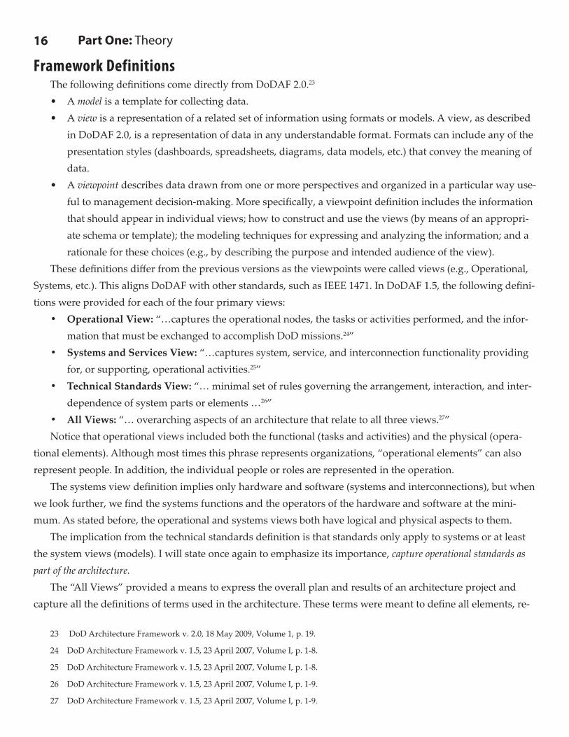
Framework DefinitionsThe following definitions come directly from DoDAF 2.0.23
• A model is a template for collecting data.• A view is a representation of a related set of information using formats or models. A view, as described
in DoDAF 2.0, is a representation of data in any understandable format. Formats can include any of the presentation styles (dashboards, spreadsheets, diagrams, data models, etc.) that convey the meaning of data.
• A viewpoint describes data drawn from one or more perspectives and organized in a particular way use-ful to management decision-making. More specifically, a viewpoint definition includes the information that should appear in individual views; how to construct and use the views (by means of an appropri-ate schema or template); the modeling techniques for expressing and analyzing the information; and a rationale for these choices (e.g., by describing the purpose and intended audience of the view).
These definitions differ from the previous versions as the viewpoints were called views (e.g., Operational, Systems, etc.). This aligns DoDAF with other standards, such as IEEE 1471. In DoDAF 1.5, the following defini-tions were provided for each of the four primary views:
• Operational View: “…captures the operational nodes, the tasks or activities performed, and the infor-mation that must be exchanged to accomplish DoD missions.24”
• Systems and Services View: “…captures system, service, and interconnection functionality providing for, or supporting, operational activities.25”
• Technical Standards View: “… minimal set of rules governing the arrangement, interaction, and inter-dependence of system parts or elements …26”
• All Views: “… overarching aspects of an architecture that relate to all three views.27”Notice that operational views included both the functional (tasks and activities) and the physical (opera-
tional elements). Although most times this phrase represents organizations, “operational elements” can also represent people. In addition, the individual people or roles are represented in the operation.
The systems view definition implies only hardware and software (systems and interconnections), but when we look further, we find the systems functions and the operators of the hardware and software at the mini-mum. As stated before, the operational and systems views both have logical and physical aspects to them.
The implication from the technical standards definition is that standards only apply to systems or at least the system views (models). I will state once again to emphasize its importance, capture operational standards as part of the architecture.
The “All Views” provided a means to express the overall plan and results of an architecture project and capture all the definitions of terms used in the architecture. These terms were meant to define all elements, re-
23 DoD Architecture Framework v. 2.0, 18 May 2009, Volume 1, p. 19.
24 DoD Architecture Framework v. 1.5, 23 April 2007, Volume I, p. 1-8.
25 DoD Architecture Framework v. 1.5, 23 April 2007, Volume I, p. 1-8.
26 DoD Architecture Framework v. 1.5, 23 April 2007, Volume I, p. 1-9.
27 DoD Architecture Framework v. 1.5, 23 April 2007, Volume I, p. 1-9.
Chapter 1: What is the DoDAF Anyway? 17
lationships and attributes of the architecture (i.e. the data that describes the architecture in data-centric terms). Too often practitioners thought this was a simple glossary or acronym lists.
The focus on systems-related standards may be due to the interest in interoperability and the miscon-ception that interoperability is mostly a systems problem. As most communications experts will tell you, for complete communications to occur, it requires standards at all levels, including the language and context. Lan-guage depends on the standardization of terms and context and often includes assumptions on the processes. Therefore, technical standards must also include operational standards. DoDAF 2.0 has corrected this miscon-ception (see below).
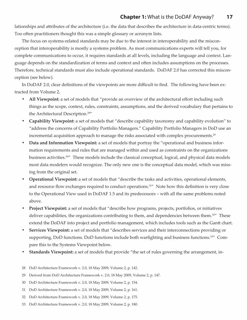
In DoDAF 2.0, clear definitions of the viewpoints are more difficult to find. The following have been ex-tracted from Volume 2.
• All Viewpoint: a set of models that “provide an overview of the architectural effort including such things as the scope, context, rules, constraints, assumptions, and the derived vocabulary that pertains to the Architectural Description.28”
• Capability Viewpoint: a set of models that “describe capability taxonomy and capability evolution” to “address the concerns of Capability Portfolio Managers.” Capability Portfolio Managers in DoD use an incremental acquisition approach to manage the risks associated with complex procurements.29
• Data and Information Viewpoint: a set of models that portray the “operational and business infor-mation requirements and rules that are managed within and used as constraints on the organizations business activities.30” These models include the classical conceptual, logical, and physical data models most data modelers would recognize. The only new one is the conceptual data model, which was miss-ing from the original set.
• Operational Viewpoint: a set of models that “describe the tasks and activities, operational elements, and resource flow exchanges required to conduct operations.31” Note how this definition is very close to the Operational View used in DoDAF 1.5 and its predecessors – with all the same problems noted above.
• Project Viewpoint: a set of models that “describe how programs, projects, portfolios, or initiatives deliver capabilities, the organizations contributing to them, and dependencies between them.32” These extend the DoDAF into project and portfolio management, which includes tools such as the Gantt chart.
• Services Viewpoint: a set of models that “describes services and their interconnections providing or supporting, DoD functions. DoD functions include both warfighting and business functions.33” Com-pare this to the Systems Viewpoint below.
• Standards Viewpoint: a set of models that provide “the set of rules governing the arrangement, in-
28 DoD Architecture Framework v. 2.0, 18 May 2009, Volume 2, p. 142.
29 Derived from DoD Architecture Framework v. 2.0, 18 May 2009, Volume 2, p. 147.
30 DoD Architecture Framework v. 2.0, 18 May 2009, Volume 2, p. 154.
31 DoD Architecture Framework v. 2.0, 18 May 2009, Volume 2, p. 161.
32 DoD Architecture Framework v. 2.0, 18 May 2009, Volume 2, p. 175.
33 DoD Architecture Framework v. 2.0, 18 May 2009, Volume 2, p. 180.
18 Part One: Theory
teraction, and interdependence of parts or elements of the Architectural Description.34” Note that this definition broadens the use of standards to all areas, not just systems and services as it did in DoDAF 1.5 and its predecessors.
• Systems Viewpoint: a set of models that “describes systems and interconnections providing for, or supporting, DoD functions. DoD functions include both warfighting and business functions.35” A vir-tually identical definition to the Services Viewpoint!
So basically, the viewpoints that are in DoDAF 1.5 and its predecessors have survived for the most part. A few new ones have been added to support other groups within DoD, and a few others have been reorganized (e.g., the DIVs coming from the OV-7 and SV-11). The downside of more viewpoints is the potential to add complexity to the architectural description. Some would say that this only reveals that complexity.
DoDAF 1.0 and 1.5 contains some other interesting (and maybe unfamiliar) terms, such as nodes, IERs, and needlines. These three terms come from the communications domain. In DoDAF 1.5 nodes represent “an element of architecture that produces, consumes, or processes data.36” Since the Framework was applied DoD-wide, then nodes should represent more than just data. For example, we might need to define “nodes” that produce, consume, or process bullets, replacement parts, and even meals ready to eat (MREs). It was possible to have both operational and system nodes. They could represent the same things (such as organizational units), or they can be different (organization vs. facility). For these reasons and more, this term became prob-lematic in the comparison of architectures as it was used in many different ways.37 This is why in DoDAF 2.0 the use of the term “nodes” has been dropped.
Another “strange” term used in DoDAF 1.5 is Information Exchange Requirements (IERs). IERs are de-fined as: “[a] requirement for information that is exchanged between nodes.38” The requirement includes performance attributes such as size, throughput, timeliness, quality, and quantity. This concept appears to combine the data and the flow-through “pipes.” Since data belongs to the logical architecture, and the physical “pipes” (links or interfaces) provide constraints usually captured in the physical architecture, they are usually separated into these two concepts in systems engineering practice. This systems engineering approach enables us to upgrade the physical architecture without changing the logical architecture. If you combine the two con-cepts, then it makes dealing with physical component changes and interfaces difficult, thus potentially making interoperability more problematic. In DoDAF 2.0, the use of this term is limited to a very brief note in the descrip-tion of the Operational Viewpoint.39 So you may still see it around, but it is no longer a primary term used by DoDAF.
The last of these communications-based terms is needlines. In DoDAF 1.0, needlines were defined as “[a] requirement that is the logical expression of the need to transfer information among nodes.40” In DoDAF 2.0, it
34 DoD Architecture Framework v. 2.0, 18 May 2009, Volume 2, p. 196.
35 DoD Architecture Framework v. 2.0, 18 May 2009, Volume 2, p. 200.
36 DoD Architecture Framework v. 1.5, 23 April 2007, Volume II, p. B-5.
37 See DoD Architecture Framework v. 2.0, 18 May 2009, Volume 2, p. 15 for a discussion on this problem with nodes.
38 DoD Architecture Framework v. 1.5, 23 April 2007, Volume II, p. B-3.
39 DoD Architecture Framework v. 2.0, 18 May 2009, Volume 2, p. 161.
40 DoD Architecture Framework v. 1.5, 23 April 2007, Volume II, p. B-5.
Chapter 1: What is the DoDAF Anyway? 19has essentially the same definition, but the term “nodes” is replaced by “performer.41”Again, in systems engi-neering parlance, this means a logical interface between two nodes or performers. We see needlines and IERs only in reference to the operational views (particularly the OV-2 and OV-3). The equivalent on the systems view side is interfaces and data. Again, these definitions tend to limit the characterization to an IT domain problem, which we must broaden to be successful in applying these terms DoD-wide.
The new DM2 conceptual data model uses many new (to DoDAF) terms, but most of which have clear meanings (such as Location, Project, Resource, etc.). A couple of terms that might cause some confusion are Activity and Performer.
Activity, in DoDAF 2.0, is defined as “work, not specific to a single organization, weapon system or indi-vidual that transforms inputs (Resources) into outputs (Resources) or changes their state.42” Since Activity is a conceptual model element, operational activity and system function must derive from this element as instances of this conceptual element. In plain English, it means that you still have the two bins: operational activities and system functions that were used in DoDAF 1.5 and its predecessors to capture functional information about the people, systems or services. They defined an operational activity as:43
DoDAF 1.5 and its predecessors defined system function as a “data transform that supports the auto-mation of activities or information elements exchange.44” In another part of the 1.5 Framework, we find the following caveat: “System functions are not limited to internal system functions and can include Human Com-puter Interface (HCI) and Graphical User Interface (GUI) functions or functions45.”
Many architects have interpreted these definitions to mean that operational activities are what people do, and system functions are all about the hardware and software. In fact, the DoDAF models that describe the operational activities and system functions require the same types of information (decomposition, inputs, out-puts, time, and sequencing). Basically, they are really describing similar things. Therefore, these two categories of information represent what system engineers classically referred to as the results of functional analysis and allocation. We emphasize allocation, because assigning these functions to people or things is simply the pro-cess of identifying how to implement the functions.
Other architects prefer to see operational activities as the higher-level abstraction of the system functions. Thus, they decompose operational activities into system functions and then allocate them to people or things.
Neither approach is right or wrong. Both approaches can help you understand the problems that you want
41 DoD Architecture Framework v. 2.0, 18 May 2009, Volume 2, p. 51.
42 DoD Architecture Framework v. 2.0, 18 May 2009, Volume 2, p. 37.
43 DoD Architecture Framework v. 1.5, 23 April 2007, Volume II, p. B-6.
44 DoD Architecture Framework v. 1.5, 23 April 2007, Volume II, p. B-5.45 DoD Architecture Framework v. 1.5, 23 April 2007, Volume II, p. 5-28.
Definition 1.5Operational Activity: “[A]n action performed in conducting the business of an enterprise. It is a
general term that does not imply a placement in a hierarchy (e.g., it could be a process or a task as
defined in other documents and it could be at any level of the hierarchy of the OV-5). It is used to
portray operational actions not hardware/software system functions.”
- DoD Architecure Framework
20 Part One: Theoryto solve. You just need to be consistent in the application of the approach.
The term “Performer” follows the same path. As shown earlier, Performers replace nodes in DoDAF 2.0. The definition shows this: “any entity - human, automated, or any aggregation of human and/or automated -that performs an activity and provides a capability.46” Notice how the word “capability” comes into this defi-nition. This term, used heavily in DoD, came to use around the same time as DoDAF 1.0.
The Joint Capability Integration and Development System (JCIDS) policy defines capability as “the ability to execute a specified course of action. It is defined by an operational user and expressed in broad operation-al terms in the format of an initial capabilities document or a DOTMLPF47 change recommendation.48” The DoDAF provides the following example: “[a] capability may be defined in terms of the attributes required to accomplish a set of activities … in order to achieve a given mission objective.49”
Note that the words, action, and activities are highlighted. In the definition of Activity obtained from a ta-ble in DoDAF 2.0, it includes in the “Potentially Related Terms or Aliases” column the terms “Action, Process, Activity, Process Function.50” There is a circular referencing between all these terms, which leads directly to confusion. When is something a capability or an activity or task or …? DoDAF 2.0 attempts to create a hierar-chy of these terms, but since the definitions seem to use the words as synonyms, confusion ensues. As we will
46 DoD Architecture Framework v. 2.0, 18 May 2009, Volume 2, p. 37.
47 DOTMLPF = Doctrine, Organization, Training, Materiel, Leadership and
education, Personnel, and Facilities.
48 CJCSI 3170.01D, 12 March 2004, p. GL-4.
49 DoD Architecture Framework v. 1.5, 23 April 2007, Volume II, p. 5-40.
50 DoD Architecture Framework v. 2.0, 18 May 2009, Volume 2, p. 37.
Figure 1-8. Describing Capabilities with Architectures.
Chapter 1: What is the DoDAF Anyway? 21
see in Chapter 4, methodologies depend on the correct use of these kinds of terms and the simpler the better.Figure 1-8 shows the relationship as defined in DoDAF 1.0 between capabilities and the mission, threads
and operational activities. This diagram shows that capabilities provide a way to organize the missions/courses of action described in the concept of operations (CONOPS). In turn, you can define capabilities as one or more operational threads, which consist of operational activities (see Definition 1.4). With a diagram like this, you are probably asking, “where do I start?” If you are working “top down,” you want to define the basic mission that the architecture should perform. From that information, you can identify the capabilities needed. Defin-ing various scenarios or “threads” is an easier place to start. You can analyze the threads by identifying the activities and create process models or behavior diagrams (details in Chapter 4) to determine the viability of the scenarios. Note that a collection of scenarios usually forms the basis for the Concept of Operations (CON-OPS); hence, this circular process is correct, because you need to iterate these steps to have a detailed capabili-ties-based architecture.
Now that we have some of the definitions used by the Framework, let’s see what the models contain. We will provide an overview and insight into the model sets. For details on each of these models see the refer-enced sections of the DoDAF volumes in the next chapter.
Discussion Points1. How does your organization want or need to use the DoDAF?2. What visualization techniques might be useful for different groups of people (decision makers, soft-
ware developers, users, etc.)?3. Is there any architecture “models” that are missing from the DoDAF that would be helpful to your
project?4. What policies require DoDAF products (models)?5. What other DoDAF concepts or definitions should we discover?6. Is the DM2 too complicated still?7. Should the next version of DoDAF include examples or templates?
22 Part One: Theory
You can read the rest of DoDAF 2.0: A Guide to Applying Systems Engineering to Develop Integrated, Exe-cutable Architectures through Amazon.com.