82
SPECIAL FASTENERS CATALOGUE

SPECIAL FASTENERS CATALOGUE

01/20 editionThis document is propietary to POGGIPOLINI S.r.l.
and shall not be copied or used without written consensus.
TECHNICAL CATALOGUE
EXPERTISE, INNOVATION, EXCELLENCE.
Calisto, my father, founded the Poggipolini company in 1950, in Bologna, Italy.His talent led him to work for special medical and jewelry industries.
In 1970 we manufactured the first titanium fasteners for racing applications. In our region, also called Motor-Valley, many of the major high performance motorsports companies (such as Ferrari, Lamborghini, Ducati, etc..) are established and for this reason we developed our technologies and business towards this sector.
After 40 years, Poggipolini is recognised as a leading manufacturing company in the Motorsports and Automotive industries, but from 2008 we started to focus on the Aerospace industry. So we started to transfer our know-how and technologies to this sector and today Aerospace represents our main market.
I always remind to our people that we are just at the beginning of a new, important chapter of our history.We are here to prove our values: expertise, innovation & excellence.
Stefano PoggipoliniPresident | CEO
1.0
2.0
3.0
Introduction
Fasteners
Materials
Coatings
Bolt configuration
Data Sheets
Heat Treating
Index
Manufacturing Processes
Quality
Critical Fasteners
Appendix
4
1.0
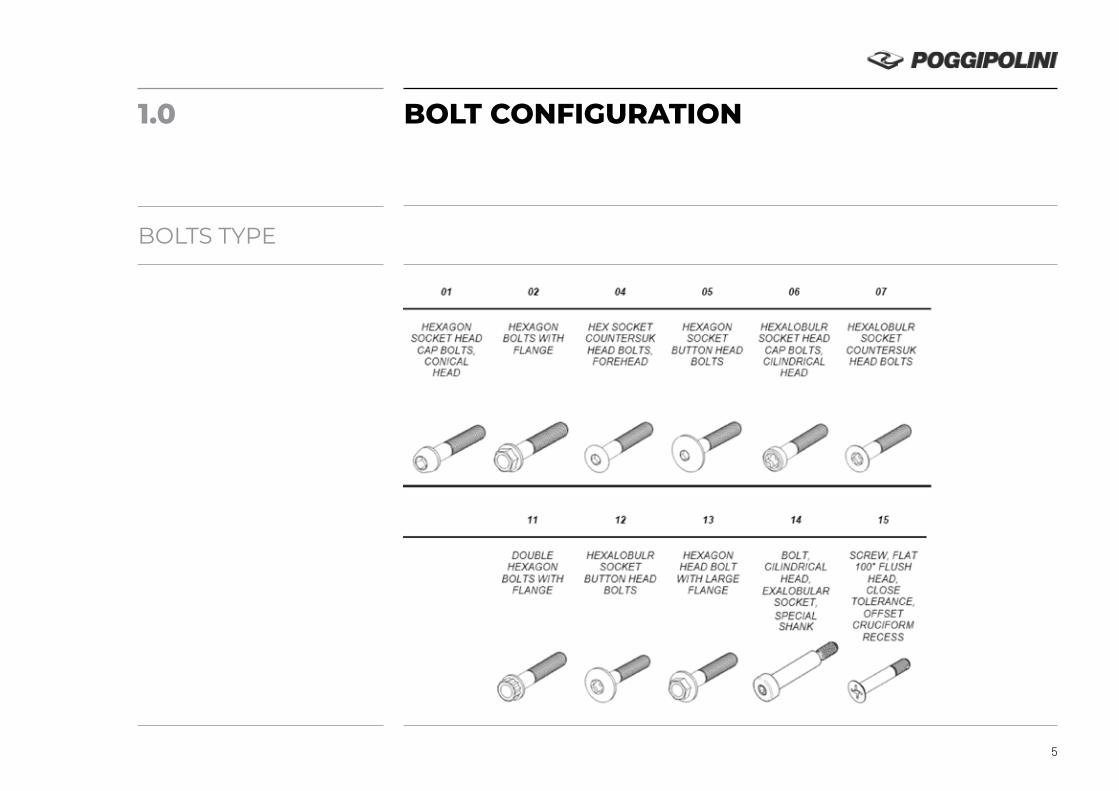
BOLTS TYPE
BOLT CONFIGURATION
5

BOLT DIMENSIONS
6
Length CHOOSE THE LENGTH FROM MINIMUN UP TO MAXIMUN DIMENSIONS, SEE (D) TABLE 2
b, ds, ls, and all dimensions not in view, SEE THE CODE TABLE BOLT TYPE CHOSEN AND EXAMINE THE LINE OF THE RELEVANT THREAD
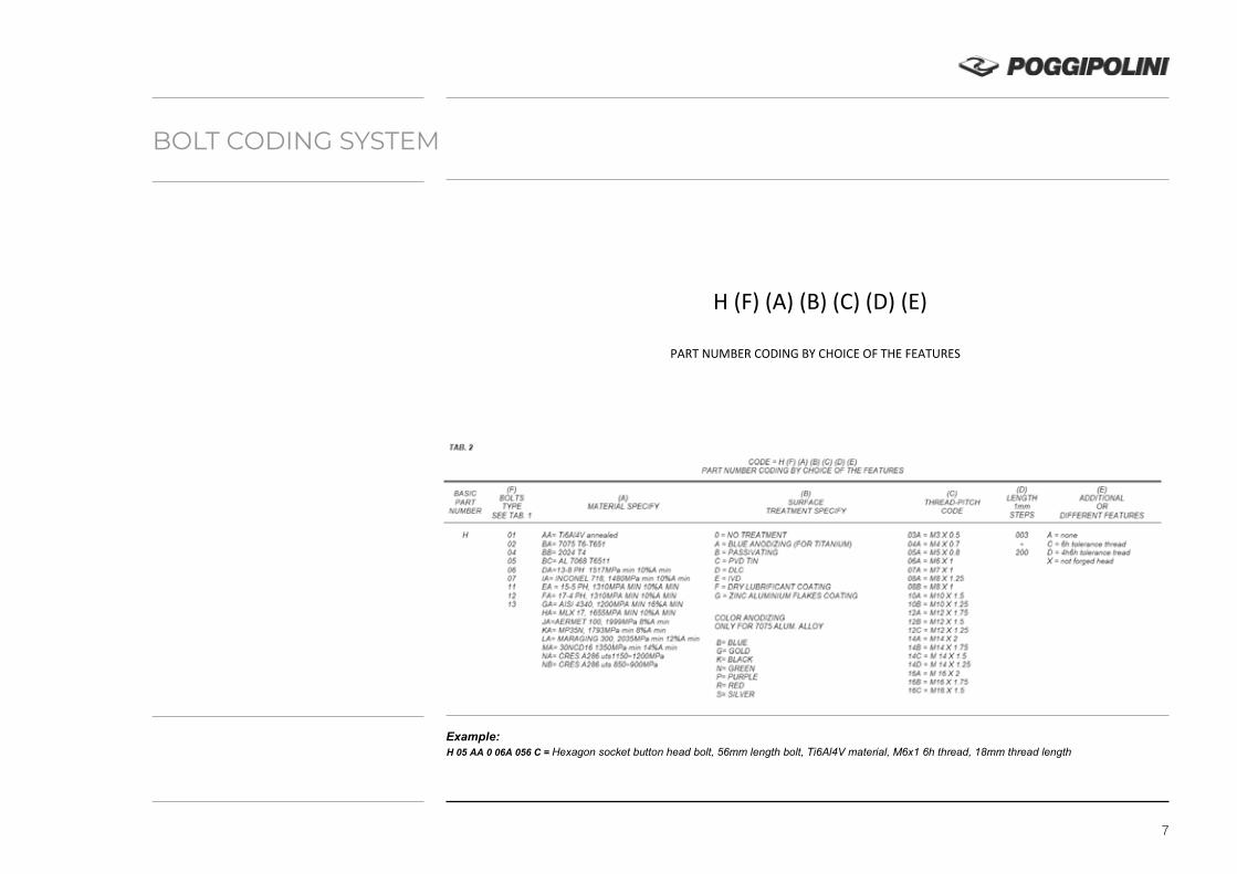
H (F) (A) (B) (C) (D) (E)
PART NUMBER CODING BY CHOICE OF THE FEATURES
Example: H 05 AA 0 06A 056 C = Hexagon socket button head bolt, 56mm length bolt, Ti6Al4V material, M6x1 6h thread, 18mm thread length
BOLT CODING SYSTEM
7

DRAWING NUMBER – CODICE DOCUMENTO ISSUE DATE – DATA RILASCIO REVISIONS - REVISIONI
HXX - - X - - - XXX - 14-06-2016
TOLERANCES UNLESS OTHERWISE NOTED
CUSTOMIZE BOLTS CONFIGURATION TABLE
PART NUMBER SEE TABLE 2
H (F)(A)(B)(C)(D)(E) PAGE 1 OF 2
METRIC DIMENSIONS LINEAR ±0.1 ANGULAR ±2°
ROUGHNESS Ra 3.2
INFORMATION ON THIS DOCUMENT IS PROPRIETARY TO POGGIPOLINI, AND SHALL NOT BE COPIED IN WHOLE OR IN PART WITHOUT WRITTEN PERMISSION OF POGGIPOLINI
TAB. 1
BOLTS TYPE CODE
01 02 04 05 06 07 11 12 13 14 15
HEXAGON
SOCKET HEAD CAP BOLTS,
CONICAL HEAD
HEXAGON
BOLTS WITH FLANGE
HEX SOCKET
COUNTERSUK HEAD BOLTS, FOREHEAD
HEXAGON SOCKET
BUTTON HEAD BOLTS
HEXALOBULR SOCKET HEAD
CAP BOLTS, CILINDRICAL
HEAD
HEXALOBULR
SOCKET COUNTERSUK HEAD BOLTS
DOUBLE
HEXAGON BOLTS WITH
FLANGE
HEXALOBULR
SOCKET BUTTON HEAD
BOLTS
HEXAGON
HEAD BOLT WITH LARGE
FLANGE
BOLT,
CILINDRICAL HEAD,
EXALOBULAR SOCKET, SPECIAL SHANK
SCREW, FLAT 100° FLUSH
HEAD, CLOSE
TOLERANCE, OFFSET
CRUCIFORM RECESS
length b, ds, ls, and all dimensions not in view,
CHOOSE THE LENGTH FROM MINIMUN UP TO MAXIMUN, SEE (D) TABLE 2 SEE THE CODE TABLE BOLT TYPE CHOSEN AND EXAMINE THE LINE OF THE RELEVANT THREAD
DRAWING NUMBER – CODICE DOCUMENTO ISSUE DATE – DATA RILASCIO REVISIONS - REVISIONI
HXX - - X - - - XXX - 14-06-2016
TOLERANCES UNLESS OTHERWISE NOTED
CUSTOMIZE BOLTS CONFIGURATION TABLE
PART NUMBER SEE TABLE 2
H (F)(A)(B)(C)(D)(E) PAGE 2 OF 2
METRIC DIMENSIONS LINEAR ±0.1 ANGULAR ±2°
ROUGHNESS Ra 3.2
INFORMATION ON THIS DOCUMENT IS PROPRIETARY TO POGGIPOLINI, AND SHALL NOT BE COPIED IN WHOLE OR IN PART WITHOUT WRITTEN PERMISSION OF POGGIPOLINI
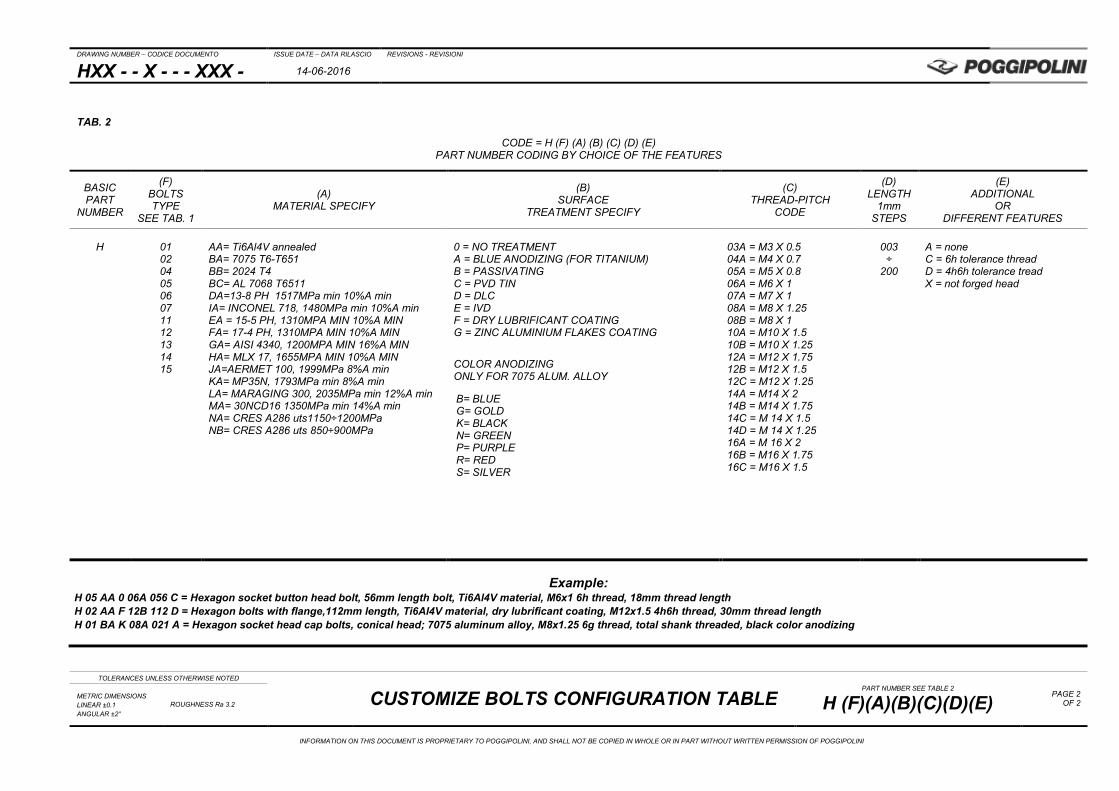
TAB. 2
CODE = H (F) (A) (B) (C) (D) (E) PART NUMBER CODING BY CHOICE OF THE FEATURES
BASIC PART
NUMBER
(F) BOLTS TYPE
SEE TAB. 1
(A) MATERIAL SPECIFY
(B) SURFACE
TREATMENT SPECIFY
(C) THREAD-PITCH
CODE
(D) LENGTH
1mm STEPS
(E) ADDITIONAL
OR DIFFERENT FEATURES
H
01 02 04 05 06 07 11 12 13 14 15
AA= Ti6Al4V annealed BA= 7075 T6-T651 BB= 2024 T4 BC= AL 7068 T6511 DA=13-8 PH 1517MPa min 10%A min IA= INCONEL 718, 1480MPa min 10%A min EA = 15-5 PH, 1310MPA MIN 10%A MIN FA= 17-4 PH, 1310MPA MIN 10%A MIN GA= AISI 4340, 1200MPA MIN 16%A MIN HA= MLX 17, 1655MPA MIN 10%A MIN JA=AERMET 100, 1999MPa 8%A min KA= MP35N, 1793MPa min 8%A min LA= MARAGING 300, 2035MPa min 12%A min MA= 30NCD16 1350MPa min 14%A min NA= CRES A286 uts1150÷1200MPa NB= CRES A286 uts 850÷900MPa
0 = NO TREATMENT A = BLUE ANODIZING (FOR TITANIUM) B = PASSIVATING C = PVD TIN D = DLC E = IVD F = DRY LUBRIFICANT COATING G = ZINC ALUMINIUM FLAKES COATING
COLOR ANODIZING ONLY FOR 7075 ALUM. ALLOY
B= BLUE G= GOLD K= BLACK N= GREEN P= PURPLE R= RED S= SILVER
03A = M3 X 0.5 04A = M4 X 0.7 05A = M5 X 0.8 06A = M6 X 1 07A = M7 X 1 08A = M8 X 1.25 08B = M8 X 1 10A = M10 X 1.5 10B = M10 X 1.25 12A = M12 X 1.75 12B = M12 X 1.5 12C = M12 X 1.25 14A = M14 X 2 14B = M14 X 1.75 14C = M 14 X 1.5 14D = M 14 X 1.25 16A = M 16 X 2 16B = M16 X 1.75 16C = M16 X 1.5
003 ÷
200
A = none C = 6h tolerance thread D = 4h6h tolerance tread X = not forged head
Example: H 05 AA 0 06A 056 C = Hexagon socket button head bolt, 56mm length bolt, Ti6Al4V material, M6x1 6h thread, 18mm thread length H 02 AA F 12B 112 D = Hexagon bolts with flange,112mm length, Ti6Al4V material, dry lubrificant coating, M12x1.5 4h6h thread, 30mm thread length H 01 BA K 08A 021 A = Hexagon socket head cap bolts, conical head; 7075 aluminum alloy, M8x1.25 6g thread, total shank threaded, black color anodizing
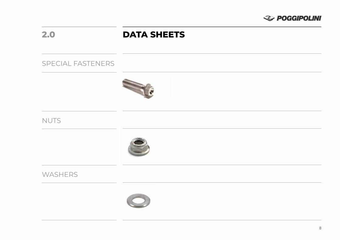
2.0
SPECIAL FASTENERS
NUTS
WASHERS
DATA SHEETS
8
DRAWING NUMBER – CODICE DOCUMENTO ISSUE DATE – DATA RILASCIO REVISIONS - REVISIONI
H01XX-XXX- - -X 09-06-2016
TOLERANCES UNLESS OTHERWISE NOTED
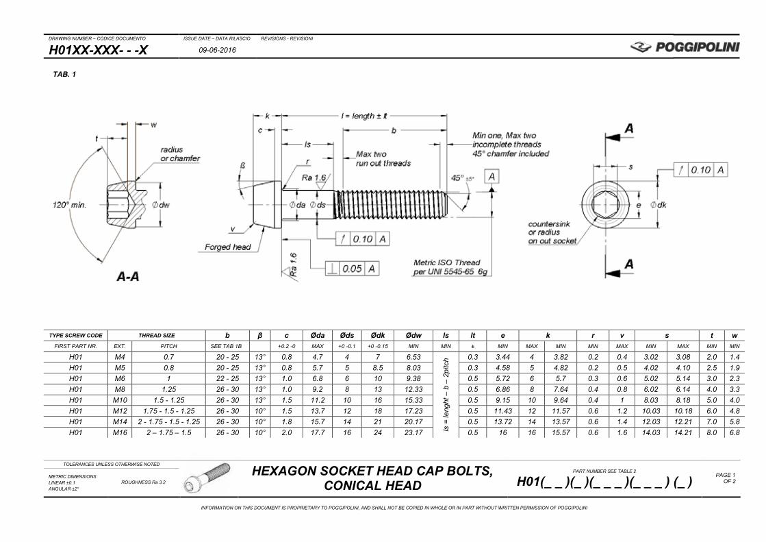
HEXAGON SOCKET HEAD CAP BOLTS, CONICAL HEAD
PART NUMBER SEE TABLE 2
H01(_ _ )(_ )(_ _ _ )(_ _ _ ) (_ ) PAGE 1
OF 2 METRIC DIMENSIONS LINEAR ±0.1 ANGULAR ±2°
ROUGHNESS Ra 3.2
INFORMATION ON THIS DOCUMENT IS PROPRIETARY TO POGGIPOLINI, AND SHALL NOT BE COPIED IN WHOLE OR IN PART WITHOUT WRITTEN PERMISSION OF POGGIPOLINI
TYPE SCREW CODE THREAD SIZE b β c Øda Øds Ødk Ødw ls lt e k r v s t w FIRST PART NR. EXT. PITCH SEE TAB 1B +0.2 -0 MAX +0 -0.1 +0 -0.15 MIN MIN ± MIN MAX MIN MIN MAX MIN MAX MIN MIN
H01 M4 0.7 20 - 25 13° 0.8 4.7 4 7 6.53
ls =
leng
ht –
b –
2pi
tch 0.3 3.44 4 3.82 0.2 0.4 3.02 3.08 2.0 1.4
H01 M5 0.8 20 - 25 13° 0.8 5.7 5 8.5 8.03 0.3 4.58 5 4.82 0.2 0.5 4.02 4.10 2.5 1.9 H01 M6 1 22 - 25 13° 1.0 6.8 6 10 9.38 0.5 5.72 6 5.7 0.3 0.6 5.02 5.14 3.0 2.3 H01 M8 1.25 26 - 30 13° 1.0 9.2 8 13 12.33 0.5 6.86 8 7.64 0.4 0.8 6.02 6.14 4.0 3.3 H01 M10 1.5 - 1.25 26 - 30 13° 1.5 11.2 10 16 15.33 0.5 9.15 10 9.64 0.4 1 8.03 8.18 5.0 4.0 H01 M12 1.75 - 1.5 - 1.25 26 - 30 10° 1.5 13.7 12 18 17.23 0.5 11.43 12 11.57 0.6 1.2 10.03 10.18 6.0 4.8 H01 M14 2 - 1.75 - 1.5 - 1.25 26 - 30 10° 1.8 15.7 14 21 20.17 0.5 13.72 14 13.57 0.6 1.4 12.03 12.21 7.0 5.8 H01 M16 2 – 1.75 – 1.5 26 - 30 10° 2.0 17.7 16 24 23.17 0.5 16 16 15.57 0.6 1.6 14.03 14.21 8.0 6.8
TAB. 1

DRAWING NUMBER – CODICE DOCUMENTO ISSUE DATE – DATA RILASCIO REVISIONS - REVISIONI
H01XX-XXX- - -X 09-06-2016
TOLERANCES UNLESS OTHERWISE NOTED
HEXAGON SOCKET HEAD CAP BOLTS, CONICAL HEAD
PART NUMBER SEE TABLE 2
H01(_ _ )(_ )(_ _ _ )(_ _ _ ) (_ ) PAGE 2
OF 2 METRIC DIMENSIONS LINEAR ±0.1 ANGULAR ±2°
ROUGHNESS Ra 3.2
INFORMATION ON THIS DOCUMENT IS PROPRIETARY TO POGGIPOLINI, AND SHALL NOT BE COPIED IN WHOLE OR IN PART WITHOUT WRITTEN PERMISSION OF POGGIPOLINI
CODE EXAMPLES:
PART NUMBER: H01 AA 0 10B 035 A PART NUMBER: H01 BA K 08A 020 X No Additional Features not forged head
“l” BOLT LENGTH 35mm; “b” 30mm; “ls” 2.5mm “l” BOLT LENGTH 20mm all threaded shank
THREAD CODE (M10 x 1.25) THREAD CODE (M8 x 1.25)
NO TREATMENT BLACK ANODIZING
Ti6Al4V MATERIAL AL 7075 T6
HEX. SOCKET HEAD CAP BOLTS, CONICAL HEAD HEX. SOCKET HEAD CAP BOLTS, CONICAL HEAD
TAB. 2 CODE = H01 (A) (B) (C) (D) (E)
PART NUMBER CODING BY CHOICE OF THE FEATURES
BASIC PART NUMBER
(A) MATERIAL SPECIFY
(B) SURFACE
TREATMENT SPECIFY
(C) THREAD CODE
(D) LENGTH
mm
(E) ADDITIONAL FEATURES
H01
AA= Ti6Al4V annealed BA= 7075 T6-T651
0 = NO TREATMENT A = BLUE ANODIZING
(FOR TITANIUM) B = PASSIVATING C = PVD TIN D = DLC E = IVD F = DRY LUBRIFICANT
COATING G = ZINC ALUMINIUM
FLAKES COATING
04A = M4 x 0.7 05A = M5 x 0.8 06A = M6 x 1 07A = M7 x 1 08A = M8 x 1.25 10A = M10 x 1.5 10B = M10 x 1.25 12A = M12 x 1.75 12B = M12 x 1.5 12C = M12 x 1.25 14A = M14 x 2 14B = M14 x 1.75 14C = M14 x 1.5 14D = M14 x 1.25 16A = M16 x 2 16B = M16 x 1.75 16C = M16 x 1.5
010 015 020 025 030 035 040 045 050 ÷
140
A = none C = 6h thread D = 4h6h thread X = not forged head
COLOR ANODIZING ONLY FOR
7075 ALUM. ALLOY
B= BLUE G= GOLD K= BLACK N= GREEN P= PURPLE R= RED S= SILVER
TAB. 1B
“l“ LENGTH “b” THREAD LENGTH M4 M5 M6 M8 M10 M12 M14 M16
10 ALL THREADED SHANK 15
20 25 20 20 22 22 30 20 20 22 25 26 26 26 26 35 20 20 25 25 30 30 30 30 40 25 25 25 25 30 30 30 30 45 25 25 25 25 30 30 30 30 50 25 25 25 25 30 30 30 30 ÷ ÷ ÷ ÷ ÷ ÷ ÷ ÷ ÷
140 25 25 25 25 30 30 30 30
DRAWING NUMBER – CODICE DOCUMENTO ISSUE DATE – DATA RILASCIO REVISIONS - REVISIONI
H02XX-XXX- - -X 05-05-2016
TOLERANCES UNLESS OTHERWISE NOTED
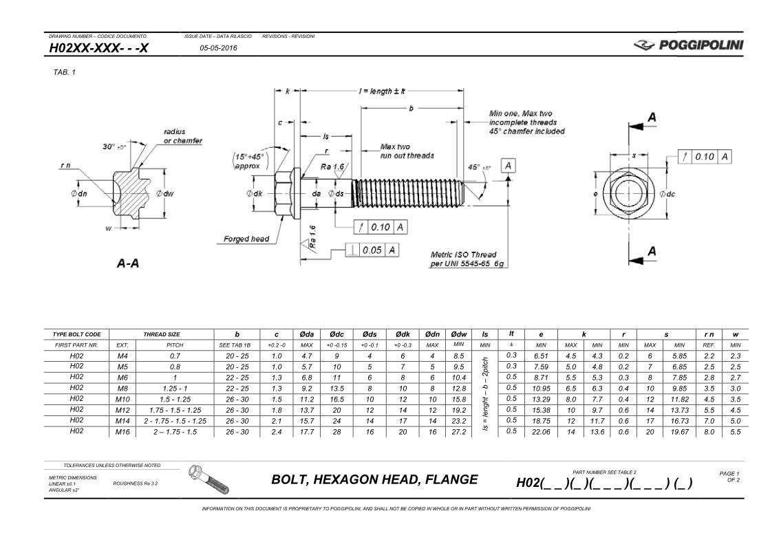
BOLT, HEXAGON HEAD, FLANGE PART NUMBER SEE TABLE 2
H02(_ _ )(_ )(_ _ _ )(_ _ _ ) (_ ) PAGE 1
OF 2
METRIC DIMENSIONS LINEAR ±0.1 ANGULAR ±2°
ROUGHNESS Ra 3.2
INFORMATION ON THIS DOCUMENT IS PROPRIETARY TO POGGIPOLINI, AND SHALL NOT BE COPIED IN WHOLE OR IN PART WITHOUT WRITTEN PERMISSION OF POGGIPOLINI
TYPE BOLT CODE THREAD SIZE b c Øda Ødc Øds Ødk Ødn Ødw ls lt e k r s r n w FIRST PART NR. EXT. PITCH SEE TAB 1B +0.2 -0 MAX +0 -0.15 +0 -0.1 +0 -0.3 MAX MIN MIN ± MIN MAX MIN MIN MAX MIN REF. MIN
H02 M4 0.7 20 - 25 1.0 4.7 9 4 6 4 8.5
ls =
leng
ht –
b –
2pi
tch 0.3 6.51 4.5 4.3 0.2 6 5.85 2.2 2.3
H02 M5 0.8 20 - 25 1.0 5.7 10 5 7 5 9.5 0.3 7.59 5.0 4.8 0.2 7 6.85 2.5 2.5 H02 M6 1 22 - 25 1.3 6.8 11 6 8 6 10.4 0.5 8.71 5.5 5.3 0.3 8 7.85 2.8 2.7 H02 M8 1.25 - 1 22 - 25 1.3 9.2 13.5 8 10 8 12.8 0.5 10.95 6.5 6.3 0.4 10 9.85 3.5 3.0 H02 M10 1.5 - 1.25 26 - 30 1.5 11.2 16.5 10 12 10 15.8 0.5 13.29 8.0 7.7 0.4 12 11.82 4.5 3.5 H02 M12 1.75 - 1.5 - 1.25 26 - 30 1.8 13.7 20 12 14 12 19.2 0.5 15.38 10 9.7 0.6 14 13.73 5.5 4.5 H02 M14 2 - 1.75 - 1.5 - 1.25 26 - 30 2.1 15.7 24 14 17 14 23.2 0.5 18.75 12 11.7 0.6 17 16.73 7.0 5.0 H02 M16 2 – 1.75 - 1.5 26 - 30 2.4 17.7 28 16 20 16 27.2 0.5 22.06 14 13.6 0.6 20 19.67 8.0 5.5
TAB. 1
DRAWING NUMBER – CODICE DOCUMENTO ISSUE DATE – DATA RILASCIO REVISIONS - REVISIONI
H02XX-XXX- - -X 05-05-2016
TOLERANCES UNLESS OTHERWISE NOTED
BOLT, HEXAGON HEAD, FLANGE PART NUMBER SEE TABLE 2
H02(_ _ )(_ )(_ _ _ )(_ _ _ ) (_ ) PAGE 2
OF 2
METRIC DIMENSIONS LINEAR ±0.1 ANGULAR ±2°
ROUGHNESS Ra 3.2
INFORMATION ON THIS DOCUMENT IS PROPRIETARY TO POGGIPOLINI, AND SHALL NOT BE COPIED IN WHOLE OR IN PART WITHOUT WRITTEN PERMISSION OF POGGIPOLINI
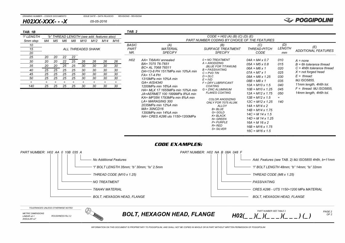
CODE EXAMPLES:
PART NUMBER: H02 AA 0 10B 035 A PART NUMBER: H02 NA B 08A 048 F
No Additional Features Add. Features (see TAB. 2) MJ ISO5855 4h6h, b=11mm
“l” BOLT LENGTH 35mm; “b” 30mm; “ls” 2.5mm “l” BOLT LENGTH 48mm; “b” 14mm; “ls” 32mm
THREAD CODE (M10 x 1.25) THREAD CODE (M8 x 1.25)
NO TREATMENT PASSIVATING
Ti6Al4V MATERIAL CRES A286 - UTS 1150÷1200 MPa MATERIAL
BOLT, HEXAGON HEAD, FLANGE BOLT, HEXAGON HEAD, FLANGE
TAB. 2 CODE = H02 (A) (B) (C) (D) (E)
PART NUMBER CODING BY CHOICE OF THE FEATURES BASIC PART NR.
(A) MATERIAL SPECIFY
(B) SURFACE TREATMENT
SPECIFY
(C) THREAD-PITCH
CODE
(D) LENGTH
mm
(E) ADDITIONAL FEATURES
H02
AA= Ti6Al4V annealed BA= 7075 T6-T651 BC= AL 7068 T6511 DA=13-8 PH 1517MPa min 10%A min FA= 17-4 PH 1310MPa min 10%A min GA= AISI4340 1200MPa min 16%A min HA= MLX 17 1655MPa min 10%A min JA=AERMET 100 1999MPa 8%A min KA= MP35N 1793MPa min 8%A min LA= MARAGING 300 2035MPa min 12%A min MA= 30NCD16 1350MPa min 14%A min NA= CRES A286 uts 1150÷1200MPa
0 = NO TREATMENT A = ANODIZING
(BLUE FOR TITANIUM) B = PASSIVATING C = PVD TIN D = DLC E = IVD F = DRY LUBRIFICANT
COATING G = ZINC ALUMINIUM
FLAKES COATING
COLOR ANODIZING ONLY FOR 7075 ALUM.
ALLOY B= BLUE G= GOLD K= BLACK N= GREEN P= PURPLE R= RED S= SILVER
04A = M4 x 0.7 05A = M5 x 0.8 06A = M6 x 1 07A = M7 x 1 08A = M8 x 1.25 08B = M8 x 1 10A = M10 x 1.5 10B = M10 x 1.25 12A = M12 x 1.75 12B = M12 x 1.5 12C = M12 x 1.25 14A = M14 x 2 14B = M14 x 1.75 14C = M 14 x 1.5 14D = M 14 x 1.25 16A = M 16 x 2 16B = M16 x 1.75 16C = M16 x 1.5
010 015 020 025 030 035 040 045 050 ÷ 140
A = none B = 6h tolerance thread C = 4h6h tolerance thread X = not forged head E = thread: MJ ISO5855, 11mm length, 4h6h tol. F = thread: MJ ISO5855, 14mm length, 4h6h tol.
TAB. 1B “l“ LENGTH 5mm step
“b” THREAD LENGTH (see add. features also) M4 M5 M6 M8 M10 M12 M14 M16
10 ALL THREADED SHANK 15
20 25 20 20 22 22 30 20 20 22 25 26 26 26 26 35 20 20 25 25 30 30 30 30 40 25 25 25 25 30 30 30 30 45 25 25 25 25 30 30 30 30 50 25 25 25 25 30 30 30 30 ÷ ÷ ÷ ÷ ÷ ÷ ÷ ÷ ÷
140 25 25 25 25 30 30 30 30
DRAWING NUMBER – CODICE DOCUMENTO ISSUE DATE – DATA RILASCIO REVISIONS - REVISIONI
H04XX-XXX- - -X 10-06-2016
TOLERANCES UNLESS OTHERWISE NOTED
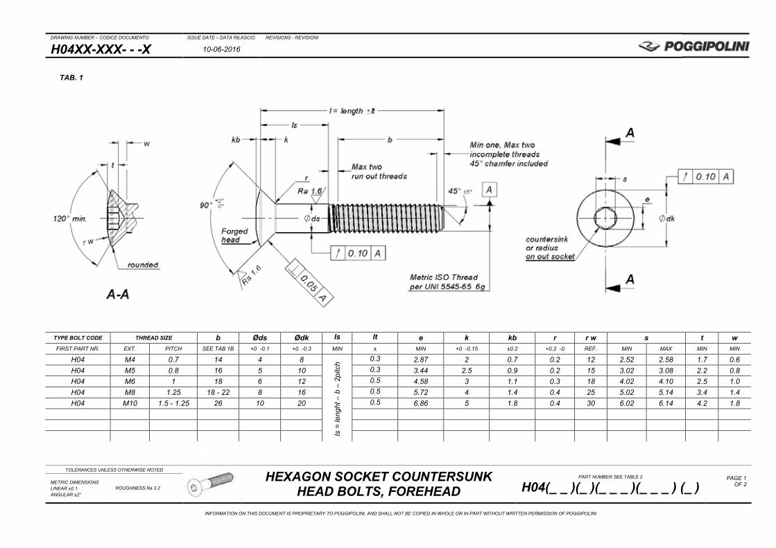
HEXAGON SOCKET COUNTERSUNK HEAD BOLTS, FOREHEAD
PART NUMBER SEE TABLE 2
H04(_ _ )(_ )(_ _ _ )(_ _ _ ) (_ ) PAGE 1
OF 2
METRIC DIMENSIONS LINEAR ±0.1 ANGULAR ±2°
ROUGHNESS Ra 3.2
INFORMATION ON THIS DOCUMENT IS PROPRIETARY TO POGGIPOLINI, AND SHALL NOT BE COPIED IN WHOLE OR IN PART WITHOUT WRITTEN PERMISSION OF POGGIPOLINI
TAB. 1
TYPE BOLT CODE THREAD SIZE b Øds Ødk ls lt e k kb r r w s t w FIRST PART NR. EXT. PITCH SEE TAB 1B +0 -0.1 +0 -0.3 MIN ± MIN +0 -0.15 ±0.2 +0.2 -0 REF. MIN MAX MIN MIN
H04 M4 0.7 14 4 8
ls =
leng
ht –
b –
2pi
tch
0.3 2.87 2 0.7 0.2 12 2.52 2.58 1.7 0.6 H04 M5 0.8 16 5 10 0.3 3.44 2.5 0.9 0.2 15 3.02 3.08 2.2 0.8 H04 M6 1 18 6 12 0.5 4.58 3 1.1 0.3 18 4.02 4.10 2.5 1.0 H04 M8 1.25 18 - 22 8 16 0.5 5.72 4 1.4 0.4 25 5.02 5.14 3.4 1.4 H04 M10 1.5 - 1.25 26 10 20 0.5 6.86 5 1.8 0.4 30 6.02 6.14 4.2 1.8
DRAWING NUMBER – CODICE DOCUMENTO ISSUE DATE – DATA RILASCIO REVISIONS - REVISIONI
H04XX-XXX- - -X 10-06-2016
TOLERANCES UNLESS OTHERWISE NOTED
HEXAGON SOCKET COUNTERSUNK HEAD BOLTS, FOREHEAD
PART NUMBER SEE TABLE 2
H04(_ _ )(_ )(_ _ _ )(_ _ _ ) (_ ) PAGE 2
OF 2
METRIC DIMENSIONS LINEAR ±0.1 ANGULAR ±2°
ROUGHNESS Ra 3.2
INFORMATION ON THIS DOCUMENT IS PROPRIETARY TO POGGIPOLINI, AND SHALL NOT BE COPIED IN WHOLE OR IN PART WITHOUT WRITTEN PERMISSION OF POGGIPOLINI
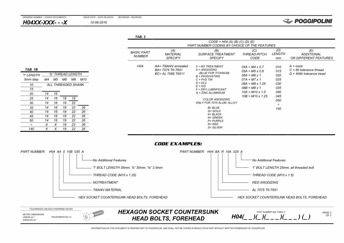
CODE EXAMPLES:
PART NUMBER: H04 AA 0 10B 035 A PART NUMBER: H04 BA R 10A 025 A No Additional Features No Additional Features
“l” BOLT LENGTH 35mm; “b” 30mm; “ls” 2.5mm “l” BOLT LENGTH 25mm; all threaded bolt
THREAD CODE (M10 x 1.25) THREAD CODE (M10 x 1.5)
NOTREATMENT RED ANODIZING
Ti6Al4V MATERIAL AL 7075 T6-T651
HEX SOCKET COUNTERSUNK HEAD BOLTS, FOREHEAD HEX SOCKET COUNTERSUNK HEAD BOLTS, FOREHEAD
TAB. 2 CODE = H04 (A) (B) (C) (D) (E)
PART NUMBER CODING BY CHOICE OF THE FEATURES
BASIC PART NUMBER
(A) MATERIAL SPECIFY
(B) SURFACE TREATMENT
SPECIFY
(C) THREAD-PITCH
CODE
(D) LENGTH
mm
(E) ADDITIONAL
OR DIFFERENT FEATURES
H04 AA= Ti6Al4V annealed BA= 7075 T6-T651 BC= AL 7068 T6511
0 = NO TREATMENT A = ANODIZING
(BLUE FOR TITANIUM) B = PASSIVATING C = PVD TIN D = DLC E = IVD F = DRY LUBRIFICANT G = ZINC ALUMINIUM
04A = M4 x 0.7 05A = M5 x 0.8 06A = M6 x 1 07A = M7 x 1 08A = M8 x 1.25 08B = M8 x 1 10A = M10 x 1.5 10B = M10 x 1.25
010 015 020 025 030 035 040 045 050 ÷
140
A = none C = 6h tolerance thread D = 4h6h tolerance tread
COLOR ANODIZING ONLY FOR 7075 ALUM. ALLOY
B= BLUE G= GOLD K= BLACK N= GREEN P= PURPLE R= RED S= SILVER
TAB. 1B
“l“ LENGTH 5mm step
“b” THREAD LENGTH M4 M5 M6 M8 M10
10 ALL THREADED SHANK 15 20 14 16 25 14 16 18 18
30 14 16 18 22 35 14 16 18 22 26 40 14 16 18 22 26 45 14 16 18 22 26 50 14 16 18 22 26 ÷ X X 18 22 26
140 X X 18 22 26
DRAWING NUMBER – CODICE DOCUMENTO ISSUE DATE – DATA RILASCIO REVISIONS - REVISIONI
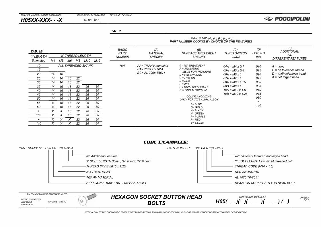
H05XX-XXX- - -X 10-06-2016
TOLERANCES UNLESS OTHERWISE NOTED
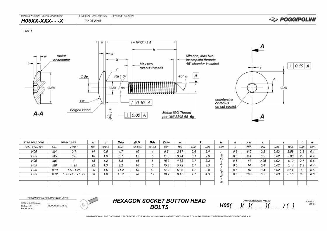
HEXAGON SOCKET BUTTON HEAD BOLTS
PART NUMBER SEE TABLE 2
H05(_ _ )(_ )(_ _ _ )(_ _ _ ) (_ ) PAGE 1
OF 2
METRIC DIMENSIONS LINEAR ±0.1 ANGULAR ±2°
ROUGHNESS Ra 3.2
INFORMATION ON THIS DOCUMENT IS PROPRIETARY TO POGGIPOLINI, AND SHALL NOT BE COPIED IN WHOLE OR IN PART WITHOUT WRITTEN PERMISSION OF POGGIPOLINI
TYPE BOLT CODE THREAD SIZE b c Øda Ødk Øds Ødw e k ls lt r w r s t w FIRST PART NR. EXT. PITCH MIN +0.2 -0 MAX +0 -0.15 +0 -0.1 MIN MIN MAX MIN MIN ± REF. MIN MIN MAX MAX MIN
H05 M4 0.7 14 0.5 4.7 10 4 9.5 2.87 2.6 2.4
ls =
leng
ht –
b –
2pi
tch 0.3 6.9 0.2 2.52 2.58 2.3 0.1
H05 M5 0.8 16 1.0 5.7 12 5 11.3 3.44 3.1 2.9 0.3 9.4 0.2 3.02 3.08 2.5 0.4 H05 M6 1 18 1.2 6.8 16 6 15.3 4.58 3.7 3.3 0.5 14 0.25 4.02 4.10 2.7 0.6 H05 M8 1.25 22 1.3 9.2 16 8 15.3 5.72 3.7 3.3 0.5 14 0.4 5.02 5.14 2.9 0.4 H05 M10 1.5 - 1.25 26 1.6 11.2 18 10 17.2 6.86 4.2 3.8 0.5 16 0.4 6.02 6.14 3.2 0.6 H05 M12 1.75 - 1.5 - 1.25 30 1.8 13.7 20 12 19.2 9.15 4.7 4.3 0.5 16.5 0.5 8.03 8.18 3.5 0.8
TAB. 1
DRAWING NUMBER – CODICE DOCUMENTO ISSUE DATE – DATA RILASCIO REVISIONS - REVISIONI
H05XX-XXX- - -X 10-06-2016
TOLERANCES UNLESS OTHERWISE NOTED
HEXAGON SOCKET BUTTON HEAD BOLTS
PART NUMBER SEE TABLE 2
H05(_ _ )(_ )(_ _ _ )(_ _ _ ) (_ ) PAGE 2
OF 2
METRIC DIMENSIONS LINEAR ±0.1 ANGULAR ±2°
ROUGHNESS Ra 3.2
INFORMATION ON THIS DOCUMENT IS PROPRIETARY TO POGGIPOLINI, AND SHALL NOT BE COPIED IN WHOLE OR IN PART WITHOUT WRITTEN PERMISSION OF POGGIPOLINI
CODE EXAMPLES:
PART NUMBER: H05 AA 0 10B 035 A PART NUMBER: H05 BA R 10A 025 X No Additional Features with “different feature”: not forged head
“l” BOLT LENGTH 35mm; “b” 26mm; “ls” 6.5mm “l” BOLT LENGTH 25mm; all threaded bolt
THREAD CODE (M10 x 1.25) THREAD CODE (M10 x 1.5)
NO TREATMENT RED ANODIZING
Ti6Al4V MATERIAL AL 7075 T6-T651
HEXAGON SOCKET BUTTON HEAD BOLT HEXAGON SOCKET BUTTON HEAD BOLT
TAB. 2
CODE = H05 (A) (B) (C) (D) (E) PART NUMBER CODING BY CHOICE OF THE FEATURES
BASIC PART
NUMBER
(A) MATERIAL SPECIFY
(B) SURFACE TREATMENT
SPECIFY
(C) THREAD-PITCH
CODE
(D) LENGTH
mm
(E) ADDITIONAL
OR DIFFERENT FEATURES
H05
AA= Ti6Al4V annealed BA= 7075 T6-T651 BC= AL 7068 T6511
0 = NO TREATMENT A = ANODIZING
(BLUE FOR TITANIUM) B = PASSIVATING C = PVD TIN D = DLC E = IVD F = DRY LUBRIFICANT G = ZINC ALUMINIUM
04A = M4 x 0.7 05A = M5 x 0.8 06A = M6 x 1 07A = M7 x 1 08A = M8 x 1.25 08B = M8 x 1 10A = M10 x 1.5 10B = M10 x 1.25
010 015 020 025 030 035 040 045 050 ÷
140
A = none C = 6h tolerance thread D = 4h6h tolerance tread X = not forged head
COLOR ANODIZING ONLY FOR 7075 ALUM. ALLOY
B= BLUE G= GOLD K= BLACK N= GREEN P= PURPLE R= RED S= SILVER
TAB. 1B “l“ LENGTH 5mm step
“b” THREAD LENGTH M4 M5 M6 M8 M10 M12
10 ALL THREADED SHANK 15 20 14 16 25 14 16 18 22
30 14 16 18 22 35 14 16 18 22 26 30 40 14 16 18 22 26 30 45 14 16 18 22 26 30 50 14 16 18 22 26 30 55 X 16 18 22 26 30 60 X 16 18 22 26 30 ÷ X X 18 22 26 30
100 X X 18 22 26 30 ÷ X X X 22 26 30
140 X X X 22 26 30
DRAWING NUMBER – CODICE DOCUMENTO ISSUE DATE – DATA RILASCIO REVISIONS - REVISIONI
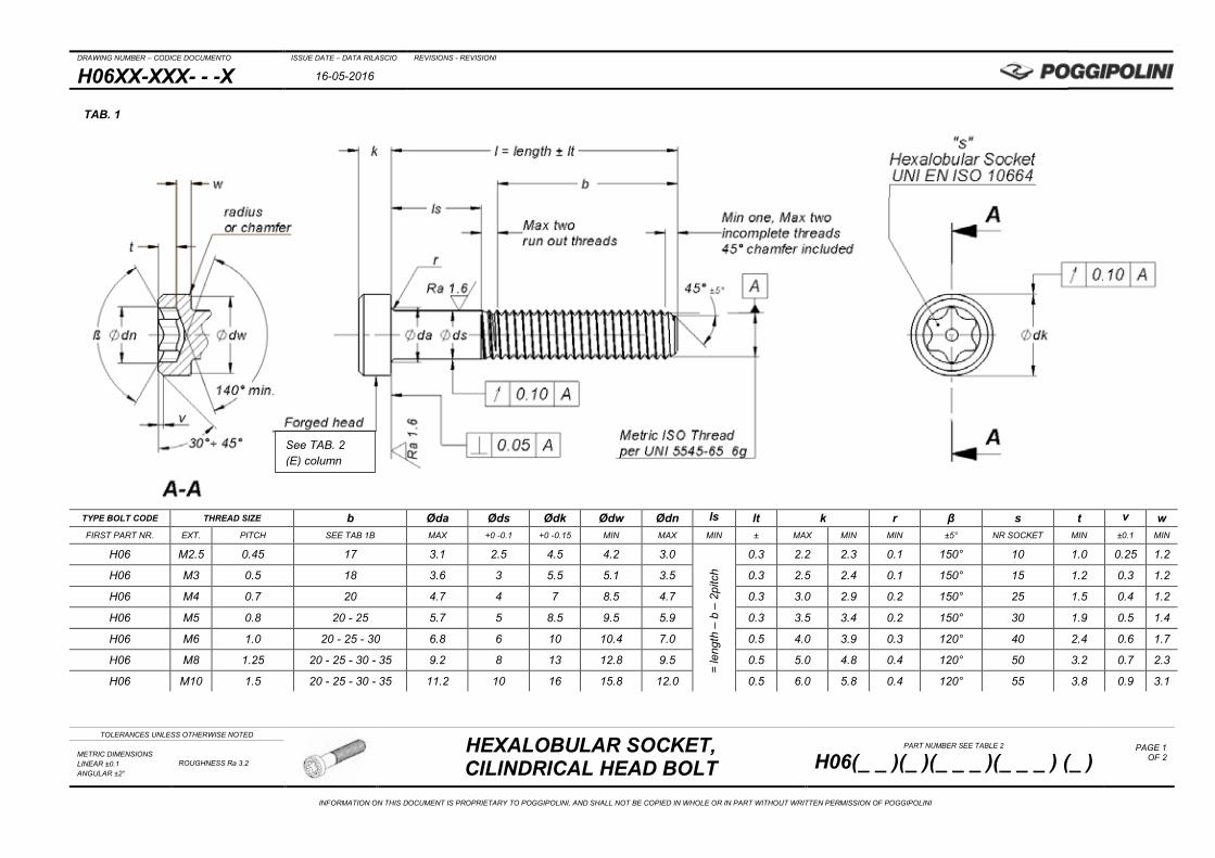
H06XX-XXX- - -X 16-05-2016
TOLERANCES UNLESS OTHERWISE NOTED
HEXALOBULAR SOCKET, CILINDRICAL HEAD BOLT
PART NUMBER SEE TABLE 2
H06(_ _ )(_ )(_ _ _ )(_ _ _ ) (_ ) PAGE 1
OF 2
METRIC DIMENSIONS LINEAR ±0.1 ANGULAR ±2°
ROUGHNESS Ra 3.2
INFORMATION ON THIS DOCUMENT IS PROPRIETARY TO POGGIPOLINI, AND SHALL NOT BE COPIED IN WHOLE OR IN PART WITHOUT WRITTEN PERMISSION OF POGGIPOLINI
TYPE BOLT CODE THREAD SIZE b Øda Øds Ødk Ødw Ødn ls lt k r β s t v w FIRST PART NR. EXT. PITCH SEE TAB 1B MAX +0 -0.1 +0 -0.15 MIN MAX MIN ± MAX MIN MIN ±5° NR SOCKET MIN ±0.1 MIN
H06 M2.5 0.45 17 3.1 2.5 4.5 4.2 3.0
=
leng
th –
b –
2pi
tch
0.3 2.2 2.3 0.1 150° 10 1.0 0.25 1.2
H06 M3 0.5 18 3.6 3 5.5 5.1 3.5 0.3 2.5 2.4 0.1 150° 15 1.2 0.3 1.2
H06 M4 0.7 20 4.7 4 7 8.5 4.7 0.3 3.0 2.9 0.2 150° 25 1.5 0.4 1.2
H06 M5 0.8 20 - 25 5.7 5 8.5 9.5 5.9 0.3 3.5 3.4 0.2 150° 30 1.9 0.5 1.4
H06 M6 1.0 20 - 25 - 30 6.8 6 10 10.4 7.0 0.5 4.0 3.9 0.3 120° 40 2.4 0.6 1.7
H06 M8 1.25 20 - 25 - 30 - 35 9.2 8 13 12.8 9.5 0.5 5.0 4.8 0.4 120° 50 3.2 0.7 2.3
H06 M10 1.5 20 - 25 - 30 - 35 11.2 10 16 15.8 12.0 0.5 6.0 5.8 0.4 120° 55 3.8 0.9 3.1
TAB. 1
See TAB. 2 (E) column
DRAWING NUMBER – CODICE DOCUMENTO ISSUE DATE – DATA RILASCIO REVISIONS - REVISIONI
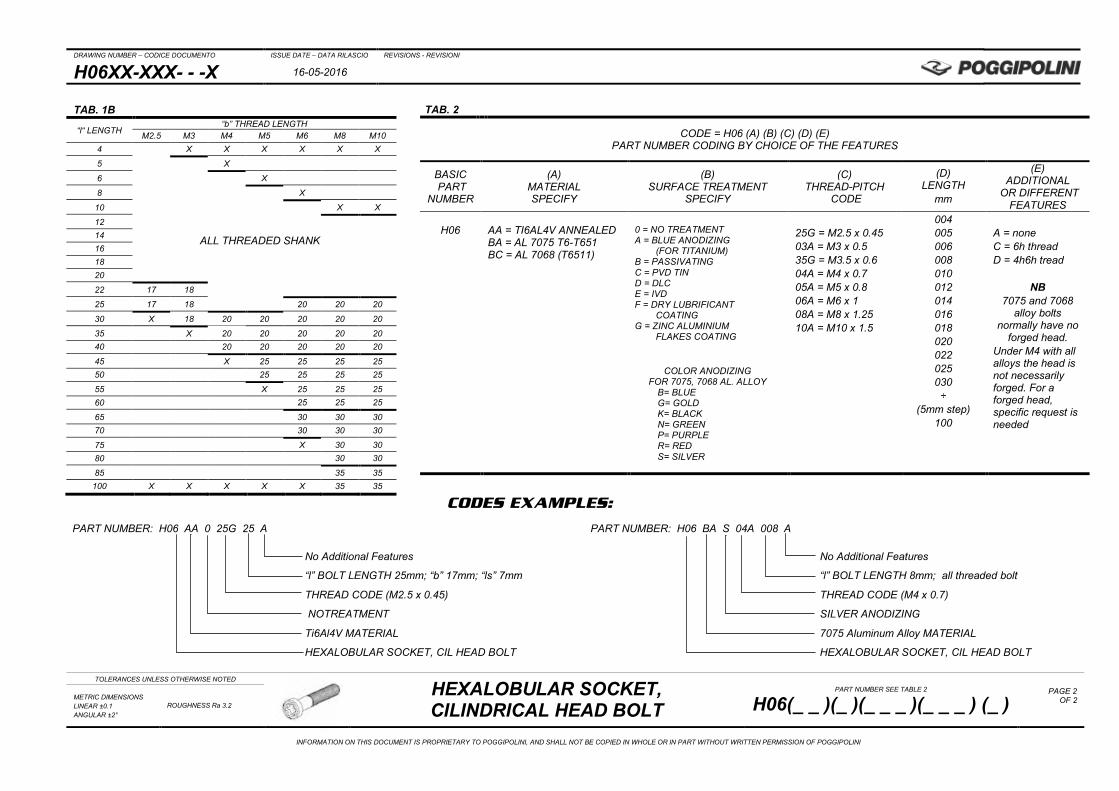
H06XX-XXX- - -X 16-05-2016
TOLERANCES UNLESS OTHERWISE NOTED
HEXALOBULAR SOCKET, CILINDRICAL HEAD BOLT
PART NUMBER SEE TABLE 2
H06(_ _ )(_ )(_ _ _ )(_ _ _ ) (_ ) PAGE 2
OF 2
METRIC DIMENSIONS LINEAR ±0.1 ANGULAR ±2°
ROUGHNESS Ra 3.2
INFORMATION ON THIS DOCUMENT IS PROPRIETARY TO POGGIPOLINI, AND SHALL NOT BE COPIED IN WHOLE OR IN PART WITHOUT WRITTEN PERMISSION OF POGGIPOLINI
CODES EXAMPLES:
PART NUMBER: H06 AA 0 25G 25 A PART NUMBER: H06 BA S 04A 008 A No Additional Features No Additional Features
“l” BOLT LENGTH 25mm; “b” 17mm; “ls” 7mm “l” BOLT LENGTH 8mm; all threaded bolt
THREAD CODE (M2.5 x 0.45) THREAD CODE (M4 x 0.7)
NOTREATMENT SILVER ANODIZING
Ti6Al4V MATERIAL 7075 Aluminum Alloy MATERIAL
HEXALOBULAR SOCKET, CIL HEAD BOLT HEXALOBULAR SOCKET, CIL HEAD BOLT
TAB. 1B
“l“ LENGTH “b” THREAD LENGTH
M2.5 M3 M4 M5 M6 M8 M10 4 X X X X X X
5 X
6 X
8 X
10 X X
12 14 16 18 20
22 17 18
25 17 18 20 20 20
30 X 18 20 20 20 20 20
35 X 20 20 20 20 20 40 20 20 20 20 20
45 X 25 25 25 25 50 25 25 25 25
55 X 25 25 25 60 25 25 25
65 30 30 30 70 30 30 30
75 X 30 30 80 30 30
85 35 35 100 X X X X X 35 35
TAB. 2
CODE = H06 (A) (B) (C) (D) (E) PART NUMBER CODING BY CHOICE OF THE FEATURES
BASIC PART
NUMBER
(A) MATERIAL SPECIFY
(B) SURFACE TREATMENT
SPECIFY
(C) THREAD-PITCH
CODE
(D) LENGTH
mm
(E) ADDITIONAL
OR DIFFERENT FEATURES
H06
AA = TI6AL4V ANNEALED BA = AL 7075 T6-T651 BC = AL 7068 (T6511)
0 = NO TREATMENT A = BLUE ANODIZING
(FOR TITANIUM) B = PASSIVATING C = PVD TIN D = DLC E = IVD F = DRY LUBRIFICANT
COATING G = ZINC ALUMINIUM
FLAKES COATING
25G = M2.5 x 0.45 03A = M3 x 0.5 35G = M3.5 x 0.6 04A = M4 x 0.7 05A = M5 x 0.8 06A = M6 x 1 08A = M8 x 1.25 10A = M10 x 1.5
004 005 006 008 010 012 014 016 018 020 022 025 030 ÷
(5mm step) 100
A = none C = 6h thread D = 4h6h tread
NB 7075 and 7068
alloy bolts normally have no
forged head. Under M4 with all alloys the head is not necessarily forged. For a forged head, specific request is needed
COLOR ANODIZING
FOR 7075, 7068 AL. ALLOY B= BLUE G= GOLD K= BLACK N= GREEN P= PURPLE R= RED S= SILVER
ALL THREADED SHANK
DRAWING NUMBER – CODICE DOCUMENTO ISSUE DATE – DATA RILASCIO REVISIONS - REVISIONI
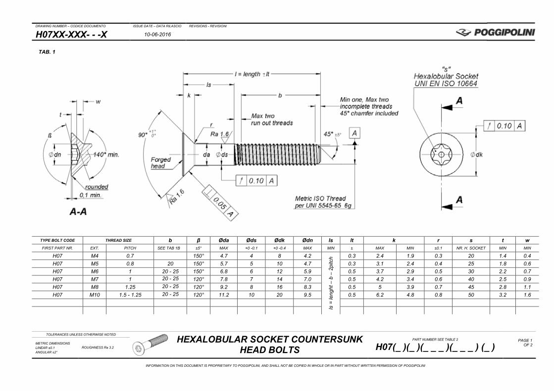
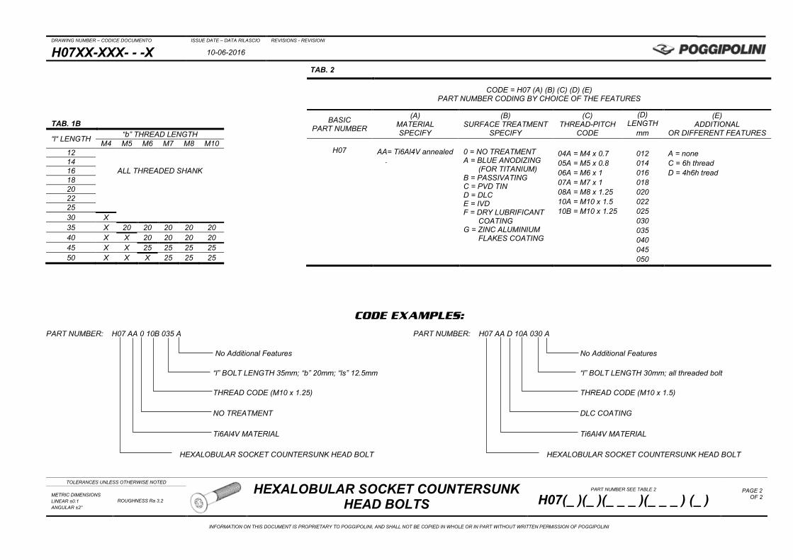
H07XX-XXX- - -X 10-06-2016
TOLERANCES UNLESS OTHERWISE NOTED
HEXALOBULAR SOCKET COUNTERSUNK HEAD BOLTS
PART NUMBER SEE TABLE 2
H07(_ )(_ )(_ _ _ )(_ _ _ ) (_ ) PAGE 1
OF 2
METRIC DIMENSIONS LINEAR ±0.1 ANGULAR ±2°
ROUGHNESS Ra 3.2
INFORMATION ON THIS DOCUMENT IS PROPRIETARY TO POGGIPOLINI, AND SHALL NOT BE COPIED IN WHOLE OR IN PART WITHOUT WRITTEN PERMISSION OF POGGIPOLINI
TYPE BOLT CODE THREAD SIZE b β Øda Øds Ødk Ødn ls lt k r s t w FIRST PART NR. EXT. PITCH SEE TAB 1B ±5° MAX +0 -0.1 +0 -0.4 MAX MIN ± MAX MIN ±0.1 NR. H. SOCKET MIN MIN
H07 M4 0.7 150° 4.7 4 8 4.2
ls =
leng
ht –
b –
2pi
tch 0.3 2.4 1.9 0.3 20 1.4 0.4
H07 M5 0.8 20 150° 5.7 5 10 4.7 0.3 3.1 2.4 0.4 25 1.8 0.6 H07 M6 1 20 - 25 150° 6.8 6 12 5.9 0.5 3.7 2.9 0.5 30 2.2 0.7 H07 M7 1 20 - 25 120° 7.8 7 14 7.0 0.5 4.2 3.4 0.6 40 2.5 0.9 H07 M8 1.25 20 - 25 120° 9.2 8 16 8.3 0.5 5 3.9 0.7 45 2.8 1.1 H07 M10 1.5 - 1.25 20 - 25 120° 11.2 10 20 9.5 0.5 6.2 4.8 0.8 50 3.2 1.6
TAB. 1
DRAWING NUMBER – CODICE DOCUMENTO ISSUE DATE – DATA RILASCIO REVISIONS - REVISIONI
H07XX-XXX- - -X 10-06-2016
TOLERANCES UNLESS OTHERWISE NOTED
HEXALOBULAR SOCKET COUNTERSUNK HEAD BOLTS
PART NUMBER SEE TABLE 2
H07(_ )(_ )(_ _ _ )(_ _ _ ) (_ ) PAGE 2
OF 2
METRIC DIMENSIONS LINEAR ±0.1 ANGULAR ±2°
ROUGHNESS Ra 3.2
INFORMATION ON THIS DOCUMENT IS PROPRIETARY TO POGGIPOLINI, AND SHALL NOT BE COPIED IN WHOLE OR IN PART WITHOUT WRITTEN PERMISSION OF POGGIPOLINI
CODE EXAMPLES:
PART NUMBER: H07 AA 0 10B 035 A PART NUMBER: H07 AA D 10A 030 A No Additional Features No Additional Features “l” BOLT LENGTH 35mm; “b” 20mm; “ls” 12.5mm “l” BOLT LENGTH 30mm; all threaded bolt THREAD CODE (M10 x 1.25) THREAD CODE (M10 x 1.5) NO TREATMENT DLC COATING Ti6Al4V MATERIAL Ti6Al4V MATERIAL HEXALOBULAR SOCKET COUNTERSUNK HEAD BOLT HEXALOBULAR SOCKET COUNTERSUNK HEAD BOLT
TAB. 2
CODE = H07 (A) (B) (C) (D) (E) PART NUMBER CODING BY CHOICE OF THE FEATURES
BASIC PART NUMBER
(A) MATERIAL SPECIFY
(B) SURFACE TREATMENT
SPECIFY
(C) THREAD-PITCH
CODE
(D) LENGTH
mm
(E) ADDITIONAL
OR DIFFERENT FEATURES
H07 AA= Ti6Al4V annealed
.
0 = NO TREATMENT A = BLUE ANODIZING
(FOR TITANIUM) B = PASSIVATING C = PVD TIN D = DLC E = IVD F = DRY LUBRIFICANT
COATING G = ZINC ALUMINIUM
FLAKES COATING
04A = M4 x 0.7 05A = M5 x 0.8 06A = M6 x 1 07A = M7 x 1 08A = M8 x 1.25 10A = M10 x 1.5 10B = M10 x 1.25
012 014 016 018 020 022 025 030 035 040 045 050
A = none C = 6h thread D = 4h6h tread
TAB. 1B
“l“ LENGTH “b” THREAD LENGTH M4 M5 M6 M7 M8 M10
12 14 16 ALL THREADED SHANK 18 20 22 25 30 X 35 X 20 20 20 20 20 40 X X 20 20 20 20 45 X X 25 25 25 25 50 X X X 25 25 25
DRAWING NUMBER – CODICE DOCUMENTO ISSUE DATE – DATA RILASCIO REVISIONS - REVISIONI
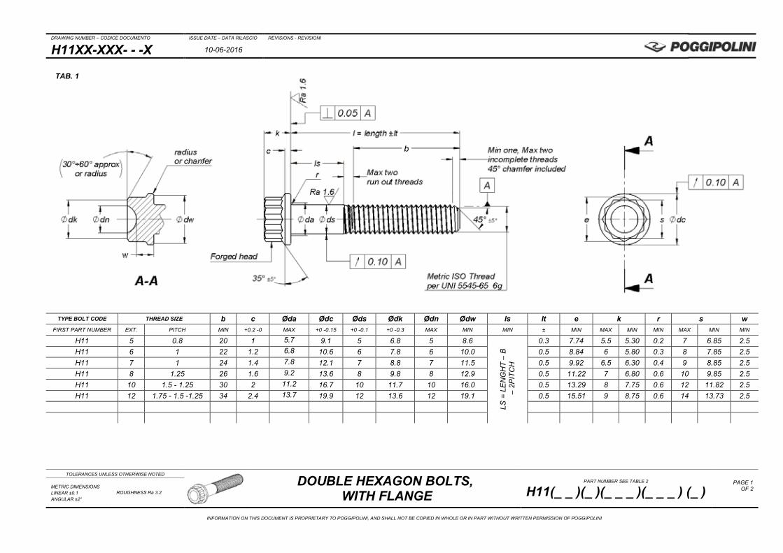
H11XX-XXX- - -X 10-06-2016
TOLERANCES UNLESS OTHERWISE NOTED
DOUBLE HEXAGON BOLTS, WITH FLANGE
PART NUMBER SEE TABLE 2
H11(_ _ )(_ )(_ _ _ )(_ _ _ ) (_ ) PAGE 1
OF 2
METRIC DIMENSIONS LINEAR ±0.1 ANGULAR ±2°
ROUGHNESS Ra 3.2
INFORMATION ON THIS DOCUMENT IS PROPRIETARY TO POGGIPOLINI, AND SHALL NOT BE COPIED IN WHOLE OR IN PART WITHOUT WRITTEN PERMISSION OF POGGIPOLINI
TYPE BOLT CODE THREAD SIZE b c Øda Ødc Øds Ødk Ødn Ødw ls lt e k r s w FIRST PART NUMBER EXT. PITCH MIN +0.2 -0 MAX +0 -0.15 +0 -0.1 +0 -0.3 MAX MIN MIN ± MIN MAX MIN MIN MAX MIN MIN
H11 5 0.8 20 1 5.7 9.1 5 6.8 5 8.6
LS =
LE
NG
HT
– B
– 2
PITC
H
0.3 7.74 5.5 5.30 0.2 7 6.85 2.5 H11 6 1 22 1.2 6.8 10.6 6 7.8 6 10.0 0.5 8.84 6 5.80 0.3 8 7.85 2.5 H11 7 1 24 1.4 7.8 12.1 7 8.8 7 11.5 0.5 9.92 6.5 6.30 0.4 9 8.85 2.5 H11 8 1.25 26 1.6 9.2 13.6 8 9.8 8 12.9 0.5 11.22 7 6.80 0.6 10 9.85 2.5 H11 10 1.5 - 1.25 30 2 11.2 16.7 10 11.7 10 16.0 0.5 13.29 8 7.75 0.6 12 11.82 2.5 H11 12 1.75 - 1.5 -1.25 34 2.4 13.7 19.9 12 13.6 12 19.1 0.5 15.51 9 8.75 0.6 14 13.73 2.5
TAB. 1

DRAWING NUMBER – CODICE DOCUMENTO ISSUE DATE – DATA RILASCIO REVISIONS - REVISIONI
H11XX-XXX- - -X 10-06-2016
TOLERANCES UNLESS OTHERWISE NOTED
DOUBLE HEXAGON BOLTS, WITH FLANGE
PART NUMBER SEE TABLE 2
H11(_ _ )(_ )(_ _ _ )(_ _ _ ) (_ ) PAGE 2
OF 2
METRIC DIMENSIONS LINEAR ±0.1 ANGULAR ±2°
ROUGHNESS Ra 3.2
INFORMATION ON THIS DOCUMENT IS PROPRIETARY TO POGGIPOLINI, AND SHALL NOT BE COPIED IN WHOLE OR IN PART WITHOUT WRITTEN PERMISSION OF POGGIPOLINI
CODE EXAMPLES:
PART NUMBER: H11 AA 0 10B 035 A PART NUMBER: H11 IA 0 06A 020 A No Additional Features No Additional Features “l” BOLT LENGTH 35mm; “b” 30mm; “ls” 2.5mm “l” BOLT LENGTH 20mm; all threaded bolt THREAD CODE (M10 x 1.25) THREAD CODE (M6 x 1) NO TREATMENT NO TREATMENT Ti6Al4V MATERIAL INCONEL 718 DOUBLE HEXAGON HEAD BOLTS, WITH FLANGE DOUBLE HEXAGON HEAD BOLTS, WITH FLANGE
TAB. 2
CODE = H11 (A) (B) (C) (D) (E) PART NUMBER CODING BY CHOICE OF THE FEATURES
BASIC PART NUMBER
(A) MATERIAL SPECIFY
(B) SURFACE TREATMENT
SPECIFY
(C) THREAD-PITCH
CODE
(D) LENGTH
mm
(E) ADDITIONAL
OR DIFFERENT FEATURES
H11 AA= TI6AL4V ANN. BC= AL 7068 T6511 DA=13-8 PH 1517MPa min 10%A min FA= 17-4 PH 1310MPamin 10%A min GA= AISI 4340 1200MPa min 16%A min HA= MLX 17 1655MPa min 10%A min IA= INCONEL 718 1480MPa min 10%A min JA=AERMET 100 1999MPa 8%A min MA= 30NCD16 1350MPa min 14%A min
0 = NO TREATMENT A = ANODIZING
(BLUE FOR TITANIUM) B = PASSIVATING C = PVD TIN D = DLC E = IVD F = DRY LUBRIFICANT
COATING G = ZINC ALUMINIUM
FLAKES COATING
04A = M4 x 0.7 05A = M5 x 0.8 06A = M6 x 1 07A = M7 x 1 08A = M8 x 1.25 10A = M10 x 1.5 10B = M10 x 1.25 12A = M12 x 1.75 12B = M12 x 1.5 12C = M12 x 1.25
010 015 020 025 030 035 040 045 050 ÷
140
A = none C = 6h thread D = 4h6h tread
TAB. 1B “l“ LENGTH 5mm step
“b” THREAD LENGTH M5 M6 M7 M8 M10 M12
10 15 ALL THREADED SHANK 20 25 20 22 24 30 20 22 24 26 35 20 22 24 26 30 34 40 20 22 24 26 30 34 45 20 22 24 26 30 34 50 20 22 24 26 30 34 55 X X 24 26 30 34 60 X X 24 26 30 34 ÷ ÷ ÷ ÷ ÷ ÷ ÷
100 X X 24 26 30 34 ÷ ÷ ÷ ÷ ÷ ÷ ÷
140 X X X 26 30 34
DRAWING NUMBER – CODICE DOCUMENTO ISSUE DATE – DATA RILASCIO REVISIONS - REVISIONI
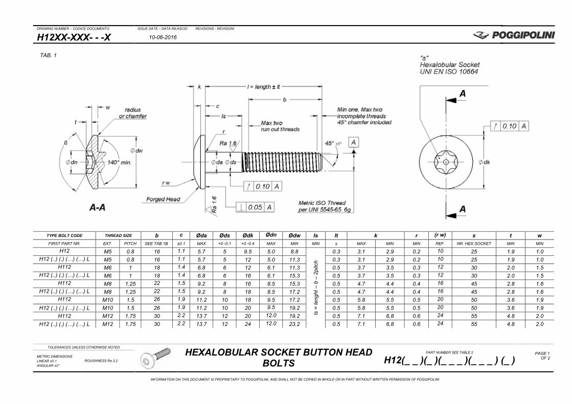
H12XX-XXX- - -X 10-06-2016
TOLERANCES UNLESS OTHERWISE NOTED
HEXALOBULAR SOCKET BUTTON HEAD BOLTS
PART NUMBER SEE TABLE 2
H12(_ _ )(_ )(_ _ _ )(_ _ _ ) (_ ) PAGE 1
OF 2
METRIC DIMENSIONS LINEAR ±0.1 ANGULAR ±2°
ROUGHNESS Ra 3.2
INFORMATION ON THIS DOCUMENT IS PROPRIETARY TO POGGIPOLINI, AND SHALL NOT BE COPIED IN WHOLE OR IN PART WITHOUT WRITTEN PERMISSION OF POGGIPOLINI
TYPE BOLT CODE THREAD SIZE b c Øda Øds Ødk Ødn Ødw ls lt k r (r w) s t w FIRST PART NR. EXT. PITCH SEE TAB 1B ±0.1 MAX +0 -0.1 +0 -0.4 MAX MIN MIN ± MAX MIN MIN REF. NR. HEX.SOCKET MIN MIN
H12 M5 0.8 16 1.1 5.7 5 9.5 5.0 8.8
ls =
leng
ht –
b –
2pi
tch
0.3 3.1 2.9 0.2 10 25 1.9 1.0 H12 (..) (.) (…) (…) L M5 0.8 16 1.1 5.7 5 12 5.0 11.3 0.3 3.1 2.9 0.2 10 25 1.9 1.0
H112 M6 1 18 1.4 6.8 6 12 6.1 11.3 0.5 3.7 3.5 0.3 12 30 2.0 1.5 H12 (..) (.) (…) (…) L M6 1 18 1.4 6.8 6 16 6.1 15.3 0.5 3.7 3.5 0.3 12 30 2.0 1.5
H112 M8 1.25 22 1.5 9.2 8 16 8.5 15.3 0.5 4.7 4.4 0.4 16 45 2.8 1.6 H12 (..) (.) (…) (…) L M8 1.25 22 1.5 9.2 8 18 8.5 17.2 0.5 4.7 4.4 0.4 16 45 2.8 1.6
H112 M10 1.5 26 1.9 11.2 10 18 9.5 17.2 0.5 5.8 5.5 0.5 20 50 3.6 1.9 H12 (..) (.) (…) (…) L M10 1.5 26 1.9 11.2 10 20 9.5 19.2 0.5 5.8 5.5 0.5 20 50 3.6 1.9
H112 M12 1.75 30 2.2 13.7 12 20 12.0 19.2 0.5 7.1 6.8 0.6 24 55 4.8 2.0 H12 (..) (.) (…) (…) L M12 1.75 30 2.2 13.7 12 24 12.0 23.2 0.5 7.1 6.8 0.6 24 55 4.8 2.0
TAB. 1

DRAWING NUMBER – CODICE DOCUMENTO ISSUE DATE – DATA RILASCIO REVISIONS - REVISIONI
H12XX-XXX- - -X 10-06-2016
TOLERANCES UNLESS OTHERWISE NOTED
HEXALOBULAR SOCKET BUTTON HEAD BOLTS
PART NUMBER SEE TABLE 2
H12(_ _ )(_ )(_ _ _ )(_ _ _ ) (_ ) PAGE 2
OF 2
METRIC DIMENSIONS LINEAR ±0.1 ANGULAR ±2°
ROUGHNESS Ra 3.2
INFORMATION ON THIS DOCUMENT IS PROPRIETARY TO POGGIPOLINI, AND SHALL NOT BE COPIED IN WHOLE OR IN PART WITHOUT WRITTEN PERMISSION OF POGGIPOLINI
CODE EXAMPLES:
PART NUMBER: H12 AA 0 06A 035 A PART NUMBER: H12 AA A 10A 030 L No Additional Features with “different feature”: INCREASED HEAD “l” SCREW LENGTH 35mm; “b” 18mm; “ls” 15mm “l” 30mm SCREW LENGTH; ALL THREADED SHANK THREAD CODE (M6 x 1) THREAD CODE (M10 x 1.5) NOTREATMENT BLUE ANODIZING Ti6Al4V MATERIAL Ti6Al4V MATERIAL HEXALOBULAR SOCKET BUTTON HEAD BOLTS HEXALOBULAR SOCKET BUTTON HEAD BOLTS
TAB. 2
CODE = H12 (A) (B) (C) (D) (E) PART NUMBER CODING BY CHOICE OF THE FEATURES
BASIC PART NUMBER
(A) MATERIAL SPECIFY
(B) SURFACE TREATMENT
SPECIFY
(C) THREAD-PITCH
CODE
(D) LENGTH
mm
(E) ADDITIONAL
OR DIFFERENT FEATURES
H12
AA= Ti6Al4V annealed
0 = NO TREATMENT A = BLUE ANODIZING
(FOR TITANIUM) B = PASSIVATING C = PVD TIN D = DLC E = IVD F = DRY LUBRIFICANT
COATING G = ZINC ALUMINIUM
FLAKES COATING
05A = M5 x 0.8 06A = M6 x 1 08A = M8 x 1.25 10A = M10 x 1.5 12A = M12 x 1.75
010 012 015 020 025 030 035 040 045 050 ÷
140
A = none L = increased Ødk head
TAB. 1B
“l“ LENGTH (5mm step)
“b” THREAD LENGTH M5 M6 M8 M10 M12
10 12 ALL THREADED SHANK 15 20 25 16 18 22
30 16 18 22 35 16 18 22 26 30 40 16 18 22 26 30 45 16 18 22 26 30 50 16 18 22 26 30 55 16 18 22 26 30 60 16 18 22 26 30 ÷ X ÷ ÷ ÷ ÷
100 X 18 22 26 30 ÷ X X ÷ ÷ ÷
140 X X 22 26 30

DRAWING NUMBER – CODICE DOCUMENTO ISSUE DATE – DATA RILASCIO REVISIONS - REVISIONI
H13XX-XXX- - -X 26-10-2015
TOLERANCES UNLESS OTHERWISE NOTED HEXAGON HEAD BOLTS WITH LARGE
FLANGE PART NUMBER SEE TABLE 2
H13(_ _ )(_ )(_ _ _ )(_ _ _ ) (_ ) PAGE 1
OF 2
METRIC DIMENSIONS LINEAR ±0.1 ANGULAR ±2°
ROUGHNESS Ra 3.2
INFORMATION ON THIS DOCUMENT IS PROPRIETARY TO POGGIPOLINI, AND SHALL NOT BE COPIED IN WHOLE OR IN PART WITHOUT WRITTEN PERMISSION OF POGGIPOLINI
TYPE BOLT CODE THREAD SIZE b ls lt c Øda Ødc Øds Ødk Ødw Ødn e k r s r n w FIRST PART NR. EXT. PITCH SEE TAB 1B MIN ± +0.2 -0 MAX +0 -0.15 +0 -0.1 +0 -0.15 MIN MAX MIN MAX MIN MIN MAX MIN REF. MIN
H13 M4 0.7 20 - 25
ls =
leng
ht –
b –
2pi
tch 0.3 1.0 4.7 10 4 6 9.5 4.4 6.51 4.5 4.3 0.2 6 5.85 2.7 2.3
H13 M5 0.8 20 - 25 0.3 1.0 5.7 11 5 7 10.5 5.0 7.59 5.0 4.8 0.2 7 6.85 3.0 2.5 H13 M6 1 22 - 25 0.5 1.3 6.8 13 6 8 12.4 5.6 8.71 5.5 5.3 0.3 8 7.85 3.3 2.7 H13 M8 1.25 22 - 25 0.5 1.3 9.2 16 8 10 15.4 7.0 10.95 6.5 6.3 0.4 10 9.85 4.0 3.0 H13 M10 1.5 - 1.25 26 - 30 0.5 1.5 11.2 20 10 12 19.3 9.0 13.29 8.0 7.7 0.4 12 11.82 5.0 3.5 H13 M12 1.75 - 1.5 - 1.25 26 - 30 0.5 1.8 13.7 24 12 14 13.2 10.5 15.38 10 9.7 0.6 14 13.73 6.0 4.5 H13 M14 2 - 1.75 - 1.5 - 1.25 26 - 30 0.5 2.1 15.7 28 14 17 27.2 13.5 18.75 12 11.7 0.8 17 16.73 7.5 5.0 H13 M16 2 – 1.75 - 1.5 26 - 30 0.5 2.4 17.7 30 16 20 29.2 16.0 22.06 14 13.6 0.8 20 19.67 9 5.5
TAB. 1

DRAWING NUMBER – CODICE DOCUMENTO ISSUE DATE – DATA RILASCIO REVISIONS - REVISIONI
H13XX-XXX- - -X 26-10-2015
TOLERANCES UNLESS OTHERWISE NOTED HEXAGON HEAD BOLTS WITH LARGE
FLANGE PART NUMBER SEE TABLE 2
H13(_ _ )(_ )(_ _ _ )(_ _ _ ) (_ ) PAGE 2
OF 2
METRIC DIMENSIONS LINEAR ±0.1 ANGULAR ±2°
ROUGHNESS Ra 3.2
INFORMATION ON THIS DOCUMENT IS PROPRIETARY TO POGGIPOLINI, AND SHALL NOT BE COPIED IN WHOLE OR IN PART WITHOUT WRITTEN PERMISSION OF POGGIPOLINI
CODE EXAMPLES:
PART NUMBER: H13 AA 0 10B 035 A PART NUMBER: H13 AA D 12A 030 A None Additional Features None Additional Features “l” BOLT LENGTH 35mm; “b” 30mm; “ls” 2.5mm “l” BOLT LENGTH 30mm; all threaded bolt THREAD CODE (M10 x 1.25) THREAD CODE (M12 x 1.75) WITHOUT TREATMENT DLC COATING Ti6Al4V MATERIAL Ti6Al4V MATERIAL HEXAGON HEAD BOLT WITH LARGE FLANGE HEXAGON HEAD BOLT WITH LARGE FLANGE
TAB. 2 CODE = H13 (A) (B) (C) (D) (E)
PART NUMBER CODING BY CHOICE OF THE FEATURES
BASIC PART
NUMBER
(A) MATERIAL SPECIFY
(B) SURFACE TREATMENT
SPECIFY
(C) THREAD-PITCH
CODE
(D) LENGTH
mm
(E) ADDITIONAL OR
DIFFERENT FEATURES
H13
AA= Ti6Al4V annealed BA= 7075 T6-T651 BC= AL 7068 T6511 GA= AISI 4340 1200MPa min 16%A min HA= MLX 17 1655MPa min 10%A min JA=AERMET 100 1999MPa 8%A min KA= MP35N 1793MPa min 8%A min LA= MARAGING 300 2035MPa min 12%A min MA= 30NCD16 1350MPa min 14%A min NA= CRES A286 Rm1150÷1200MPa
0 = NO TREATMENT A = ANODIZING
(BLUE FOR TITANIUM) B = PASSIVATING C = PVD TIN D = DLC E = IVD F = DRY LUBRIFICANT
COATING G = ZINC ALUMINIUM
FLAKES COATING
04A = M4 x 0.7 05A = M5 x 0.8 06A = M6 x 1 07A = M7 x 1 08A = M8 x 1.25 08B = M8 x 1 10A = M10 x 1.5 10B = M10 x 1.25 12A = M12 x 1.75 12B = M12 x 1.5 12C = M12 x 1.25 14A = M14 x 2 14B = M14 x 1.75 14C = M 14 x 1.5 14D = M 14 x 1.25 16A = M 16 x 2 16B = M16 x 1.75 16C = M16 x 1.5
010 015 020 025 030 035 040 045 050 ÷
140
A = none C = 6h thread D = 4h6h tread
TAB. 1B “l“ LENGTH 5mm step
“b” THREAD LENGTH M4 M5 M6 M8 M10 M12 M14 M16
10 ALL THREADED SHANK 15
20 25 20 20 22 22 30 20 20 22 25 26 26 26 26 35 20 20 25 25 30 30 30 30 40 25 25 25 25 30 30 30 30 45 X 25 25 25 30 30 30 30 50 X 25 25 25 30 30 30 30 55 X X 25 25 30 30 30 30 60 X X 25 25 30 30 30 30 ÷ ÷ ÷ ÷ ÷ ÷ ÷ ÷ ÷
140 X X X 25 30 30 30 30
DRAWING NUMBER – CODICE DOCUMENTO ISSUE DATE – DATA RILASCIO REVISIONS - REVISIONI
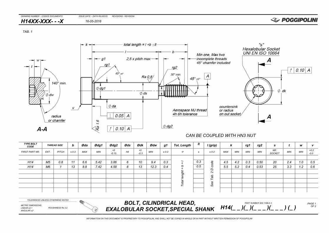
H14XX-XXX- - -X 16-05-2016
TOLERANCES UNLESS OTHERWISE NOTED
BOLT, CILINDRICAL HEAD, EXALOBULAR SOCKET,SPECIAL SHANK
PART NUMBER SEE TABLE 2
H14(_ _ )(_ )(_ _ _ )(_ _ _ ) (_ ) PAGE 1
OF 2
METRIC DIMENSIONS LINEAR ±0.1 ANGULAR ±2°
ROUGHNESS Ra 3.2
INFORMATION ON THIS DOCUMENT IS PROPRIETARY TO POGGIPOLINI, AND SHALL NOT BE COPIED IN WHOLE OR IN PART WITHOUT WRITTEN PERMISSION OF POGGIPOLINI
TYPE BOLT CODE THREAD SIZE b Øda Ødg1 Ødg2 Øds Ødk Ødw g1 Tot. Length lt l (grip) k rg1 rg2 s t w v
FIRST PART NR. EXT. PITCH ± 0.3 MAX MIN +0 -0.15 h8 +0
-0.3 MIN ± 0.2 ± ± 0.2 MAX MIN MIN MIN NR. SOCKET MIN MIN +0.2
-0.0
Tota
l len
ght =
b +
l
See
Tab
. 2 D
cod
e
H14 M5 0.8 11 6.6 5.42 3.86 6 10 9.4 0.3 0.3 4.5 4.2 0.3 0.50 20 2.4 1.0 0.5 H14 M6 1 13 8.8 7.42 4.58 8 13 12.3 0.4 0.5 5.5 5.2 0.4 0.53 25 3.3 1.2 0.6
TAB. 1
CAN BE COUPLED WITH HN3 NUT
DRAWING NUMBER – CODICE DOCUMENTO ISSUE DATE – DATA RILASCIO REVISIONS - REVISIONI
H14XX-XXX- - -X 16-05-2016
TOLERANCES UNLESS OTHERWISE NOTED
BOLT, CILINDRICAL HEAD, EXALOBULAR SOCKET,SPECIAL SHANK
PART NUMBER SEE TABLE 2
H14(_ _ )(_ )(_ _ _ )(_ _ _ ) (_ ) PAGE 2
OF 2
METRIC DIMENSIONS LINEAR ±0.1 ANGULAR ±2°
ROUGHNESS Ra 3.2
INFORMATION ON THIS DOCUMENT IS PROPRIETARY TO POGGIPOLINI, AND SHALL NOT BE COPIED IN WHOLE OR IN PART WITHOUT WRITTEN PERMISSION OF POGGIPOLINI
CODE EXAMPLES:
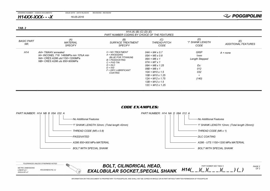
PART NUMBER: H14 NB B 05A 032 A PART NUMBER: H14 NA D 06A 012 A
No Additional Features No Additional Features
“l” SHANK LENGTH 32mm; (Total length 42mm) “l” SHANK LENGTH 12mm; (Total length 25mm))
THREAD CODE (M5 x 0.8) THREAD CODE (M6 x 1)
PASSIVATED DLC COATING
A286 850÷900 MPa MATERIAL A286 - UTS 1150÷1200 MPa MATERIAL
BOLT WITH SPECIAL SHANK BOLT WITH SPECIAL SHANK
TAB. 2 H14 (A) (B) (C) (D) (E)
PART NUMBER CODING BY CHOICE OF THE FEATURES
BASIC PART NR.
(A) MATERIAL SPECIFY
(B) SURFACE TREATMENT
SPECIFY
(C) THREAD-PITCH
CODE
(D) “l” SHANK LENGTH
CODE
(E) ADDITIONAL FEATURES
H14
AA= Ti6Al4V annealed IA= INCONEL 718 1480MPa min 10%A min NA= CRES A286 uts1150÷1200MPa NB= CRES A286 uts 850÷900MPa
0 = NO TREATMENT A = ANODIZING
(BLUE FOR TITANIUM) B = PASSIVATING C = PVD TIN D = DLC E = IVD F = DRY LUBRIFICANT
COATING
04A = M4 x 0.7 05A = M5 x 0.8 06A = M6 x 1 07A = M7 x 1 08A = M8 x 1.25 08B = M8 x 1 10A = M10 x 1.5 10B = M10 x 1.25 12A = M12 x 1.75 12B = M12 x 1.5 12C = M12 x 1.25
GRIP 1mm
Length Stepped
Ex: 012 032 ÷
(140)
A = none
DRAWING NUMBER – CODICE DOCUMENTO ISSUE DATE – DATA RILASCIO REVISIONS - REVISIONI
H15XX-XXX- - -X 24-05-2016
TOLERANCES UNLESS OTHERWISE NOTED
SCREW, FLAT 100° FLUSH HEAD, CLOSE TOLERANCE, SHORT THREAD,
OFFSET CRUCIFORM RECESS PART NUMBER SEE TABLE 2
H15(_ _ )(_ )(_ _ _ )(_ _ _ )(_ ) PAGE 1
OF 3
METRIC DIMENSIONS LINEAR ±0.1 ANGULAR ±2°
ROUGHNESS Ra 3.2
INFORMATION ON THIS DOCUMENT IS PROPRIETARY TO POGGIPOLINI, AND SHALL NOT BE COPIED IN WHOLE OR IN PART WITHOUT WRITTEN PERMISSION OF POGGIPOLINI
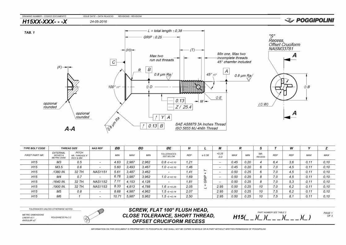
TYPE BOLT CODE THREAD SIZE NAS REF ØB ØD ØE H L M R S T W Y Z
FIRST PART NR. EXTERNAL
INCHES & METRIC DIAM.
PITCH NR. THREADS X INCH & MM
MIN MAX MIN TOLLERANCES. SEE BELOW REF ± 0.38 +0.25
-0.0 MAX MIN NR. RECESS
REF REF MAX MAX
H15 M3 0.5 - 4.63 2,987 2,962 0.8 -0 +0.10 1,21
L =
GR
IP +
T
- 0.45 0.20 4 6,4 3,6 0,11 0,10 H15 M3.5 0.6 - 5.60 3,493 3,467 1.0 -0 +0.10 1,46 - 0.45 0.20 6 7,0 4,5 0,11 0,10 H15 .1380 IN. 32 TH. NAS1151 5.61 3,487 3,462 - 1,41 - 0.50 0.25 6 7,0 4,5 0,11 0,10 H15 M4 0.7 - 6.78 3,987 3,962 1.0 -0 +0.10 1,69 - 0.50 0.25 8 7,0 4,5 0,11 0,10 H15 .1640 IN. 32 TH. NAS1152 7.11 4,153 4,128 - 1,81 - 0.50 0.25 8 7,0 5,3 0,11 0,10 H15 .1900 IN. 32 TH. NAS1153 8.33 4,813 4,788 1.6 -0 +0.25 2,05 2.95 0.50 0.25 10 7,0 6,2 0,11 0,10 H15 M5 0.8 - 8.68 4,987 4,962 1.5 -0 +0.14 2,07 2.95 0.50 0.25 10 7,5 6,2 0,11 0,10 H15 M6 1 - 10.71 5,987 5,962 1.5 -0 +0.14 2,50 2.95 0.50 0.25 10 7,5 8,1 0,11 0,10
TAB. 1

DRAWING NUMBER – CODICE DOCUMENTO ISSUE DATE – DATA RILASCIO REVISIONS - REVISIONI
H15XX-XXX- - -X 24-05-2016
TOLERANCES UNLESS OTHERWISE NOTED
SCREW, FLAT 100° FLUSH HEAD, CLOSE TOLERANCE, SHORT THREAD,
OFFSET CRUCIFORM RECESS PART NUMBER SEE TABLE 2
H15(_ _ )(_ )(_ _ _ )(_ _ _ )(_ ) PAGE 2
OF 3
METRIC DIMENSIONS LINEAR ±0.1 ANGULAR ±2°
ROUGHNESS Ra 3.2
INFORMATION ON THIS DOCUMENT IS PROPRIETARY TO POGGIPOLINI, AND SHALL NOT BE COPIED IN WHOLE OR IN PART WITHOUT WRITTEN PERMISSION OF POGGIPOLINI
TYPE BOLT CODE THREAD SIZE NAS REF ØB ØD ØE H L M R S T W Y Z
FIRST PART NR. EXTERNAL
INCHES & METRIC DIAM.
PITCH NR. THREADS X INCH & MM
MIN MAX MIN TOLLERANCES. SEE BELOW REF ± 0.38 +0.25
-0.0 MAX MIN NR. RECESS
REF REF MAX MAX
H15 .2500 IN. 28 TH. NAS1154 11.40 6,337 6,312 1.9 -0 +0.25 2,70
L =
GR
IP +
T
2.95 0.50 0.25 1/4 8,0 8,1 0,11 0,08 H15 M7 1 - 12.70 6,987 6,962 1.5 -0 +0.14 2,91 2.95 0.64 0.30 1/4 8,0 8,1 0,11 0,08 H15 .3125 IN. 24 TH. NAS1155 14.66 7,925 7,899 1.9 -0 +0.25 3,39 3.00 0.64 0.30 5/16 9,5 8,9 0,15 0,08 H15 M8 1.25 - 14.78 7,987 7,962 2.0 -0 +0.25 3,37 3.00 0.76 0.40 5/16 9,5 8,9 0,15 0,08 H15 .3750 IN. 24 TH. NAS1156 17.88 9,512 9,487 2.7 -0 +0.25 4,08 3.05 0.76 0.40 3/8 9,9 10,7 0,15 0,06 H15 M10 1.5 - 18.83 9,987 9,962 2.0 -0 +0.25 4,23 3.10 0.76 0.40 3/8 10,0 10,7 0,15 0,06 H15 .4375 IN. 20 TH. NAS1157 21.13 11,100 11,074 2.7 -0 +0.25 4,78 3.10 0.76 0.40 7/16 11,5 12,5 0,15 0,06 H15 M12 1.5 - 22.95 11,987 11,962 3.0 -0 +0.25 5,12 3.10 0.76 0.40 1/2 11,5 14,3 0,15 0,05 H15 .5000 IN 20 TH. NAS1158 24.36 12,687 12,662 2.7 -0 +0.25 5,47 3.15 0.76 0.40 1/2 11,5 14,3 0,15 0,05
DRAWING NUMBER – CODICE DOCUMENTO ISSUE DATE – DATA RILASCIO REVISIONS - REVISIONI
H15XX-XXX- - -X 24-05-2016
TOLERANCES UNLESS OTHERWISE NOTED
SCREW, FLAT 100° FLUSH HEAD, CLOSE TOLERANCE, SHORT THREAD,
OFFSET CRUCIFORM RECESS PART NUMBER SEE TABLE 2
H15(_ _ )(_ )(_ _ _ )(_ _ _ )(_ ) PAGE 3
OF 3
METRIC DIMENSIONS LINEAR ±0.1 ANGULAR ±2°
ROUGHNESS Ra 3.2
INFORMATION ON THIS DOCUMENT IS PROPRIETARY TO POGGIPOLINI, AND SHALL NOT BE COPIED IN WHOLE OR IN PART WITHOUT WRITTEN PERMISSION OF POGGIPOLINI
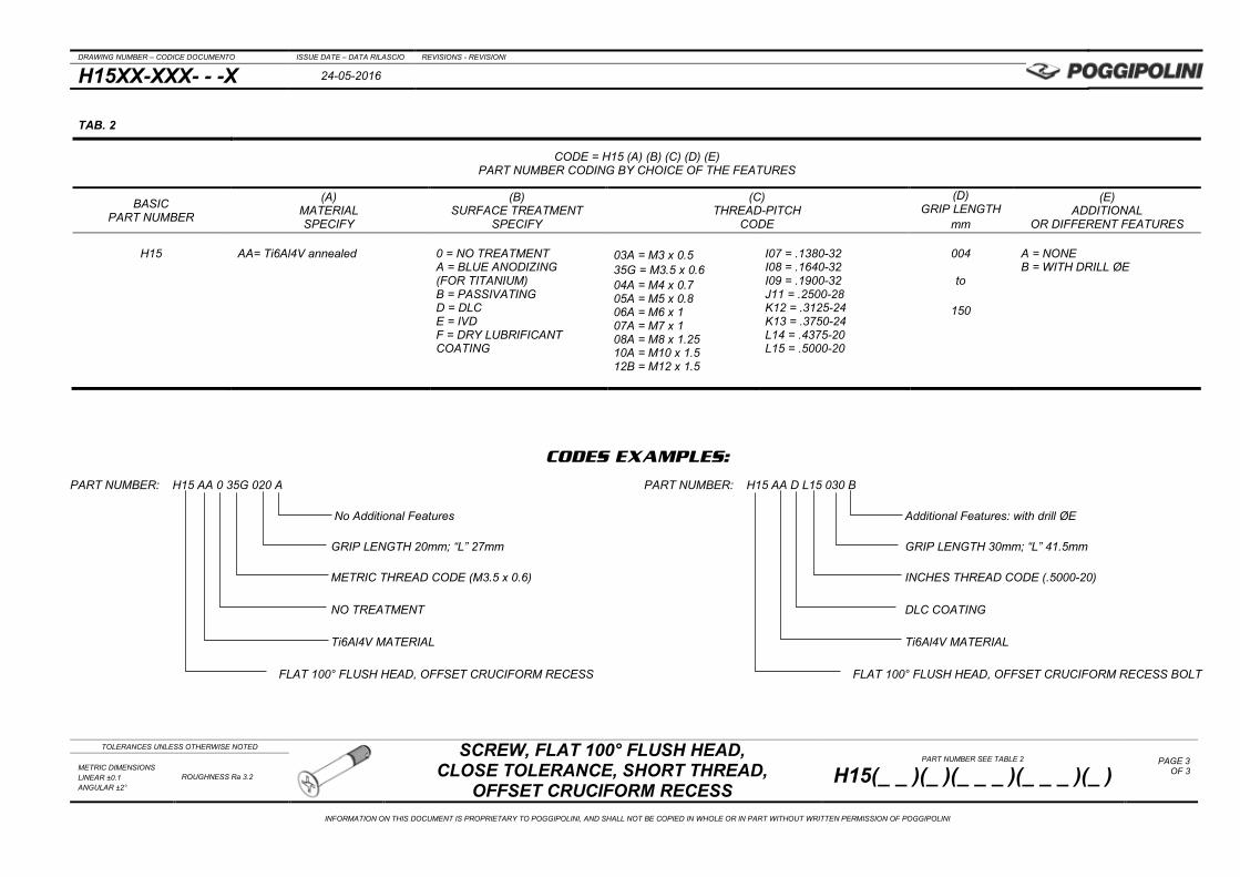
CODES EXAMPLES:
PART NUMBER: H15 AA 0 35G 020 A PART NUMBER: H15 AA D L15 030 B No Additional Features Additional Features: with drill ØE GRIP LENGTH 20mm; “L” 27mm GRIP LENGTH 30mm; “L” 41.5mm METRIC THREAD CODE (M3.5 x 0.6) INCHES THREAD CODE (.5000-20) NO TREATMENT DLC COATING Ti6Al4V MATERIAL Ti6Al4V MATERIAL FLAT 100° FLUSH HEAD, OFFSET CRUCIFORM RECESS FLAT 100° FLUSH HEAD, OFFSET CRUCIFORM RECESS BOLT
TAB. 2
CODE = H15 (A) (B) (C) (D) (E) PART NUMBER CODING BY CHOICE OF THE FEATURES
BASIC PART NUMBER
(A) MATERIAL SPECIFY
(B) SURFACE TREATMENT
SPECIFY
(C) THREAD-PITCH
CODE
(D) GRIP LENGTH
mm
(E) ADDITIONAL
OR DIFFERENT FEATURES
H15 AA= Ti6Al4V annealed
0 = NO TREATMENT A = BLUE ANODIZING (FOR TITANIUM) B = PASSIVATING D = DLC E = IVD F = DRY LUBRIFICANT COATING
03A = M3 x 0.5 35G = M3.5 x 0.6 04A = M4 x 0.7 05A = M5 x 0.8 06A = M6 x 1 07A = M7 x 1 08A = M8 x 1.25 10A = M10 x 1.5 12B = M12 x 1.5
I07 = .1380-32 I08 = .1640-32 I09 = .1900-32 J11 = .2500-28 K12 = .3125-24 K13 = .3750-24 L14 = .4375-20 L15 = .5000-20
004
to
150
A = NONE B = WITH DRILL ØE
DRAWING NUMBER – CODICE DOCUMENTO ISSUE DATE – DATA RILASCIO REVISIONS - REVISIONI
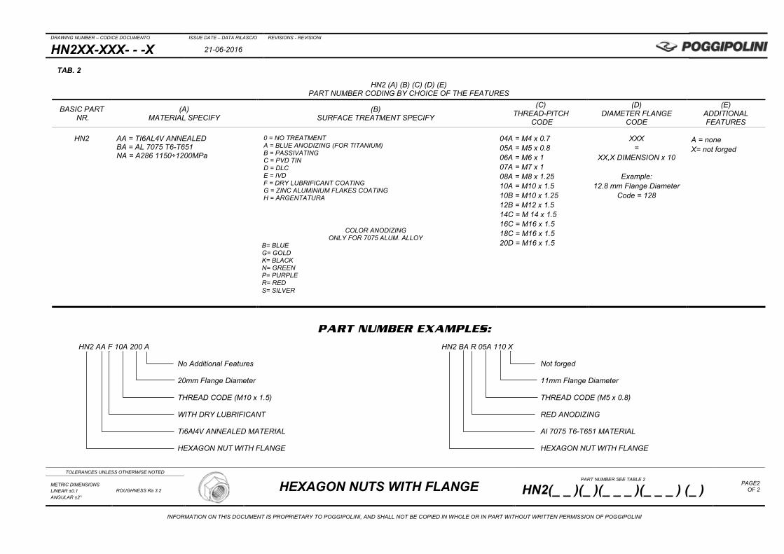
HN2XX-XXX- - -X 21-06-2016
TOLERANCES UNLESS OTHERWISE NOTED
HEXAGON NUTS WITH FLANGE PART NUMBER SEE TABLE 2
HN2(_ _ )(_ )(_ _ _ )(_ _ _ ) (_ ) PAGE1
OF 2 METRIC DIMENSIONS LINEAR ±0.1 ANGULAR ±2°
ROUGHNESS Ra 3.2
INFORMATION ON THIS DOCUMENT IS PROPRIETARY TO POGGIPOLINI, AND SHALL NOT BE COPIED IN WHOLE OR IN PART WITHOUT WRITTEN PERMISSION OF POGGIPOLINI
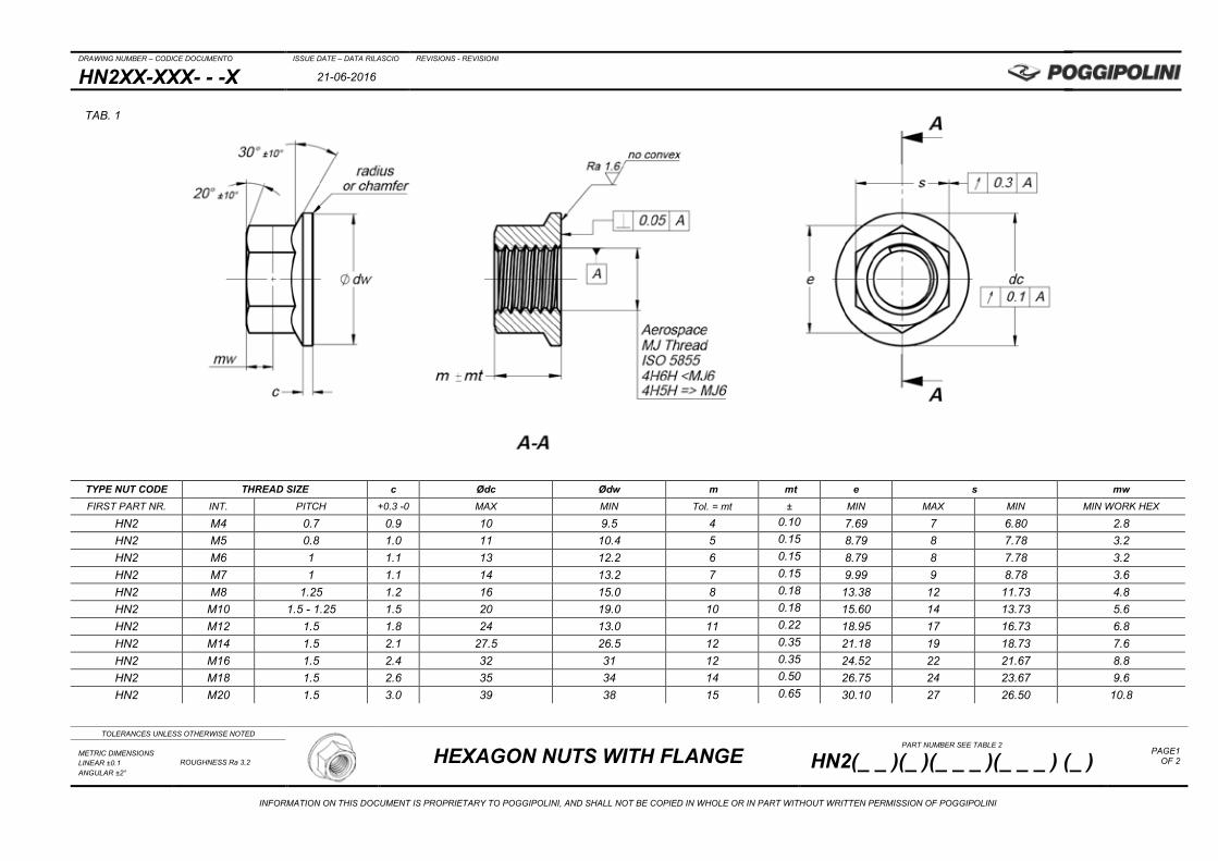
TYPE NUT CODE THREAD SIZE c Ødc Ødw m mt e s mw FIRST PART NR. INT. PITCH +0.3 -0 MAX MIN Tol. = mt ± MIN MAX MIN MIN WORK HEX
HN2 M4 0.7 0.9 10 9.5 4 0.10 7.69 7 6.80 2.8 HN2 M5 0.8 1.0 11 10.4 5 0.15 8.79 8 7.78 3.2 HN2 M6 1 1.1 13 12.2 6 0.15 8.79 8 7.78 3.2 HN2 M7 1 1.1 14 13.2 7 0.15 9.99 9 8.78 3.6 HN2 M8 1.25 1.2 16 15.0 8 0.18 13.38 12 11.73 4.8 HN2 M10 1.5 - 1.25 1.5 20 19.0 10 0.18 15.60 14 13.73 5.6 HN2 M12 1.5 1.8 24 13.0 11 0.22 18.95 17 16.73 6.8 HN2 M14 1.5 2.1 27.5 26.5 12 0.35 21.18 19 18.73 7.6 HN2 M16 1.5 2.4 32 31 12 0.35 24.52 22 21.67 8.8 HN2 M18 1.5 2.6 35 34 14 0.50 26.75 24 23.67 9.6 HN2 M20 1.5 3.0 39 38 15 0.65 30.10 27 26.50 10.8
TAB. 1
DRAWING NUMBER – CODICE DOCUMENTO ISSUE DATE – DATA RILASCIO REVISIONS - REVISIONI
HN2XX-XXX- - -X 21-06-2016
TOLERANCES UNLESS OTHERWISE NOTED
HEXAGON NUTS WITH FLANGE PART NUMBER SEE TABLE 2
HN2(_ _ )(_ )(_ _ _ )(_ _ _ ) (_ ) PAGE2
OF 2 METRIC DIMENSIONS LINEAR ±0.1 ANGULAR ±2°
ROUGHNESS Ra 3.2
INFORMATION ON THIS DOCUMENT IS PROPRIETARY TO POGGIPOLINI, AND SHALL NOT BE COPIED IN WHOLE OR IN PART WITHOUT WRITTEN PERMISSION OF POGGIPOLINI
PART NUMBER EXAMPLES:
HN2 AA F 10A 200 A HN2 BA R 05A 110 X
No Additional Features Not forged
20mm Flange Diameter 11mm Flange Diameter
THREAD CODE (M10 x 1.5) THREAD CODE (M5 x 0.8)
WITH DRY LUBRIFICANT RED ANODIZING
Ti6Al4V ANNEALED MATERIAL Al 7075 T6-T651 MATERIAL
HEXAGON NUT WITH FLANGE HEXAGON NUT WITH FLANGE
TAB. 2
HN2 (A) (B) (C) (D) (E) PART NUMBER CODING BY CHOICE OF THE FEATURES
BASIC PART NR.
(A) MATERIAL SPECIFY
(B) SURFACE TREATMENT SPECIFY
(C) THREAD-PITCH
CODE
(D) DIAMETER FLANGE
CODE
(E) ADDITIONAL FEATURES
HN2
AA = TI6AL4V ANNEALED BA = AL 7075 T6-T651 NA = A286 1150÷1200MPa
0 = NO TREATMENT A = BLUE ANODIZING (FOR TITANIUM) B = PASSIVATING C = PVD TIN D = DLC E = IVD F = DRY LUBRIFICANT COATING G = ZINC ALUMINIUM FLAKES COATING H = ARGENTATURA
04A = M4 x 0.7 05A = M5 x 0.8 06A = M6 x 1 07A = M7 x 1 08A = M8 x 1.25 10A = M10 x 1.5 10B = M10 x 1.25 12B = M12 x 1.5 14C = M 14 x 1.5 16C = M16 x 1.5 18C = M16 x 1.5 20D = M16 x 1.5
XXX =
XX,X DIMENSION x 10
Example: 12.8 mm Flange Diameter
Code = 128
A = none X= not forged
COLOR ANODIZING
ONLY FOR 7075 ALUM. ALLOY B= BLUE G= GOLD K= BLACK N= GREEN P= PURPLE R= RED S= SILVER
DRAWING NUMBER – CODICE DOCUMENTO ISSUE DATE – DATA RILASCIO REVISIONS - REVISIONI
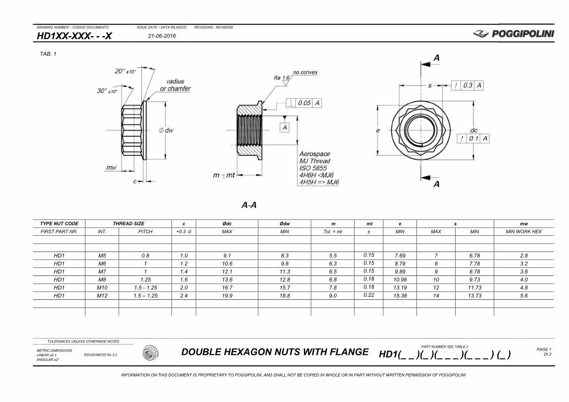
HD1XX-XXX- - -X 21-06-2016
TOLERANCES UNLESS OTHERWISE NOTED
DOUBLE HEXAGON NUTS WITH FLANGE PART NUMBER SEE TABLE 2
HD1(_ _ )(_ )(_ _ _ )(_ _ _ ) (_ ) PAGE 1
DI 2 METRIC DIMENSIONS LINEAR ±0.1 ANGULAR ±2°
ROUGHNESS Ra 3.2
INFORMATION ON THIS DOCUMENT IS PROPRIETARY TO POGGIPOLINI, AND SHALL NOT BE COPIED IN WHOLE OR IN PART WITHOUT WRITTEN PERMISSION OF POGGIPOLINI
TYPE NUT CODE THREAD SIZE c Ødc Ødw m mt e s mw FIRST PART NR. INT. PITCH +0.3 -0 MAX MIN Tol. = mt ± MIN MAX MIN MIN WORK HEX
HD1 M5 0.8 1.0 9.1 8.3 5.5 0.15 7.69 7 6.78 2.8 HD1 M6 1 1.2 10.6 9.8 6.3 0.15 8.79 8 7.78 3.2 HD1 M7 1 1.4 12.1 11.3 6.5 0.15 9.89 9 8.78 3.6 HD1 M8 1.25 1.6 13.6 12.8 6.8 0.18 10.98 10 9.73 4.0 HD1 M10 1.5 - 1.25 2.0 16.7 15.7 7.8 0.18 13.19 12 11.73 4.8 HD1 M12 1.5 – 1.25 2.4 19.9 18.8 9.0 0.22 15.38 14 13.73 5.6
TAB. 1

DRAWING NUMBER – CODICE DOCUMENTO ISSUE DATE – DATA RILASCIO REVISIONS - REVISIONI
HD1XX-XXX- - -X 21-06-2016
TOLERANCES UNLESS OTHERWISE NOTED
DOUBLE HEXAGON NUTS WITH FLANGE PART NUMBER SEE TABLE 2
HD1(_ _ )(_ )(_ _ _ )(_ _ _ ) (_ ) PAGE 2
DI 2 METRIC DIMENSIONS LINEAR ±0.1 ANGULAR ±2°
ROUGHNESS Ra 3.2
INFORMATION ON THIS DOCUMENT IS PROPRIETARY TO POGGIPOLINI, AND SHALL NOT BE COPIED IN WHOLE OR IN PART WITHOUT WRITTEN PERMISSION OF POGGIPOLINI
PART NUMBER EXAMPLES:
HD1 AA F 10A 167 A HD1 BA R 05A 091 X
No Additional Features Not forged
16.7mm Flange Diameter 9.1mm Flange Diameter
THREAD CODE (M10 x 1.5) THREAD CODE (M5 x 0.8)
WITH DRY LUBRIFICANT RED ANODIZING
Ti6Al4V ANNEALED MATERIAL Al 7075 T6-T651 MATERIAL
HEXAGON NUT WITH FLANGE HEXAGON NUT WITH FLANGE
TAB. 2
HD1 (A) (B) (C) (D) (E) PART NUMBER CODING BY CHOICE OF THE FEATURES
BASIC PART NR.
(A) MATERIAL SPECIFY
(B) SURFACE TREATMENT SPECIFY
(C) THREAD-PITCH
CODE
(D) DIAMETER FLANGE
CODE
(E) ADDITIONAL FEATURES
HD1
AA = TI6AL4V ANNEALED NA = A286 1150÷1200MPa IA= INCONEL 718 1480MPa min 10%A min
0 = NO TREATMENT A = BLUE ANODIZING (FOR TITANIUM) B = PASSIVATING C = PVD TIN D = DLC E = IVD F = DRY LUBRIFICANT COATING G = ZINC ALUMINIUM FLAKES COATING H = ARGENTATURA
04A = M4 x 0.7 05A = M5 x 0.8 06A = M6 x 1 07A = M7 x 1 08A = M8 x 1.25 10A = M10 x 1.5 10B = M10 x 1.25 12B = M12 x 1.5 14C = M 14 x 1.5 16C = M16 x 1.5 18C = M16 x 1.5 20D = M16 x 1.5
XXX =
XX, X DIMENSION x 10
Example: 12.8 mm Flange Diameter
Code = 128
A = none X= not forged
DRAWING NUMBER – CODICE DOCUMENTO ISSUE DATE – DATA RILASCIO REVISIONS - REVISIONI
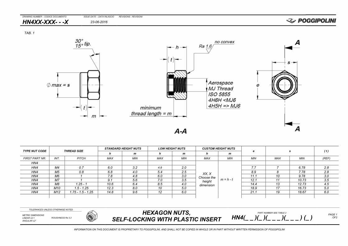
HN4XX-XXX- - -X 23-06-2016
TOLERANCES UNLESS OTHERWISE NOTED
HEXAGON NUTS,
SELF-LOCKING WITH PLASTIC INSERT PART NUMBER SEE TABLE 2
HN4(_ _ )(_ )(_ _ _ )(_ _ _ ) (_ ) PAGE 1
OF2 METRIC DIMENSIONS LINEAR ±0.1 ANGULAR ±2°
ROUGHNESS Ra 3.2
INFORMATION ON THIS DOCUMENT IS PROPRIETARY TO POGGIPOLINI, AND SHALL NOT BE COPIED IN WHOLE OR IN PART WITHOUT WRITTEN PERMISSION OF POGGIPOLINI
TYPE NUT CODE THREAD SIZE STANDARD HEIGHT NUTS LOW HEIGHT NUTS CUSTOM HEIGHT NUTS
e s ( t ) h m h m h m
FIRST PART NR. INT. PITCH MAX MIN MAX MIN MAX MIN MIN MAX MIN (REF)
HN4
XX, X Choose the
height dimension
m = h - t
HN4 M4 0.7 6.0 3.2 4.8 2.0 7.7 7 6.78 2.8 HN4 M5 0.8 6.8 4.0 5.4 2.5 8.9 8 7.78 2.8 HN4 M6 1 7.8 4.8 6.0 3.0 11.1 10 9.78 3.0 HN4 M7 1 9.1 5.6 7.0 3.5 12.1 11 10.73 3.5 HN4 M8 1.25 - 1 10.6 6.4 8.5 4.0 14.4 13 12.73 4.5 HN4 M10 1.5 - 1.25 12.3 8.0 10 5.0 18.9 17 16.73 5.0 HN4 M12 1.75 - 1.5 - 1.25 14.8 9.6 12 6.0 21.1 19 18.67 6.0
TAB. 1

DRAWING NUMBER – CODICE DOCUMENTO ISSUE DATE – DATA RILASCIO REVISIONS - REVISIONI
HN4XX-XXX- - -X 23-06-2016
TOLERANCES UNLESS OTHERWISE NOTED
HEXAGON NUTS,
SELF-LOCKING WITH PLASTIC INSERT PART NUMBER SEE TABLE 2
HN4(_ _ )(_ )(_ _ _ )(_ _ _ ) (_ ) PAGE 2
OF2 METRIC DIMENSIONS LINEAR ±0.1 ANGULAR ±2°
ROUGHNESS Ra 3.2
INFORMATION ON THIS DOCUMENT IS PROPRIETARY TO POGGIPOLINI, AND SHALL NOT BE COPIED IN WHOLE OR IN PART WITHOUT WRITTEN PERMISSION OF POGGIPOLINI
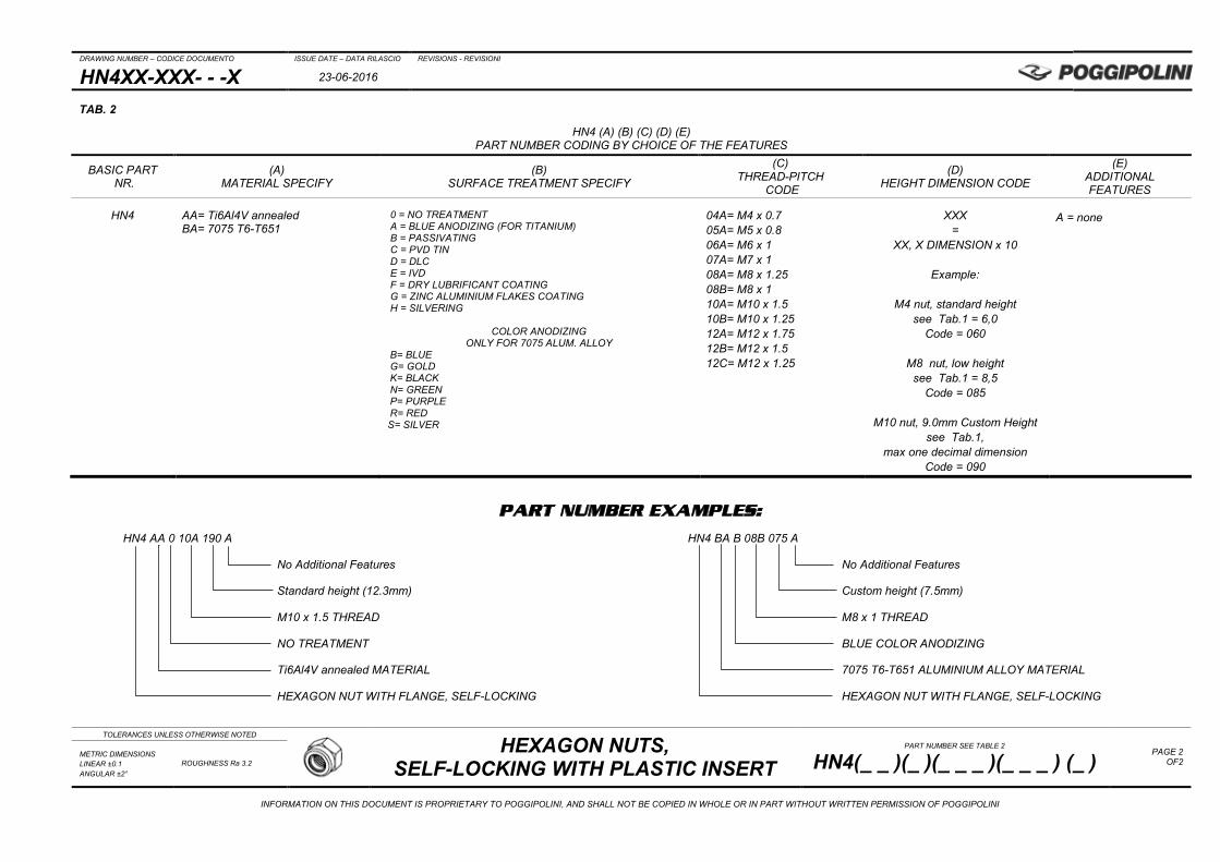
PART NUMBER EXAMPLES:
HN4 AA 0 10A 190 A HN4 BA B 08B 075 A
No Additional Features No Additional Features
Standard height (12.3mm) Custom height (7.5mm)
M10 x 1.5 THREAD M8 x 1 THREAD
NO TREATMENT BLUE COLOR ANODIZING
Ti6Al4V annealed MATERIAL 7075 T6-T651 ALUMINIUM ALLOY MATERIAL
HEXAGON NUT WITH FLANGE, SELF-LOCKING HEXAGON NUT WITH FLANGE, SELF-LOCKING
TAB. 2
HN4 (A) (B) (C) (D) (E) PART NUMBER CODING BY CHOICE OF THE FEATURES
BASIC PART NR.
(A) MATERIAL SPECIFY
(B) SURFACE TREATMENT SPECIFY
(C) THREAD-PITCH
CODE
(D) HEIGHT DIMENSION CODE
(E) ADDITIONAL FEATURES
HN4
AA= Ti6Al4V annealed BA= 7075 T6-T651
0 = NO TREATMENT A = BLUE ANODIZING (FOR TITANIUM) B = PASSIVATING C = PVD TIN D = DLC E = IVD F = DRY LUBRIFICANT COATING G = ZINC ALUMINIUM FLAKES COATING H = SILVERING
COLOR ANODIZING
ONLY FOR 7075 ALUM. ALLOY B= BLUE G= GOLD K= BLACK N= GREEN P= PURPLE R= RED S= SILVER
04A= M4 x 0.7 05A= M5 x 0.8 06A= M6 x 1 07A= M7 x 1 08A= M8 x 1.25 08B= M8 x 1 10A= M10 x 1.5 10B= M10 x 1.25 12A= M12 x 1.75 12B= M12 x 1.5 12C= M12 x 1.25
XXX =
XX, X DIMENSION x 10
Example:
M4 nut, standard height see Tab.1 = 6,0
Code = 060
M8 nut, low height see Tab.1 = 8,5
Code = 085
M10 nut, 9.0mm Custom Height see Tab.1,
max one decimal dimension Code = 090
A = none
DRAWING NUMBER – CODICE DOCUMENTO ISSUE DATE – DATA RILASCIO REVISIONS - REVISIONI
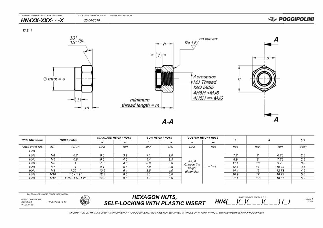
HN4XX-XXX- - -X 23-06-2016
TOLERANCES UNLESS OTHERWISE NOTED
HEXAGON NUTS,
SELF-LOCKING WITH PLASTIC INSERT PART NUMBER SEE TABLE 2
HN4(_ _ )(_ )(_ _ _ )(_ _ _ ) (_ ) PAGE 1
OF2 METRIC DIMENSIONS LINEAR ±0.1 ANGULAR ±2°
ROUGHNESS Ra 3.2
INFORMATION ON THIS DOCUMENT IS PROPRIETARY TO POGGIPOLINI, AND SHALL NOT BE COPIED IN WHOLE OR IN PART WITHOUT WRITTEN PERMISSION OF POGGIPOLINI
TYPE NUT CODE THREAD SIZE STANDARD HEIGHT NUTS LOW HEIGHT NUTS CUSTOM HEIGHT NUTS
e s ( t ) h m h m h m
FIRST PART NR. INT. PITCH MAX MIN MAX MIN MAX MIN MIN MAX MIN (REF)
HN4
XX, X Choose the
height dimension
m = h - t
HN4 M4 0.7 6.0 3.2 4.8 2.0 7.7 7 6.78 2.8 HN4 M5 0.8 6.8 4.0 5.4 2.5 8.9 8 7.78 2.8 HN4 M6 1 7.8 4.8 6.0 3.0 11.1 10 9.78 3.0 HN4 M7 1 9.1 5.6 7.0 3.5 12.1 11 10.73 3.5 HN4 M8 1.25 - 1 10.6 6.4 8.5 4.0 14.4 13 12.73 4.5 HN4 M10 1.5 - 1.25 12.3 8.0 10 5.0 18.9 17 16.73 5.0 HN4 M12 1.75 - 1.5 - 1.25 14.8 9.6 12 6.0 21.1 19 18.67 6.0
TAB. 1
DRAWING NUMBER – CODICE DOCUMENTO ISSUE DATE – DATA RILASCIO REVISIONS - REVISIONI
HN4XX-XXX- - -X 23-06-2016
TOLERANCES UNLESS OTHERWISE NOTED
HEXAGON NUTS,
SELF-LOCKING WITH PLASTIC INSERT PART NUMBER SEE TABLE 2
HN4(_ _ )(_ )(_ _ _ )(_ _ _ ) (_ ) PAGE 2
OF2 METRIC DIMENSIONS LINEAR ±0.1 ANGULAR ±2°
ROUGHNESS Ra 3.2
INFORMATION ON THIS DOCUMENT IS PROPRIETARY TO POGGIPOLINI, AND SHALL NOT BE COPIED IN WHOLE OR IN PART WITHOUT WRITTEN PERMISSION OF POGGIPOLINI
PART NUMBER EXAMPLES:
HN4 AA 0 10A 190 A HN4 BA B 08B 075 A
No Additional Features No Additional Features
Standard height (12.3mm) Custom height (7.5mm)
M10 x 1.5 THREAD M8 x 1 THREAD
NO TREATMENT BLUE COLOR ANODIZING
Ti6Al4V annealed MATERIAL 7075 T6-T651 ALUMINIUM ALLOY MATERIAL
HEXAGON NUT WITH FLANGE, SELF-LOCKING HEXAGON NUT WITH FLANGE, SELF-LOCKING
TAB. 2
HN4 (A) (B) (C) (D) (E) PART NUMBER CODING BY CHOICE OF THE FEATURES
BASIC PART NR.
(A) MATERIAL SPECIFY
(B) SURFACE TREATMENT SPECIFY
(C) THREAD-PITCH
CODE
(D) HEIGHT DIMENSION CODE
(E) ADDITIONAL FEATURES
HN4
AA= Ti6Al4V annealed BA= 7075 T6-T651
0 = NO TREATMENT A = BLUE ANODIZING (FOR TITANIUM) B = PASSIVATING C = PVD TIN D = DLC E = IVD F = DRY LUBRIFICANT COATING G = ZINC ALUMINIUM FLAKES COATING H = SILVERING
COLOR ANODIZING
ONLY FOR 7075 ALUM. ALLOY B= BLUE G= GOLD K= BLACK N= GREEN P= PURPLE R= RED S= SILVER
04A= M4 x 0.7 05A= M5 x 0.8 06A= M6 x 1 07A= M7 x 1 08A= M8 x 1.25 08B= M8 x 1 10A= M10 x 1.5 10B= M10 x 1.25 12A= M12 x 1.75 12B= M12 x 1.5 12C= M12 x 1.25
XXX =
XX, X DIMENSION x 10
Example:
M4 nut, standard height see Tab.1 = 6,0
Code = 060
M8 nut, low height see Tab.1 = 8,5
Code = 085
M10 nut, 9.0mm Custom Height see Tab.1,
max one decimal dimension Code = 090
A = none
DRAWING NUMBER – CODICE DOCUMENTO ISSUE DATE – DATA RILASCIO REVISIONS - REVISIONI
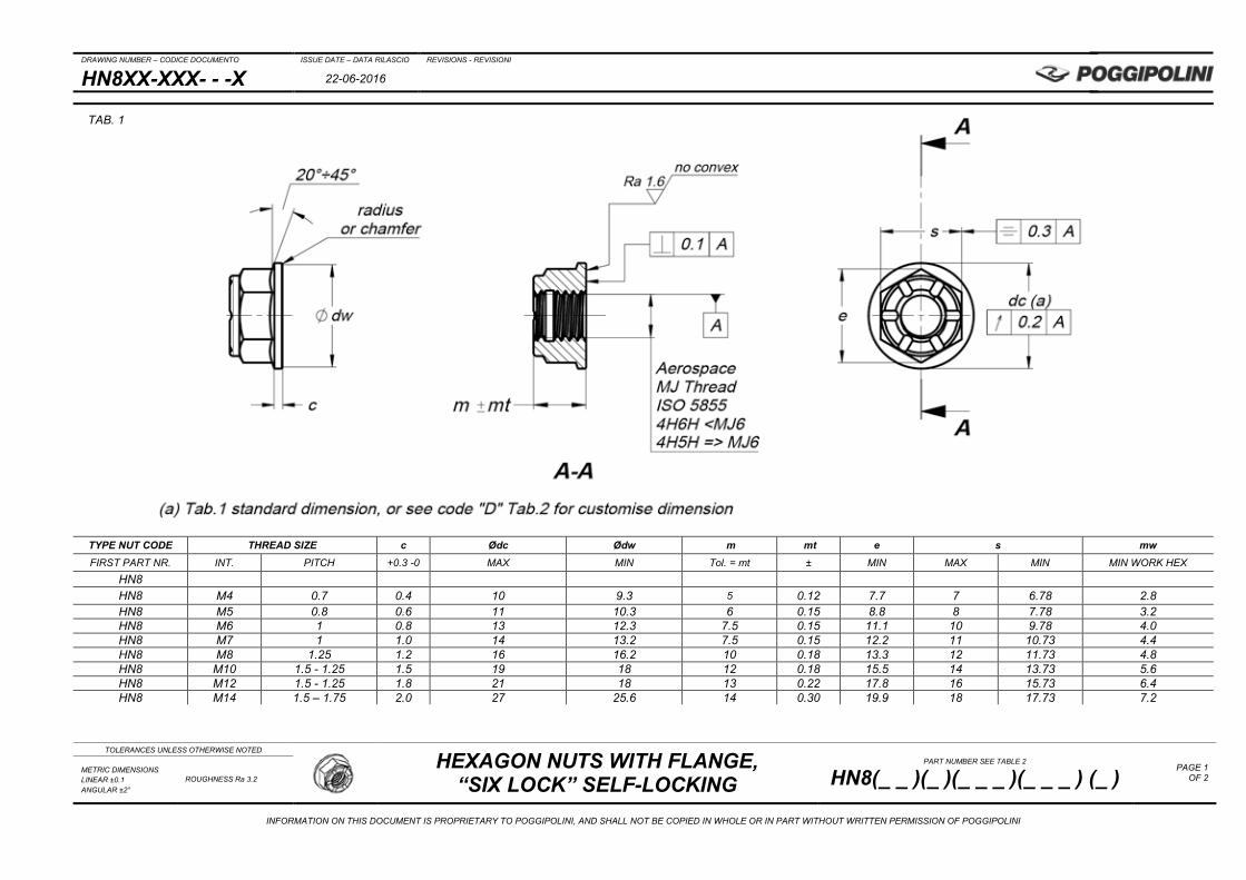
HN8XX-XXX- - -X 22-06-2016
TOLERANCES UNLESS OTHERWISE NOTED
HEXAGON NUTS WITH FLANGE, “SIX LOCK” SELF-LOCKING
PART NUMBER SEE TABLE 2
HN8(_ _ )(_ )(_ _ _ )(_ _ _ ) (_ ) PAGE 1
OF 2 METRIC DIMENSIONS LINEAR ±0.1 ANGULAR ±2°
ROUGHNESS Ra 3.2
INFORMATION ON THIS DOCUMENT IS PROPRIETARY TO POGGIPOLINI, AND SHALL NOT BE COPIED IN WHOLE OR IN PART WITHOUT WRITTEN PERMISSION OF POGGIPOLINI
TYPE NUT CODE THREAD SIZE c Ødc Ødw m mt e s mw FIRST PART NR. INT. PITCH +0.3 -0 MAX MIN Tol. = mt ± MIN MAX MIN MIN WORK HEX
HN8 HN8 M4 0.7 0.4 10 9.3 5 0.12 7.7 7 6.78 2.8 HN8 M5 0.8 0.6 11 10.3 6 0.15 8.8 8 7.78 3.2 HN8 M6 1 0.8 13 12.3 7.5 0.15 11.1 10 9.78 4.0 HN8 M7 1 1.0 14 13.2 7.5 0.15 12.2 11 10.73 4.4 HN8 M8 1.25 1.2 16 16.2 10 0.18 13.3 12 11.73 4.8 HN8 M10 1.5 - 1.25 1.5 19 18 12 0.18 15.5 14 13.73 5.6 HN8 M12 1.5 - 1.25 1.8 21 18 13 0.22 17.8 16 15.73 6.4 HN8 M14 1.5 – 1.75 2.0 27 25.6 14 0.30 19.9 18 17.73 7.2
TAB. 1
DRAWING NUMBER – CODICE DOCUMENTO ISSUE DATE – DATA RILASCIO REVISIONS - REVISIONI
HN8XX-XXX- - -X 22-06-2016
TOLERANCES UNLESS OTHERWISE NOTED
HEXAGON NUTS WITH FLANGE, “SIX LOCK” SELF-LOCKING
PART NUMBER SEE TABLE 2
HN8(_ _ )(_ )(_ _ _ )(_ _ _ ) (_ ) PAGE 2
OF 2 METRIC DIMENSIONS LINEAR ±0.1 ANGULAR ±2°
ROUGHNESS Ra 3.2
INFORMATION ON THIS DOCUMENT IS PROPRIETARY TO POGGIPOLINI, AND SHALL NOT BE COPIED IN WHOLE OR IN PART WITHOUT WRITTEN PERMISSION OF POGGIPOLINI
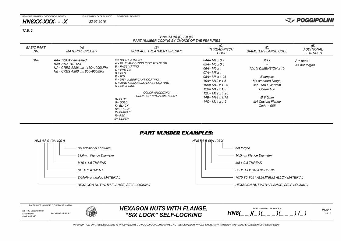
PART NUMBER EXAMPLES:
HN8 AA 0 10A 190 A HN8 BA B 05A 105 X
No Additional Features not forged
19.0mm Flange Diameter 10,5mm Flange Diameter
M10 x 1.5 THREAD M5 x 0.8 THREAD
NO TREATMENT BLUE COLOR ANODIZING
Ti6Al4V annealed MATERIAL 7075 T6-T651 ALUMINIUM ALLOY MATERIAL
HEXAGON NUT WITH FLANGE, SELF-LOCKING HEXAGON NUT WITH FLANGE, SELF-LOCKING
TAB. 2
HN8 (A) (B) (C) (D) (E) PART NUMBER CODING BY CHOICE OF THE FEATURES
BASIC PART NR.
(A) MATERIAL SPECIFY
(B) SURFACE TREATMENT SPECIFY
(C) THREAD-PITCH
CODE
(D) DIAMETER FLANGE CODE
(E) ADDITIONAL FEATURES
HN8
AA= Ti6Al4V annealed BA= 7075 T6-T651 NA= CRES A286 uts 1150÷1200MPa NB= CRES A286 uts 850÷900MPa
0 = NO TREATMENT A = BLUE ANODIZING (FOR TITANIUM) B = PASSIVATING C = PVD TIN D = DLC E = IVD F = DRY LUBRIFICANT COATING G = ZINC ALUMINIUM FLAKES COATING H = SILVERING
COLOR ANODIZING
ONLY FOR 7075 ALUM. ALLOY B= BLUE G= GOLD K= BLACK N= GREEN P= PURPLE R= RED S= SILVER
04A= M4 x 0.7 05A= M5 x 0.8 06A= M6 x 1 07A= M7 x 1 08A= M8 x 1.25 10A= M10 x 1.5 10B= M10 x 1.25 12B= M12 x 1.5 12C= M12 x 1.25 14B= M14 x 1.75 14C= M14 x 1.5
XXX =
XX, X DIMENSION x 10
Example: M4 standard flange, see Tab.1 Ø10mm
Code= 100
Ø 8.5mm M4 Custom Flange
Code = 085
A = none X= not forged

DRAWING NUMBER – CODICE DOCUMENTO ISSUE DATE – DATA RILASCIO REVISIONS - REVISIONI
HD2XX-XXX- - -X 22-06-2016
TOLERANCES UNLESS OTHERWISE NOTED
DOUBLE HEX NUTS WITH FLANGE, “SIX LOCK” SELF-LOCKING
PART NUMBER SEE TABLE 2
HD2(_ _ )(_ )(_ _ _ )(_ _ _ ) (_ ) PAGE 1
OF 2 METRIC DIMENSIONS LINEAR ±0.1 ANGULAR ±2°
ROUGHNESS Ra 3.2
INFORMATION ON THIS DOCUMENT IS PROPRIETARY TO POGGIPOLINI, AND SHALL NOT BE COPIED IN WHOLE OR IN PART WITHOUT WRITTEN PERMISSION OF POGGIPOLINI
TYPE NUT CODE THREAD SIZE c Ødc Ødw m mt e s mw FIRST PART NR. INT. PITCH +0.3 -0 MAX MIN Tol. = mt ± MIN MAX MIN MIN WORK HEX
HD2 HD2 M4 0.7 0.4 10 9.3 5 0.12 7.7 7 6.78 2.8 HD2 M5 0.8 0.6 11 10.3 6 0.15 8.8 8 7.78 3.2 HD2 M6 1 0.8 13 12.3 7.5 0.15 11.1 10 9.78 4.0 HD2 M7 1 1.0 14 13.2 7.5 0.15 12.2 11 10.73 4.4 HD2 M8 1.25 1.2 16 16.2 10 0.18 13.3 12 11.73 4.8 HD2 M10 1.5 - 1.25 1.5 19 18 12 0.18 15.5 14 13.73 5.6 HD2 M12 1.5 - 1.25 1.8 21 18 13 0.22 17.8 16 15.73 6.4 HD2 M14 1.5 – 1.75 2.0 27 25.6 14 0.30 19.9 18 17.73 7.2
TAB. 1

DRAWING NUMBER – CODICE DOCUMENTO ISSUE DATE – DATA RILASCIO REVISIONS - REVISIONI
HD2XX-XXX- - -X 22-06-2016
TOLERANCES UNLESS OTHERWISE NOTED
DOUBLE HEX NUTS WITH FLANGE, “SIX LOCK” SELF-LOCKING
PART NUMBER SEE TABLE 2
HD2(_ _ )(_ )(_ _ _ )(_ _ _ ) (_ ) PAGE 2
OF 2 METRIC DIMENSIONS LINEAR ±0.1 ANGULAR ±2°
ROUGHNESS Ra 3.2
INFORMATION ON THIS DOCUMENT IS PROPRIETARY TO POGGIPOLINI, AND SHALL NOT BE COPIED IN WHOLE OR IN PART WITHOUT WRITTEN PERMISSION OF POGGIPOLINI
PART NUMBER EXAMPLES:
HD2 AA 0 10A 190 A HD2 BA B 05A 105 A
No Additional Features No Additional Features
19.0mm Flange Diameter 10,5mm Flange Diameter
M10 x 1.5 THREAD M5 x 0.8 THREAD
NO TREATMENT BLUE COLOR ANODIZING
Ti6Al4V annealed MATERIAL 7075 T6-T651 ALUMINIUM ALLOY MATERIAL
DOUBLE HEXAGON NUT WITH FLANGE, SELF-LOCKING DOUBLE HEXAGON NUT WITH FLANGE, SELF-LOCKING
TAB. 2
HD2 (A) (B) (C) (D) (E) PART NUMBER CODING BY CHOICE OF THE FEATURES
BASIC PART NR.
(A) MATERIAL SPECIFY
(B) SURFACE TREATMENT SPECIFY
(C) THREAD-PITCH
CODE
(D) DIAMETER FLANGE CODE
(E) ADDITIONAL FEATURES
HD2
AA= Ti6Al4V annealed BA= 7075 T6-T651 NA= CRES A286 uts 1150÷1200MPa NB= CRES A286 uts 850÷900MPa
0 = NO TREATMENT A = BLUE ANODIZING (FOR TITANIUM) B = PASSIVATING C = PVD TIN D = DLC E = IVD F = DRY LUBRIFICANT COATING G = ZINC ALUMINIUM FLAKES COATING H = SILVERING
COLOR ANODIZING
ONLY FOR 7075 ALUM. ALLOY B= BLUE G= GOLD K= BLACK N= GREEN P= PURPLE R= RED S= SILVER
04A= M4 x 0.7 05A= M5 x 0.8 06A= M6 x 1 07A= M7 x 1 08A= M8 x 1.25 10A= M10 x 1.5 10B= M10 x 1.25 12B= M12 x 1.5 12C= M12 x 1.25 14B= M14 x 1.75 14C= M14 x 1.5
XXX =
XX, X DIMENSION x 10
Example: M4 standard flange, see Tab.1 Ø10mm
Code= 100
Ø 8.5mm M4 Custom Flange
Code = 085
A = none X= not forged

DRAWING NUMBER – CODICE DOCUMENTO ISSUE DATE – DATA RILASCIO REVISIONS - REVISIONI
HN5XX-XXX- - -X 21-06-2016
TOLERANCES UNLESS OTHERWISE NOTED
HEXAGON NUTS WITH FLANGE, SELF-LOCKING, HEAT RESISTING STEEL
PART NUMBER SEE TABLE 2
HN5(_ _ )(_ )(_ _ _ )(_ _ _ ) (_ ) PAGE 1
OF 2 METRIC DIMENSIONS LINEAR ±0.1 ANGULAR ±2°
ROUGHNESS Ra 3.2
INFORMATION ON THIS DOCUMENT IS PROPRIETARY TO POGGIPOLINI, AND SHALL NOT BE COPIED IN WHOLE OR IN PART WITHOUT WRITTEN PERMISSION OF POGGIPOLINI
TYPE NUT CODE THREAD SIZE c Ødc Ødw m mt e s mw FIRST PART NR. INT. PITCH +0.3 -0 MAX MIN Tol. = mt ± MIN MAX MIN MIN WORK HEX
HN5
HN5
HN5 M5 0.8 1.0 9.1 8.3 5.5 0.15 7.69 7 6.78 2.8 HN5 M6 1 1.2 10.6 9.8 6.3 0.15 8.79 8 7.78 3.2 HN5 M7 1 1.4 12.1 11.3 6.5 0.15 9.89 9 8.78 3.6 HN5 M8 1.25 1.6 13.6 12.8 6.8 0.18 10.98 10 9.73 4.0 HN5 M10 1.5 - 1.25 2.0 16.7 15.7 7.8 0.18 13.19 12 11.73 4.8 HN5 M12 1.5 – 1.25 2.4 19.9 18.8 9.0 0.22 15.38 14 13.73 5.6
TAB. 1
DRAWING NUMBER – CODICE DOCUMENTO ISSUE DATE – DATA RILASCIO REVISIONS - REVISIONI
HN5XX-XXX- - -X 21-06-2016
TOLERANCES UNLESS OTHERWISE NOTED
HEXAGON NUTS WITH FLANGE, SELF-LOCKING, HEAT RESISTING STEEL
PART NUMBER SEE TABLE 2
HN5(_ _ )(_ )(_ _ _ )(_ _ _ ) (_ ) PAGE 2
OF 2 METRIC DIMENSIONS LINEAR ±0.1 ANGULAR ±2°
ROUGHNESS Ra 3.2
INFORMATION ON THIS DOCUMENT IS PROPRIETARY TO POGGIPOLINI, AND SHALL NOT BE COPIED IN WHOLE OR IN PART WITHOUT WRITTEN PERMISSION OF POGGIPOLINI
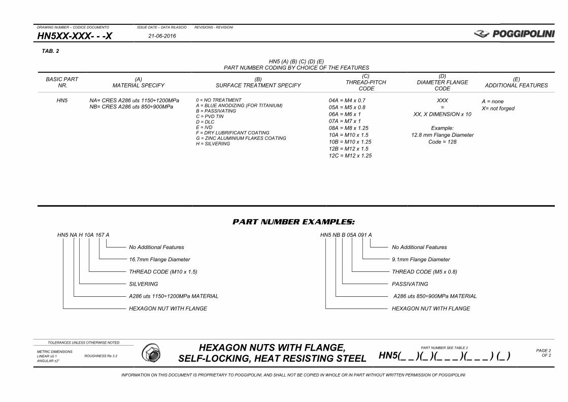
PART NUMBER EXAMPLES:
HN5 NA H 10A 167 A HN5 NB B 05A 091 A
No Additional Features No Additional Features
16.7mm Flange Diameter 9.1mm Flange Diameter
THREAD CODE (M10 x 1.5) THREAD CODE (M5 x 0.8)
SILVERING PASSIVATING
A286 uts 1150÷1200MPa MATERIAL A286 uts 850÷900MPa MATERIAL
HEXAGON NUT WITH FLANGE HEXAGON NUT WITH FLANGE
TAB. 2
HN5 (A) (B) (C) (D) (E) PART NUMBER CODING BY CHOICE OF THE FEATURES
BASIC PART NR.
(A) MATERIAL SPECIFY
(B) SURFACE TREATMENT SPECIFY
(C) THREAD-PITCH
CODE
(D) DIAMETER FLANGE
CODE
(E) ADDITIONAL FEATURES
HN5
NA= CRES A286 uts 1150÷1200MPa NB= CRES A286 uts 850÷900MPa
0 = NO TREATMENT A = BLUE ANODIZING (FOR TITANIUM) B = PASSIVATING C = PVD TIN D = DLC E = IVD F = DRY LUBRIFICANT COATING G = ZINC ALUMINIUM FLAKES COATING H = SILVERING
04A = M4 x 0.7 05A = M5 x 0.8 06A = M6 x 1 07A = M7 x 1 08A = M8 x 1.25 10A = M10 x 1.5 10B = M10 x 1.25 12B = M12 x 1.5 12C = M12 x 1.25
XXX =
XX, X DIMENSION x 10
Example: 12.8 mm Flange Diameter
Code = 128
A = none X= not forged
DRAWING NUMBER – CODICE DOCUMENTO ISSUE DATE – DATA RILASCIO REVISIONS - REVISIONI
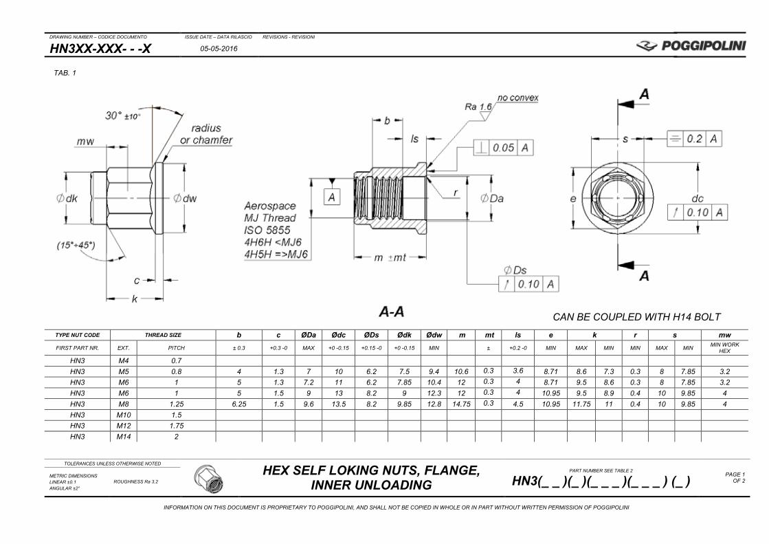
HN3XX-XXX- - -X 05-05-2016
TOLERANCES UNLESS OTHERWISE NOTED
HEX SELF LOKING NUTS, FLANGE, INNER UNLOADING
PART NUMBER SEE TABLE 2
HN3(_ _ )(_ )(_ _ _ )(_ _ _ ) (_ ) PAGE 1
OF 2 METRIC DIMENSIONS LINEAR ±0.1 ANGULAR ±2°
ROUGHNESS Ra 3.2
INFORMATION ON THIS DOCUMENT IS PROPRIETARY TO POGGIPOLINI, AND SHALL NOT BE COPIED IN WHOLE OR IN PART WITHOUT WRITTEN PERMISSION OF POGGIPOLINI
TYPE NUT CODE THREAD SIZE b c ØDa Ødc ØDs Ødk Ødw m mt ls e k r s mw FIRST PART NR. EXT. PITCH ± 0.3 +0.3 -0 MAX +0 -0.15 +0.15 -0 +0 -0.15 MIN ± +0.2 -0 MIN MAX MIN MIN MAX MIN MIN WORK
HEX
HN3 M4 0.7 HN3 M5 0.8 4 1.3 7 10 6.2 7.5 9.4 10.6 0.3 3.6 8.71 8.6 7.3 0.3 8 7.85 3.2 HN3 M6 1 5 1.3 7.2 11 6.2 7.85 10.4 12 0.3 4 8.71 9.5 8.6 0.3 8 7.85 3.2 HN3 M6 1 5 1.5 9 13 8.2 9 12.3 12 0.3 4 10.95 9.5 8.9 0.4 10 9.85 4 HN3 M8 1.25 6.25 1.5 9.6 13.5 8.2 9.85 12.8 14.75 0.3 4.5 10.95 11.75 11 0.4 10 9.85 4 HN3 M10 1.5 HN3 M12 1.75 HN3 M14 2
TAB. 1
CAN BE COUPLED WITH H14 BOLT

DRAWING NUMBER – CODICE DOCUMENTO ISSUE DATE – DATA RILASCIO REVISIONS - REVISIONI
HN3XX-XXX- - -X 05-05-2016
TOLERANCES UNLESS OTHERWISE NOTED
HEX SELF LOKING NUTS, FLANGE, INNER UNLOADING
PART NUMBER SEE TABLE 2
HN3(_ _ )(_ )(_ _ _ )(_ _ _ ) (_ ) PAGE 2
OF 2 METRIC DIMENSIONS LINEAR ±0.1 ANGULAR ±2°
ROUGHNESS Ra 3.2
INFORMATION ON THIS DOCUMENT IS PROPRIETARY TO POGGIPOLINI, AND SHALL NOT BE COPIED IN WHOLE OR IN PART WITHOUT WRITTEN PERMISSION OF POGGIPOLINI
PART NUMBER EXAMPLES:
HN3 NC F 08A 082 A HN3 NA H 05A 062 A
No Additional Features No Additional Features
TAB.1 “Ds” IN. UNLOADING 8,2mm DIAMETER TAB.1 “Ds” IN. UNLOADING 6,2mm DIAMETER
THREAD CODE (M8 x 1.25) THREAD CODE (M5 x 0.8)
WITH DRY LUBRIFICANT PASSIVATING
AISI 303 MATERIAL A286 1150÷1200MPa MATERIAL
NUT, HEXAGON HEAD, FLANGE, INNER UNLOADING NUT, HEXAGON HEAD, FLANGE, INNER UNLOADING
TAB. 2
HN3 (A) (B) (C) (D) (E) PART NUMBER CODING BY CHOICE OF THE FEATURES
BASIC PART NR.
(A) MATERIAL SPECIFY
(B) SURFACE TREATMENT SPECIFY
(C) THREAD-PITCH
CODE
(D) INNER UNLOADING
DIA CODE (CODE = ØDs)
(E) ADDITIONAL FEATURES
HN3
AA = TI6AL4V ANN. BA = AL 7075 T6-T651 CA = AL 7068 T6511 NA = A286 1150÷1200MPa NB = A286 850÷900MPa NC = AISI 303
0 = NO TREATMENT A = BLUE ANODIZING (FOR TITANIUM) B = PASSIVATING C = PVD TIN D = DLC E = IVD F = DRY LUBRIFICANT COATING G = ZINC ALUMINIUM FLAKES COATING H = ARGENTATURA
04A = M4 x 0.7 05A = M5 x 0.8 06A = M6 x 1 07A = M7 x 1 08A = M8 x 1.25 08B = M8 x 1 10A = M10 x 1.5 10B = M10 x 1.25 12A = M12 x 1.75 12B = M12 x 1.5 12C = M12 x 1.25 14A = M14 x 2 14B = M14 x 1.75 14C = M 14 x 1.5 14D = M 14 x 1.25 16A = M 16 x 2 16B = M16 x 1.75 16C = M16 x 1.5
062 = 6,2mm 082 = 8,2mm
A = none
COLOR ANODIZING
ONLY FOR 7075 ALUM. ALLOY B= BLUE G= GOLD K= BLACK N= GREEN P= PURPLE R= RED S= SILVER
DRAWING NUMBER – CODICE DOCUMENTO ISSUE DATE – DATA RILASCIO REVISIONS - REVISIONI
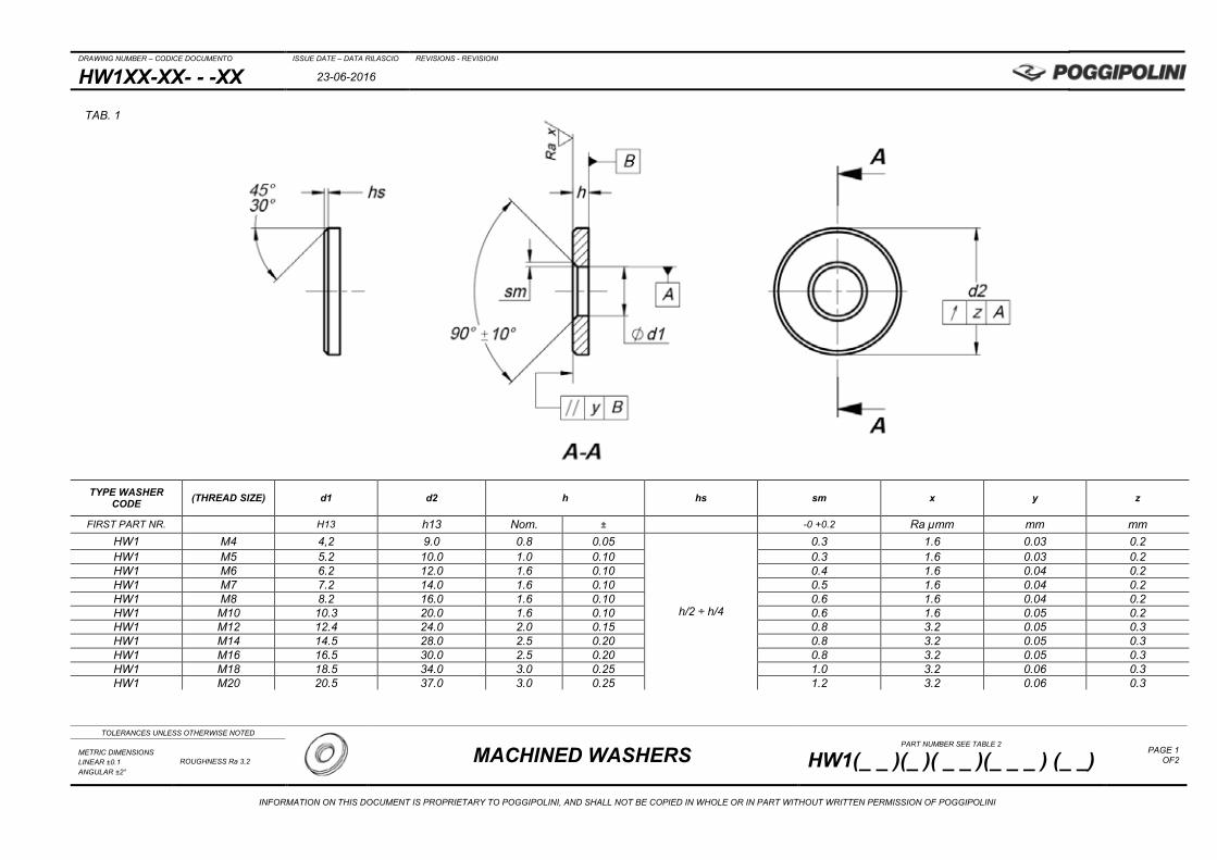
HW1XX-XX- - -XX 23-06-2016
TOLERANCES UNLESS OTHERWISE NOTED
MACHINED WASHERS
PART NUMBER SEE TABLE 2
HW1(_ _ )(_ )( _ _ )(_ _ _ ) (_ _) PAGE 1
OF2 METRIC DIMENSIONS LINEAR ±0.1 ANGULAR ±2°
ROUGHNESS Ra 3.2
INFORMATION ON THIS DOCUMENT IS PROPRIETARY TO POGGIPOLINI, AND SHALL NOT BE COPIED IN WHOLE OR IN PART WITHOUT WRITTEN PERMISSION OF POGGIPOLINI
TYPE WASHER CODE (THREAD SIZE) d1 d2 h hs sm x y z
FIRST PART NR. H13 h13 Nom. ± -0 +0.2 Ra µmm mm mm HW1 M4 4,2 9.0 0.8 0.05
h/2 ÷ h/4
0.3 1.6 0.03 0.2 HW1 M5 5.2 10.0 1.0 0.10 0.3 1.6 0.03 0.2 HW1 M6 6.2 12.0 1.6 0.10 0.4 1.6 0.04 0.2 HW1 M7 7.2 14.0 1.6 0.10 0.5 1.6 0.04 0.2 HW1 M8 8.2 16.0 1.6 0.10 0.6 1.6 0.04 0.2 HW1 M10 10.3 20.0 1.6 0.10 0.6 1.6 0.05 0.2 HW1 M12 12.4 24.0 2.0 0.15 0.8 3.2 0.05 0.3 HW1 M14 14.5 28.0 2.5 0.20 0.8 3.2 0.05 0.3 HW1 M16 16.5 30.0 2.5 0.20 0.8 3.2 0.05 0.3 HW1 M18 18.5 34.0 3.0 0.25 1.0 3.2 0.06 0.3 HW1 M20 20.5 37.0 3.0 0.25 1.2 3.2 0.06 0.3
TAB. 1
DRAWING NUMBER – CODICE DOCUMENTO ISSUE DATE – DATA RILASCIO REVISIONS - REVISIONI
HW1XX-XX- - -XX 23-06-2016
TOLERANCES UNLESS OTHERWISE NOTED
MACHINED WASHERS
PART NUMBER SEE TABLE 2
HW1(_ _ )(_ )( _ _ )(_ _ _ ) (_ _) PAGE 2
OF2 METRIC DIMENSIONS LINEAR ±0.1 ANGULAR ±2°
ROUGHNESS Ra 3.2
INFORMATION ON THIS DOCUMENT IS PROPRIETARY TO POGGIPOLINI, AND SHALL NOT BE COPIED IN WHOLE OR IN PART WITHOUT WRITTEN PERMISSION OF POGGIPOLINI
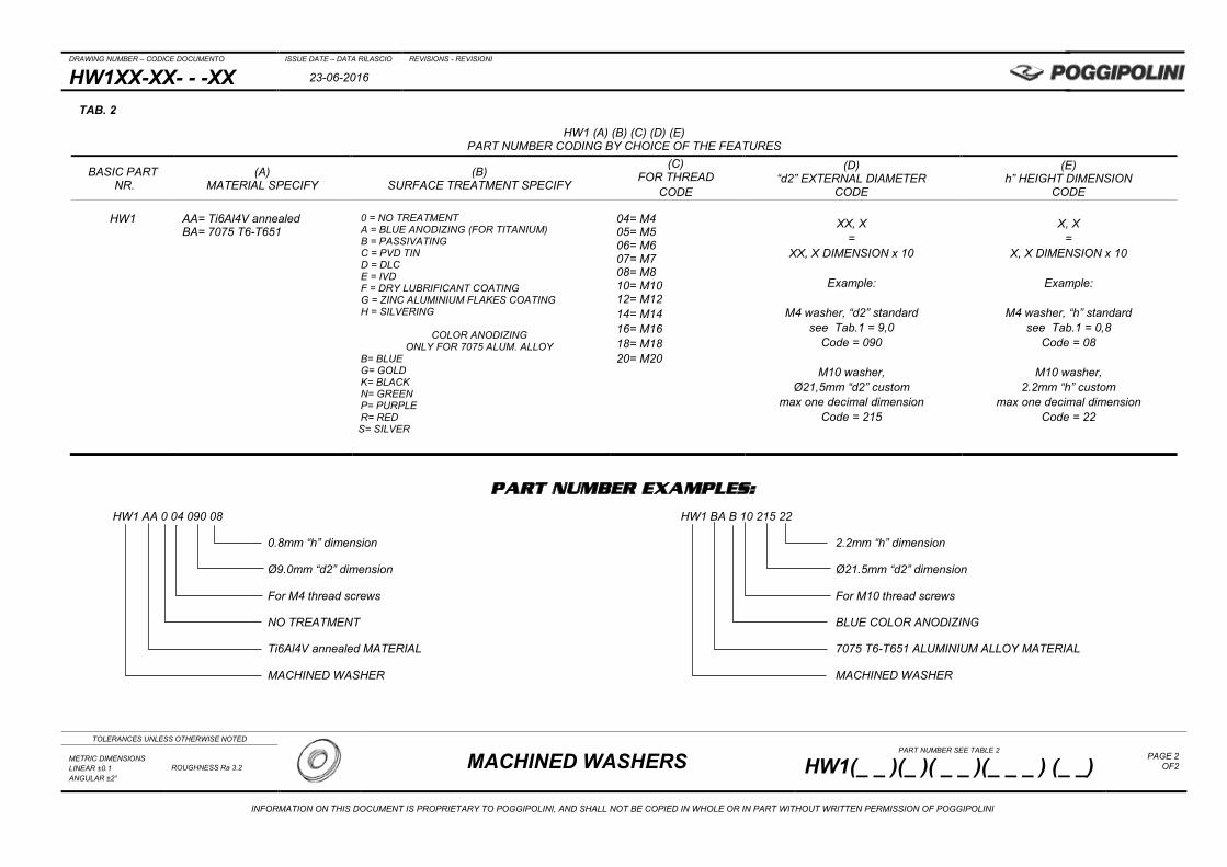
PART NUMBER EXAMPLES:
HW1 AA 0 04 090 08 HW1 BA B 10 215 22
0.8mm “h” dimension 2.2mm “h” dimension
Ø9.0mm “d2” dimension Ø21.5mm “d2” dimension
For M4 thread screws For M10 thread screws
NO TREATMENT BLUE COLOR ANODIZING
Ti6Al4V annealed MATERIAL 7075 T6-T651 ALUMINIUM ALLOY MATERIAL
MACHINED WASHER MACHINED WASHER
TAB. 2
HW1 (A) (B) (C) (D) (E) PART NUMBER CODING BY CHOICE OF THE FEATURES
BASIC PART NR.
(A) MATERIAL SPECIFY
(B) SURFACE TREATMENT SPECIFY
(C) FOR THREAD
CODE
(D) “d2” EXTERNAL DIAMETER
CODE
(E) h” HEIGHT DIMENSION
CODE
HW1
AA= Ti6Al4V annealed BA= 7075 T6-T651
0 = NO TREATMENT A = BLUE ANODIZING (FOR TITANIUM) B = PASSIVATING C = PVD TIN D = DLC E = IVD F = DRY LUBRIFICANT COATING G = ZINC ALUMINIUM FLAKES COATING H = SILVERING
COLOR ANODIZING
ONLY FOR 7075 ALUM. ALLOY B= BLUE G= GOLD K= BLACK N= GREEN P= PURPLE R= RED S= SILVER
04= M4 05= M5 06= M6 07= M7 08= M8 10= M10 12= M12 14= M14 16= M16 18= M18 20= M20
XX, X
= XX, X DIMENSION x 10
Example:
M4 washer, “d2” standard
see Tab.1 = 9,0 Code = 090
M10 washer,
Ø21,5mm “d2” custom max one decimal dimension
Code = 215
X, X
= X, X DIMENSION x 10
Example:
M4 washer, “h” standard
see Tab.1 = 0,8 Code = 08
M10 washer,
2.2mm “h” custom max one decimal dimension
Code = 22
APPENDIX
01/20 editionThis document is propietary to POGGIPOLINI S.r.l.
and shall not be copied or used without written consensus.
3.0
3.1 MATERIALS
APPENDIX
Since 1950 Poggipolini has acquired considerable expertise on various types of materials.
Poggipolini is capable to work and find the best applications for the following materials:
53
MP35NAISI 4340Ti6Al4V
Maraging 300MLX 1713-8 PH
AL7075 T6/T651Inconel 71815-5 PH
AL7068 T6511Aermet 10017-4 PH

54
3.2 TITANIUM Ti6Al4V
Titanium is available on the market as commercially pure or as alloys.
Commercially pure titanium has a hexagonal Alfa type crystalline structure and increases its mechanical re-sistance (ultimate strength psi) with each grade classification (from grade 1 to grade 4). With the addition of alloying elements such as aluminium, vanadium, and molybdenum, titanium alloys are created which have cubic Alfa + Beta crystalline structures. These Alfa + Beta alloys are the most used commercially, due to their ductile-weight-mechanical resistance relationships.Of these, the most used titanium alloys are 6Al4V (grade 5) and 3Al 2,5V (grade 9) which are used to make bolts, mechanical components and chassis.
Titanium and its alloys are used in all those fields in which one or more of the following factors are important: high strength-to-weight ratio, mechanical resistance, corrosive resistance, electrical resistivity.
Titanium and titanium alloys owe their excellent corrosion resistance to a stable, protective surface layer of titanium oxide; titanium alloys are highly resistant to pitting corrosion, and it is rarely encountered.

55
Titanium alloys are highly resistant to pitting corrosion, and it is rarely encountered.
The commercially pure titanium alloys (grades 1, 2, 7, 11, 12) are immune to SCC except in a few environments, such as anhydrous methanol solutions containing halides, nitrogen tetroxide and red fuming nitric acid. The higher strength alloys have been found susceptible to SCC in aqueous chloride solutions at high stress levels in laboratory tests, but the problem is rarely encountered in practice.
3.3 CORROSION RESISTANT
Titanium and titanium alloys owe their excellent corrosion resistance to a stable, protective surface layer of titanium oxide. Titanium metal is highly reactive with oxygen, and the surface oxide forms spontaneously and instantaneously in contact with air and most media. Damage to the oxide film usually heals rapidly if the envi-ronment contains oxygen or moisture at the parts per million level. Hence titanium alloys are highly resistant to corrosion, usually corrode at negligible rates and require no corrosion allowance. However, anhydrous or highly reducing conditions may prevent the formation or healing of the oxide film, and corrosion may then become rapid. This form of corrosion resistance is similar to that of aluminium and magnesium alloys, and of stainless steels, which also rely on a protective oxide film on the surface of a reactive metal.
When titanium is fully passive, corrosion rates are typically lower than 0.04 mm/year, due to the highly stable surface protective film. In many environments the film may thicken, which gives interference colours and a slight weight gain. General corrosion may be encountered in reducing acid conditions, particularly at elevated temperatures. In strong and hot reducing acids the titanium oxide film can dissolve, and the unprotected tita-nium metal be taken rapidly into solution.
Pitting Corrosion
Stress Corrosion Cracking

56
Titanium rarely suffers accelerated corrosion on coupling with other metals, but it may accelerate the cor-rosion of a more active metal coupled to it. The rate of attack depends on many factors, including solution chemistry and temperature, and the cathode to anode surface area ratio. The coupling of titanium with dissimilar metals usually does not accelerate the corrosion of the titanium. The exception is in reducing environments where titanium does not passivate. Under these conditions, it has a po-tential similar to aluminum and will undergo accelerated corrosion when coupled to other more noble metals. Because titanium is usually the cathodic member of any galvanic couple, hydrogen will be evolved on its sur-face proportional to the galvanic current flow. This may result in the formation of surface hydride films that are generally stable and cause no problems. If the temperature is above 170°F (77°C), however, hydriding can cause embrittlement.
In order to avoid problems with galvanic corrosion, it is best to construct equipment of a single metal. If this is not practical, use two metals that are close together in the galvanic series, insulate the joint or cathodically protect the less noble metal. If dissimilar metals are necessary, construct the critical parts out of titanium, since it is usually not attacked, and use large areas of the less noble metal and heavy sections to allow for increased corrosion.
Galvanic Couples
The table above gives the galvanic series in seawater. In this environment, titanium is passive and exhibits a potential of about 0.0V versus a saturated calomel reference cell which places it high on the passive or noble end of the series. For most environments, titanium will be the cathodic member of any galvanic couple. It may accelerate the corrosion of the other member of the couple, but in most cases, the titanium will be unaffected.

57
The table above shows the accelerating effect that titanium has on the corrosion rate of various metals when they are galvanically connected in seawater.
If the area of the titanium exposed is small in relation to the area of the other metal, the effect on the corrosion rate is negligible. However, if the area of the titanium (cathode) greatly exceeds the area of the other metal (anode) severe corrosion may result.
The hardness of the surface oxide film gives excellent resistance to erosion corrosion, which is outstanding compared to most other candidates for heat exchanger service. High flow rates (30m/sec) can be used wi-thout problems due to inlet turbulence or pump cavitation effects.
The highly protective surface oxide film results in insignificant reductions in fatigue strength in water, sea water and most chloride solutions where corrosion is not active.
Titanium alloys corrode negligibly in sea water at temperatures up to 260°C. Even under biofouling and depo-sits, pitting and crevice corrosion are not encountered. Marine atmospheres, splash and tidal zones, and soils also have no effect. Corrosion at tight design crevices may be seen in waters with higher than about 1000 ppm of chlorides at temperatures above about 75°C.
Titanium alloys are highly resistant to oxidising acids, with corrosion rates typically less than 0.03 mm/year.
58
Erosion Corrosion
Fatigue Corrosion
Water & Sea Water
Oxidising Media
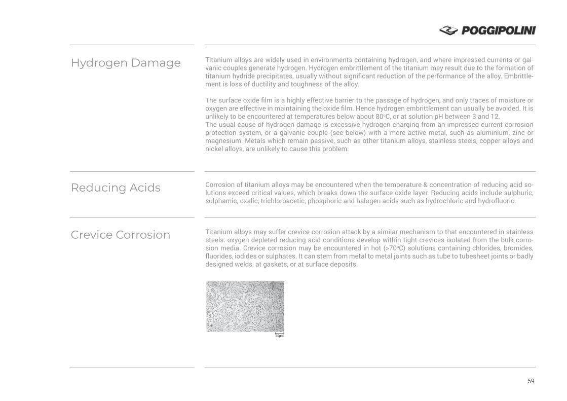
59
Titanium alloys are widely used in environments containing hydrogen, and where impressed currents or gal-vanic couples generate hydrogen. Hydrogen embrittlement of the titanium may result due to the formation of titanium hydride precipitates, usually without significant reduction of the performance of the alloy. Embrittle-ment is loss of ductility and toughness of the alloy.
The surface oxide film is a highly effective barrier to the passage of hydrogen, and only traces of moisture or oxygen are effective in maintaining the oxide film. Hence hydrogen embrittlement can usually be avoided. It is unlikely to be encountered at temperatures below about 80oC, or at solution pH between 3 and 12. The usual cause of hydrogen damage is excessive hydrogen charging from an impressed current corrosion protection system, or a galvanic couple (see below) with a more active metal, such as aluminium, zinc or magnesium. Metals which remain passive, such as other titanium alloys, stainless steels, copper alloys and nickel alloys, are unlikely to cause this problem.
Corrosion of titanium alloys may be encountered when the temperature & concentration of reducing acid so-lutions exceed critical values, which breaks down the surface oxide layer. Reducing acids include sulphuric, sulphamic, oxalic, trichloroacetic, phosphoric and halogen acids such as hydrochloric and hydrofluoric.
Titanium alloys may suffer crevice corrosion attack by a similar mechanism to that encountered in stainless steels: oxygen depleted reducing acid conditions develop within tight crevices isolated from the bulk corro-sion media. Crevice corrosion may be encountered in hot (>70oC) solutions containing chlorides, bromides, fluorides, iodides or sulphates. It can stem from metal to metal joints such as tube to tubesheet joints or badly designed welds, at gaskets, or at surface deposits.
Hydrogen Damage
Reducing Acids
Crevice Corrosion
60
All the commercial purity grades corrode at very low rates while the metal remains in the passive condition. Small contents (< 2 – 3%) of the elements normally present have little effect on the oxide film, and hence on corrosion resistance. However, where the corrosion resistance is marginal (i.e. corrosion rates above about 0.13 mm/year), small amounts of elements such as sulphur and iron accelerate the corrosion rate of the alloy. Minor additions of other elements, such as palladium and nickel, can greatly reduce corrosion under these conditions, and made to highly corrosion resistant alloys such as grade 7.
As in other titanium alloys, Titanium 6Al-4V has excellent resistance to corrosion specially in seawater, ma-king it a good choice for use in offshore and subsea oil & gas operations where seawater corrosion and weight are concerns.
Titanium 6Al-4V is resistant to general corrosion, but may be quickly attacked by environments that cause bre-akdown of the protective oxide layer including hydrofluoric (HF), hydrochloric (HCl), sulphuric and phosphoric acids. Titanium 6Al-4V resists attack by pure hydrocarbons and most chlorinated and fluorinated hydrocar-bons, provided that water has not caused formation of small amounts of hydrochloric and hydrofluoric acids.
Alloy Composition Effects
Titanium 6Al 4V
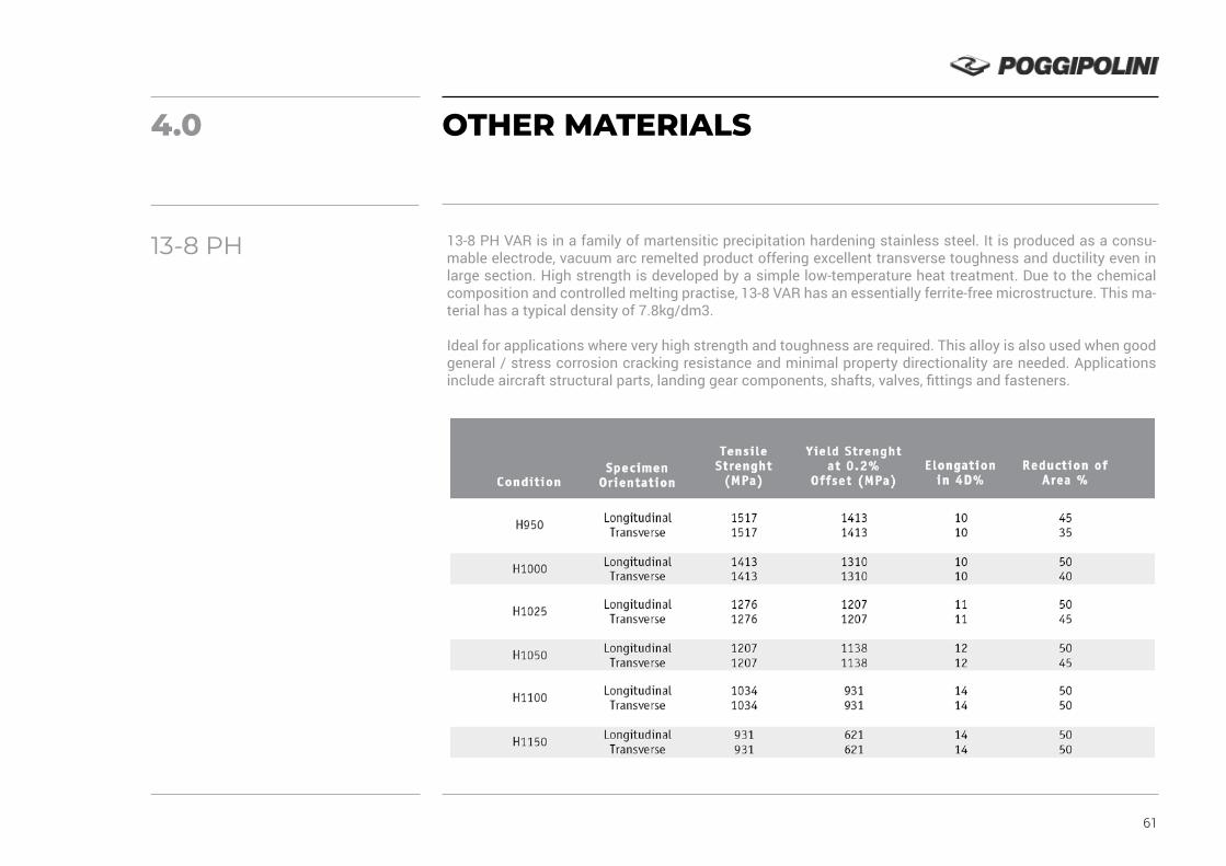
61
4.0 OTHER MATERIALS
13-8 PH VAR is in a family of martensitic precipitation hardening stainless steel. It is produced as a consu-mable electrode, vacuum arc remelted product offering excellent transverse toughness and ductility even in large section. High strength is developed by a simple low-temperature heat treatment. Due to the chemical composition and controlled melting practise, 13-8 VAR has an essentially ferrite-free microstructure. This ma-terial has a typical density of 7.8kg/dm3.
Ideal for applications where very high strength and toughness are required. This alloy is also used when good general / stress corrosion cracking resistance and minimal property directionality are needed. Applications include aircraft structural parts, landing gear components, shafts, valves, fittings and fasteners.
13-8 PH

62
17-4 PH is in a family of martensitic precipitation hardening stainless steel; it contains 4% copper and may be hardened by a single low-temperature precipitation hardening heat treatment, producing excellent mechanical properties at a high strength level.
It has a tipical density of 7.75 kg/dm3 and can be magnetised.Used where high strength and good corrosion resistance are required as well as for application requiring high fatigue strength, good resistance to galling and stress corrosion resistance.
17-4 PH
Cr 17.5 % Ni
5 %Cu
5 %Mn 1 %
Si1 %
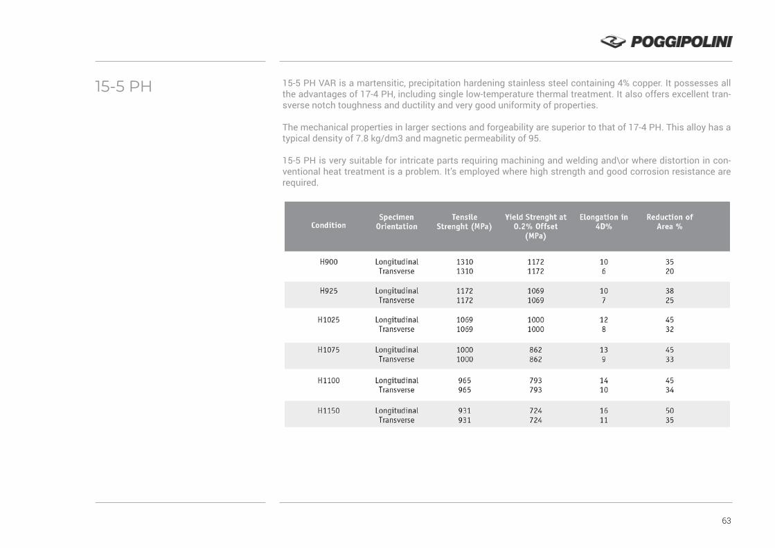
63
15-5 PH VAR is a martensitic, precipitation hardening stainless steel containing 4% copper. It possesses all the advantages of 17-4 PH, including single low-temperature thermal treatment. It also offers excellent tran-sverse notch toughness and ductility and very good uniformity of properties.
The mechanical properties in larger sections and forgeability are superior to that of 17-4 PH. This alloy has a typical density of 7.8 kg/dm3 and magnetic permeability of 95.
15-5 PH is very suitable for intricate parts requiring machining and welding and\or where distortion in con-ventional heat treatment is a problem. It’s employed where high strength and good corrosion resistance are required.
15-5 PH
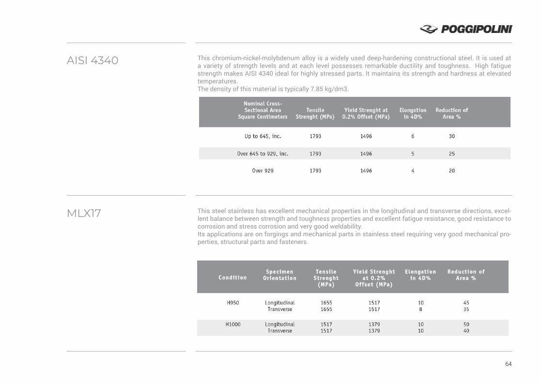
64
This chromium-nickel-molybdenum alloy is a widely used deep-hardening constructional steel. It is used at a variety of strength levels and at each level possesses remarkable ductility and toughness. High fatigue strength makes AISI 4340 ideal for highly stressed parts. It maintains its strength and hardness at elevated temperatures.The density of this material is typically 7.85 kg/dm3.
This steel stainless has excellent mechanical properties in the longitudinal and transverse directions, excel-lent balance between strength and toughness properties and excellent fatigue resistance, good resistance to corrosion and stress corrosion and very good weldability.Its applications are on forgings and mechanical parts in stainless steel requiring very good mechanical pro-perties, structural parts and fasteners.
AISI 4340
MLX17

65
Alloy 718 is a precipitation hardenable nickel-based alloy designed to display exceptionally high yield, tensile and creep-rupture properties at temperatures up to 1300°F. This alloy has excellent weldability when compared to the nickel-base superalloys hardened by aluminum and titanium. This alloy has been used for jet engine and high-speed airframe parts such as wheels, buckets, spacers, and high temperature bolts and fasteners.
AerMet 100 (UNS K92580) is an alloy that has been designed to have properties of excellent hardness and strength combined with exceptional ductility and toughness. AM 100 is used in applications that require high fracture toughness and excellent resistance to stress corrosion cracking and fatigue. AerMet® 100 is con-sidered as a candidate for use in applications such as Armour, Fasteners, Landing Gear, Jet Engine Shafts, Structural Members, Drive Shafts, Structural Tubing.
INCONEL 718
AERMET 100
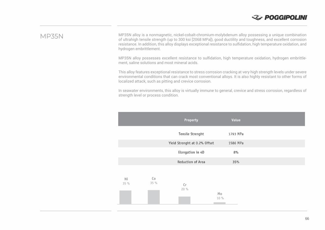
66
MP35N alloy is a nonmagnetic, nickel-cobalt-chromium-molybdenum alloy possessing a unique combination of ultrahigh tensile strength (up to 300 ksi [2068 MPa]), good ductility and toughness, and excellent corrosion resistance. In addition, this alloy displays exceptional resistance to sulfidation, high temperature oxidation, and hydrogen embrittlement.
MP35N alloy possesses excellent resistance to sulfidation, high temperature oxidation, hydrogen embrittle-ment, saline solutions and most mineral acids.
This alloy features exceptional resistance to stress corrosion cracking at very high strength levels under severe environmental conditions that can crack most conventional alloys. It is also highly resistant to other forms of localized attack, such as pitting and crevice corrosion.
In seawater environments, this alloy is virtually immune to general, crevice and stress corrosion, regardless of strength level or process condition.
MP35N
Ni 35 %
Co35 % Cr
20 %Mo
10 %
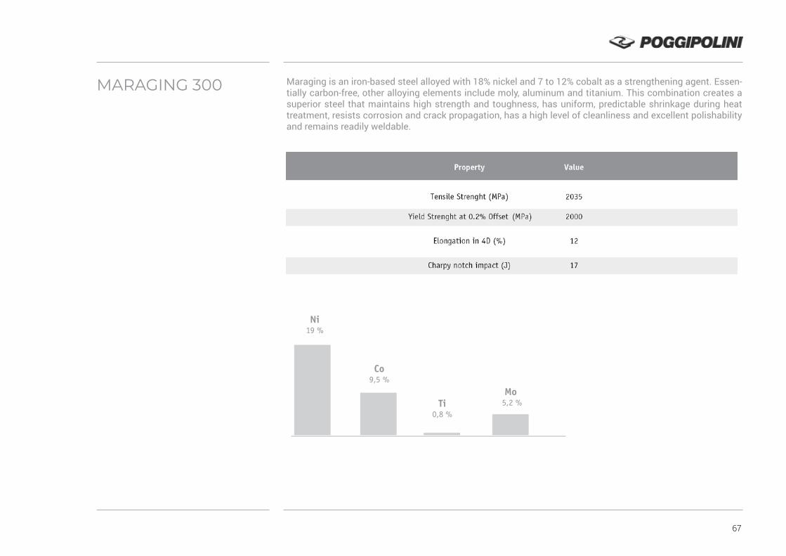
67
Maraging is an iron-based steel alloyed with 18% nickel and 7 to 12% cobalt as a strengthening agent. Essen-tially carbon-free, other alloying elements include moly, aluminum and titanium. This combination creates a superior steel that maintains high strength and toughness, has uniform, predictable shrinkage during heat treatment, resists corrosion and crack propagation, has a high level of cleanliness and excellent polishability and remains readily weldable.
MARAGING 300
Ni 19 %
Co9,5 %
Ti0,8 %
Mo 5,2 %
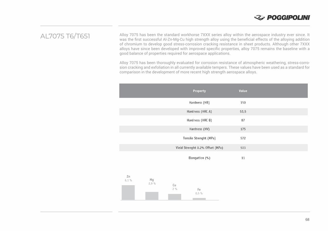
68
Alloy 7075 has been the standard workhorse 7XXX series alloy within the aerospace industry ever since. It was the first successful Al-Zn-Mg-Cu high strength alloy using the beneficial effects of the alloying addition of chromium to develop good stress-corrosion cracking resistance in sheet products. Although other 7XXX alloys have since been developed with improved specific properties, alloy 7075 remains the baseline with a good balance of properties required for aerospace applications.
Alloy 7075 has been thoroughly evaluated for corrosion resistance of atmospheric weathering, stress-corro-sion cracking and exfoliation in all currently available tempers. These values have been used as a standard for comparison in the development of more recent high strength aerospace alloys.
AL7075 T6/T651
Zn 6,1 % Mg
2,9 % Cu 2 % Fe
0,5 %
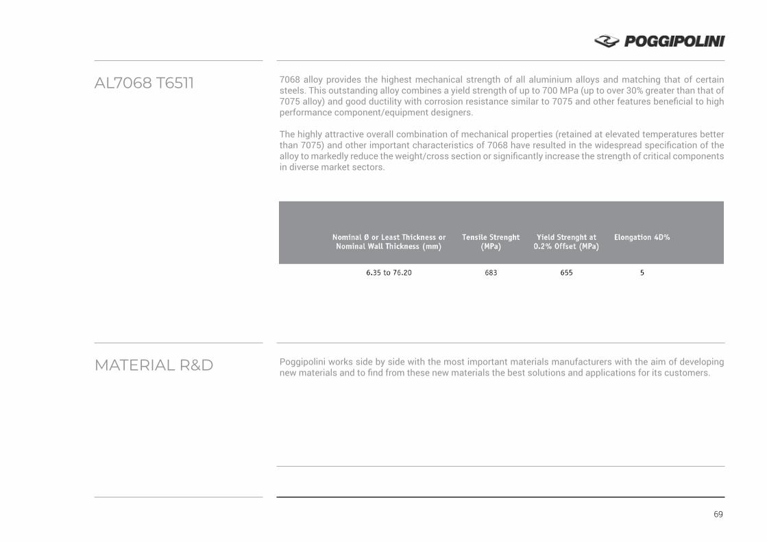
69
7068 alloy provides the highest mechanical strength of all aluminium alloys and matching that of certain steels. This outstanding alloy combines a yield strength of up to 700 MPa (up to over 30% greater than that of 7075 alloy) and good ductility with corrosion resistance similar to 7075 and other features beneficial to high performance component/equipment designers.
The highly attractive overall combination of mechanical properties (retained at elevated temperatures better than 7075) and other important characteristics of 7068 have resulted in the widespread specification of the alloy to markedly reduce the weight/cross section or significantly increase the strength of critical components in diverse market sectors.
Poggipolini works side by side with the most important materials manufacturers with the aim of developing new materials and to find from these new materials the best solutions and applications for its customers.
AL7068 T6511
MATERIAL R&D

70
5.0
HOT HEAD FORGING
MANUFACTURING
PROCESSES
Poggipolini controls in house the entire manufacturing process, from Designing to the final NDT special processes. In the following pages we present in detail each process.
Poggipolini is expert and specialist on hot head forging. Forging is a metal forming process that involves ap-plying compressive forces to a work piece to deform it, and create a desired geometric change to the material. The forging process is very important in industrial metal manufacture, particularly in the extensive iron and steel manufacturing industry. A steel forge is often a source of great output and productivity.
Work stock is put in to the forge. It may be rolled, it may also come directly from cast ingots or continuous castings. The forge will then manufacture steel forgings of desired geometry and specific material properties. These material properties are often greatly improved.
Metal forging is known to produce some of the strongest manufactured parts compared to other metal ma-nufacturing processes and obviously, is not just limited to iron and steel forging, but to other metals as well. Different types of metals will have a different factors involved when forging them. Some will be easier to forge than others. Various tests are described later to determine forging process factors for different materials. Aluminum, magnesium, copper, titanium, and nickel alloys are also commonly forged metals.
Ordinarily, head parts are cold processed by using header or press, but in case of bad plastic processability, material such as Titanium-alloy and heat resisting steel head parts are processed by hot forging. In order to control part processing, fibre flow at head parts is checked usually.

71
HEAD TO SHANK FILLET
THREAD ROLLING
Almost all the bolts rolled after head treatment will break down at the head part due to tension or tension fatigue test. In order to make the strength of head parts and thread parts balance, the strength of head parts is increased. To realize above purpose, by cold processing under head fillet surface roughness is improved by vanishing effect. As a result of this processing residual compression stress is given and fatigue strength of the head part is increased.
Thread rolling is a metal rolling process used extensively in manufacturing industry to produce screws, bolts and other fasteners. A common thread rolling process, used in industry to manufacture threaded parts, invol-ves forming the threads into the metal of a blank by a pressing and rolling action between two die. The die sur-faces hold the shape and the force of the action forms the threads into the material. A similar metal forming process has been developed for the production of gears.
Thread rolling, in modern manufacturing, has an extremely high productivity rate, significantly higher than producing threaded parts by machining. Machining is the alternative method to industrial manufacturing of threaded parts. Producing threads by this method has several other benefits over machining. Forming will harden the metal through cold working, does not waste material by cutting, and produces a favorable grain structure to strengthen the part with respect to its function.
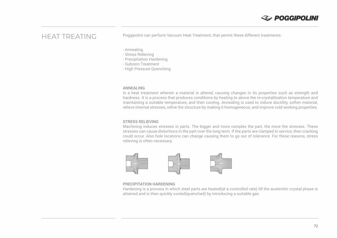
72
HEAT TREATING Poggipolini can perform Vacuum Heat Treatment, that permit these different treatments:
- Annealing- Stress Relieving- Precipitation Hardening- Subzero Treatment- High Pressure Quenching
ANNEALING Is a heat treatment wherein a material is altered, causing changes in its properties such as strength and hardness. It is a process that produces conditions by heating to above the re-crystallization temperature and maintaining a suitable temperature, and then cooling. Annealing is used to induce ductility, soften material, relieve internal stresses, refine the structure by making it homogeneous, and improve cold working properties.
STRESS RELIEVING Machining induces stresses in parts. The bigger and more complex the part, the more the stresses. These stresses can cause distortions in the part over the long term. If the parts are clamped in service, then cracking could occur. Also hole locations can change causing them to go out of tolerance. For these reasons, stress relieving is often necessary.
PRECIPITATION HARDENINGHardening is a process in which steel parts are heated(at a controlled rate) till the austenitic crystal phase is attained and is then quickly cooled(quenched) by introducing a suitable gas.

73
SUBZERO TREATMENTCryogenic hardening is a cryogenic treatment process where the material is cooled to approximately −185 °C (−301 °F), usually using liquid nitrogen. It can have a profound effect on the mechanical properties of certain steels, provided their composition and prior heat treatment are such that they retain some austenite at room temperature. It is designed to increase the amount of martensite in the steel’s crystal structure, increasing its strength and hardness, sometimes at the cost of toughness.
HIGH PRESSURE QUENCHINGFor many years now, gas quenching has been the preferred process in the heat treatment of high-speed steels and hot and cold working tool steels.
With the development of separate gas quenching chambers, it is often possible to replace oil quenching with high-pressure gas quenching using nitrogen or helium for heat treating case hardening steels or other low alloyed materials.
The success of this dry quenching technology is based on its environmental and commercial efficiency. Quen-ching gases such as nitrogen or helium are absolutely inert and without any ecological risk. They leave no re-sidues on the workpieces or in the hardening furnaces. Therefore, investments in equipment such as washing machines or fire monitoring systems are redundant. This, in turn, reduces operating costs for hardening. When helium is used as a quenching gas, appropriate recycling systems for unlimited repeated use of the helium are available.
THE ADVANTAGES OF PROCESS ARE:
- Reduction of hardening distortion and/or variation of distortion- Quenching intensity adjustable by control of gas pressure and gas velocity- Process flexibility- Clean, non-toxic working conditions- Integration into manufacturing lines- Reproducible quenching result- Clean and dry parts, no washing- Simple process control
74
5.1 COATINGS
PASSIVATION The passivation process returns the stainless steel or other metals back to its original specifications by remo-ving unwanted debris and oils from the surface and then submerging the part into a passivating bath. When a part is machined, various particles can permeate the surface of the base metal, weakening it’s resistance to corrosion and making the part more susceptible to environmental factors. Debris, dirt and other particles and residue such as free iron, grease and machining oils all affect the strength of the natural surface and can become embedded in the surface during the machining process. These often go unseen to the human eye and are often the cause of the deterioration.
As stated above, “passive” is defined as being less affected by environmental factors. The process improves and purifies the surface of the part. The restored surface acts like a protective coating to environmental factors such as air, water and other extreme environments. It is important to note that passivation does not change the outward appearance of the base metal.
The passivation of stainless steel is a process performed to make a surface passive, i.e., a surface film is created that causes the surface to lose its chemical reactivity. Stainless steel is already known as being corrosion-resistant, however the passivation process further strengthens its’ natural coating by improving the exterior surface of the overall part. Stainless steel passivation unipotentializes the stainless steel with the oxygen absorbed by the metal surface, creating a monomolecular oxide film. Passivation can result in the very much-desired low corrosion rate of the metal. Passivation is also accomplished by stainless steel electropolishing.
ADVANTAGES OF PASSIVATION ARE:
- Improved Corrosion Resistance- Uniform, Smooth Appearance and Finish- Deburring (Polished Surface)- Cleanliness- Improved and Extended Life of Product

75
ANODISING Anodising is an electrochemical process that converts the metal surface into a decorative, durable, corro-sion-resistant, anodic oxide finish. Aluminum is ideally suited to anodising, although other nonferrous metals, such as magnesium and titanium, also can be anodised.The anodic oxide structure originates from the material substrate and is composed entirely of material oxide. This material oxide is not applied to the surface like paint or plating, but is fully integrated with the underlying material substrate, so it cannot chip or peel. It has a highly ordered, porous structure that allows for secondary processes such as coloring and sealing.
Anodising is accomplished by immersing the material into an acid electrolyte bath and passing an electric current through the medium. A cathode is mounted on the inside of the anodising tank; the material acts as an anode, so that oxygen ions are released from the electrolyte to combine with the material atoms at the surface of the part being anodised. Anodising is, therefore, a matter of highly controlled oxidation—the enhancement of a naturally occurring phenomenon. The unique anodized finish is the only one in the metals industry that satisfies each of the factors that must be considered when selecting a high performance material finish:
DURABILITYMost anodized products have an extremely long life span and offer significant economic advantages through maintenance and operating savings. Anodizing is a reacted finish that is integrated with the underlying alumi-num for total bonding and unmatched adhesion.
COLOR STABILITYExterior anodic coatings provide good stability to ultraviolet rays, do not chip or peel, and are easily repeatable.
EASE OF MAINTENANCEScars and wear from fabrication, handling, installation, frequent surface dirt cleaning and usage are virtually non-existent. Rinsing or mild soap and water cleaning will usually restore an anodised surface to its original appearance. Mild abrasive cleaners can be used for more difficult deposits.
AESTHETICSAnodising offers a large and increasing number of gloss and color alternatives and minimizes or eliminates color variations. Unlike other finishes, anodising allows the material to maintain its metallic appearance.

76
COSTA lower initial finishing cost combines with lower maintenance costs for greater long-term value.
HEALTH AND SAFETYAnodising is a safe process that is not harmful to human health. An anodised finish is chemically stable, will not decompose, is non-toxic, and is heat-resistant to the melting point of material.Since the anodising process is a reinforcement of a naturally occurring oxide process, it is non-hazardous and produces no harmful or dangerous by-products.
DLC is an acronym for diamond-like carbon. DLC has some of the valuable properties of diamond, including: high hardness, low friction, resistance to wear, chemical inertness, biological compatability, electrical insula-tion, optical transparency, and smoothness. In common terms, DLC is harder than natural diamond and slicker than “Teflon.”
DLC coatings are used to impart some of the useful characteristics of diamonds onto other materials. DLC coatings can be deposited on nearly all metals, metal alloys, and also on nonmetals such as silicon, glass, ceramics, plastics, etc. DLC can be deposited at low (<200°C) substrate temperature. DLC coating has many commercial applications, including machine tools, aerospace parts, engine parts, me-dical implants, and high-end watches. Depending on the application, different formulations of DLC coatings are used.DLC coatings produce dramatic improvements in the performance and life of tools, components, and machi-nes. The hardness of DLC coatings is the foundation of their benefits. DLC in all forms is extremely hard.DLC’s hardness also makes it durable. DLC coatings protects moving parts from abrasion, maintaining smo-oth movement for much longer than uncoated parts. Engines with DLC coated parts create more horsepower and have longer lifetimes from mechanical parts that rotate, slide, and face other types of wear.
DLC coatings creater lower coefficients of friction. As friction is the enemy of almost all moving parts, lowe-ring it creates nearly universal improvement, regardless of the industry. Thus, DLC is found in engines, tools, the machining of cast and wrought aluminum, plastic injection molds, pumps, machine parts, bearings, cams, and even razor blades. Reduced friction also reduces the need for lubrication, which improves efficiency wi-thin the supply chain from raw material through to the end user.
DLC
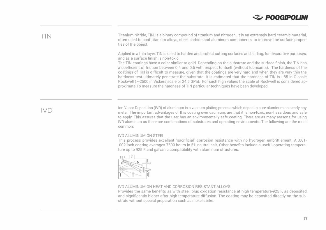
77
Titanium Nitride, TiN, is a binary compound of titanium and nitrogen. It is an extremely hard ceramic material, often used to coat titanium alloys, steel, carbide and aluminum components, to improve the surface proper-ties of the object.
Applied in a thin layer, TiN is used to harden and protect cutting surfaces and sliding, for decorative purposes, and as a surface finish is non-toxic.The TiN coatings have a color similar to gold. Depending on the substrate and the surface finish, the TiN has a coefficient of friction between 0.4 and 0.6 with respect to itself (without lubricants). The hardness of the coatings of TiN is difficult to measure, given that the coatings are very hard and when they are very thin the hardness test ultimately penetrate the substrate. It is estimated that the hardness of TiN is ~85 in C scale Rockwell ( ~2500 in Vickers scale or 24.5 GPa). For such high values the scale of Rockwell is considered ap-proximate.To measure the hardness of TiN particular techniques have been developed.
Ion Vapor Deposition (IVD) of aluminum is a vacuum plating process which deposits pure aluminum on nearly any metal. The important advantages of this coating over cadmium, are that it is non-toxic, non-hazardous and safe to apply. This assures that the user has an environmentally safe coating. There are as many reasons for using IVD aluminum as there are combinations of substrates and operating environments. The following are the most common:
IVD ALUMINUM ON STEElThis process provides excellent “sacrificial” corrosion resistance with no hydrogen embrittlement. A .001-.002-inch coating averages 7500 hours in 5% neutral salt. Other benefits include a useful operating tempera-ture up to 925 F and galvanic compatibility with aluminum structures.
IVD ALUMINUM ON HEAT AND CORROSION RESISTANT ALLOYSProvides the same benefits as with steel, plus oxidation resistance at high temperature-925 F, as deposited and significantly higher after high-temperature diffusion. The coating may be deposited directly on the sub-strate without special preparation such as nickel strike.
TIN
IVD

78
IVD ALUMINUM ON TITANIUMProvides the same benefits as with steel, plus the coating can be anodised or hard anodised to improve the wear-resistance, low absorptance-high emissivity, dielectric, color and all other properties of anodic coatings on aluminum. The coating retards titanium combustion. And it permits painting and adhesive bonding using the same techniques as with aluminum.
IVD ALUMINUM ON ALUMINUMAdds corrosion resistance to high strength aluminum alloys without sacrificing fatigue resistance, as will occur with anodising. Allows use of casting (A-380, etc.) and microcrystalline alloys in applications normally restricted to wrought materials. Also provides corrosion resistance in applications where electrical continuity or bond is required. This eliminates “jumper” connections.
Dry lubricants or solid lubricants are materials which despite being in the solid phase, are able to reduce fri-ction between two surfaces sliding against each other without the need for a liquid oil medium.
The two main dry lubricants are graphite and molybdenum disulfide. They offer lubrication at temperatures higher than liquid and oil-based lubricants operate. Dry lubricants are often used in applications such as locks or dry lubricated bearings. Such materials can operate up to 350 °C (662 °F) in oxidizing environments and even higher in reducing/non-oxidizing environments (molybdenum disulfide up to 1100 °C, 2012 °F). The low-friction characteristics of most dry lubricants are attributed to a layered structure at the molecular level, with weak bonding between layers. Such layers are able to slide relative to each other with minimal applied force, thus giving them their low fri-ction properties.
However, a layered crystal structure alone is not necessarily sufficient for lubrication. In fact, there are also some solids with non-lamellar structures that function well as dry lubricants in some applications. These include certain soft metals (indium, lead, silver, tin),polytetrafluroethylene, some solid oxides, rare-earth fluo-rides, and even diamond.
Limited interest has been shown in low friction properties of compacted oxide glaze layers formed at several hundred degrees Celsius in metallic sliding systems. However, practical use is still many years away due to their physically unstable nature.
TOP COAT\DRY LUBRIFICANT

79
THE FOUR MOST COMMONLY USED SOLID LUBRICANTS ARE:
GRAPHITE: used in air compressors, food industry, railway track joints, open gear, ball bearings, machine-shop works, etc. It is also very common for lubricating locks, since a liquid lubricant allows particles to get stuck in the lock, worsening the problem.
MOLYBDENUM DISULFIDE (MOS2): used in CV joints and space vehicles. Will lubricate in a vacuum.
HEXAGONAL BORON NITRIDE: used in space vehicles. Also called “white graphite.”
TUNGSTEN DISULFIDE: similar usage as molybdenum disulfide, but due to the high cost, only found in some dry lubricated bearings.
Graphite and molybdenum disulfide are the predominant materials used as dry lubricants.
Zinc Aluminium flakes coatings are non-electrolytically applied coatings, which provide good protection against corrosion. These coatings consist of a mixture of zinc and aluminium flakes, which are bonded to-gether by an inorganic matrix.
THERE ARE THREE GROUPS OF ZINC FLAKE COATINGS:
1. Zinc flake coatings containing Cr(VI) (hexavalent chromium): surfaces containing Cr(VI) provide greater anti-corrosion protection with a thinner coating, but Cr(VI) is carcinogenic and poses a potential risk to the environment. New European decrees prohibit the use of surfaces containing Cr(VI).
2. Solvent based Cr(VI)-free zinc flake coatings.
3. Water based Cr(VI)-free zinc flake coatings. Cr(VI)-free coatings are more environmentally friendly than surfaces with a Cr(VI) content. No zinc flake coatings used in the automotive industry nowadays contain this substance. Various manufactures, such as car companies and their suppliers, have produced their own speci-fications and supply rules in order to define the requirements for these coating systems.
ZINC ALUMINIUM FLAKES COATINGS

80

VISION
OUR VISION IS TO BECOME YOUR ADDED VALUE, YOUR SOLUTIONS PROVIDER.
We are driven by a continuous pursuit of excellence on every single aspect from innovativemanufacturing systems to the latest materials, coatings and treatments.
Our certifications shows our level of competence and quality.
Our passion shows our commitment to the best and beyond.

AER-
Ed. 0
1/20
Poggipolini S.r.l.Via Emilia Levante, 262 - 40068 S. Lazzaro di Savena (BO) - ITALY T. +39 051 6256090 F. +39 051 6257084 E. [email protected]
WWW.POGGIPOLINI.IT


