23

2
Special Provisions 14 November 2019_Cover-2.docx engineersaustralia.org.au
DISCLAIMER
The information in this publication is provided as guidelines that may be used by suitably qualified practitioners to assist in site investigations and footing and foundation design situations where information on the subject matter cannot otherwise be obtained from the normative and informative sections of AS2870. The guidelines do not constitute professional advice. The Footings Group, SA Division has used reasonable care and a best endeavours approach to ensure that material presented in the guidelines was accurate at the time of publishing. However:
• Engineers Australia does not warrant the accuracy, content, completeness, or suitability of
the information in the guidelines. • Any reliance made by a practitioner on the material shall be at the practitioner’s own risk
after exercising their own or independent engineering judgement. Engineers Australia will not be liable for any claims or damages whatsoever resulting from use of or reliance on information on information in this publication. © Engineers Australia 2019 ISBN: 978-1-925627-61-9
3
Special Provisions 14 November 2019_Cover-2.docx engineersaustralia.org.au
CONTENTS 1. GENERAL 1.1 USE 1.2 APPLICATION 1.3 REFERENCE DOCUMENTS 1.4 STATUTORY REQUIREMENTS 2. GEOTECHNICAL 2.1 SITE INVESTIGATION 2.2 SOIL DESCRIPTIONS 2.3 GROUND MOVEMENT COMPUTATION (ys) 2.4 GROUND MOVEMENT COMPUTATION FOR TREE DRYING EFFECTS (yt) 2.5 GROUND MOVEMENT COMPUTATIONS FOR TREE REMOVAL 2.6 SOIL MOVEMENT 2.7 PROBLEM SITES 3. BUILDING CONSTRUCTION 3.1 SPECIAL CONSTRUCTION 3.2 ARTICULATION 4. FOOTING DESIGN 4.1 LOADS 4.2 DESIGN PROCEDURES FOR STIFFENED RAFT, WAFFLE RAFT AND STRIP FOOTING
SYSTEMS 4.3 BEAM DESIGN 4.4 WAREHOUSE BUILDING 4.5 MOUNT GAMBlER STONE FOOTINGS 4.6 TRANSPORTABLE BUILDINGS 5. FOOTING DETAILS FOR STIFFENED RAFT, WAFFLE RAFT AND STRIP FOOTING
SYSTEMS 5.1 COVER 5.2 SUSPENDED CONCRETE FLOORS IN ONE STOREY CONSTRUCTION 5.3 CONCRETE FOOTINGS WITHIN THE PLANNING SA CORROSION ZONE 5.4 POLISHED CONCRETE 5.5 CELLARS – WATER PROOFING AND LIMITATIONS 5.6 SPACING AND SET OUT OF STRIP FOOTINGS 5.7 MAXIMUM BEAM SPACING FOR E SITES 6. FOOTING CONSTRUCTION 6.1 OVERSIZE FOOTINGS 6.2 FOOTINGS AND SLABS
4
Special Provisions 14 November 2019_Cover-2.docx engineersaustralia.org.au
7. SITE WORKS 7.1 EXCAVATION 7.2 FLEXIBLE PVC WATER SERVICE CONNECTIONS 7.3 DRAINAGE AND PLUMBING REQUIREMENTS FOR M, H1, H2 & E SITES 8. FOOTING REPORTS 8.1 GENERAL 8.2 PRELIMINARY SITE SOIL ASSESSMENT REPORT 8.3 FOOTING CONSTRUCTION REPORT 9. COMMENTARY 10. COMMENTARY ON AS2870-2011 TREE DESIGN RECOMMENDATIONS
5
Special Provisions 14 November 2019_Cover-2.docx engineersaustralia.org.au
1. GENERAL
1.1 USE
The information in this publication is provided as guidelines that may be used by suitably qualified practitioners to assist in site investigations and footing and foundation design situations where information on the subject matter cannot otherwise be obtained from the normative and informative sections of AS2870. It is not to be used in place of professional advice.
1.2 APPLICATION
This document is intended to apply as a supplement to AS2870-2011 and comments on some clauses in AS2870-2011.
This document sets out additional procedures for good practice current at the date of issue, for:
1. The investigation of the soil profile and site classification 2. The design of footings 3. The construction of footings 4. Building construction and site-works relevant to the footing design 5. Drainage design & sewer services relevant to the footing design 6. Documentation to be provided with footing designs
This document has an emphasis on the design of stiffened footings on expansive soils and does not cover design for conditions such as soft clays, dispersive soils, sinkholes, Iandslip areas, mining subsidence, organic soils, earthquake effects or the detailed design requirements for piled footings. Reference to collapsible soils is included.
1.3 REFERENCE DOCUMENTS
AS2870-2011 provides a list of reference publications, which should be referred to
in the preparation of all documentation. In addition, the following information (including soil and geology maps) may apply to
the Adelaide Metropolitan area.
1. Sheard, M. J. and Bowman, G. M. (1996). Soils, Stratigraphy and Engineering Geology of Near Surface Materials of the Adelaide Plains. Dept. Mines and Energy, Report Book 94/9, Volumes 1, 2 and 3, Adelaide (available on CD from PIRSA).
2. Taylor, J. K., Thomson, B. P. and Shepherd, R. G. (1974). The Soils and Geology of the Adelaide Area. Dept. Mines, Geological Survey SA, Bulletin 46.
3. Taylor, J. K. (1976). Soils of the Southern Adelaide Region. Dept. Mines, Geological Survey SA.
4. Geological Survey of S.A., “Adelaide”, Sheet S1 54-9, 1969. 5. Geological Survey of S.A., “Barker”, Sheet 1 54-13, 1962. 6. Bulletin 51, “Engineering Geology of the Adelaide City Area”, 1982. 7. City of Happy Valley Soil Map.

6
Special Provisions 14 November 2019_Cover-2.docx engineersaustralia.org.au
8. Footings and Foundations for Small Buildings in Arid Climates with special Reference to South Australia, The Institution of Engineers Australia, June 1979, SA Division (not available for purchase)
9. Mitchell, P. W. (2007) The continuing problems associated with expansive and collapsing soils. Keynote address to 10th Australia-New Zealand Conference on Geomechanics, Brisbane, October.
These references should be used to assist in the classification of sites, wherever
practical.
1.4 STATUTORY REQUIREMENTS
Notwithstanding anything contained in this publication, all construction shall comply with the requirements of all relevant statutory authorities.
2. GEOTECHNICAL
2.1 SITE INVESTIGATION
The investigation program should suit the particular pattern and nature of the construction.
The minimum number of exploration positions is defined by AS2870-2011 section
2.4.4. As a general guide, for large building areas, such as multiple dwellings in a land division, the minimum number of exploration positions should be determined in accordance with the following if soil profiling indicates uniform soil conditions. Additional exploration holes are required for areas known to have variations in soil or if variations are encountered during the investigation. The engineer/site classifier needs to be informed of any variations observed during exploration on the site, such that the engineer is satisfied that the investigation carried out is adequate for a site classification for the proposed building work.
Covered Area (m2) Minimum number of bores 600-1200................................................4 1201-2000................................................5 >2000................................................5 + 1 per 1000 m2 or part thereof
2.2 SOIL DESCRIPTIONS
Soil descriptions and estimates of soil shrinkage index and soil strength may be derived from the visual-tactile identification approach in accordance with AS1726. The accuracy of logging procedures should be evaluated periodically. A suitably qualified and experienced person shall check the soil property identification against property testing on reactive soils at a period of not longer than 6 months and at least once in every 50 sites personally classified (refer 2.3.4 (iii) of AS2870-2011). The laboratory tests and data should be saved and catalogued with the following information recorded:
a) Date of soil sampling and date of laboratory test b) Place of sampling c) Depth of sample tested
7
Special Provisions 14 November 2019_Cover-2.docx engineersaustralia.org.au
d) Description of the soil material tested e) Soil laboratory test carried out e.g., shrink-swell.
2.3 GROUND MOVEMENT COMPUTATION (ys)
In the Adelaide area, if no suction tests are carried out, the value of ys may be determined by assuming a differential suction of ru = 1.2 (e.g., 3.3 pF min. to 4.5 pF max.) at the surface for normal sites, varying linearly to 3.9 pF to a depth of Hs = 4.0 m.
For soil profiles which consist of clean sand or gravel over reactive clay,
consideration should be given to greater design suction change at the interface due to the potential ingress of moisture.
The Ips of a soil between a depth of 3.0 m and 4.0 m may be assumed to be that of
the soil material encountered at the base of a 3.0 m, except that where logging of the soil, experience or published data indicates a transition to a more reactive clay, then a value of Ips compatible with the more reactive clay should be assumed below 3.0 m.
If the maximum drying depth of soil (Ht) is 4.5m due to tree group drying effects, soil
sampling should be drilled or excavated to a minimum depth of 3.5m, unless the soil profile is known below the 3m depth.
Where a permanent water table is encountered, the depth Hs may be varied in
accordance with AS2870-2011 Section 2.3.3 and figure 2.1. A perched watertable shall not be considered as a permanent watertable.
2.4 GROUND MOVEMENT COMPUTATION FOR TREE DRYING EFFECTS yt
In accordance with the recommendations of AS2870-2011, where there are trees which may affect the design ground movement, the site shall be classified as P.
AS2870-2011, Appendix H: The additional effect of tree drying or removal of tree/s on the design suction change profile shall be determined in accordance with AS2870-2011 the Guide to Design of Footings for Trees, which is Informative in the code. This replaces the “Special Provisions for the Design of Residential Slabs and Footings for South Australian Conditions” method of computation last published May 2008.
2.5 GROUND MOVEMENT COMPUTATIONS FOR TREE REMOVAL In accordance with AS2870-2011, where tree removal or death of a tree is anticipated in the vicinity of a proposed building, footings should be designed to allow for the subsequent rebound of the soil in accordance with the design procedure provided in Appendix H. This design procedure shall be carried out where a tree has been removed or died within a 5-year period prior to the construction of the building or if tree removal has been specified by the footing designer.
8
Special Provisions 14 November 2019_Cover-2.docx engineersaustralia.org.au
2.6 SOIL MOVEMENT
The value of ym may be varied for edge heave, provided soil suction values are measured at the time of construction and the variation in the value of ym is based on consideration of potential suction variations between the actual and lower bound values.
2.7 PROBLEM SITES
Collapsing Soils Collapsing soils appear strong when dry but lose considerable strength on wetting. As stated in AS2870-2011 clause C2.1.3, it is important for collapsing soils to be correctly identified. Characteristically, collapsing soils are of low density and low plasticity. Typically collapsing soils in South Australia are aeolian in origin, such as the Brown Solonized soils near the Eden Fault in Adelaide, or the inland and coastal dune sands, such as those found in Port Augusta, northern Yorke Peninsula, the Murray Mallee, the Riverland, and many other areas. Other collapsing soils can comprise those formed by hillwash, such as the Pooraka Formation soils, or biotic soils, formed by the activities of burrowing animals, earthworms, or decayed roots. Sites with collapsing soils are to be designated as ‘P’ sites and will require individual design consideration. Footings constructed on these soils can be adversely affected by water inundation, so that site drainage and the flexibility of water service connections are of paramount importance. The modification of collapsing soils can be achieved by controlled pre-wetting and loading with compaction equipment. If prewetting is specified in the design, consideration must be given to the depth of improvement and the stability of neighbouring structures. The normal methods currently in use for designing a footing system on a swelling soil profile do not readily translate to a collapsing soil profile and there are no generally accepted design procedures for designing shallow stiffened footings on deep collapsing soils. Nevertheless, based on observations of distorted structures constructed on the collapsing soils located in the Riverland of South Australia (Reference 9 of Section 1.3), it would be unwise to design a footing on these soils which has a stiffness and bending moment capacity less than that corresponding to a Class H2-D site classification. Experience has shown that satisfactory performance with footing designs on collapsing soils has been achieved by using either the Walsh method or the Mitchell method and designing for an “equivalent” ys = 75 mm, with adequate surface water drainage and flexible plumbing connections. Another approach which more closely reflects the observed behaviour of collapsing soils is to determine the negative bending moments and deflections calculated for an unsupported, fixed-ended cantilever edge distance of 3.0 m. This condition also applies at the corners of a gridded footing system. The footing design then follows the procedures of Clause 4.4 of AS 2870-2011, with the span parameter, L, in Table 4.1 being taken as the full length of the footing, rather than 3.0 m. The footing system is proportioned to resist positive and negative bending moments of approximately the same magnitude.

9
Special Provisions 14 November 2019_Cover-2.docx engineersaustralia.org.au
Filled Sites The industry trend is to smaller allotments and in many cases boundary to boundary construction. Settlement, differential settlements, and possible tilting of buildings is hence far more critical. Deep filled sites will settle over time, regardless of the degree of engineering control. Engineering control of moisture content and density is needed to limit the settlement that may occur. Differential movements are likely to occur at the edge of the fill and the between areas of fill of different depth. The footings of buildings must be provided with adequate structural capacity to accommodate the estimated differential deflections and the superstructure should be appropriately articulated. Deep filled sites shall be treated as uncontrolled fill sites. Alternatively, a deep filled site may be considered to be a controlled fill site if a certificate is provided by the Superintendent of the earthworks, or a Geotechnical Engineer which states that the earthworks have been carried out in accordance with an appropriate specification prepared by a Qualified Geotechnical Engineer and that the fill is suitable for residential construction in accordance with AS2870. In providing such certification, the Certifier shall take account of the impact of future settlements and differential settlements that may occur (including Long Term Creep, Settlement, and potential Hydroconsolidation Settlement). As a minimum, the certification shall include:
• Contour Plan of maximum excavation. • Contour Plan of finished surface levels. • Heat Map of depth of compacted fill. • Summary of fill depths across the particular allotment. • Maximum depth of fill and location (as applicable). • Estimated maximum settlement. • Estimated differential settlements; and • Certification that the site preparation is in accordance with the requirements of the
Specification and AS3798-2007
Note: The issues of differential settlements at significant changes in fill depth and excavation boundaries can apply for fill depths as low as 3 to 5 metres.
This information provides an adequate description of the “man made ground” for consumer /purchasers and the fill settlements a footing designer will need to design for. If this information is not provided, the normal site investigation practices for a natural clay site will not be relevant for deep fill sites. Much deeper geotechnical investigation is required, and good quality samples or field penetration tests (or both) are needed to assess the compressibility of the soil throughout the filled soil profile. Site Classifiers and Footings Designers need to be cognisant of these settlements in addition to potential reactive clay soil movements. Recommendations and restrictions for design and support of services (flexible connections), pavement transitions, as well as footing design and building articulation and materials, are to be included in the Footing Construction Report.
10
Special Provisions 14 November 2019_Cover-2.docx engineersaustralia.org.au
On-site Water Disposal Effluent disposal or in-ground stormwater detention systems located close to houses require consideration of classification of the site to Class P.
3. BUILDING CONSTRUCTION
3.1 SPECIAL CONSTRUCTION
Buildings with single leaf external masonry may be taken as equivalent to masonry veneer, provided there are no internal masonry walls.
Detailing of joints and articulation of Aerated Concrete Construction, panels or
walls need to be in accordance with the manufacturer’s recommendations in the specifications provided by the manufacturer of the walling material.
Construction with Concrete Tilt Up walling with joints between the panels may be
considered as articulated masonry veneer.
Light weight construction such as fibreglass panels and “insulation” panels, may be classified as equivalent construction to masonry veneer if the walls are not articulated.
3.2 ARTICULATION
Articulation shall comply with the requirements of TN 61 and AS4773.2 except as noted below.
The initial joint widths shall be limited to 10 mm by limiting the joint spacing as set out in TN61.
The spacing of articulation joints should be reduced for two storey dwellings if the
wall is structurally continuous over the height of the building or change the deflection criteria.
The spacing of articulation joints in rendered external walls should be reduced or
change the deflection criteria.
Walls with joints further apart than 10 m, shall be considered as non-articulated. Allowable deflections and deflection ratios for joint spacings less than 10 m and equal to or greater than 6 m, may be determined by linear interpolation.
For example: a cavity masonry wall,
Joint Spacing Deflection Ratio Max Deflection < 6 m 800 15 mm 8 m 1400 12.5 mm > 10 m 2000 10 mm
11
Special Provisions 14 November 2019_Cover-2.docx engineersaustralia.org.au
4. FOOTING DESIGN
4.1 LOADS
The design shall take into account the position of all loads, including footing self-weight.
These loads may be distributed into perimeter loads, centre line loads, and uniformly distributed loads. Eccentric loads may be distributed into one of the above to give the same total load static bending moment as the actual load and position.
Live loads due to domestic car parking may be the same as internal floor live loads.
Skin friction on the sides of the footing beams, within a depth of one metre below finished ground level, may be ignored. Where footings are continuously trenched more than one metre below finished ground level, the skin friction on the section below one metre may be taken as 25 kPa on each side or use two layers of minimum 0.2mm branded plastic membrane to the side faces of the beams to counter skin friction.
4.2 DESIGN PROCEDURES FOR STIFFENED RAFT, WAFFLE RAFT, AND STRIP FOOTING SYSTEMS
Beams which are common to two or more rectangles need only be designed for
the rectangle which produces the largest actions.
Footings for buildings incorporating different types of construction may be designed with different footings, (e.g., party walls or boundary walls which have different sections), depending on the various deflection ratios. Footing details should not vary over a design rectangle (except for secondary beams).
Where sections of the main roof continue beyond the external wall line e.g., carport
under the main roof, the carport footings may be designed for clad framed construction. This clause is not applicable where masonry walls form part of the carport external wall construction. Pad footings may be used on A and S sites for support of the roof.
4.3 BEAM DESIGN
Where footings are to be designed for tree effects, they shall be designed in
accordance with Appendix H of AS2870_2011.
Where footings are designed to span between piers, the footing beams shall be designed to resist the combined effects of expansive soil movements and suspended loads.
12
Special Provisions 14 November 2019_Cover-2.docx engineersaustralia.org.au
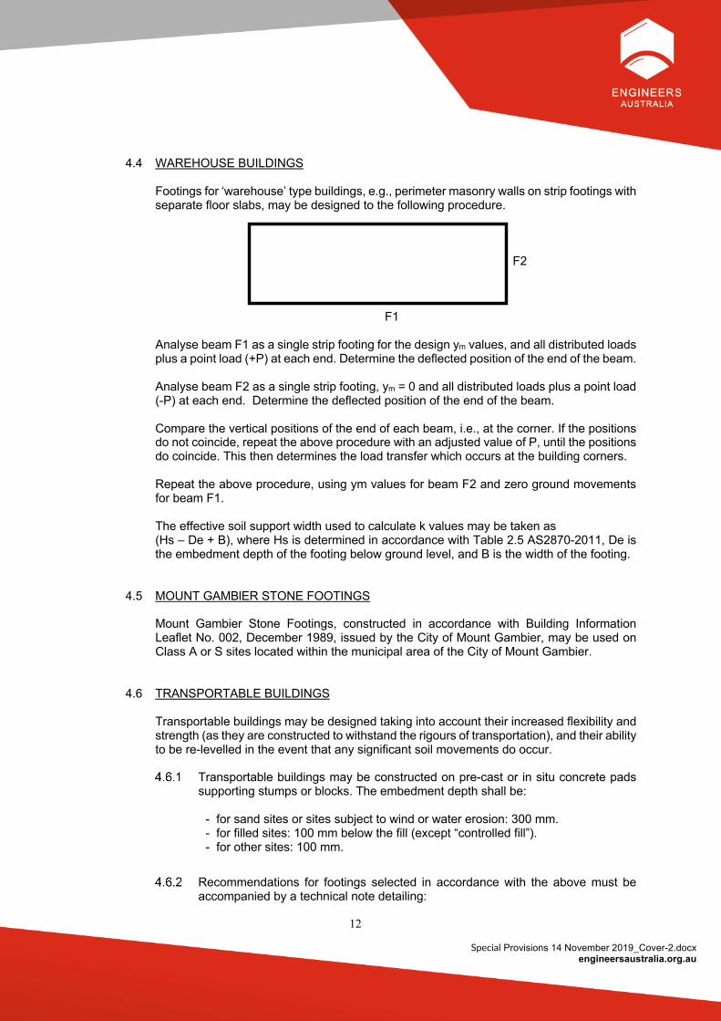
4.4 WAREHOUSE BUILDINGS
Footings for ‘warehouse’ type buildings, e.g., perimeter masonry walls on strip footings with separate floor slabs, may be designed to the following procedure.
F2
F1
Analyse beam F1 as a single strip footing for the design ym values, and all distributed loads plus a point load (+P) at each end. Determine the deflected position of the end of the beam.
Analyse beam F2 as a single strip footing, ym = 0 and all distributed loads plus a point load (-P) at each end. Determine the deflected position of the end of the beam. Compare the vertical positions of the end of each beam, i.e., at the corner. If the positions do not coincide, repeat the above procedure with an adjusted value of P, until the positions do coincide. This then determines the load transfer which occurs at the building corners. Repeat the above procedure, using ym values for beam F2 and zero ground movements for beam F1. The effective soil support width used to calculate k values may be taken as (Hs – De + B), where Hs is determined in accordance with Table 2.5 AS2870-2011, De is the embedment depth of the footing below ground level, and B is the width of the footing.
4.5 MOUNT GAMBlER STONE FOOTINGS
Mount Gambier Stone Footings, constructed in accordance with Building Information Leaflet No. 002, December 1989, issued by the City of Mount Gambier, may be used on Class A or S sites located within the municipal area of the City of Mount Gambier.
4.6 TRANSPORTABLE BUILDINGS
Transportable buildings may be designed taking into account their increased flexibility and strength (as they are constructed to withstand the rigours of transportation), and their ability to be re-levelled in the event that any significant soil movements do occur.
Transportable buildings may be constructed on pre-cast or in situ concrete pads supporting stumps or blocks. The embedment depth shall be:
- for sand sites or sites subject to wind or water erosion: 300 mm. - for filled sites: 100 mm below the fill (except “controlled fill”). - for other sites: 100 mm.
Recommendations for footings selected in accordance with the above must be accompanied by a technical note detailing:
13
Special Provisions 14 November 2019_Cover-2.docx engineersaustralia.org.au
- the basis on which their footing design has been carried out - the limitations of the design - advising that adequate access and clearance must be left under the building
for re-levelling - site management requirements that must be observed by the owner, including
regular inspections to consider if re-levelling is required. - a drainage design is recommended for surface stormwater disposal around the
perimeter of the buildings. This is to avoid localised settlement and/or heave of isolated footings due to
ponding of surface stormwater and wetting of prepared benched platforms. 5. FOOTING DETAILS FOR STIFFENED RAFT, WAFFLE RAFT AND STRIP FOOTING
SYSTEMS
5.1 COVER
The design cover to reinforcement (including ligatures) shall be as specified in AS2870-2011 Section 5.3.2(a). The permitted tolerances are ± 10 mm except that the +ve tolerance may be increased where the design strength of the section is not reduced.
5.2 SUSPENDED CONCRETE FLOORS IN ONE STOREY CONSTRUCTION Refer also to Section 3.8 AS2870-2011 The concrete floors shall be designed in accordance with engineering principles. Short span internal concrete slabs not supporting load bearing walls or columns may span up to 4 m if slabs are 125 mm thick reinforced with SL72 mesh top and SL72 mesh bottom.
5.3 CONCRETE FOOTINGS WITHIN THE PLANNING SA CORROSION ZONE As consequence of industry discussion and technical presentations during 2018, the Footings Group was requested to document a uniform industry practice. South Australia’s jurisdiction has a corrosion maps (Planning SA) with a line on it which Engineers and Builders are obliged to apply corrosion protection recommendations. AS 2870 is silent on air-borne exposure issues. On that basis most Engineers revert to AS3600’s requirements within the corrosion zone. Section 4.3.2 gives a concession that allows the concrete strength to be reduced to the next lowest grade where only one surface of the “member” is exposed provided that the concrete cover is increased by 20mm from that which would have been used. Concrete exposed to the marine environment shall be detailed as follows:
- Use 20MPa concrete on the landward side of the Planning SA corrosion line. This has been based on past adequate performance of the footings and the existence of the recommended corrosion boundary.
14
Special Provisions 14 November 2019_Cover-2.docx engineersaustralia.org.au
- Use 32MPa concrete within the corrosion boundary on the basis that the external cover to a raft footing is in practice, 50mm not 30mm (allowing us to downgrade to the next grade of concrete (32MPa) from that recommended by AS3600)
- Engineering judgement may be applied to determine whether a building is “shielded”, and as a consequence 32MPa concrete may not be required for the footings for the full distance of the corrosion zone. However, it is required that other corrosion protection requirements in the BCA be implemented for the super structure e.g., galvanised lintels etc.
- NOTE: For a raft footing, technically only the external, exposed footings need to be 32MPa. However, this would include the portion of slab associated with the external footings as well as verandas, patios, carports, and the like. As a consequence, the industry appears to use 32MPa for the whole raft footing.
5.4 POLISHED CONCRETE
Guidance for the specification of concrete for polished concrete floors is given in Cement Concrete and Aggregates Australia publications:
- Guide to Concrete Construction (T41/HB64), Cement and Concrete Association of Australia and Standards Australia, 2002; and
- Briefing 05 Polished Concrete Floors, Cement Concrete and Aggregates Australia, 2006.
Polished concrete finishes are proving a difficult issue for the building industry to manage the gap between Client expectations and an achievable polished finish outcome due variability of finish colour, texture and shrinkage cracking that will almost always occur. It is recommended that the design engineer takes measures to ensure that shrinkage cracking is minimised where a polished concrete finish is preferred. These measures may include increasing the concrete strength and increasing the amount of reinforcement provided in the slab. Despite this, shrinkage cracking will occur, and it is recommended that the Client is advised of the potential finish outcomes of a polished concrete slab and the difficulties in achieving a crack free polished concrete finish. It is suggested that notes similar to the below be added to the footing layout plan and be included in the footing construction report: “The owner must be made aware by the builder as to what the final outcome of the polished concrete process will be in terms of the finish texture, colour, staining and general appearance consistency, all considered over the life of the building. ENGINEERING BACKGROUND: Concrete is a mixture; therefore, various aspects affect the surface finish. These include the temperature at placement, the adequacy of the concrete vibration at placement, the removal of excess surface water at time of placement in conjunction with assuring the right amount of water is used at placement and the method and duration of curing. All these matter to the success of the finished polished concrete outcome. Nevertheless, cracking is unavoidable and IF A CRACK FREE SURFACE FINISH IS EXPECTED, THEN DO NOT USE POLISHED CONCRETE. Instead, use some form of expert applied Terrazzo finish atop of the structural concrete. POLISHED CONCRETE FLOOR MAINTENANCE. Concrete floors shrink and are also subject temperature and ground movement effects, all which lead to cracking. Delaying the
15
Special Provisions 14 November 2019_Cover-2.docx engineersaustralia.org.au
concrete polishing till 9 months after the concrete pour can reduce the possibility of some shrinkage cracking occurring after the polish, but there needs to be polishing revisits to repair cracks that occur later in the life of the polished concrete. Also, there can be the need to re-apply the various coatings that may have been used to seal the polished concrete surface from spills and staining. The Concreter and the Concrete Polisher must consult each other and agree upon their needs to achieve the Owner’s required concrete polish finish. If the Engineers specification for the concrete structure does not meet the Concreter’s & Polishers trade needs, then those trades each must agree on the upgrade of the concrete specification to achieve their own needs and requirements. The Engineer’s specification is a minimum structural adequacy-based specification only. It is expected that the Concreter and the polisher work together and are experts at their work. The Builder and the Owner must not proceed with the polished concrete decision until each understands and agrees upon the finished polished concrete outcome, considering appearance and future maintenance needs to deal with cracking, staining and wear over the life of the building. With the above noted input from the Builder’s Concreter and Polisher working together, it is the Builder’s responsibility to ensure that this agreement occurs.”
5.5 CELLARS – WATER PROOFING AND LIMITATIONS During 2017 and 2018 there were considerable industry issues with respect to waterproofing of “cellars” after various technical presentations it was decided that notes with respect to this should be included in the Special Provisions.
Definitions for residential construction: Cellar – Not a habitable room and for storage purposes only. Usually “water resistant” but not “waterproof” unless specifically instructed to be waterproof. Confined space – Refer definition given in WHS Regs. Chapter 1, Part 1, Section 5 Definitions Underground room, Studio or Home Theatre – A habitable space and as such shall be waterproofed and have ventilation and natural light provisions according to the requirements of the NCC vol.2. Water Resistant – Means a barrier to water intrusion but not a totally impermeable barrier in the sense of a waterproof structure so may allow some water in liquid or vapour form to intrude into the space from time to time. Waterproof – Means an impermeable barrier to water in both liquid and vapour form and no intrusion into the habitable space.
Design notes and limitations
a. Industry experience tells us that while water resistant is achievable (e.g., shotcrete cellars), the concept of achieving waterproofing has proven to be far more difficult and costly by its very nature.
b. Engineers must be transparent in carefully explaining in writing to homeowners and their appointed agents (e.g., Architects, Builders & Drafting services) exactly what the likely outcomes will be should they simply instruct you to design a cellar or underground room, perhaps to be utilized as a home theatre or for some other form
16
Special Provisions 14 November 2019_Cover-2.docx engineersaustralia.org.au
of human habitation. Noting also that habitable rooms require ventilation according to the NCC vol.2.
c. In giving owners and their agents an explanation of the different levels of risk involved in making their choice of having an underground structure designed to be water resistant versus waterproof, or vice versa, whatever selection is made your obligation as designer is to prepare a design to current industry standard that will remain fit for its intended purpose.
d. Some design issues to be considered and/or warned about are:
- Obtain from owner information in writing on the intended use of the underground space – is it only for storage (cellar) or is it a habitable room for home theatre, bedroom, office, or the like?
- If shotcrete (the cheapest & quickest construction) then as a water-resistant design owners must be warned that it may suffer from intermittent water entry in either liquid or vapour form.
- Boundary construction will require protection of adjoining owners’ assets (land and buildings) with respect to their stability along with other issues such as termite management and the giving of 28 days’ notice in writing of the impending works (Dev Act 1993 secn. 60).
- Safe excavation practices and safety in design must also be considered for all external waterproofing applications that are usually done in confined spaces.
- Have regard to ventilation and natural light provisions according to the NCC.
5.6 SPACING AND SET-OUT OF STRIP FOOTINGS
Section 3.6.2 (a) in AS2870-2011 is misleading. The wording in effect says that the 6m rule for strip footing spacing as shown in Figure 3.6 applies to only strip footings 700mm or deeper as specified in the table on Figure 3.6. This means that as an example, the following footings that have Table 3.6 footing depths less than 700mm: - • Strip Footings including for 2 storeys for Articulated Masonry Veneer on Class M-D; • Strip Footings including for 2 storeys for Articulated Full Masonry on Class M sites. • Strip Footings including for 2 storeys for Non-Articulated Full Masonry on Class A & S
sites. can have footings spaced at greater than 6m. Also, amongst other cases, an Articulated Masonry Veneer internally clad framed building on an M-D site of size 30m x 30m (square building) with 2 storey is permitted by this clause to have just an external strip footing around the perimeter of that 30m x 30m building with no internal footing grid network. It is recommended that the 6m rule be implemented for all these conditions for residential scale construction. For South Australian conditions, Section 3.6.2 (a) shall apply for all footing depths set out in “Figure 3.6 (in part) Strip Footings Systems” except for where footings are designed in accordance with Section 4.6 of these Special Provisions.
17
Special Provisions 14 November 2019_Cover-2.docx engineersaustralia.org.au
5.7 MAXIMUM BEAM SPACING FOR E SITES For South Australian conditions, the maximum beam spacing shall be 4m for E sites (not withstanding the rules set out in Section 3.2.2 of (AS2870-2011).
6. FOOTING CONSTRUCTION
6.1 OVERSIZE FOOTINGS
If footings are constructed larger than specified, due to site (and not soil) conditions, e.g., deepening of footings on sloping sites, no increase in reinforcement is required. The reinforcement cage is to be lifted to the top of the footing such that additional cover is to the bottom reinforcing. If larger footings are required due to variations in soil conditions compared with the original design, then the footing shall be re-designed accordingly.
6.2 FOOTINGS AND SLABS
The Building Code for Australia is contained in Volumes One & Two of the National Construction Code (NCC). Individual States may legislate variations. The following NCC variations are emphasised: - Concrete in slabs must be adequately compacted, and slab surfaces, including edges,
moist cured for 7 days. - After vertical surfaces are stripped of formwork, slab edges must be finished prior to
curing. - Loading of concrete slabs with stacked materials or building plant must not occur for a
minimum of 7 days of pouring although construction of wall frames and setting out brickwork may be undertaken during this period.
- Concrete must not be poured if the air temperature on site exceeds 32°C unless written instructions from a professional engineer are followed.
7. SITEWORKS
7.1 EXCAVATION
Site excavation shall make do allowance for the effects on existing adjacent structures and the proximity of the excavation to the boundary. Unless specifically requested by the owner or his agent, the design need not take into account unknown future development on the site or on adjacent sites, except that the design shall comply with statutory requirements.
7.2 FLEXIBLE PVC WATER SERVICE CONNECTIONS Flexible water service connections are required on Class H1, H1-D and more severe sites, including filled sites with estimated differential site movement over 50 mm or more. Three-dimensional flexibility of service piping can be provided using knuckle joints and slip joints in combination.
18
Special Provisions 14 November 2019_Cover-2.docx engineersaustralia.org.au
7.3 DRAINAGE AND PLUMBING REQUIREMENTS FOR M, H1, H2 & E SITES
Comments re: Sections 5.6.3 (b) & (c) and 5.6.4 (d) in AS2870-2011 Where pipes pass under the footing system, there is potential for ingress of water to enter beneath the footing system. Backfilling for the full depth of the service trench using impermeable clay is recommended for all sites. Backfilling with concrete as alternative should be only considered where vertical movements are minimal as concrete backfill may deflect on reactive sites. A plastic membrane as an alternative to clay or concrete backfill may be ineffective if the plastic gets damaged during construction. The type and size of flexible connections necessary can be selected from the manufacturer’s specification based on the ys and yt value.
8. FOOTING REPORTS
8.1 GENERAL
The following lists the minimum requirements to be included in reports. Only those details which are applicable to a particular project need be included in the report. Two forms of specific reports are defined: a preliminary site soil assessment report and a footing construction report. Other reports, containing additional information to suit a particular need may be provided. There is no requirement to list the individual items in the particular section suggested below, e.g., the footing dimensions and reinforcement may be listed on the footing plan rather than in a report form. The site classification needs to be highlighted on the footings plan and civil drainage plans. For the ‘P’ classification provide a reason for a ‘P’ classification. Reclassification for controlled fill, and a classification for a modified site such as cut, and fill should be taken into consideration.
8.2 PRELIMINARY SITE SOIL ASSESSMENT REPORT This report shall provide details on the soils and other site features to provide a site classification relevant to footing requirements but need not give any specific information on footings.
SOIL BORELOG AND BORELOG REPORT/NOTES
8.2.1.1 Site address. 8.2.1.2 Date of sampling. 8.2.1.3 Drilling contractor. 8.2.1.4 Sampling equipment used. 8.2.1.5 Visible features such as surface cracking, exposed rock, etc.
19
Special Provisions 14 November 2019_Cover-2.docx engineersaustralia.org.au
8.2.1.6 Soil types (based on Unified Soil Classification System or USCS), description, inclusions (calcium carbonate, gypsum, organic matter, etc.), colour and general characteristics (consistency, moisture level, etc).
8.2.1.7 Estimated soil shrinkage index (Ips) or Instability Index (Ipt) after allowing for crack zones in the analysis of each soil horizon.
8.2.1.8 Safe bearing capacity of the foundation. 8.2.1.9 Drilling resistance and depth at which refusal was encountered. 8.2.1.10 Method of determining soil properties. 8.2.1.11 Depth to groundwater. 8.2.1.12 Statement of any limitations of the site investigation, standard test
procedures, and that variations may occur. 8.2.1.13 Borelog summary [optional].
BOREHOLE LOCATION PLAN
8.2.2.1 Borehole locations. 8.2.2.2 Approximate ground slope. 8.2.2.3 Visible features on the site and on adjoining sites that may influence, or be
influenced by, the design, such as trees and large shrubs, existing buildings or pavements, watercourses, existing excavations or fill, and the date of such observations.
(Note: these details may be included on a site plan in lieu of a separate Borehole Location Plan)
REPORT
8.2.3.1 Site classification and the name of the site classifier (may be a company
or individual). 8.2.3.2 Comments on aspects of the site that may affect the design of footings,
and/or what specific precautions the designer of the footings may need to take, e.g., removal of large trees prior to construction or the potential death of existing large trees during the design life of the building.
8.3 FOOTING CONSTRUCTION REPORT
This report shall provide the specific recommendations for the footings for a particular building.
REPORT
8.3.1.1 Soil Borelog and Borehole Location Plan. 8.3.1.2 Statement as to the building type for which the footings have been
designed, e.g., single storey, articulated brick veneer, tiled roof on trusses, concrete floor.
8.3.1.3 Footing dimensions and reinforcement. 8.3.1.4 Slab thickness and reinforcement, and slab details over fill. 8.3.1.5 Additional requirements where there are brittle floor coverings. 8.3.1.6 Pier requirements - size, position, reinforcement. 8.3.1.7 Founding requirements, allowances for effects of existing structures and
excavations, requests by owner or his agent, e.g., future development, and statutory requirements.
8.3.1.8 Trenching or pier requirements adjacent to service trenches or septic tank infrastructure.
20
Special Provisions 14 November 2019_Cover-2.docx engineersaustralia.org.au
8.3.1.9 Grades to the base of any service trenches. 8.3.1.10 Backfilling of service trenches - material type, method of minimization of
moisture ingress. 8.3.1.11 Requirements and details of flexible service connections. 8.3.1.12 Connection requirements to existing buildings, e.g., dowels, articulation
joints, floor junctions. 8.3.1.13 Construction joint requirements, e.g., procedures in the event of an
interruption to concreting. 8.3.1.14 Advice on architectural details that affect the footings. 8.3.1.15 Requirements for heating pipes and cables.
CONCRETE SPECIFICATION
8.3.2.1 Concrete grade and applicable Australian Standard. 8.3.2.2 Slump, aggregate size, additives, cement type and water cement ratio. 8.3.2.3 Curing. 8.3.2.4 Tolerances on finish. 8.3.2.5 Requirements for hot and cold weather concreting. 8.3.2.6 Compaction requirements. 8.3.2.7 Testing requirements. 8.3.2.8 Specification for placement.
REINFORCEMENT SPECIFICATION
8.3.3.1 Grade and applicable Australian Standard. 8.3.3.2 Splice lengths. 8.3.3.3 Cover, sides, ends and fitments. 8.3.3.4 Tolerances on fixing. 8.3.3.5 Support requirements for bars and fabric. 8.3.3.6 Corner bars.
DAMP PROOF MEMBRANE
8.3.4.1 Type 8.3.4.2 Extent, e.g., at external face of footings, at raft/strip junctions, at pier/beam
junctions, in deep beams 8.3.4.3 Laps 8.3.4.4 Taping requirements at laps and penetrations
EARTH WORKS SPECIFICATION
8.3.5.1 Applicable Australian Standards, AS2870-2011 and AS3798 - 2007 8.3.5.2 Stripping of vegetation 8.3.5.3 Removal and backfilling of roots when trees or large shrubs are to be
removed 8.3.5.4 Fill
- approved types - compaction and testing requirements - supervision requirements - moisture range of filling for compaction
8.3.5.5 Treatment of temporary excavations - stability, drainage
8.3.5.6 Site preparation 8.3.5.7 Permissible batters to cut and fill
21
Special Provisions 14 November 2019_Cover-2.docx engineersaustralia.org.au
FOOTING PERFORMANCE
8.3.6.1 Statement of the basis on which the footings have been designed, with limitations on cracking and distortions to walls and floors which have been considered in the design - shall be to details not less than that contained in CSIRO sheet 10-91 or equivalent document.
VERTICAL CONTROL JOINT SPECIFICATIONS
8.3.7.1 Plan showing location of joints. 8.3.7.2 Construction details of joints. 8.3.7.3 Notes on treatment of wall, floor, ceiling, and roof junctions for additions.
FOOTING LAYOUT PLAN
Site classification and ys and yt (as applicable) to be highlighted on the plan.
DETAILS
8.3.9.1 Sections through typical external and internal footings. 8.3.9.2 Separate sections for different footing types (e.g., raft, grillage raft, strip,
waffle) that may occur. 8.3.9.3 Step details, concrete, bars, fabric. 8.3.9.4 Service penetrations through beams and slabs, including lagging thickness
and type. 8.3.9.5 Rebates. 8.3.9.6 Fillets in integral footings/slabs. 8.3.9.7 Wet area set downs. 8.3.9.8 Footing overlaps. 8.3.9.9 Details under special features (e.g., bay windows, chimneys). 8.3.9.10 Corner bars. 8.3.9.11 Site classification.
REQUIREMENTS FOR INSPECTIONS DURING CONSTRUCTION
8.3.10.1 List of mandatory and other recommended inspections.
CALCULATIONS
8.3.11.1 Predicted ground movement (ys characteristic surface movement) and if
site is tree effected, yt max and yt. 8.3.11.2 Footings, except where sizes and reinforcement, etc, are selected from
Table 3. 8.3.11.3 Pad sizes for applicable load conditions, (unless they are to be specified
by others).
SITE DRAINAGE PLAN
8.3.12.1 TBM 8.3.12.2 Contours, and/or relevant spot levels. 8.3.12.3 Cut and fill batters. 8.3.12.4 Bench level.
22
Special Provisions 14 November 2019_Cover-2.docx engineersaustralia.org.au
8.3.12.5 Retaining wall details. 8.3.12.6 Stormwater pipe sizes, grades, and layout. 8.3.12.7 Surface spoon drains and sumps. 8.3.12.8 Minimum paving requirements. 8.3.12.9 Site classification and ys and yt (as applicable) to be noted on the plan.
Notes: The site drainage plan shall be carried out or approved, by a professional engineer. For additions which satisfy paragraph 4 of Section 2.4.4 of AS2870-2011, generalised drainage recommendations are satisfactory.
DRAINAGE SPECIFICATIONS
8.3.13.1 Advice on position of septic soakage trenches or other effluent disposal areas or stormwater detention.
8.3.13.2 Paving (if mandatory or recommended), width, crossfalls, thickness, reinforcement, joints.
8.3.13.3 Stormwater disposal, including pipes, sumps, spoon drains, soakage pits.
ADVICE TO OWNERS
8.3.14.1 Site management practices required by owners for successful footing performance per AS2870-2011. The Standard has expanded its advice and notes to site management practices as Informative Information and Commentary.
8.3.14.2 Notification of availability of CSIRO pamphlet 10-91 or equivalent document
9. COMMENTARY Clause Remarks
2.1.1 The aim of the soil investigation is to assess the conditions at the site in sufficient detail, so that relevant factors about the site can be assessed with appropriate confidence. The table relating the minimum number of bores required to the surface area of the building is based on experience in the Adelaide area. An allotment or site with multiple buildings may be regarded as a housing subdivision for the purposes of AS2870-2011.
The designer must be aware that the complete geological picture may not be determined by boreholes alone, particularly in heterogeneous soil profiles such as gilgais and Black Earth soils overlying Pleistocene clays.
2.3 The designer should be cautious of an inconsistency between the computed
ground movement and that predicted for the pedological soil type (for example, refer Table D4 of AS2870-2011).
2.4 This section is concerned with the design of new houses for the potential drying
effects of trees planted in the vicinity of the dwelling, concurrent with, or after the construction of the dwelling. As such, trees are expected to exacerbate centre heave deformations by contributing to soil drying (and hence shrinkage settlement) below the edges of houses. The 2011 code also includes the impact
23
Special Provisions 14 November 2019_Cover-2.docx engineersaustralia.org.au
of wetting (edge heave deformations) when trees are removed or when trees have died, by increasing the design moments and ductility of the footings.
Therefore, centre heave and edge heave design have been modified and increased to allow for tree influences.
10. COMMENTARY ON AS2870-2011 TREE DESIGN RECOMMENDATIONS Designers must be aware that trees removed prior to construction will provide an initial
extreme soil moisture condition, addressed as an informative method in calculating heaves. As moisture is slowly regained beneath the new construction, swelling movements may be significant in the vicinity of the removed trees, which would impact adversely on edge heave. This movement is estimated, and footings designed for additional edge heave. The movement may be reduced by deep soaking of the soil prior to construction. Soaking should be conducted in boreholes across the site. Surface soaking is unlikely to provide significant benefit, except on very shallow soil profiles. Soaking may be required over a period of twelve months and suction tests of soil prior to wetting and after wetting to depths of 3m is required but may not be practical on many sites. Ground movements and soil moisture (or suction) profiles should be monitored to verify effectiveness of soaking before applying any benefit to the footing design.
The Design of Footings for Tree Effects was introduced in AS2870-2011 as Informative.
Further research and feedback are required to be addressed to the Footings Group in SA. This with further consideration by the committee will be passed on to the BD25 Committee for review. The calculation of yt can be made without knowledge of tree species, mature height, and distance of tree to structure using a default value of distance to height of tree of 0.5. This gives conservative design yt values.
The Design method does not change the site classification of ‘P’ due to tree drying or tree
removal effects. The design of footings for trees by calculations is an Informative Guide, Designing to Engineering Principles.
The following tree clause provided by the Special Provisions is still needed in the engineer’s
reports for owners and builders to be aware that engineers are not experts when it comes to knowledge of trees.
“There are significant trees in the vicinity of the proposed works. We have attempted to
account for their effects by designing for a greater soil movement than would otherwise occur, however, due to the complex tree root geometry, variable moisture extraction by the tree and the difficulty in predicting future tree growth, a precise design for the effects of trees is outside current knowledge. The owner must be aware that although precautions have been taken for the effects of trees in our design, some distortion must be accepted”. Engineers are not experts in tree growth and cannot be expected to know the anticipated growth and mature height of trees.


