3074 IEICE TRANS. COMMUN., VOL.E95–B, NO.10 OCTOBER 2012 PAPER Special Section on Medical Information Communication Technology for Disaster Recovery and Human Health Care Support Small Multi-Band Antenna with Tuning Function for Body-Centric Wireless Communications Chia-Hsien LIN †a) , Student Member, Zhengyi LI ††∗ , Nonmember, Kazuyuki SAITO †† , Member, Masaharu TAKAHASHI †† , Senior Member, and Koichi ITO † , Fellow SUMMARY The research on body-centric wireless communications (BCWCs) is becoming very hot because of numerous applications, espe- cially the application of E-health systems. Therefore, a small multi-band and low-profile planar inverted-F antenna (PIFA) with tuning function is presented for BCWCs in this paper. In order to achieve multi-band oper- ation, there are two branches in the antenna: the longer branch low fre- quency band (950–956 MHz), and the shorter branch with a varactor diode embedded for high frequency bands. By supplying different DC voltages, the capacitance of the varactor diode varies, so the resonant frequency can be tuned without changing the dimension of the antenna. While the bias is set at 6V and 14V, WiMAX and ISM bands can be covered, respectively. From the radiation patterns, at 950 MHz, the proposed antenna is suitable for on-body communications, and in WiMAX and ISM bands, they are suitable for both on-body and off-body communications. key words: body-centric wireless communications (BCWCs), planar inverted-F antenna (PIFA), industrial-scientific-medical (ISM), WiMAX 1. Introduction In recent years, the research on body-centric wireless com- munications (BCWCs) is becoming very hot, because of numerous applications, such as, E-health systems, secu- rity agencies, and personal entertainment [1]–[4]. Espe- cially, many researchers considered E-health systems as the biggest potential application with all kinds of wireless de- vices. In fact, due to population aging, this application will play a more significant part in Japanese society than that in other countries [2], [3]. Therefore, as an interface between the wireless devices and the propagation environment, an- tennas for BCWCs need to be carefully designed. At present, some antenna designs have been intro- duced for BCWCs [5]–[9]. The well-known requirements for wearable antennas in body-centric wireless communi- cations area are compact size, light weight, low-profile, and lower specific absorption rate (SAR). Planar inverted-F an- tennas in [5]–[7] are good candidates for BCWCs, but the size of these antennas is large due to the large ground plane. In order to reduce antenna size, authors proposed a cavity slot antenna [8] and a small planar inverted-F antenna with Manuscript received January 12, 2012. Manuscript revised April 28, 2012. † The authors are with the Graduate School of Engineering, Chiba University, Chiba-shi, 263-8522 Japan. †† The authors are with Research Center for Frontier Medical Engineering, Chiba University, Chiba-shi, 263-8522 Japan. ∗ Presently, with Fujitsu Laboratories Ltd., Kanagawa, 211- 8588 Japan. a) E-mail: [email protected]DOI: 10.1587/transcom.E95.B.3074 folded ground plane [9] for BCWCs. However, only one operation band (2.45 GHz) was achieved in [8], [9]. Actu- ally, besides 2.45GHz band, several other bands can also be chosen for BCWCs, such as 950–960 MHz, WiMAX, etc. Thus, the design of dual-band or multi-band antennas is also needed. Although dual-band textile antennas with EBG have been proposed for 2.45 and 5 GHz bands in [10], [11], they are difficult to achieve low frequency operation (950–956 MHz) with the similar structure. In this paper, we proposed a small multi-band and low- profile planar inverted-F antenna (PIFA) with tuning func- tion for BCWCs. In order to achieve multi-band operation, there are two branches on the radiator: the longer branch low frequency band (950–956 MHz), and the shorter branch with a varactor diode embedded for high frequency bands. By supplying different DC voltages, the capacitance of the var- actor diode varies, so the higher resonant frequency can be tuned without changing the dimension of the antenna. As an implementation, a varactor diode of Skyworks (SMV2019- 040LF) [12] is adopted in our prototype antenna. With this varactor diode, the prototype antenna can cover ISM band (2.40–2.48 GHz) and WiMAX (2.30–2.40 GHz). The radi- ation patterns of the proposed antenna in 950 MHz can be applied in on-body communications. Furthermore, the ra- diation patterns of WiMAX and ISM bands are relatively non-directional and are of no deep nulls in the half-sphere above the arm phantom. Therefore, the proposed antenna can be expected to be applied in on-body and off-body com- munications. 2. Antenna Design 2.1 Antenna Configuration and Human Phantom As demonstrated in Fig. 1, our proposed antenna is a pla- nar inverted-F antenna. In the antenna, there are two sub- strate boards, both with a thickness of 0.8 mm and a rela- tive permittivity of 2.17, and the distance between them is 4.4 mm. As a result, the height of the antenna is 6 mm. The lower substrate board has the area of 40 × 20 mm 2 , and the ground plane is on the bottom layer of it, with the same area. The upper substrate board has the area of 40 × 15 mm 2 , and the radiator is on the top layer of it. In Fig. 1(a) the dash line presents the feeding pin. Figure 1(b) presents the side view of the proposed antenna. Figure 1(c) shows the top view of the radiator. The radiator includes a shorter branch Copyright c 2012 The Institute of Electronics, Information and Communication Engineers
Transcript
3074IEICE TRANS. COMMUN., VOL.E95–B, NO.10 OCTOBER 2012
PAPER Special Section on Medical Information Communication Technology for Disaster Recovery and Human Health Care Support
Small Multi-Band Antenna with Tuning Function for Body-CentricWireless Communications
SUMMARY The research on body-centric wireless communications(BCWCs) is becoming very hot because of numerous applications, espe-cially the application of E-health systems. Therefore, a small multi-bandand low-profile planar inverted-F antenna (PIFA) with tuning function ispresented for BCWCs in this paper. In order to achieve multi-band oper-ation, there are two branches in the antenna: the longer branch low fre-quency band (950–956 MHz), and the shorter branch with a varactor diodeembedded for high frequency bands. By supplying different DC voltages,the capacitance of the varactor diode varies, so the resonant frequency canbe tuned without changing the dimension of the antenna. While the bias isset at 6 V and 14 V, WiMAX and ISM bands can be covered, respectively.From the radiation patterns, at 950 MHz, the proposed antenna is suitablefor on-body communications, and in WiMAX and ISM bands, they aresuitable for both on-body and off-body communications.key words: body-centric wireless communications (BCWCs), planarinverted-F antenna (PIFA), industrial-scientific-medical (ISM), WiMAX
1. Introduction
In recent years, the research on body-centric wireless com-munications (BCWCs) is becoming very hot, because ofnumerous applications, such as, E-health systems, secu-rity agencies, and personal entertainment [1]–[4]. Espe-cially, many researchers considered E-health systems as thebiggest potential application with all kinds of wireless de-vices. In fact, due to population aging, this application willplay a more significant part in Japanese society than that inother countries [2], [3]. Therefore, as an interface betweenthe wireless devices and the propagation environment, an-tennas for BCWCs need to be carefully designed.
At present, some antenna designs have been intro-duced for BCWCs [5]–[9]. The well-known requirementsfor wearable antennas in body-centric wireless communi-cations area are compact size, light weight, low-profile, andlower specific absorption rate (SAR). Planar inverted-F an-tennas in [5]–[7] are good candidates for BCWCs, but thesize of these antennas is large due to the large ground plane.In order to reduce antenna size, authors proposed a cavityslot antenna [8] and a small planar inverted-F antenna with
Manuscript received January 12, 2012.Manuscript revised April 28, 2012.†The authors are with the Graduate School of Engineering,
Chiba University, Chiba-shi, 263-8522 Japan.††The authors are with Research Center for Frontier Medical
folded ground plane [9] for BCWCs. However, only oneoperation band (2.45 GHz) was achieved in [8], [9]. Actu-ally, besides 2.45 GHz band, several other bands can alsobe chosen for BCWCs, such as 950–960 MHz, WiMAX,etc. Thus, the design of dual-band or multi-band antennasis also needed. Although dual-band textile antennas withEBG have been proposed for 2.45 and 5 GHz bands in [10],[11], they are difficult to achieve low frequency operation(950–956 MHz) with the similar structure.
In this paper, we proposed a small multi-band and low-profile planar inverted-F antenna (PIFA) with tuning func-tion for BCWCs. In order to achieve multi-band operation,there are two branches on the radiator: the longer branch lowfrequency band (950–956 MHz), and the shorter branch witha varactor diode embedded for high frequency bands. Bysupplying different DC voltages, the capacitance of the var-actor diode varies, so the higher resonant frequency can betuned without changing the dimension of the antenna. As animplementation, a varactor diode of Skyworks (SMV2019-040LF) [12] is adopted in our prototype antenna. With thisvaractor diode, the prototype antenna can cover ISM band(2.40–2.48 GHz) and WiMAX (2.30–2.40 GHz). The radi-ation patterns of the proposed antenna in 950 MHz can beapplied in on-body communications. Furthermore, the ra-diation patterns of WiMAX and ISM bands are relativelynon-directional and are of no deep nulls in the half-sphereabove the arm phantom. Therefore, the proposed antennacan be expected to be applied in on-body and off-body com-munications.
2. Antenna Design
2.1 Antenna Configuration and Human Phantom
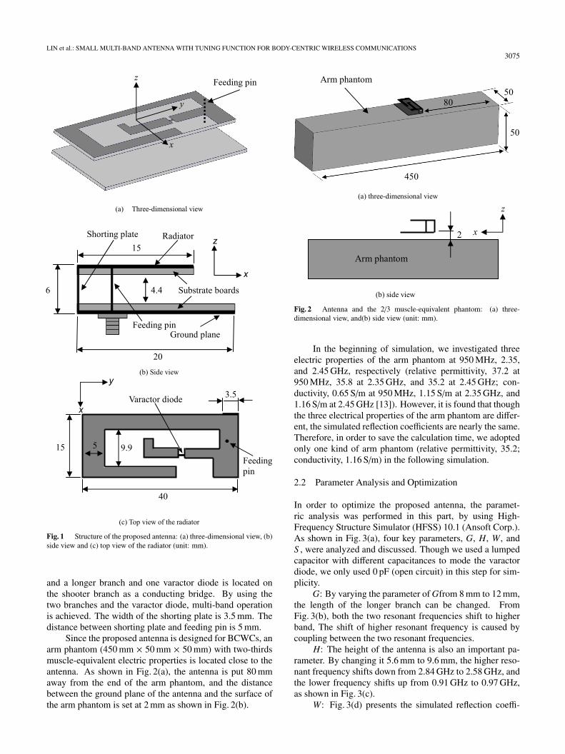
As demonstrated in Fig. 1, our proposed antenna is a pla-nar inverted-F antenna. In the antenna, there are two sub-strate boards, both with a thickness of 0.8 mm and a rela-tive permittivity of 2.17, and the distance between them is4.4 mm. As a result, the height of the antenna is 6 mm. Thelower substrate board has the area of 40 × 20 mm2, and theground plane is on the bottom layer of it, with the same area.The upper substrate board has the area of 40 × 15 mm2, andthe radiator is on the top layer of it. In Fig. 1(a) the dashline presents the feeding pin. Figure 1(b) presents the sideview of the proposed antenna. Figure 1(c) shows the topview of the radiator. The radiator includes a shorter branch
LIN et al.: SMALL MULTI-BAND ANTENNA WITH TUNING FUNCTION FOR BODY-CENTRIC WIRELESS COMMUNICATIONS3075
Fig. 1 Structure of the proposed antenna: (a) three-dimensional view, (b)side view and (c) top view of the radiator (unit: mm).
and a longer branch and one varactor diode is located onthe shooter branch as a conducting bridge. By using thetwo branches and the varactor diode, multi-band operationis achieved. The width of the shorting plate is 3.5 mm. Thedistance between shorting plate and feeding pin is 5 mm.
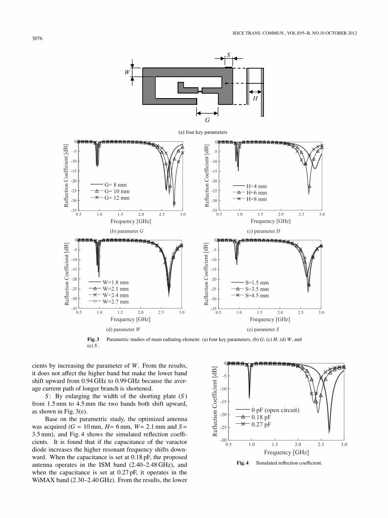
Since the proposed antenna is designed for BCWCs, anarm phantom (450 mm × 50 mm × 50 mm) with two-thirdsmuscle-equivalent electric properties is located close to theantenna. As shown in Fig. 2(a), the antenna is put 80 mmaway from the end of the arm phantom, and the distancebetween the ground plane of the antenna and the surface ofthe arm phantom is set at 2 mm as shown in Fig. 2(b).
Fig. 2 Antenna and the 2/3 muscle-equivalent phantom: (a) three-dimensional view, and(b) side view (unit: mm).
In the beginning of simulation, we investigated threeelectric properties of the arm phantom at 950 MHz, 2.35,and 2.45 GHz, respectively (relative permittivity, 37.2 at950 MHz, 35.8 at 2.35 GHz, and 35.2 at 2.45 GHz; con-ductivity, 0.65 S/m at 950 MHz, 1.15 S/m at 2.35 GHz, and1.16 S/m at 2.45 GHz [13]). However, it is found that thoughthe three electrical properties of the arm phantom are differ-ent, the simulated reflection coefficients are nearly the same.Therefore, in order to save the calculation time, we adoptedonly one kind of arm phantom (relative permittivity, 35.2;conductivity, 1.16 S/m) in the following simulation.
2.2 Parameter Analysis and Optimization
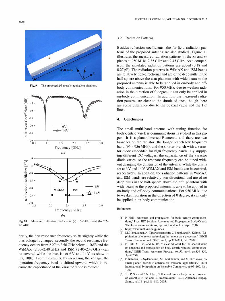
In order to optimize the proposed antenna, the paramet-ric analysis was performed in this part, by using High-Frequency Structure Simulator (HFSS) 10.1 (Ansoft Corp.).As shown in Fig. 3(a), four key parameters, G, H, W, andS , were analyzed and discussed. Though we used a lumpedcapacitor with different capacitances to mode the varactordiode, we only used 0 pF (open circuit) in this step for sim-plicity.
G: By varying the parameter of Gfrom 8 mm to 12 mm,the length of the longer branch can be changed. FromFig. 3(b), both the two resonant frequencies shift to higherband, The shift of higher resonant frequency is caused bycoupling between the two resonant frequencies.
H: The height of the antenna is also an important pa-rameter. By changing it 5.6 mm to 9.6 mm, the higher reso-nant frequency shifts down from 2.84 GHz to 2.58 GHz, andthe lower frequency shifts up from 0.91 GHz to 0.97 GHz,as shown in Fig. 3(c).
W: Fig. 3(d) presents the simulated reflection coeffi-
3076IEICE TRANS. COMMUN., VOL.E95–B, NO.10 OCTOBER 2012
Fig. 3 Parametric studies of main radiating element: (a) four key parameters, (b) G, (c) H, (d) W , and(e) S .
cients by increasing the parameter of W. From the results,it does not affect the higher band but make the lower bandshift upward from 0.94 GHz to 0.99 GHz because the aver-age current path of longer branch is shortened.
S : By enlarging the width of the shorting plate (S )from 1.5 mm to 4.5 mm the two bands both shift upward,as shown in Fig. 3(e).
Base on the parametric study, the optimized antennawas acquired (G = 10 mm, H= 6 mm, W= 2.1 mm and S=3.5 mm), and Fig. 4 shows the simulated reflection coeffi-cients. It is found that if the capacitance of the varactordiode increases the higher resonant frequency shifts down-ward. When the capacitance is set at 0.18 pF, the proposedantenna operates in the ISM band (2.40–2.48 GHz), andwhen the capacitance is set at 0.27 pF, it operates in theWiMAX band (2.30–2.40 GHz). From the results, the lower
Fig. 4 Simulated reflection coefficient.
LIN et al.: SMALL MULTI-BAND ANTENNA WITH TUNING FUNCTION FOR BODY-CENTRIC WIRELESS COMMUNICATIONS3077
Fig. 5 Simulated surface currents distribution at (a) 950 MHz, (b)2.35 GHz and (c) 2.45 GHz.
band (950–956 MHz) is also covered.To understand the multi-band operation of the proposed
antenna, the surface current distributions on the radiator at950 MHz, 2.35 and 2.45 GHz, were given in Fig. 5. Asshown in Fig. 5(a), the surface current flows from the feed-ing point to the end of the longer branch, whose path lengthis close to one quarter-wavelength of 950 MHz. Figure (b)and (c) show the surface currents flow from the feeding pointto the end of the shorter branch, whose path length is closeto one quarter-wavelength of 2.4 GHz.
3. Experimental Results and Discussion
3.1 Reflection Coefficients
As an implementation, a varactor diode of Skyworks(SMV2019-040LF) is adopted in our prototype antenna. Be-sides, as in Fig. 6, two RF chock inductors with 33 nH areadded to separate the DC signal and the RF signal. Based onits data sheet [10], a typical characteristic of capacitance isgiven in Fig. 7, so the varactor diode offers a tuning range ofcapacitance from 2.10 pF to 0.23 pF over a DC voltage from0 V to 20 V. It should be noted that, in order to reduce theeffects of DC lines, the DC lines are run through two holesboth dug on the two substrate boards, as shown in Fig. 8.The arm phantom in our paper is shown in Fig. 9. In ourexperiment, we dug a hole in the phantom for the connect-ing cable to the antenna. The arm phantom is comprised ofdeionized water, agar, sodium chloride, polyethylene pow-
Fig. 6 Layout of the tuning circuit.
Fig. 7 Capacitance vs reverse voltage.
Fig. 8 Prototype antenna.
der, TX-151, and sodium dehydroacetic acid [14]. In themeasurement, a foam layer with a thickness of 2 mm is usedto fix the distance between the antenna and the arm phan-tom.
Figures 10(a) and (b) present the measured reflectioncoefficients of the proposed antenna with the arm phantomat different bias voltages (6 V and 14 V). From the figures,
3078IEICE TRANS. COMMUN., VOL.E95–B, NO.10 OCTOBER 2012
Fig. 9 The proposed 2/3 muscle-equivalent phantom.
firstly, the first resonance frequency shifts slightly while thebias voltage is changed; secondly, the second resonance fre-quency occurs from 2.27 to 2.50 GHz below −10 dB and theWiMAX (2.30–2.40 GHz) and ISM (2.40–2.48 GHz) canbe covered while the bias is set 6 V and 14 V, as show inFig. 10(b). From the results, by increasing the voltage, theoperation frequency band is shifted upward, which is be-cause the capacitance of the varactor diode is reduced.
3.2 Radiation Patterns
Besides reflection coefficients, the far-field radiation pat-terns of the proposed antenna are also studied. Figure 11illustrates the measured radiation patterns in the xz and yzplanes at 950 MHz, 2.35 GHz and 2.45 GHz. As a compar-ison, the simulated radiation patterns are added (0.18 and0.27 pF). The radiation patterns in WiMAX and ISM bandsare relatively non-directional and are of no deep nulls in thehalf-sphere above the arm phantom with wide beam so theproposed antenna is able to be applied in on-body and off-body communications. For 950 MHz, due to weaken radi-ation in the direction of 0 degree, it can only be applied inon-body communication. In addition, the measured radia-tion patterns are close to the simulated ones, though thereare some difference due to the coaxial cable and the DClines.
4. Conclusions
The small multi-band antenna with tuning function forbody-centric wireless communications is studied in this pa-per. It is a planar inverted-F antenna and there are twobranches on the radiator: the longer branch low frequencyband (950–956 MHz), and the shorter branch with a varac-tor diode embedded for high frequency bands. By supply-ing different DC voltages, the capacitance of the varactordiode varies, so the resonant frequency can be tuned with-out changing the dimension of the antenna. While the bias isset at 6 V and 14 V, WiMAX and ISM bands can be covered,respectively. In addition, the radiation patterns in WiMAXand ISM bands are relatively non-directional and are of nodeep nulls in the half-sphere above the arm phantom withwide beam so the proposed antenna is able to be applied inon-body and off-body communications. For 950 MHz, dueto weaken radiation in the direction of 0 degree, it can onlybe applied in on-body communication.
References
[1] P. Hall, “Antennas and propagation for body centric communica-tions,” Proc. IET Seminar Antennas and Propagation Body-CentricWireless Communications, pp.1–4, London, UK, April 2007.
[2] http://www.mict.ynu.ac.jp/index[3] M. Hamalainen, A. Taparugssanagorn, J. Iinatti, and R. Kohno, “Ex-
ploitation of wireless technology in remote care processes,” IEICETrans. Commun., vol.E92-B, no.2, pp.373–378, Feb. 2009.
[4] P. Hall, Y. Hao, and K. Ito, “Guest editorial for the special issueon antennas and propagation on body-centric wireless communica-tions,” IEEE Trans. Antennas Propag., vol.57, no.4, pp.834–836,April 2009.
[5] P. Salonen, L. Sydanheimo, M. Keskilammi, and M. Kivikoski, “Asmall planar inverted-F antenna for wearable applications,” ThirdInternational Symposium on Wearable Computers, pp.95–100, Oct.1999.
[6] T.S.P. See and Z.N. Chen, “Effects of human body on performanceof wearable PIFAs and RF transmission,” IEEE Antennas Propag.Symp., vol.1B, pp.686–689, 2005.
LIN et al.: SMALL MULTI-BAND ANTENNA WITH TUNING FUNCTION FOR BODY-CENTRIC WIRELESS COMMUNICATIONS3079
Fig. 11 Simulated and measured radiation patterns (a) at 950 MHz in xz plane, (b) at 950 MHZ in yzplane, (c) at 2.35 GHz in xz plane, (d) at 2.35 GHz in yz plane, (e) at 2.45 GHz in xz plane, and (f) at2.45 GHz in yz plane (unit: dBi).
[7] P.J. Soh, G.A.E Vandenbosch, V. Volski, and H.M.R Nurul, “Char-acterization of a simple broadband textile planar inverted-F antenna(PIFA) for on body communications,” ICECom, Croatia, 2010, Sept.2010.
[8] N. Haga, K. Saito, M. Takahashi, and K. Ito, “Characteristics ofcavity slot antenna for body-area networks,” IEEE Trans. AntennasPropag., vol.57, no.4, pp.837–843, April 2009.
[9] Z. Li, K. Saito, M. Takahashi, K. Ito, and Y. Huang, “A small pla-nar inverted-F antenna for body-centric wireless communications,”Proc. Int’ Sym. on Antennas and Propag., pp.1–4, Macau, China,Nov. 2010.
[10] S. Zhu and R. Langley, “Dual-band wearable textile antenna onan EBG substrate,” IEEE Trans. Antennas Propag., vol.57, no.4,pp.926–935, April 2009.
3080IEICE TRANS. COMMUN., VOL.E95–B, NO.10 OCTOBER 2012
[11] S. Zhu and R. Langley, “Dual-band wearable antennas over EBGsubstrate,” Electron. Lett., vol.43, no.3, pp.141–142, Feb. 2007.
[12] Data Sheet of SMV2019-040LF varactor diode Application Note[Online]. Available: http://www.skyworksinc.com/
[13] http://transition.fcc.gov/oet/rfsafety/dielectric.html[14] W. Xie, K. Saito, M. Takahashi, and K. Ito, “Performances of an
implanted cavity slot antenna embedded in the human arm,” IEEETrans. Antennas Propag., vol.57, no.4, pp.837–843, April 2009.
Chia-Hsien Lin was born in Taichung, Tai-wan, in October 1983. He received the B.S.degree in electronic engineering from NationalUnited University, Maioli, Taiwan, in 2007 andthe M.S. in Electrical Engineering from Na-tional University of Tainan, Taiwan, in 2009.His main research interests include small anten-nas for body area network, design of microstripfilters and reconfigurable antennas.
Zhengyi Li was born in Xi’an, China, inFebruary 1982. He received the B.E. degreein Information Engineering from Xi’an JiaotongUniversity, Xi’an, China, in 2004, and the Ph.D.degree in Electronic Engineering from TsinghuaUniversity, Beijing, China, in 2010. From 2010to 2012, he was a Postdoctoral Researcher atthe Research Center for Frontier Medical En-gineering, Chiba University. He is currently aResearcher at Fujitsu Laboratories Ltd. His re-search interests include small antennas for body-
centric wireless communications, MIMO antennas, and reconfigurable an-tennas. Dr. Li was the recipient of the 2010 Asia-Pacific Radio ScienceConference (AP-RASC’10) Young Scientist Award in 2010.
Kazuyuki Saito was born in Nagano, Japan,in May 1973. He received the B.E., M.E. andD.E. degrees all in electronic engineering fromChiba University, Chiba, Japan, in 1996, 1998and 2001, respectively. He is currently an As-sociate Professor with the Research Center forFrontier Medical Engineering, Chiba Univer-sity. His main interest is in the area of medi-cal applications of the microwaves including themicrowave hyperthermia. Prof. Saito receivedthe IEICE AP-S Freshman Award, the Award for
Young Scientist of URSI General Assembly, the IEEE AP-S Japan Chap-ter Young Engineer Award, the Young Researchers’ Award of IEICE, andthe International Symposium on Antennas and Propagation (ISAP) PaperAward in 1997, 1999, 2000, 2004, and 2005 respectively. Dr. Saito is amember of the Institute of Image Information and Television Engineers ofJapan (ITE), and the Japanese Society for Thermal Medicine.
Masaharu Takahashi was born in Chiba,Japan, in December, 1965. He received the B.E.degree in electrical engineering in 1989 fromTohoku University, Miyagi, Japan, and the M.E.and D.E. degrees both in electrical engineer-ing from Tokyo Institute of Technology, Tokyo,Japan, in 1991 and 1994 respectively. He was aResearch Associate from 1994 to 1996, an As-sistant Professor from 1996 to 2000 at MusashiInstitute of Technology, Tokyo, Japan, and anAssociate Professor from 2000 to 2004 at To-
kyo University of Agriculture and Technology, Tokyo, Japan. He is cur-rently an Associate Professor at the Research Center for Frontier MedicalEngineering, Chiba University, Chiba, Japan. His main interests are elec-trically small antennas, planar array antennas, and electromagnetic com-patibility. Prof. Takahashi received the IEEE Antennas and PropagationSociety (IEEE AP-S) Tokyo chapter young engineer award in 1994.
Koichi Ito was born in Nagoya, in June,1950. He received the B.S. and M.S. degreesfrom Chiba University, Chiba, Japan, in 1974and 1976, respectively, and the D.E. degreefrom the Tokyo Institute of Technology, To-kyo, Japan, in 1985, all in electrical engineering.From 1976 to 1979, he was a Research Asso-ciate at the Tokyo Institute of Technology. From1979 to 1989, he was a Research Associate atChiba University. From 1989 to 1997, he was anAssociate Professor at the Department of Elec-
trical and Electronics Engineering, Chiba University, and is currently a Pro-fessor at the Graduate School of Engineering, Chiba University. He hasbeen appointed as one of the Deputy Vice-Presidents for Research, ChibaUniversity, since April 2005. In 1989, 1994, and 1998, he visited the Uni-versity of Rennes I, France, as an Invited Professor. Since 2004 he hasbeen appointed as an Adjunct Professor to Institute of Technology Ban-dung (ITB), Indonesia. His main research interests include analysis anddesign of printed antennas and small antennas for mobile communications,research on evaluation of the interaction between electromagnetic fieldsand the human body by use of numerical and experimental phantoms, mi-crowave antennas for medical applications such as cancer treatment, andantennas for body-centric wireless communications. Dr. Ito is a memberof the American Association for the Advancement of Science, the Insti-tute of Image Information and Television Engineers of Japan (ITE) and theJapanese Society for Thermal Medicine (formerly, Japanese Society of Hy-perthermic Oncology). He served as Chair of the Technical Group on Radioand Optical Transmissions, ITE from 1997 to 2001 and Chair of the Techni-cal Group on Human Phantoms for Electromagnetics, IEICE from 1998 to2006. He also served as Chair of the IEEE AP-S Japan Chapter from 2001to 2002 and TPC Co-Chair of the 2006 IEEE International Workshop onAntenna Technology (iWAT2006). He currently serves as General Chair ofthe iWAT2008 to be held in Chiba, Japan in 2008, Vice-Chair of the 2008International Symposium on Antennas and Propagation (ISAP2008) to beheld in Taiwan in 2008 and as an Associate Editor for the IEEE TRANS-ACTIONS ON ANTENNAS AND PROPAGATION. He also serves as aDistinguished Lecturer and an AdCom member for the IEEE Antennas andPropagation Society since January 2007.


![Van Oord UK Ltd & Anor v Allseas UK Ltd [2015] EWHC 3074 (TCC) (12 November 2015)](https://static.documents.pub/doc/80x56/5695d0c51a28ab9b0293cb20/van-oord-uk-ltd-anor-v-allseas-uk-ltd-2015-ewhc-3074-tcc-12-november.jpg)
