Dr Nicholas I? Cheremismoft REM and Paul N. Cherernisrnof[ REM Special The Plastics Waste Problem Report: n 1987 more than 55 billion lb of plastic resin were sold in the United States alone, with industry reports projecting an increase by a factor of two to three toward the end of the century. Plastic disposal totaled 7% of the solid waste stream. With the favorable industry out- look for new and expanding uses of plastics and elastomers, the outfall of disposal is expected to triple over the next decade placing the added burden on solid waste disposal. The option of landfill as a disposal method is rapidly diminishing. The number of legal landfills has declined from a 1976 figure of 18,000 to oply 9,000 today. Public concem has prevented new landfill facilities from opening and regulatory restraints are making this disposal option expensive. It is clear that plastics disposal has reached crisis propor- tions and that resolution of the disposal problem is neces- sary. This crisis can be expected to impact on industry in three ways: Increased direct costs, reduced price competi- tiveness, and reduced plastic uses. In this special editorial report, an overview of the problem, its impact on industry costs and alternatives to waste disposal are reviewed. Effects on lndustry and the Consumer The cost of plastic waste disposal varies by industry seg- ment and region, however the net effect is the same. Pre- ston and Frank (1989) illustrate the effect by way of exam- ple in the automotive industry. They note that for one plastic supplier of automotive parts, the cost for disposal rose from $2/ton in the 1970’s to $50/ton in the 1980‘s. In this case, their prime disposal site is reaching capacity, and they expect to pay over $100/ton for disposal by 1990. Nationally, disposal costs are expected to reach and per- haps exceed $2OO/ton in the mid 1990’s. As noted earlier, landfills have declined from 18,000 a decade ago to half that number today, and by the early 1990’s, a further halv- ing is expected. Shortages of disposal options have forced companies to pay considerably more for disposal. The obvious increase in direct cost to any company is a reduction in its profits. Companies are forced to pass these costs to their customers as a greater percentage of the sell- ing price. By passing on these costs, they reduce their com- petitiveness in the world market. In the example cited, the company passed on disposal costs as O.OOS% of indirect cost to the customer in the 1980’s, which translates into a penny per pan. Because of the expected increase in dispos- al costs. this may be expected to impact the part price to 0.01% or $0.02 per part. Although on a per unit part basis this cost may seem insignificant, in terms of plant output it translates to over $30.000 per year. By comparison. com- petitors in Canada and Europe are paying disposal costs 58 that amount to about one fourth per year for comparable production rates. The net result in the above example is a loss in competi- tiveness both within U.S. markets and abroad. There is, in fact, a domino effect in that the penalty for high waste dis- posal costs affects everyone; from the raw material suppli- er, to the parts manufacturer. Another example will illustrate how several support industries can be affected. In automotive manufacturing, plastic and elastomeric parts that are ultimately assembled by the car manufacturer are produced elsewhere. Material suppliers will almost always produce off-specification rub- ber or plastic. Some of this material can be reprocessed, another portion can possibly be sold at a lower price as off- spec grade in other applications, and ultimately there is some material which is unusable. The parts manufacturer (Le., the plastics/polymer processor) who fabricates the weatherstrip, the hose, the bumper guard, etc. always has a scrap stream. With some plastics resins, this scrap can be reprocessed. However with other resins, and particularly in the case of compounded rubbers, the scrap is part of the ultimate waste stream. Finally, the auto manufacturer face.. a waste stream from defective and damaged parts as well a:. alterations on parts during assembly. The consumer, of course, is eventually left with the largest potential waste per product when the automobile is no longer functioning. Dur- ing an auto’s life however, the consumer helps small busi- nesses to contribute to the waste stream through car repairs. replacement parts, servicing, etc. Public outcry against plastics wastes has not ye: stemmed from its direct impact on the purse but rather from: the concem for the environment. As examples, Washington State has banned the use of disposable diapers because the plastic does not degrade in landfills. Suffolk County, NY has banned “point of use’‘ plastic use. which is a ban that affects the fast food industry where food is served to patrons in Styrofoam containers. Obviously such bans ulti- mately affect the resin suppliers. If such bans continue to gain impetus, the demand for plastic products and therefore plastic resin will decrease. These concems again are part or the direct cost to industry from plastic/elastomeric use. In addition to direct costs to industq. there are severai indirect costs that also impact on companies that produce or process plastic resins and/or elastomers. These costs are those associated with compliance. The Office of Manage- ment and Budget (OMB) conducted a 1980 study on the cost impact of environmental reguiations. Their repori showed that each page of regulation added to the Fedet-ai Regisrei- resulted in $10 million costs to industry for com- pliance. In 1985 a record 750 pages were added to the Fed AUGUST 1965
Transcript
Dr Nicholas I? Cheremismoft REM and Paul N. Cherernisrnof[ REM
Special The Plastics Waste Problem
Report: n 1987 more than 55 billion lb of plastic resin were sold in the United States alone, with industry reports projecting an increase by a factor of two to three
toward the end of the century. Plastic disposal totaled 7% of the solid waste stream. With the favorable industry out- look for new and expanding uses of plastics and elastomers, the outfall of disposal is expected to triple over the next decade placing the added burden on solid waste disposal.
The option of landfill as a disposal method is rapidly diminishing. The number of legal landfills has declined from a 1976 figure of 18,000 to oply 9,000 today. Public concem has prevented new landfill facilities from opening and regulatory restraints are making this disposal option expensive.
It is clear that plastics disposal has reached crisis propor- tions and that resolution of the disposal problem is neces- sary. This crisis can be expected to impact on industry in three ways: Increased direct costs, reduced price competi- tiveness, and reduced plastic uses. In this special editorial report, an overview of the problem, its impact on industry costs and alternatives to waste disposal are reviewed.
Effects on lndustry and the Consumer The cost of plastic waste disposal varies by industry seg-
ment and region, however the net effect is the same. Pre- ston and Frank (1989) illustrate the effect by way of exam- ple in the automotive industry. They note that for one plastic supplier of automotive parts, the cost for disposal rose from $2/ton in the 1970’s to $50/ton in the 1980‘s. In this case, their prime disposal site is reaching capacity, and they expect to pay over $100/ton for disposal by 1990.
Nationally, disposal costs are expected to reach and per- haps exceed $2OO/ton in the mid 1990’s. As noted earlier, landfills have declined from 18,000 a decade ago to half that number today, and by the early 1990’s, a further halv- ing is expected. Shortages of disposal options have forced companies to pay considerably more for disposal.
The obvious increase in direct cost to any company is a reduction in its profits. Companies are forced to pass these costs to their customers as a greater percentage of the sell- ing price. By passing on these costs, they reduce their com- petitiveness in the world market. In the example cited, the company passed on disposal costs as O.OOS% of indirect cost to the customer in the 1980’s, which translates into a penny per pan. Because of the expected increase in dispos- al costs. this may be expected to impact the part price to 0.01% or $0.02 per part. Although on a per unit part basis this cost may seem insignificant, in terms of plant output it translates to over $30.000 per year. By comparison. com- petitors in Canada and Europe are paying disposal costs
58
that amount to about one fourth per year for comparable production rates.
The net result in the above example is a loss in competi- tiveness both within U.S. markets and abroad. There is, in fact, a domino effect in that the penalty for high waste dis- posal costs affects everyone; from the raw material suppli- er, to the parts manufacturer.
Another example will illustrate how several support industries can be affected. In automotive manufacturing, plastic and elastomeric parts that are ultimately assembled by the car manufacturer are produced elsewhere. Material suppliers will almost always produce off-specification rub- ber or plastic. Some of this material can be reprocessed, another portion can possibly be sold at a lower price as off- spec grade in other applications, and ultimately there is some material which is unusable. The parts manufacturer (Le., the plastics/polymer processor) who fabricates the weatherstrip, the hose, the bumper guard, etc. always has a scrap stream. With some plastics resins, this scrap can be reprocessed. However with other resins, and particularly in the case of compounded rubbers, the scrap is part of the ultimate waste stream. Finally, the auto manufacturer face.. a waste stream from defective and damaged parts as well a:. alterations on parts during assembly. The consumer, of course, is eventually left with the largest potential waste per product when the automobile is no longer functioning. Dur- ing an auto’s life however, the consumer helps small busi- nesses to contribute to the waste stream through car repairs. replacement parts, servicing, etc.
Public outcry against plastics wastes has not ye: stemmed from its direct impact on the purse but rather from: the concem for the environment. As examples, Washington State has banned the use of disposable diapers because the plastic does not degrade in landfills. Suffolk County, NY has banned “point of use’‘ plastic use. which is a ban that affects the fast food industry where food is served to patrons in Styrofoam containers. Obviously such bans ulti- mately affect the resin suppliers. If such bans continue to gain impetus, the demand for plastic products and therefore plastic resin will decrease. These concems again are part or the direct cost to industry from plastic/elastomeric use.
In addition to direct costs to industq. there are severai indirect costs that also impact on companies that produce or process plastic resins and/or elastomers. These costs are those associated with compliance. The Office of Manage- ment and Budget (OMB) conducted a 1980 study on the cost impact of environmental reguiations. Their repori showed that each page of regulation added to the Fedet-ai Regisrei- resulted in $10 million costs to industry for com- pliance. In 1985 a record 750 pages were added to the F e d
AUGUST 1965
Register had effects 0
The cost brings additi regulations. Other costs operations s rems. This. costs. 7
I
CONVEI
Flor
It is im sors are tC disposal. promulga have stem lic has on des concc section). i IS aware (
to addres: tinue to z further re standpoir regulatioi mce of S necessac allied ind to provid
Source One a
system ti category which ti- Tystem i:
POLLUTIC
oarable
)mpe:i- r is. In
ste ais- >uppll-
upport turing. ”led latenal in rub- -es\ed.
f-
!er: 1s
murer es the j has a :an be arly in
of the r faces well as ier, of ste per ,. Dur-
:pairs,
i t yet r from ington se the v. NY n that ed to
b ultl- iue to refore tart of
:vera1 ice or ’s are nage- n the eport derai com- Fed-
I busi-
1989
ru i Rr:r.srcr, o f which approxiinately 10% of these pages
The cost o t compliance wi th regulations i n e v i t a b l y .Trings additional expenditures. To assure compiiance wirh :-rzulations. companies are often forced to hire consuitants. Other zests inc!ude the increased requirements for landfiil )perations such as Liners and groundwater monitoring sys - :Ins. This, at least in part. has led to increased disposal
erfects on the plastic industry.
fiS[S.
ONSUYER
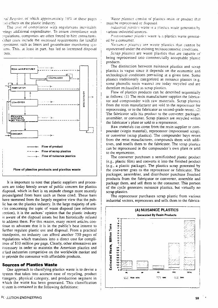
__t_ Flow of product
---- +- Flow of scrap plastics
........ >... I Flow of nuisance plastics
Flow of plastics products and plastics waste
It is important to note that plastic suppliers and proces- sors are today keenly aware of public concem for plastics disposal, which in fact is an. attitude change more recently promulgated from bans such as those cited. These bans have stemmed from the largely negative view that the pub- lic has on the plastics industry. In the large majority of arti- c!es conceming the topic of waste disposal (see reference xction), it is the authors’ opinion that the plastic industry is aware of the disposal issues but has historically refused to address them. For this reason, many recent articles con- tinue to advocate that it is in the public’s best interest to further regulate plastic use and disposal. From a practical standpoint, no industry can afford another 750 pages of regulations which translates into a direct cost for compli- ance of $10 million per page. Clearly, other alternatives are necessary in order to maintain the American plastics and s’lied industries competitive on the worldwide market and tc piovide the consumer with affordable products.
Sources of Plastics Waste One approach to classifying plastics waste is to devise a
system that takes into account ease of recycling, product category, physical category, and production segment in ubich the waste has been generated. This classification s:. stem is contained in the following definitions:
p( ,-LUTION ENGINEERING
\,Vu.sre plasrics consist 01‘ piastics resin o r produc: :hiit n u s t be reprocessed or disposed.
!ud’il>rr-:d !7iasric.s waste / s a plastics waste ;enera:cd b! various industnai sources.
Pnsrconsumer piusrics waste is a plastics waste generat- ed by a consume:.
Nuisuncr ,7iosrics are waste piastics [hat cannot be reprocessed under the existing technoeconomic conditions.
Scrap plastics are waste piastics that are capable of being reprocessed into commercially acceptable plasric products.
The distinction between nuisance plastics and scrap plastics is vague since it depends on the economic and technological conditions prevailing at a given time. Some plastics traditionally categorized as nuisance plastics (e.g. some phenolic resin wastes) are roday recycled and are therefore reclassified as scrap plastics.
Flow of plastics products can be described sequentially as follows: (1) The resin manufacturer supplies the fabrica- tor and compounder with ism' materials. Scrap plastics from the resin manuiacturer are sold to the reprocessor for reprocessing. or to the fabricator as second-grade resins. 2 ) The fabricator sells his product to the converter, packager. assembler. or consumer. Scrap plastics are recycled within the fabricator‘s plant or sold to a reprocessor.
Raw materials can come from the resin supplier or com- pounder (virgin material), reprocessor (reprocessed scrap), or converter (scrap plastics). The compounder buys resins from the resin manufacturer. compounds them with addi- tives, and resells them to the fabricator. The scrap plastics can be reprocessed in the compounder’s own plant or sold to the reprocessor.
The converter purchases a semifinished plastic product (e.g., plastic film) and converts it into the finished product (e.g., a plastic package). The plastics scrap generated by the converter goes to the reprocessor or fabricator. The packager, assembler, and distributor purchase finished products from the fabriptor or converter. assemble and package them, and sell them to the consumer. This portion of the cycle generates nuisance plastics, but virtually no scrap platics.
The reprocessor purchases scrap plastic from various industrial sectors, reprocesses and sells them to the fabrica-
(A) NUISANCE PLASTICS Generated By Resin Products
21 ,
tor. Small amounts of scrap plastics generated by the repro- cessor are recycled in the plant. As noted earlier. the con- sumer. at thc end of the ?!astics cycle. generates onl? nui- sance plastics. which eventuallj end u p together w.i!n nuisance plastics generated by the industrial sector in Iand- fills or an incinerator.
(B) NUISANCE PLASTICS Generated By Resin Products
4
I :i
I
u -1
i. , ; I 1 4
The vast majority of articles pointing to waste problems with plastics concern postconsumer waste, with very little attention ziven to industrial plastics waste. The amount of waste depends upon such factors as the complexity of the polymerization process. the number of grades produced in a single plant. and the number of manufacturing steps. The least amount of waste is typically generated in the' manu- facturing of polyethylene, the most in the manufacturing of PVC.
Plastics waste is generated during the polymerization process (reactor scrappings , unsuccessful runs, etc.). com- pounding (extruder purgings, unsuccessful runs). and the shipment and storage.
iMost waste plastics generated industrially by blob molding come from the pinchoff. Some products with a large percentage of pinchoff (e.g.. bottles with handles j can generate up to 40% waste. Waste plastics generated by injection molding come from sprues and runners (routinely reground and added to the virgin resin in amounts of 5 to 20%). machine setup, and machine purging. There are a variety of extrusion operations: a few examples of which include sheet and film extrusion. extrusion coating, wire and cable. profile and pipe, and coextrusion.
Extrusion processes generate waste during equipment startups. from purging and trimming, and cutting of the final product.
Waste plastics are generated in the calendering process in the form of drippings from the mixers and the calender, and from the trimmings and product rejects.
Rotomolding generates plastics waste in the form of trim flash at mold parting lines, removed openings in the prod- uct. and product rejects.
A large portion of industrial plastics waste generated by th: fabricator is in a relatively clean. chemically uniform state. and can be easily reprocessed. Only about one-third of the plastics waste generated by that segment is classified as nuisance plastic. The compounder and reprocessor
60
account for only small percentages of overall p1ast:c Plastic waste. Both generate wasre by purging of the compoundin; j,qtributor equipment and unsuccessful runs (off-specification prod ,rsste gene uctsi. About 10% of the total throughput of these two see erable cor ments ends up as a plastic waste. a large portion of it classi. unsuitable
The converter purchases semifinished plastic product! In 198( from the fabricator and converts them into finished prod- Th ucts. Since the converter usually deals with a number of reach 1 semifinished products, the waste (in the form of trim. 01 <ne majori rejected products') is more difficult to reprocess than tha! by styrene generated by the fabricator. Relatively clean and uniform &ued thrc scrap plastic (for example. decorated reject cups) can be ate throug sold to the reprocessor to be pelletized and sold as a sec. merit pro( ond-grade resin. Less than 50% of waste plastics generated COnstitut: by this segment is suitable for reprocessing. waste.
- Al tho~
fied as scrap plastic. be about 0
I ~ solid was
TYPES OF CRUSHERS ~ 1
Cutting Type ~
SHREDDERS, CUTTERS & CHIPPERS
I input 1
\ \ - a * ' .. rejects , .:'
I
HCATfl l - .
e=
~
i I I
Sepa: hlu1
raw m; some c dispos: ative 1
about : new d AlthoL pal re! cl: th: separa
SI: RASP MILL cal se
prsssi
AUGUST 19E PCLL'
accoc
_ _ _ _ -.-- -
plasti )oundii i n pro’ two se it clasz
xoduc :d pro1 mber I
trim. i han th, unifon I can t .s a sec merate
.
TING
Plastic waste generated by the packager, assembler, and distributor falls under the category of nuisance waste. The waste generated by this sector is characterized by a consid- erable contamination with nonelastic matter and thus is unsuitable for reprocessing. A 1980 estimate showed this to be about 0.16 million tons of waste.
In 1980 plastics constituted only 2 to 3% of municipal refuse. This amount has increased steadily and is expected IO reach 10 to 15% by the year 2000. Polylefins constitute the majority (70%) of plastics in the disposal area followed by styrene polymers and PVC. This rate of growth has con- tinued through the 1980’s and it appears that it may acceler- ate through the 1990’s due to the introduction of new poly- meric products and end uses. As expected, packaging waste constitutes the majority of plastic components of solid waste.
Although plastics constitute only a small portion of total solid waste, on a national scale the total amount of plastic In the refuse is staggering. For many years incineration and iandfill were the main, if not the only methods of solid waste disposal. Because of the drive toward energy and materials conservation, as well as the concern about the environment, new waste disposal options are being devel- oped and implemented.
.,I .U
WET PULPING PROCESS
Separation Methods for Municipal Refuse Municipal refuse can be treated as a potential source of
raw materials. Not only do the individual constituents have some economic value, but municipal refuse, if it must be disposed of without the recovery of value, actually has neg- ative value. The scarcity of raw materials and concern Ibout environmentally safe disposal of refuse have added a new-dimension to the question of recycling solid wastes. Although plastics constitute only a small portion of munici- pal refuse, the actual quantity is enormous. In order to recy- cle the components of municipal refuse, they must first be separated.
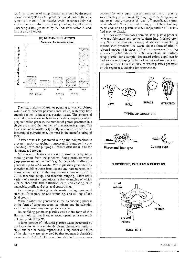
Size reduction of municipal solid refuse is the mechani- cal separation of the material into smaller pieces. It is xcomplished by the mechanical forces of tension, com- xession, and shear applied by crushers, shears, shredders,
chippers, rasp mills, drum pulverizers. disk mills. pulpers, and hammermills.
Shredders and chippers empIoy both tensile and shearing force. The butting type of machine is not widely used in the size reduction of municipal refuse because of the vulnera- bility of the blades to damage. The “pierce and tear” types of machines use toothed wheels rotating at different speeds, which penetrate, shear, and shred the material. This type of shredder is useful in the reduction of ductile or fibrous materials, and is often used on the paper and fiber portion of municipal solid refuse. Rasp mills use tension, compres- sion, and shear forces. The rotor, fitted on a vertical shaft, carries heavy rasping arms (up to 25 ft in diameter) which force the waste over rasping pins and through holes in the bottom of the chamber. A reject chute is periodically opened to allow the exit of items too bulky and durable to be properly reduced. Drum pulverizers have an action simi- lar to the rasp mills. The waste passes through a rotating drum of circular, octagonal, or hexagonal design containing stationary or counter-rotating beaters or baffles. The reducible material is tom and pushed through holes in the drum while the nonreducible portion leaves at the lower end.
A disk mill consists of a single rotating disk and a fixed contact surface, or two counterrotating high-speed disks. Refuse introduced between the disks is subjected to repeat- ed impact from a rotating disk or segmented wheel. Materi- al is reduced in size until it passes through openings in the fixed contact surface. Disk mills are limited to small parti- cle size feed.
Hammermills comprise the largest proportion of munici- pal solid waste size reduction equipment. They consist of a single or multiple rotor axle with attached hammers, and work by rapidly applying the forces of tension, compres- sion, and shear. There are two general types of hammer- mills: The swing hammer type (hammers mounted flexibly to the rotor shaft) and the rigid hammer type (hammers mounted rigidly to the fotor shaft). The action necessary to produce size reduction is obtained by positioning fixed blocks on the inside of the hammermill wall. Hammermills may be used for a broad range of feed materials.
Manual separation is the oldest technique. The method is sometimes used at the incoming feed belt to scavenge easily separated items. Hand separation of pzper, card- board, glass containers, etc., is best practiced at the source.
Widely used types of equipment for gravity separation are vibrating tables, ballistic separators, inclined conveyors for removal of stones and other heavy particles, and flu- idized bed separators.
Air classification is a method based on three parameters. namely size, specific gravity, and shape. Generally, zigzag or similar-shaped columns are used. Air enters at the bot- tom of the column and the material to be separated, in the middle. A series of columns with different geometries or flow rates will produce several grades of materials. Usually, the light fractions at the top are coilected in cyclone separa- tors, while the air and dust are returned to the column. Instead of a vertical column separator, a vortex classifier may be used in which a radially inward flowing air vortex replaces the upward flow. Other types of air classifiers uti- lize horizontal air flow, rectangular chamber with zigzag baffles, a rotary cylinder and a current of air, and vertical vanes. The choice of a specific system depends on the type
)OLLUTION ENGINEERING 61
of feed and the desired degree of separation. Air classifica- tion is the most widely used technique for the separation of solid wastes.
Magneiic separation is used for the removal of ferrous metals. Separation is achieved by mechanisms such as magnetic pulleys. dry and wet drum separators, and cross- belt separators.
Eiectrosraiir separation is similar to magnetic separa- tion in that it relies on the ability of some materials, such as plastics or paper, to acquire and hold an electrostatic charge. The particles are attracted to a charged roll or belt, or are deflected in an electrostatic field.
Processes for separating components of solid wastes may be classified as wet or dry. Dry processes are generally simpler, require lower energy input, and have fewer poten- tial environmental problems. Wet processes are usually capable of producing much cleaner and more uniform prod- ucts. Dry and wet separation techniques may be used as parts of the same process. The Black-Clawson and Flakt systems, are based on the principles of the wet and dry pro- cesses, respectively.
Mixtures of plastics and paper are a common product of municipal waste dry separation plants. To increase the value of the product, the mixture has to be separated into its components. The main problem in separation derives from the aerodynamic similarity of plastic film and paper. Three main principles can be used as the basis of separation meth- ods: ( 1 ) The application of heat, (3 ) wet pulping and (3) electrodynamic separation.
The “hot cylinder” method is a separation device which consists of an electrically heated. chromeplated cylinder enclosed within a hollow rotating tube fitted with vanes to ensure a tumbling action about the heated cylinder. The drum and the heated cylinder rotate in opposite directions. Material is fed into the drum through a sheet metal tube inserted at the entrance. Plastic materials coming into con- tact with the hot cylinder melt and are removed by the doc- tor b!ade. Removal of over 90% of plastics from the paper can be achieved. The plastic stream is relatively paperfree: 1 % or less of paper contaminants can be achieved.
A large amount of waste PVC-coated fabric is available. mainly from companies involved in its manufacture or con- version. The waste mixture is transported in a hot gas stream generated by the heater. which causes the thermo- plastic film to contract. thus reducing its surface area. The mixture is discharged through a cyclone onto a conveyer, which feeds it into an air separator. Air drawn through the separator carries wastepaper out through the exit duct while thermoplastic particles fall to the bottom of the classifier and are discharged. An almost complete separation of plas- tics and paper can be achieved using this method.
There is also a patented wet separation process applica- ble to the recovery of plastics from the light fraction obtained from the dry separation plant. It can also form a basis for a complete wet separation process. A conveyer delivers-waste material to a shredder. The output from the shredder is transferred to an air classifier. The light fraction from the air classifier comprises approximately 60% paper, 20% plastics. and the balance rags and vegetation residue. The light fraction is transported to a pulper equipped with rotor and extraction plate having relatively small perfora- tions. Pulped paper is capable of passing through the open- ings. Plastic particles retained in the tub are discharged
62
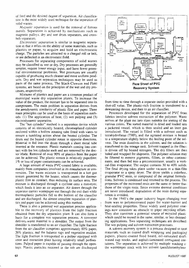
Flow Sheet of PVC Recovery System
from time to time through a separate outlet provided with a shut-off value. The plastic-rich fraction is transferred to a dewatering device. and then to an air classifier.
Processes developed for the separation of PVC from fabrics involve solvent extraction of the polymer. Waste arrives at the plant cut into sizes suitable for sorting of the various colors. The sorted material is dried and loaded into a jacketed vessel. which is then sealed and an inert gas introduced. The vessel is filled with a solvent such as tetrahydrofuran (THF), and the agitated mixture is heated to a temperature slightly below the boiling point of the sol- vent. The resin dissoives in the solvent, and the solution i; transferred to the storage tank. Solvent trapped in the fiber; is driven off by heated nitrogen. The dry fibers are theij baled and wrapped for shipment. The polymer solution may be filtered to remove pigments, fillers. or other contami- nants, and then fed into a preconcentrator, usually a verti- cal-film evaporator. The output contains 30 to 40% solids. The final drying takes place under vacuum in a thin-film evaporator or a spray dryer. The dryer yields a colorless. granular PVC resin, or compound of the original formula- tions. Solvent is condensed and returned to the process. The properties of the recovered resin are the same or better thai; those of the virgin resin. Since extreme thermal conditions are never introduced. degradation of the resin during sepa- ration is avoided.
In the 1940’s the paper industry began changing over from wax to polymercoated paper for water-barrier and heat-sealing properties. These widely used polymer coat- ings now constitute an obstacle to paper recycling efforts They also constitute a potential source of recycled plasti: which could be reused in the same, similar. or less demand- ing applications. Two separating techniques are described: The wet pulping and solvent extraction processes.
A solvent recovery system is a process designed to treat materials such as coated draft wrapping and packaging papers. plastic-coated food board, oil-saturated draft. waxed cup stocks. and asphalt-laminated corrugated con tainers. The separation is achieved by multiple washing c the wastepaper stock with hot solvent (perchloroethylenr
AUGUST 1985
3r:d steai the finai steps:
1. Ai dryer.
2. so 3. Re
by stem 4. Stt 5. s tt 6. So
adhesive ble reus
Both occur a: ing sep. ods. (7- and (3 ) tial for of indu ration c questio
Primz Prin
Dated r thermo used a‘ ratios. in-plar lems e of the loss in proces nation
Ch: after I: ly due occur avera molec unsar Then- inp ar the m occur mole, lar N Evoli secor cal c branc
R. lead ing c mai c
halo: chlo: Tne
C mel‘ degi
POL
bulk-d
r - f
-
F1l.1 J Cqn.”, .”.
f.,,,,
1 with i red to E
'.ram . Waste ; of the led into iert gas ;uch as heated
the sol- Jtion is
fibers re then 3n may intami- 3 verti- solids. in-film orless, rmula- 3s. The ?r than ditions ; sepa-
g over :r and . coat- ,fforts. Aastic mand- .ribed:
3 treat aging draft, I con- ing of dene)
1989
md steam stripping the residual solvent from the fiber after .he final wash. The process is comprised of the following ;teps:
1. Air-dry waste material is charged into the dissolver- dryer.
2. Solvent extraction is camed out. 3. Residual solvent is removed from the clean material
4. Steam-dry material is ready for pulping. 5. Steam is condensed and the solvent decanted. 6. Solvent is distilled, recovered and reused; the coating,
adhesive, or impregnating polymer is recovered for possi- ble reuse.
Both industrial and postconsumer plastics wastes often occur as mixtures of generic groups of plastics. The follow- ing separation techniques are possible: [ 1) Float/sink meth- ‘Ids, (2) processes utilizing difference in surface tension, .md (3) solvent extraction. These processes have the poten- rial for separating simple two- or three-component mixtures of industrial plastic wastes, but their usefulness in the sepa- ration of a complex postconsumer plastic waste mixture is questionable.
by steam evaporation.
Primary Recycling Primary recycling involves using uniform, uncontami-
nated plastic waste to manufacture plastic products. Only .hennoplastic waste can be directly reprocessed: It can be Jsed alone or, more often, added to virgin resin at various ratios. Primary recycling can be performed by the processor in-plant or through outside reprocessors. The main prob- lems encountered in primary recycling are: (1) Degradation of the material due to repeated processing, resulting in a loss in such properties as appearance, chemical resistance, processability, and mechanical characteristics; (2) contami- nation of the reprocessed plastic; and (3) handling of low- bulk-density scrap such as film or foam.
Changes in the physical properties of plastics, observed after processing at elevated temperatures, are almost entire- ly due to changes in polymer structure. Changes that may occur in the molecular structure are: (1) Reduction of the average molecular weight, (2) increase of the average molecular weight due to crosslinking, and (3) formation of unsaturation or cyclization due to side-chain reactions. Thermal and thermo-oxidative degradation and cross-link- ing are the most important factors involved. A decrease in the molecular weight in the case of main chain scission can occur randomly or at specific sites. Rupture at the ends of molecular chains (resulting in only small change in molecu- lar weight) has only a slight effect on physical properties. Evolution of volatile components, however, might cause secondary reactions as well as processing problems. Radi- cal combination during thermal degradation may lead to branched structures which can eventually cross-link.
Reactions including side chains and substituents may lead to cyclization or unsaturation, both resulting in stiffen- ing of the molecular chain. A. typical example of the ther- mal degradation reactioil involving a side chain is dehydro- halogenation of PVC. At elevated temperature, hydrogen chloride may be removed, leaving an unsaturated structure. The hydrogen chloride then catalyzes further degradation.
Oxygen usually cannot be excluded from the polymer melt during processing, resulting in thermo-oxidative degradation. Thermal oxidation may lead to cross-linking
F 3LLUTION ENGINEERING
(curing or polymer hardening) or to chain scission (result- ing in a softer polymer).
Plastics contain stabilizers such as hindered phenols or aromatic amines which trap or remove freed radicals. The presence of antioxidants extends the induction period of the autoaccelerating thermo-oxidative process.
Reinforced thermoplastics rely on fibrous or plate-like fillers for a considerable portion of their mechanical prop- erties. Degradation of the mechanical properties of rein- forced plastic during processing is due to three factors: (1) Degradation of the polymer, (2) degradation of the poly- merheinforcement interface, and (3) breakdown of the rein- forcement. Degradation of the polymer is basically similar to that of the unreinforced material, although in a few cases a specific reinforcing agent or filler might accelerate the degradation reaction.
The effectiveness of the reinforcement depends on the aspect ratio (the ratio of length to diameter) of the reinforc- ing agent. High-shear processing (such as extrusion or injection molding) causes breakage of the reinforcement and a decrease in aspect ratio. During prolonged processing at a given shear rate, the average fiber length decreases exponentially to an asymptotic limit; further processing
Du Pont Establishes Food Packaging Environmental Award
The Du Pont Company, Wilmington, DE has established an environmental category for its food packaging awards. It will recognize innovation in packaging, recycling and other strategies to reduce the amount of food packaging in the solid waste stream. The Du Pont Awards are an intema- tional competition honoring innovation in food processing and packaging.
“This award will focus attention on the latest develop- ments to make plastics food packaging more environmen- tally friendly through recycling as well as more efficient use of plastics in packaging design and manufacture,” said Bruce Bachman, director of Du Pont’s Packaging Products Division. “We believe this recognition will encourage innovation for continuing progress in the use of plastics for convenient and safe food packaging.”
“The present rate of plastics recycling is far too low,” said Frank Aronhalt, Du Pont’s director of environmental affairs, responsible for the company’s programs to provide solutions to the plastic waste issue. “Recycling technology for plastics is being refined, the collection infrastructure is taking shape and major companies are making new invest- ment to spur the growth of plastic recycling.”
Du Pont has a vital stake in reducing any adverse impact of plastic waste and has taken a leadership role in spurring the development of plastics recycling and resource recovery as a part of an integrated waste manage- ment approach on the part of consumers, industry, and govemment,” Aronhalt added. “The environmental award category is only one part of our ongoing efforts.”
Du Pont and Waste Management, Inc. (WMI), Oak Brook, IL recently announced they will form a joint ven- ture for recycling of plastics from the post-consumer waste stream. The plan combines the strengths of WMI, the world’s largest waste management company, with Du Pont’s experience and leadership in plastic recycling, plas- tic technology and market access.
63
does not result in further fiber degradation. The value of this limiting aspect ratio depends on the mechanical proper- ties of the reinforcement and the shear rate and stress of the processing. Breakage of the reinforcement results in lower mechanical properties.
can be mixed with virgin material in any proportion. The; ratio of virgin to reground material, however, should be: kept constant through the production run, otherwise the: melt temperature and production rate may vary. Degrada- j tion of reworked ABS is manifested by a falloff in physical! properties, particularly impact strength and darkening of! the material. Acetal resins are sensitive to contamination1 and degrade when subjected to prolonged processing. The i homopolymer is more sensitive than the copolymers. Usu- i ally up to 15% regrind is used.
In order to be reprocessed, plastics waste has to be: ground to a particle size close to that of virgin resin. Thej size reduction in most cases is accomplished with the use of 1 a granulator. Various types of granulators are used, depend-
granulated, and the physical shape of the plastic waste/ (film, pipe, sheet, sprues). Each granulator consists of a ’ i hopper, cutting chamber (rotor with the knives), screen. and i drive. The shape of the hopper is designed to handle specif- i ic shapes. Granulators may be equipped with a feedkg device, such as an auger feeder or counterrotating rollers for film. Most hoppers have bends. baffles, andtor doors to : prevent fly-back of the plastic pieces.
I
ing on the required throughput, the size of the pieces to be i i
n I
N1 vav
; i 4 Sharl
I
I
T R I
PlVC CAN
BREAKING OCCURS
ITEO H I H H E R S SWING 8 A C K
hMMERS
.ATE
\ ( . M A l t t(A* S E G M 6 N l S
GRINDING OCCURS BETWEEN HAMMERS A N 0 GRATES
I - I HAMMERMILL
Degradation of plastics during elevated temperature processing can be manifested in a number of ways. such as:
Change of melt viscosity (increase due to cross-linking or decrease due to molecular chain breakage),
Change of the physical properties such as strength. impact resistance, stiffness,
Change in color, Reduction of chemical resistance.
Hor Cylinder Mill Method 1 I
Not all plastics are equally sensitive to degradation dur- ing processing. Oxidation is the mode of breakdown of high and low density polyethylene (PE), manifested in reduction of melt flow. Recycling of polypropylene (PPI results in an increase in melt flow and a falloff in impact
are fed from the top in such a way as to be exposed to the entire cutting diameter. A rotating tear knife helps pull material into the chamber.
In cryogenic grinding the materials to be ground are embrittled by cooling to very low temperatures. The tech- nique is used for plastics waste where finely powdered regrind of -30 mesh or finer is required, and when the plas- tic to be ground is tough and tends to generate enough heat to melt during grinding at normal temperatures. The three means of cooling materials before grinding are with liquid .
overcon of whic type anc the feed operatic into the
The plished the feel
nitrogen, with liquid and solid carbon dioxide, and by !. mechanical refrigeration. The latter method is not consid- : ered by most as commercially practical. Liquid and dr;: : C 0 2 have been used, but have several limitations compare:i i. with liquid nitrogen. Liquid nitrogen systems can be COI -
that of fwder. WerSiz; Pactinf Smaller
64 AUGUST 198.“ ’
& ‘
promoting ness. dark s also sen- causing a
(PVC) the ns yellow- lics cause :ations. up Ins can be I contami- ssing. The er a wide
'ne (ABS) rtion. The should be 'rwise the Degrada- 1 physical kening of amination sing. The iers. Usu-
b a y to be The
:he ase of . depend- :ces to be tic waste sists of a reen, and le specif- i feeding ig rollers . doors to
which is , up to 4- the feed
's' possi- nent the nd cut; a roke and nized by e. In the the parts :d to the :Ips pull
iund are 'he tech- iwdered the plas- ugh heat he three th liquid and by consid-
and dry lmpared be con-
E T 1989
:rolled much better than CO, systems resulting in improved !ieat transfer efficiency and lower total grinding costs.
Liquid nitrogen can be applied by direct injection into .he grinding chamber, by precooling the feed in a feed hop- per. and by precooiing the material on il special conveyer. Using 3 cooling conveyer usually results in maximum -efrigeration efficiency. Liquid nitrogen at -320F is sprayed iirectly on the plastic to be ground and quickly evaporates, ibsorbing heat from the plastic. Additional nitrogen may be mjected into the grinding chamber to remove heat resulting From the grinding operation,
One example is a system developed by Union Carbide Corporation. In their system liquid nitrogen is injected into a precooler at a point close to the discharge to the mill. Xitrogen vapor travels against the movement of the material
N, vapor discharge /
Powder discharge I
CRYOGENIC GRINDING SYSTEM
with paddles on the precooler shaft facilitating the mixing of material and coolant. Liquid nitrogen is also injected into the grinder.
Low-bulk-density plastics waste such as film, fiber, or foam may be reprocessed by grinding, followed by extru- sion using a specially designed screw or compactors as a ?art of a feeder, or by pelletizing by using the heat of grind- n g to melt and agglomerate the particles. Standard process- ing equipment is designed to process plastic pellets or, less often, powders, and low-bulk-density materials cannot be efficiently processed by such equipment. The problem is overcome by the use of stuffing hoppers, two main groups of which are available: The plunger (usually pneumatic) type and the screw type. The purpose of both is to compress the feed material to the bulk density necessary for efficient operation of the extruder, and to force-feed the material m o t h e extruder.
The compaction of low-density feed may also be accom- plished in the feed section of the extruder. The diameter of the feed section of the densifying extruder is larger than that of the rest of the screw. Without the need of a screw feeder, waste material of low-bulk density is fed through an oversized feed-throat opening to the large first-stage com- ?acting screw. This material is then compressed into the maller-diameter plasticizing screw. The combination of
JOLLUTION ENGINEERING
different screw diameters produces the right compression ratio of low-bulk-density scrap to efficiently melt the mate- rial and feed the pelletizer or other downstream equipment.
Disposal Options When a product of any type is no longer of use and must
be disposed of, :here are only three viable options: Bury it. bum it, or transform it into something else which is usable. These options translate into landfilling, incineration, or recyclinglreuse. Together with source reduction (not using as much material in the first place or producing products with longer use lives), these categories form a hierarchy for solid waste management.
There is a general consensus that in terms of dealing with solid waste, the first preference should go to suurce reduction. limiting the amount of waste requiring disposal. The next preferred option is reuse, followed by recyciing. Incineration is the choice if recycling is not possible, with landfill the last resort.
Landfill is the traditional method of solid waste disposal, and accounts for about 80% of all U.S. disposal of munici- pal solid waste today. Two major concems with this option for solid waste disposal are availability of sites and ground- water contamination.
Many U.S. cities, especially in the northeastem part of the country, are quickly running out of landfill capacity. Estimates are that one-fourth of major U.S. cities may be out of landfill space within the next five years. Siting new facilities has become difficult due to community resistance.
In addition to landfills filling up. many others have been or are being closed because of problems of capacity and groundwater pollution. Approximately 25% of all operating landfills have been cited for regulatory violations, and 184 municipal solid waste landfills are listed on the Superfund National Priority List of sites most in need of treatment to
IN-LINE RECYCLING
reduce the risk posed by toxic pollutants. Concerns over pollution have reinforced siting difficulties both by increas- ing public resistance and by putting geologically-based lim- itations on prospective sites.
New requirements designed to prevent groundwater con-
65
I
tamination have also added significantly to the costs of landfills. Landfill tipping fees well under $10 per ton were common only a few years ago. Now fees range as high as $70 per ton. The national average landfill tipping fee in 1983 was $10.59 per ton; in 1987 it had increased to $20.36 per ton. It should be noted that this is only the fee charged by the landfill to receive the waste. It does not include the collection and transportation costs, which may also be subs tan tial.
Incineration is higher in the solid waste management hierarchy than recycling for two reasons: It significantly reduces the volume of waste to be disposed of, and may offer the production of energy as a valuable by-product. In fact, nearly all new incineration capacity being proposed today incorporates energy recovery from the combustion process.
Incineration is not all positive, however. One major problem is the potential for air pollution. Buming garbage produces particulates, acid gases, and other materials that cannot be allowed to escape into the atmosphere. There- fore, adequate emission control systems are an absolute requirement. The cost of this equipment is one of the pri- mary reasons that incinerators are being designed with energy recovery included - the value of the energy may be necessaq to partially offset the high cost of these facilities
SOLVENT RECOVERV SECTION i."ll 1 :+
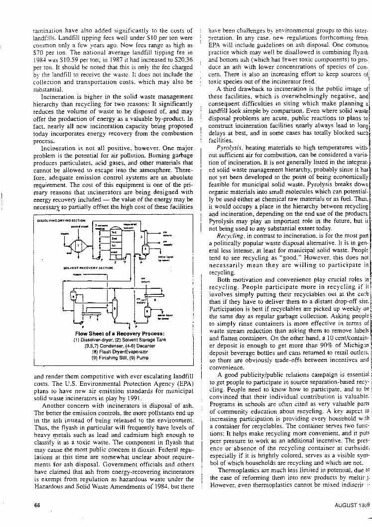
* Flow Sheet of a Recovery Process:
(1) Dissolver-dryer, (2) Solvent Storage Tank (3.5.7) Condenser, (4-6) Decanter
and render them competitive with ever escalating landfill costs. The U.S. Environmental Protection Agency (EPA) plans to have new air emission standards for municipal solid waste incinerators in play by 1991,
Another concem with incinerators is disposal of ash. The better the emission controls, the more pollutants end up in the ash instead of being released to the environment. Thus, the flyash in particular will frequently have levels of heavy metals such as lead and cadmium high enough to classify it as a toxic waste. The component in flyash that may cause the most public concem is dioxin. Federal regu- lations at this time are somewhat unclear about require- ments for ash disposal. Govemment officials and others have claimed that ash from energy-recovering incinerators is exempt from regulation as hazardous waste under the Hazardous and Solid Waste Amendments of 1984. but there
have been challenges by environmental groups to this inter- pretation. In any case, new regulations forthcoming from EP.4 will include guidelines on ash disposal. One common practice which may well be disallowed is combining flyash and bottom ash (which has fewer toxic components) to pro- duce an ash with lower concentrations of species of con-' cem. There is also an increasing effort to keep sources of/
! A third drawback to incineration is the public image of]
these facilities, which is overwhelmingly negative, andl consequent difficulties in siting which make planning a i landfill look simple by comparison. Even where solid waste!
toxic species out of the incinerator feed.
nard>. poor m ment h' the pro mandir floonn&
S i p variou: compat the higl al plas: considt
disposal problems are acute, public reactions to plans to( construct incineration facilities nearly always lead to long' delays at best, and in some cases has totally blocked such/ facilities.
Pyrolysis, heating materials to high temperatures wit'n- out sufficient air for combustion, can be considered a varia- tion of incineration. It is not generally listed in the integrat- ed solid waste management hierarchy, probably since it has not yet been developed to the point of being economically feasible for municipal solid waste. Pyrolysis breaks down organic materials into small molecules which can potential- ly be used either as chemical raw materials or as fuel. Thus, it would occupy a place in the hierarchy between recycling and incineration, depending on the end use of the producrs. Pyrolysis may play an important role in the future, but is not being used to any substantial extent today.
Recycling, in contrast to incineration, is for the most part a politically popular waste disposal altemative. It is in gen-
i era1 less intense, at least for municipal solid waste. People tend to see recycling as "good." However, this does notr necessarily mean they a re will ing to participate i n recycling.
Both motivation and convenience play crucial roles in recycling. People participate more in recycling if i t : involves simply putting their recyclables out at the curb/ than if they have to deliver them to a distant drop-off sire. j Participation is best if recyclables are picked up weekly on i the same day as regular garbage collection. Asking people i to simply rinse containers is more effective in terms of waste stream reduction than asking them to remove labels and flatten containers. On the other hand, a 10 centkontain- er deposit is enough to get more than 90% of MichiganL deposit beverage bottles and cans retumed to retail outlers. so there are obviously trade-offs between incentives and i convenience.
A good publicity/public relations campaign is essential 1 to get people to participate in source separation-based recy- cling. People need to know how to participate, and to be convinced that their individual contribution is valuable. 1 Programs in schools are often cited as verq' valuable paits 5 of community education about recycling. A key aspect fO f. increasing participation is providing every household with $.
a container for recyclables. The container serves two func- tions: It helps make recycling more convenient. and it puts j peer pressure to work as an additional incentive. The pres- 1 ence or absence of the recycling container at curbside, especially if it is brightly colored, serves as a visible sym- e bo1 of which households are recycling and which are not. r
Thermoplastics are much less limited in potential, due 10 3 the ease of reforming them into new products by meltir.?. !. However. even thermoplastics cannot be mixed indiscrir P .:
~
i
i
i with o al of J I cling. ' patibil
At waste includ will b: als w'r by red mater; allude
Prc distini
h.1 a thoug! many Iighte. mater and p been makir, by rec
recyci chy. t sions
hl
amOU!
S312i'
66 AUGUST 1939 :
o this inter- iming from ne common ining flyash ’nts) to pro- .ies of con- 1 sources of
I . . I I C image of
gative. and i
p!anning a solid waste to plans to -ad to long ocked such
tures with- red a varia- 1 he integrat- since it has onomically eaks down i potential- fuel. Thus, i recycling e products. ure. but is
: most pan t is in gen- de. People s does not
i cipate in I i a1 roles in 1 :ling if ir
t the curb )p-off site. weekly on ing people I terms of ove labels Itlcontain- Michigan iil outlets. itives and
; essential ased recy- and to be valuable. able parts aspect to
hold with I two func- f nd it puts ’ The pres- 1 curbside,
ible sym- ire not. ai, due to
i melting. 1 idiscrimi-
t
UST 198:
nantlv. Chemicai incomparlbility resuits in blends with very poor mechanics1 properties. While some types of equip- ment have been developed to process “comingled” piastics. the products are suited only for relatively !ow value. unde- manding uses such as wood and concrete substitutes in flooring. fencing, etc.
Significantly better properties are obtainable if resins of various types can be recovered separateiy, or at least in compatible groupings. This is particularly true for some of the high-value engineering resins. For recovery of individu- al plastics to be economical, however, recycling must be considered in the product design stage. It must be possible.
- PP k a r
I d * 0.91
sink float I
Cnk L -PVC
Illustration of Sink Float Method
with only minimal training, for the people handling dispos- al of junked parts to separate plastic components for recy- cling. Therefore, ease of separation, identification and com- patibility must all be addressed during design.
At the top of the solid waste management hierarchy is waste reduction. Two distinct components are generally included here. The first is producing less material which will be to be disposed of. The second is producing materi- als which contain fewer potentially toxic substances, there- by reducing the threat of air and water pollution when these materials are eventually incinerated or landfilled, as was alluded to in the section on incineration.
Producing less material requiring disposal also has two distinct components. Articles can be made with a smaller amount of material, or they can be made to last longer.
Making articles with less material is relatively common, though not always recognized. Over the last several years many things from bottles to automobiles have gotten lighter, smaller, or both. Often this has meant a switch in materials from heavy glass and steel to lighter aluminum and plastic, and reduced energy consumption has often been a primary motivation. Sometimes, but not always, making an object lighter has also reduced its volume, there- by reducing solid waste disposal burdens. However, these same changes have sometimes added to the difficulty of recycling discarded materials. Thus even within the hierar- chy, the relative merit of product and package design deci- sions can be difficult to assess.
Making articles to last longer accomplishes source
POLLUTION ENGINEERING
reduction by reducing the quantity of goods disposed or as weil as the quantity produced. Although most consumers would probably embrace this ides in principle. in pracrice we have become increasingly a “throw-away” society. The growth of the one-way beverage container resulted at least in part from all the people who did not want to bother with handling returnable bottles. It is often less expensive to replace small appliances than to pay to have [hem repaired when they break. Disposable diapers are much more convenient than reusable ones. We can even buy disposable cameras! PE
References Chandler, W. U., Materials Recycling: The Virtue of
Necessity, Worldwatch Paper 56, Worldwatch Institute. Washington. DC, 1983.
Cheremisinoff, P. N., “High Hazard Pollutants.” Poilu- tion Engineering, February 1989.
Environmental Protection Agency, The Solid Waste Dilemma: Agenda for Action, Background Document, PB 88-251137, Washington, DC, 1988
Environmental Protection Agency, The Solid Waste Dilemma: An Agenda for Action. Background Document, PGB 88-25 1 137, Washington, DC. 1988.
Franklin Associates, Ltd., Characterization of Munici- pal Solid Waste in the United Stares. 1960 to 2000, Franklin Assoc., Ltd.. Prairie Village, 1986.
Huebner, James A., “Automobile Materials Strategy,” in Lai, C.; Yam, K. & Selke. S . eds. Recycled Plastics: Devel- opments and Applications, School of Packaging, Michigan State University, E. Lansing, MI, 1987.
Maczko, J. and Kukla, R., “A Process for Converting MixedKontaminated Scrap into a Marketable Lumber Product,” in Lai, C.; Yam, K. & Selke, S. eds, Recycled Plastics: Developments and Applications, School of pack- aging, Michigan State University, E. Lansing, MI, 1987.
Pettit, C. L. Waste Age, 19(3): 74-80, 1988.
Porter, J., “A National Perspective on Municipal Solid Waste Management,” presented at Fourth Annual Confer- ence on Solid Waste Management and Materials Policy, New York City, Jan. 29, 1988.
Preston, F. and Frank, R.; “Plastic Waste: A Key Issue to a Processor;“ SA Paper No. 890498, Feb. 27 - Mar. 3, 1989, Society Autom. Engrs. Conf., Detroit, MI.
Dr. Nicholas P. Cheremisinoff is employed by E.rxon Chemical Company in Linden, N J . He has an extensive technical background in the manufacture and use of plastics.
Paul Cheremisinoff is a Professor of Environmental Engineering at New Jersey Insti tute of Technology, Newark, NJ. He is an e.rpert in the handling and disposal of solid waste materials.
Both of the men are Registered Environmental Managers.