October 2017 Specification 331001 | 1 SPECIFICATION 331001: WATER MAINS AND APPURTENANCES GENERAL 1.1 DESCRIPTION 1.1.1 The following specification covers the design, installation, inspection, testing, and acceptance of potable water systems. Construction consists of furnishing all labor, equipment, tools, appliances and materials for performing all operations necessary for the construction and installation of water mains and service lines, including all piping, valves, valve boxes, fire hydrants, casings, service lines, appurtenances, complete and ready for operation, as indicated on the construction drawings and described herein. 1.1.2 The Developer/Contractor shall furnish to the County a two-year warranty on the materials, fabrication, and workmanship of any and all pipe and fittings furnished. Warranty period shall commence upon written acceptance of the particular component or appurtenance by the County for ownership and operation. 1.1.3 All pipeline and appurtenance material in contact with potable water must be NSF-61 Certified. 1.1.4 All Construction plans, project submittals and record drawings shall comply with the requirements of both Section 1 and Section 2 of the Hillsborough County Public Utilities Department (PUD) Technical Manual. 1.2 REFERENCE DOCUMENTS • American Association of State Highway & Transportation Officials (AASHTO) • American National Standards Institute (ANSI) • American Society of Mechanical Engineers (ASME) • American Society of Sanitary Engineers (ASSE) • American Society for Testing Materials (ASTM) • American Water Works Association (AWWA) • Florida Administrative Code (F.A.C.), Chapter 62-555 • Florida Department of Transportation (FDOT) • The Hillsborough County Cross Connection Control Program, approved August 6, 1993, in accordance with Rule 62-610.469, F.A.C., with legal authority established in the Hillsborough County Code of Ordinances, Chapter 121 Cross Connection Control and Backflow Prevention • Manufacturers Standardization Society of the Valve and Fittings Industry (MSS) • National Fire Protection Association (NFPA) • NSF International (NSF) • Occupational Safety and Health Administration (OSHA) 1.3 SHOP DRAWINGS AND SUBMITTALS 1.3.1 For County-run projects, shop drawings and related manufacturer's product certification shall be made in accordance with the General and Special Conditions of the Contract for approval prior to
Transcript
October 2017 Specification 331001 | 1
SPECIFICATION 331001: WATER MAINS AND APPURTENANCES
GENERAL
1.1 DESCRIPTION
1.1.1 The following specification covers the design, installation, inspection, testing, and acceptance of potable water systems. Construction consists of furnishing all labor, equipment, tools, appliances and materials for performing all operations necessary for the construction and installation of water mains and service lines, including all piping, valves, valve boxes, fire hydrants, casings, service lines, appurtenances, complete and ready for operation, as indicated on the construction drawings and described herein.
1.1.2 The Developer/Contractor shall furnish to the County a two-year warranty on the materials, fabrication, and workmanship of any and all pipe and fittings furnished. Warranty period shall commence upon written acceptance of the particular component or appurtenance by the County for ownership and operation.
1.1.3 All pipeline and appurtenance material in contact with potable water must be NSF-61 Certified.
1.1.4 All Construction plans, project submittals and record drawings shall comply with the requirements of both Section 1 and Section 2 of the Hillsborough County Public Utilities Department (PUD) Technical Manual.
1.2 REFERENCE DOCUMENTS • American Association of State Highway & Transportation Officials (AASHTO) • American National Standards Institute (ANSI) • American Society of Mechanical Engineers (ASME) • American Society of Sanitary Engineers (ASSE) • American Society for Testing Materials (ASTM) • American Water Works Association (AWWA) • Florida Administrative Code (F.A.C.), Chapter 62-555 • Florida Department of Transportation (FDOT) • The Hillsborough County Cross Connection Control Program, approved August 6, 1993, in
accordance with Rule 62-610.469, F.A.C., with legal authority established in the Hillsborough County Code of Ordinances, Chapter 121 Cross Connection Control and Backflow Prevention
• Manufacturers Standardization Society of the Valve and Fittings Industry (MSS) • National Fire Protection Association (NFPA) • NSF International (NSF) • Occupational Safety and Health Administration (OSHA)
1.3 SHOP DRAWINGS AND SUBMITTALS
1.3.1 For County-run projects, shop drawings and related manufacturer's product certification shall be made in accordance with the General and Special Conditions of the Contract for approval prior to
October 2017 Specification 331001 | 2
purchase or fabrication of the material by the manufacturer. The following items that require shop drawings are brought to the Contractor's attention. This list may not include all items for which shop drawing submittals are required to meet the requirements of the project:
Detail Drawings of all classes of pipe, joints, and fittings. Detail Drawings of restrained and flexible joints, including test reports to confirm thrust
restraint capacities and restraining mechanism application. Pipeline laying schedule, for pipelines greater than 12-inch in diameter, tabulated and
referenced to construction line and grade controls shown on plans, with station, offset and elevations. References shall be provided for pipe fittings, valves, service connections and other important features of the pipeline.
Detail Drawings showing the location and plan views of all Jack and Bore pits (see also Specification 330524), and Horizontal Directional Drill (HDD) pits (see also Specification 330523).
Service Connections. Valves and Valve Boxes. Fire Hydrants and Assemblies. All Appurtenant Items. Contractor’s plan to record and electronically monitor every fusion joint for all fusible
PVC installed. The plan shall include the names of the fusion technicians and certification(s), a description of the equipment to be used, and logged information for each joint shall include proposed heat plate temperatures, and fusion heating/cooling times and pressures, etc.
Contractor’s plans for flushing and testing all supplied water system piping.
1.3.2 Certification and test reports for the materials, manufacturing, and testing of the types of pipe supplied shall be performed and furnished by the pipe manufacturer or supplier in accordance with the latest standards of the industry as referred to in Part 1.2 herein.
1.3.3 Shop drawing submittals for items listed in Appendix B, the Approved Products List, do not require material certification.
1.3.4 Submit a copy of any design exception prior to installation. Design exceptions are issued by the Utility Design Section Manager. Any deviation from these specifications requires a design exception.
1.4 RELATED WORK • All Specifications of Division 03 • All Specifications of Division 33 • Hillsborough County Public Utilities Department Technical Manual • Hillsborough County Utility Accommodation Guide and Rights of Way Use Procedures
Manual • Hillsborough County Transportation Technical Manual
DESIGN
2.1 LINE SIZING CRITERIA
2.1.1 The pipe sizing design criteria for water distribution systems shall as a minimum provide 100% of
October 2017 Specification 331001 | 3
the combined peak hour (maximum day demand rate) plus fire flow. Refer to Section 3 of the Technical Manual for flow criteria and peaking factors.
2.1.2 The allowable minimum service pressure under said design condition shall not be less than 20 psi (pounds per square inch), or 35 psi in a transmission line.
2.1.3 Design flows and method of computation shall be submitted to Development Services Department (DSD) for review by the Public Utilities Department Infrastructure Planning Team at the time of the preliminary plat or site plan submittal, or at the time of the Master Plan submittal.
2.1.4 Minimum pipe size: The minimum pipe diameter for distribution mains not serving fire hydrants or fire hydrant branches shall be four inches. The minimum diameter for distribution mains serving fire hydrants and fire hydrant branches shall be six inches.
2.2 LINE ROUTING
2.2.1 The primary feed for the water distribution system for a residential or commercial subdivision shall be routed within County road right-of-way, A secondary feed may be routed within a utility easement that is dedicated to the County (design exception), only if there is no road right-of-way available. Multiple points of connection may be required in order to minimize service outage in emergencies, repairs, etc., or to improve fire protection and water quality.
2.2.2 The Engineer of Record shall utilize Level “A” SUE work (locates) to design all points of connection. Level “A” SUE shall comply with the definition by ASCE 38-02 as adopted by FDOT.
2.2.3 When the point of connection is an asbestos line, the PUD Utility Coordination Team must be contacted to work out the details at the connection point.
2.2.4 The County requires a project’s off-site infrastructure to be extended beyond the point(s) of connection in the right-of-way to the extent of the development's property. As a minimum, at the entrance to the project, the off-site main extension shall be extended within the right-of-way with a valve and one length of pipe with a restrained cap.
2.2.5 Lines crossing arterial roads, collector roads, and any single-access entry to a subdivision, traditional neighborhood, or commercial driveway shall be cased. The casing shall extend two feet beyond the back of curb/edge of pavement.
2.2.6 All crossings of arterial and collector roads shall be by jack and bore, unless an alternate installation method is approved by Right-of-Way Permitting, or the Jurisdictional Authority for the road.
2.2.7 For projects where the proposed improvement is over existing water lines, all pipe material not meeting the currently approved specifications will require replacement and relocation.
2.2.8 Minimum water line clearance from the property line is five feet. If the line is within an easement, it shall be installed in the center of the easement. See PUD Technical Manual, Section 2.2.4, for additional design requirements for easement installations.
2.3 DEPTH OF COVER
2.3.1 Cover as measured from finished grade to top of the pipeline shall be a minimum of 36 inches for
October 2017 Specification 331001 | 4
pipe diameters up to and including 12 inches. Depth of cover for pipes 16 inches or greater in diameter shall be a minimum of 48 inches. For pipe in FDOT right-of-way, or on County arterial roads the minimum depth of cover shall be 48 inches.
2.3.2 When automatic air release valves are required for pipe diameters up to and including 12 inches, the depth of cover of the entire line must be increased to a minimum of 48 inches (enough to maintain the valve vault flush with the existing or proposed grade). See Specification 331002, Exhibit W-8A through W-8D for ARV details and required depths of bury.
2.3.3 For road improvement projects (road widening, turn lane additions, and storm water improvements, etc.) where the road is currently built, or will be built, over existing water lines, the depth of cover shall be 48 inches (minimum) from top of pipe to the finished road surface. If depth cannot be maintained, or if the existing pipe material does not meet the currently approved specifications, the water line shall be replaced or relocated as determined by the County.
2.4 PROTECTION OF POTABLE WATER SYSTEMS
2.4.1 General There shall be no physical connection between the public water system and any private
water supply, any wastewater or reclaimed water line, or and appurtenance of a wastewater or reclaimed water line that would allow the passage of any sewage, untreated, or polluted water into the potable public water system.
Potable water mains shall not be installed in the same trench with, or within conflict structures containing, reclaimed water mains, sanitary sewers, sanitary force mains, or storm water systems.
When the required horizontal and vertical separations cannot be maintained, a design exception shall be obtained from the Utility Design Section Manager prior to construction commencement.
2.4.2 Horizontal Separation: 2.4.2.1 Water mains shall be laid to provide a minimum horizontal separation of 10 feet from
any existing or proposed wastewater line (gravity or force main). 2.4.2.2 A minimum separation of three feet shall be maintained between potable water mains
and any existing or proposed reclaimed or storm water lines. 2.4.2.3 For service lines a minimum of five feet shall be maintained between a potable water
line and a gravity lateral. 2.4.2.4 All horizontal distances shall be measured face to face.
2.4.3 Vertical Separation: 2.4.3.1 Water mains crossing other pipelines and utilities shall be laid to provide a minimum
vertical distance of 18 inches between the outside of the water main and the outside of the other pipelines/utilities. This shall be the case where the water main is either above or below the other pipelines.
2.4.3.2 Water main crossings below other pipelines should be avoided whenever possible. 2.4.3.3 At crossings, one full length of water pipe shall be located so both joints will be as far
from the other pipelines as possible.
2.5 CROSS-CONNECTION CONTROL
2.5.1 Backflow Prevention Devices/Apparatus shall be installed at all connections to Hillsborough
October 2017 Specification 331001 | 5
County’s water distribution system in accordance with Chapter 121 of the Hillsborough County Code of Ordinances, Part B, Public Utilities (Chapter 121).
2.5.2 All rules, regulations and procedures necessary to administer and enforce the provisions of cross-connection control are established in Chapter 121, which is incorporated herein and made a part hereof.
2.5.3 Backflow Preventers shall be installed in compliance with applicable governing authorities, and in accordance with Specification 331002, Exhibits W-1A through W-1G, and W-2.
2.5.4 Where alternate water sources are present on a property, dual check valves preventers (as a minimum) are required for residential services. Refer to Chapter 121 of the Hillsborough County Code of Ordinances, Part B, Public Utilities.
2.5.5 All Construction Site connections to Hillsborough County’s water distribution system shall be protected by a Backflow Preventer. Backflow Protection shall remain in place until the Development or Project Site water systems have had all of the following items submitted and accepted by DSD. 2.5.5.1 Acceptance through written approval by the Department of Health; 2.5.5.2 Final Inspection by Public Utilities Department employees is completed confirming there
are no potential or existing health or safety conditions present, which could place Hillsborough County in violation of pertinent State Regulations, or could impair, contaminate or in some fashion render Hillsborough County’s water distribution systems unstable, or unsafe.
2.5.5.3 Acceptance of, and placement of the systems under the legal and sanitary control of Hillsborough County’s Public Utilities Department.
2.6 METERS AND METERING ASSEMBLIES
2.6.1 With the exception of dedicated fire service connections, water lines serving commercial and industrial facilities shall be metered. All connections shall be equipped with backflow preventers as shown in Specification 331002, Exhibits Numbers W-1A through W-1H, and as required by Chapter 121. Fire lines serving commercial and industrial facilities must have a reduced pressure detector assembly installed (RPDA) as a minimum. Refer to Specification 331002, Exhibit W-2
2.6.2 Meter size shall be dependent upon flow characteristics. The design Engineer will size the meter or meters subject to approval by PUD Planning Team.
2.6.3 For three-inch and larger meters, a capped tee with a two-inch threaded plug shall be installed immediately downstream of the meter for use as a test port. Refer to Specification 331002 Exhibits W-1C to W-1F for location and orientation of the test port.
2.6.4 A master meter assembly shall be directly accessible by boom truck off the County right-of-way, or by an interior access road that is not blocked by a wall or gate. The access road shall be a minimum width of 12 feet. All access roads shall comply with the Hillsborough County Transportation Technical Manual, and FDOT requirements. 2.6.4.1 The elevation of the concrete slab will be higher than the immediate surroundings area. 2.6.4.2 A five-foot “landscape free” buffer shall be maintained around the meter slab. Do not
mulch around the slab. Do not plant any landscape that will hinder access in the future to the meter assembly.
October 2017 Specification 331001 | 6
2.6.5 Meter assemblies located above ground within vehicle traffic area (parking lot, driveway, or within 15 feet of the edge of pavement or back of curb) shall be protected by a minimum of (4) four bollards. See Exhibit W-1A and W-1B for meters less than 3-inches. 2.6.5.1 For meter assemblies 3-inches and larger, a minimum of six (6) bollards shall be required
and the bollards shall be 6-inch diameter steel pipe, schedule 40, filled with Type I Portland cement, 28 day, 3000 psi concrete. See Specification 331002, Exhibit W-1D through W-1F for details.
2.6.5.2 Bollards shall be painted with one coat of rust prohibitive primer and one coat of Safety Yellow (Fed-Std-595C #13591) or Ultra White (Fed-Std-595C #27925) high grade enamel.
2.6.6 Meter assemblies less than 3 inches may eliminate the 2 inch gate valve at the assembly if all the following criteria are met. 2.6.6.1 An isolation/tapping gate valve is located within 10 feet of the meter assembly. 2.6.6.2 The valve and valve box are located outside of a traffic lane, turn lane, or driveway. 2.6.6.3 A request to eliminate the valve is submitted to DSD with the Construction plans.
2.6.7 The above ground portion of the meter assembly (including the fire service line) shall be painted with an approved paint for above grade piping, fittings and valves found in Appendix B (for NACE Classified C5 –I Environment). The assembly shall be painted with one coat of rust-prohibitive primer and one coat of Safety Blue (Fed-Std-595C #15102) high-grade finish paint.
2.7 SERVICE CONNECTIONS
2.7.1 Water service connections, two-inch and smaller, shall be included as part of the distribution system and consist of: the service line, the corporation stop or a tapping valve, the curb stop, and (for dual service near-side connections) a dual service wye. The builder shall furnish and install water service connections as shown in Specification 331002, Exhibit W-3A through W-3G and as specified herein.
2.7.2 Water service connection taps/service saddles shall be at least 18 inches apart. Service connections 2-inch in size are considered commercial size and require a 2-inch isolation/tapping valve at the point of connection.
2.7.3 Dual service near-side residential connections serving more than one residence are allowed only where reclaimed water service is readily available.
2.7.4 All near-side residential service tubing shall be one-inch polyethylene (HDPE) for both single and dual services. When a dedicated irrigation service meter is installed for an individual residence on the potable water system, either a separate individual line shall be installed for the irrigation service, or a dual service connection shall be installed with the residential meter on the left and the irrigation meter on the right (when facing the house). See Specification 331002, Exhibits W-3A through W-3E.
2.7.5 All far-side residential services shall be single one-inch HDPE tubing with individual service connections. Dual far-side services shall be two, individual one-inch HDPE lines. See Specification 331002, Exhibits W-3A, W-3B, W-3F and W-3G.
2.7.6 Far-side residential service lines (one-inch HDPE tubing) crossing under pavement shall be installed in a two-inch PVC or HDPE sleeve at a minimum depth of three feet below pavement. A
October 2017 Specification 331001 | 7
single three-inch sleeve may be used to encase two, one-inch service lines. The sleeve shall extend a minimum of 24 inches beyond edge of curb and gutter, where present.
2.7.7 Service lines 2 inches and smaller that serve a common area irrigation system are considered non-residential and shall utilize a 2-inch tap and tapping gate valve. The EOR can downsize the service line to 1-inch as determined by their flow calculations. For far-side irrigation service lines, the sleeve crossing under the pavement shall be PVC, 4-inch in diameter. Irrigation lines larger than 2-inch are considered and shall be treated as commercial connections.
2.7.8 A four-inch PVC sleeve shall be used for a two-inch service line, OR where a dual far-side service is required across a cul-de-sac (extra-long sleeve exceeding 50 feet in length).
2.7.9 Service connections shall utilize a tapping or service saddle. Direct taps onto lines is not allowed.
2.7.10 Services two-inch and smaller shall use polyethylene (HDPE) tubing one-inch or two-inch in diameter.
2.7.11 No trees or shrubs shall be planted within five feet of a service meter.
2.7.12 Water service lines and building sewer laterals must maintain a five (5) foot separation per the Florida Plumbing Code. For locations where this separation cannot be maintained, refer to the latest edition of the Florida Plumbing Code.
2.8 FIRE HYDRANT SPACING, LOCATION, AND FLOW
2.8.1 Manufacturing and Industrial Areas: Fire hydrants shall be placed every 300 feet along the right-of-way with a maximum distance of 150 feet to the last lot. The minimum required fire flow shall be 1000 gallons per minute (gpm), provided by either: 1) each hydrant individually, or 2) multiple hydrants flowing simultaneously. The required fire flow shall be determined by the County Fire Marshal’s Office as part of the preliminary plan review process. Hydraulic capacity of the system may be able to provide fire flow above the 1000 gpm minimum, but any required fire flow not provided by the system must be provided onsite.
2.8.2 Commercial and Apartment Areas: Fire hydrants shall be placed every 500 feet along the right-of-way with a maximum distance of 250 feet to the last lot. The minimum required fire flow shall be 1000 gpm, provided by either: 1) each hydrant individually, or 2) multiple hydrants flowing simultaneously. The required fire flow shall be determined by the County Fire Marshal’s Office as part of the preliminary plan review process. Hydraulic capacity of the system may be able to provide fire flow above the 1000 gpm minimum, but any required fire flow not provided by the system must be provided onsite.
2.8.3 Residential Areas: Fire hydrants shall be placed a maximum of 500 feet apart along the right-of-way with a maximum distance of 500 feet to the last lot. The minimum flow from each hydrant shall be 750 gpm.
2.8.4 Other Areas: Fire hydrants shall be placed a maximum of 1000 feet apart, along the right-of-way of rural roads or other areas, as approved by the County on a case-by-case basis.
2.8.5 Location Criteria Hydrants shall be located within one foot of the side lot lines, between adjacent
October 2017 Specification 331001 | 8
properties. Hydrants shall not be located within one pipe length (20 feet) from an intersection corner.
Hydrants shall be a minimum of 24 inches from the edge of right-of-way in areas without sidewalks, and a minimum of six feet from the edge of right-of-way in areas with sidewalks.
The pumper discharge will face the nearest roadway. Refer to Specification 331002, Exhibits W-5A through W-5D for further clarification.
No object(s) may be placed or constructed near a fire hydrant that would obscure the hydrant from full view or would in any other manner hinder the Fire Department from gaining immediate access to the fire hydrant. Per NFPA 1, clearances of seven and one-half feet (7-1/2 feet) in front of and to the sides of the fire hydrant, and four feet (four feet) to the rear of the hydrant must be maintained.
Hydrants shall be a minimum of four feet from back of valley gutter (Miami curb) and two feet from back of upright curb in urban sections. For cul-de-sacs, the fire hydrant shall be positioned at the entrance to the cul-de-sac. If the cul-de-sac exceeds 150 feet (as measured from the intersection) another hydrant shall be installed within the cul-de-sac. See Specification 331002, Exhibit W-6B and W-6C.
For rural sections, FDOT Index 700 Clear Zone Criteria shall be met. Hydrants shall be a minimum of 10 feet from edge of pavement.
Hydrants within paved areas shall be protected by bollards of four-inch (minimum) steel pipe, three feet above and below grade, filled with concrete, set in a cubic yard of concrete, and place as required. Bollards shall be painted Safety Yellow (Fed-Std-595C #13591).
The location of new fire hydrants shall be identified with a blue reflective pavement marker installed on the roadway. The reflective marker shall be located perpendicular to the hydrant, in the center of the lane closest to the hydrant.
Fire hydrants shall be installed as shown in Specification 331002, Exhibits W-5A through W-5D.
2.9 VALVES AND VALVE LOCATION
2.9.1 Isolation Valves Valves and roadway boxes shall be provided for all branch connections (three valves on
a tee, four valves on a cross), fire hydrant stubs, and other locations as required to facilitate operation of the distribution system. All valves shall be installed at the tee, cross, or point of connection. An in-line isolation valve shall be installed wherever a fire hydrant tee is placed.
Valves shall be placed so that the maximum allowable length of water main required to be shut down for repair work shall not be more than 500 feet in commercial, industrial or multi-family residential districts, and 1,000 feet in other areas.
The temporary end of all water main extensions or water mains ending at a project phase shall have a valve and valve box installed with a blow-off assembly.
Valves shall be readily accessible, and located in an area not subject to flooding. Valves shall not be located below the top of bank, within a storm water ditch, or within a swale.
Valves shall not be located in ADA (American with Disabilities Act) ramps, or in curbs.
2.9.2 Air Release Valves (ARVs) ARVs, or fire hydrants, shall be specified at high points where air can accumulate in new
or altered water mains.
October 2017 Specification 331001 | 9
Manual ARVs are preferred, over automatic ARV’s. Automatic ARVs shall not be used in situations where flooding of the ARV manhole
may occur. Air release valves shall not be placed in, or adjacent to driveways. Construction plans and record drawings shall include ARV stationing on both the plan
and profile views. Where automatic ARVs are required, the depth of bury for the line must be increased. It
is incumbent upon the Engineer of Record to ensure the ARV assembly fits within the valve vault, and the vault is installed flush with grade. See Specification 331002, Exhibits W-8B, through W-8D.
2.10 PIPE, FITTINGS, AND APPURTENANCES
2.10.1 Distribution mains outside of residential subdivisions (within the right-of-way or within an easement), or along a collector or arterial road shall be constructed of ductile iron pipe (DIP).
2.10.2 All transmission mains (defined as pipe sizes 16-inch and greater) shall be constructed of ductile iron pipe.
2.10.3 Distribution systems within a subdivision, pipe sized 12 inches and less, shall be either polyvinyl chloride (PVC) or DIP.
2.10.4 No 10 inch or 14 inch pipe shall be used.
2.10.5 All fittings shall be ductile iron and comply with the requirements of Part 3 herein.
2.10.6 All buried ductile iron pipe (including pipe inside of casing), valves, and fittings shall be polywrapped.
2.10.7 The water system is a closed system. The end of pipes shall be capped, or plugged.
2.10.8 Aerial Crossing Pipe shall be ductile iron. Above grade piping shall be Class 53 (minimum).
2.10.9 Restrained Joints Restrained joints shall be installed wherever water main pipe alignment changes
direction. The length of pipe to be restrained and actually restrained shall be noted on the design
and record drawings, respectively. Restrained joints shall be designed with a trench type (per ANSI/AWWA C600 or C605) no higher than Type 3, a safety factor no less than 1.5, and a design pressure no less than 150 psi.
Shop drawings from the manufacturer shall be submitted to and approved by the Engineer prior to actual construction. Refer to Part 1.3.
Thrust blocks are not allowed in the Hillsborough County potable water system. 2.10.9.5 When Exhibit W-7A is used the Design Engineer of Record must fill out the entire
restraint table as applicable for their project.
2.10.10 At all new points of connection, a tee or cross with the appropriate isolation valves shall be installed.
October 2017 Specification 331001 | 10
2.11 BLOW-OFF ASSEMBLY
2.11.1 A blow-off assembly shall be installed on all dead-end mains and at the end of cul-de-sac distribution mains. See Specification 331002, Exhibits W-6A through W-6C for details.
2.11.2 Temporary Blow-off Assembly: Water main extensions at a project phase line shall include a valve and no more than one additional standard length of pipe with a cap and a temporary blow-off assembly, unless a fire hydrant is installed. The temporary blow-off may use a full sized inline valve. Mark plans appropriately for locations.
2.11.3 Construction plan and record drawings shall include blow-off assembly stationing on both the plan and profile views.
2.11.4 Blow-offs shall not terminate in driveways, sidewalks, or any paved surface.
PRODUCTS
3.1 PIPE MATERIAL
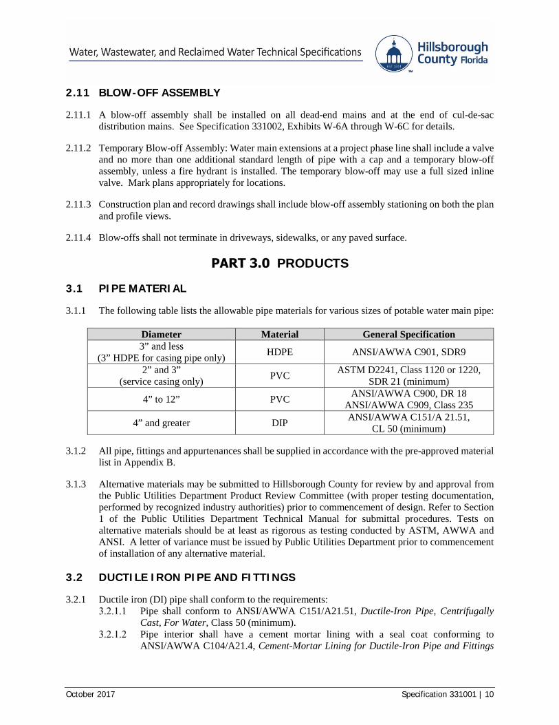
3.1.1 The following table lists the allowable pipe materials for various sizes of potable water main pipe:
Diameter Material General Specification 3” and less
(3” HDPE for casing pipe only) HDPE ANSI/AWWA C901, SDR9
2” and 3” (service casing only) PVC ASTM D2241, Class 1120 or 1220,
SDR 21 (minimum)
4” to 12” PVC ANSI/AWWA C900, DR 18 ANSI/AWWA C909, Class 235
4” and greater DIP ANSI/AWWA C151/A 21.51, CL 50 (minimum)
3.1.2 All pipe, fittings and appurtenances shall be supplied in accordance with the pre-approved material list in Appendix B.
3.1.3 Alternative materials may be submitted to Hillsborough County for review by and approval from the Public Utilities Department Product Review Committee (with proper testing documentation, performed by recognized industry authorities) prior to commencement of design. Refer to Section 1 of the Public Utilities Department Technical Manual for submittal procedures. Tests on alternative materials should be at least as rigorous as testing conducted by ASTM, AWWA and ANSI. A letter of variance must be issued by Public Utilities Department prior to commencement of installation of any alternative material.
3.2 DUCTILE IRON PIPE AND FITTINGS
3.2.1 Ductile iron (DI) pipe shall conform to the requirements: Pipe shall conform to ANSI/AWWA C151/A21.51, Ductile-Iron Pipe, Centrifugally
Cast, For Water, Class 50 (minimum). Pipe interior shall have a cement mortar lining with a seal coat conforming to
ANSI/AWWA C104/A21.4, Cement-Mortar Lining for Ductile-Iron Pipe and Fittings
October 2017 Specification 331001 | 11
for Water. Buried pipe shall have an exterior asphaltic coating in accordance with ANSI/AWWA C151/A21.51.
Joints for ductile iron pipe shall be mechanical or push-on joints, unless otherwise specified herein.
3.2.2 The weight and class designation shall be legibly marked on the exterior surface of every pipe and fitting. Manufacturer’s code or serial number shall be provided on the bell of each pipe joint.
3.2.3 DIP shall be marked with blue stripe/tape in accordance with F.A.C. 62-555.320(21) (b) (3). Adhesive tape shall be two inches wide vinyl, and at least 4.5 mils thick.
3.2.4 Fittings All ductile fittings shall be mechanical joint, and restrained, with a minimum pressure
rating of 250 psi, and shall conform to the requirements of ANSI/AWWA C153/A21.53, Ductile-Iron Compact Fittings for Water Service.
All fittings shall be coated and lined as specified in Part 3.2.1 for ductile iron pipe. All DIP fittings shall bear the approval seal of the National Sanitation Foundation (NSF)
for potable water pipe.
3.2.5 Mechanical Joints Mechanical joints (MJ) consisting of bell, socket, gland, gasket, bolt and nuts shall
conform to ANSI/AWWA C111/A21.11, Rubber-Gasket Joints for Ductile-Iron Pressure Pipe and Fittings.
Bolts shall be high strength low alloy steel, T-head type having hexagonal nuts. Bolts and nuts shall be machined true and nuts shall be tapped at right angles to a smooth
bearing surface.
3.2.6 Push-on Joints: Single seal gasket push-on type joints shall conform to the requirements of ANSI/AWWA C111/A21.11 and shall be as approved in Appendix B for ductile iron pipe.
3.2.7 Restrained Joints Restrained joints (RJ) shall be of the types fabricated by the various pipe manufacturers
and not the type that requires field welding or grooves cut into the pipe barrel for restraint.
The restraining joints for mechanical joint (MJ) fittings and valves shall conform to the requirements of ANSI/AWWA C111/A21.11 and Appendix B. See Specification 331002, Exhibit W-7A.
Restrained joints (both manufacturer supplied and field lock gaskets) shall have the bell of the pipe marked in red. Wrap the bell with vinyl, adhesive red marking tape.
3.2.8 Aerial Crossing Pipe, Hangers, and Accessories Pipe designated for use in aerial crossings and/or attachment to bridge or drainage
structures shall comply with the requirements of ANSI/AWWA C151/A21.51, Class 53 (minimum).
Pipe length shall correspond to “Long Span Pipe”, DIP restrained joint. Pipe joints shall consist of a mechanical joint-flange (MJ-FLG) or a flanged-plain end
(FLG-PE), and flanged-restrained (FLG-RJ). The flange joint shall be equipped with an O-ring gasket.
Flanged joints to be lined per ANSI/AWWA C115/A21.15, Flanged Ductile-Iron Pipe with Ductile-Iron or Gray-Iron Threaded Flanges. Exterior coating shall be field
October 2017 Specification 331001 | 12
applied, color coded blue, and comply with the pre-approved products specified in Appendix B. All exposed threads are to be coated with paint.
Hangers and Accessories a) Anchor bolts shall be Grade 316 stainless steel, installed in accordance with the
construction drawings, and utilizing non-shrink grout. b) Roller stands: Roller stands and roller axles shall be Grade 316 stainless steel. c) Insulated pipe rollers: Pipe support rollers shall be constructed of dielectric synthetic
resin. d) Link seal and sleeve seals shall be modular mechanical type, consisting of
interlocking synthetic rubber links shaped to continuously fill the annular space between the pipe and the wall opening. Links shall be loosely assembled with bolts to form a continuous rubber belt around the pipe with a pressure plate under each bolt head and nut.
e) Hangers: Hangers shall be made in accordance with MSS SP-58, and ANSI/ASME pressure piping code B31.1.
3.2.8.6 Polywrap/Polyethylene Encasement: All buried ductile iron pipe and fittings shall be encased in polyethylene in accordance with ANSI/AWWA C105/A21.5, Polyethylene Encasement for Ductile-Iron Pipe Systems. Polyethylene shall be 8 mils thick.
3.3 POLYVINYL CHLORIDE PIPE AND FITTINGS
3.3.1 All PVC pipe and fittings shall bear the approval seal of the NSF International (NSF) that will remain legible during normal handling, storage, and installation. Pipe color shall be BLUE for all potable water mains.
3.3.2 PVC pressure pipe (4 inches through 12 inches in diameter) shall conform to the requirements of ANSI/AWWA C900 or C909.
It shall have the same O.D. as ductile iron pipe and be compatible for use with ductile iron fittings.
The pipe shall conform to pipe dimension ratio (DR) of 18, shall have a minimum working pressure of 200 psi, and nominal laying length of 20 feet.
3.3.3 All PVC shall be formulated for sunlight exposure and shall pass the impact strength test as described by ASTM D2444, latest revision, using TUP A with impact level of 94 ft.-lbs.
3.3.4 Fittings: Fittings for PVC pipe shall be ductile iron mechanical joint and comply with the requirements of Part 3.2.
3.3.5 Joints All PVC pipe shall have provisions for expansion and contraction provided in the joints. All non-fused joints shall be designed for push-on makeup connection. A push-on joint
shall be an elastomeric gasket bell end coupling manufactured as an integral part of the pipe barrel consisting of an integral wall-thickened expanded bell end section with a ring groove to retain an elastomeric sealing ring of uniform cross-section as pre-approved in Appendix B for PVC pipe.
Restrained Joints: See Specification 331002, Exhibit W-7A and W-7B for restrained joint details. See Appendix B for pre-approved products. The length of pipe to be restrained shall be noted on the Construction Drawings.
October 2017 Specification 331001 | 13
3.3.6 Fusible PVC Pipe shall be provided with plain ends. The ends shall be square to the pipe and free of
any bevel or chamfer. There shall be no bell or gasket of any kind incorporated into the pipe.
Fusible PVC shall be manufactured in a standard 20-foot, 30-foot or 40-foot nominal lengths.
Fusible PVC pipe lengths shall be assembled in the field with butt-fused joints. The Contractor shall follow the pipe supplier’s written guidelines for this procedure, using only demonstrated qualified fusion technicians.
3.4 GASKETS Pipe and fitting gaskets, conforming to ANSI/AWWA C111/A21.11, shall be made of Viton (fluorocarbon elastomer), EPDM (ethylene propylene diene monomer) or SBR (styrene-butadiene rubber). Material selection shall be dependent upon service and soil conditions.
3.5 POLYETHYLENE (HDPE) SERVICE PIPE AND TUBING
3.5.1 Extrusion compound shall comply with the applicable requirements for PE 3608 or 4710, very high molecular weight polyethylene plastic material, as specified in ANSI/AWWA C901, and a cell classification of 345464C (or E) or 445474C (or E) as specified in ASTM D3350. Refer to Appendix B for a listing of pre-approved products.
3.5.2 Tubing shall be 200 psi, Type CTS (copper tubing size).
3.5.3 Standard Dimension Ratio (SDR): The standard dimension ratio for polyethylene tubing provided in Copper Tubing Sizes
shall be nine. The average outside diameter, minimum wall thickness and respective tolerances for any cross section shall be as specified in ASTM D2737.
The standard dimension ratio for three-inch diameter pipe (used as casing pipe only) shall be seventeen for IPS pipe sizes. The average inside diameter, minimum wall thickness, and respective tolerances for any cross-section shall be as specified in ANSI/AWWA C901.
3.5.4 Environmental stress cracking resistance testing shall be performed in accordance with ASTM D1693, Condition C, and shall have no failures during a 5000-hour test period.
3.5.5 Pipe Identification: Polyethylene potable water service pipe or tubing shall be blue in color, or identified with a blue stripe and the words Potable Water at eight-inch intervals. A list of pre-approved materials are given in Appendix B.
3.6 VALVES AND APPURTENANCES
3.6.1 General All valves shall be the manufacturer’s standard design for the service intended and shall
be cast with the manufacturer’s name, year the valve casting was made, and the pressure rating on the body, and if applicable, the valve type, size, and a flow direction arrow.
Valves shall open by turning the operating unit (operating nut or hand wheel) to the left, or counterclockwise, when viewed from the top. The operating nut, or hand wheel, shall have an arrow cast in the metal indicating the direction of opening.
October 2017 Specification 331001 | 14
Only valve types listed are acceptable for use in Hillsborough County. See Appendix B for pre-approved valves.
3.6.2 Gate Valves Gate valves shall be of the resilient seat type meeting the requirements of ANSI/AWWA
C509 or C515, and coated per ANSI/AWWA C550, Protective Interior Coatings for Valves and Hydrants. Two-inch valves shall comply with the intent of ANSI/AWWA C509/C515 and C550.
All gate valves shall be iron body, bronze trimmed, solid wedge, resilient-seated, and shall be equipped with O-Ring type stuffing boxes. a) All gate valve stem nuts shall be bronze. b) All gate valve “gates” shall be fully encapsulated with and fully bonded to the
resilient seat material. c) All gate valve resilient wedges, O-Rings, and gaskets in contact with the potable
water shall be EPDM (Ethylene Propylene Diene Monomer) material. All gate valve bolting materials, excluding joint accessories, shall at a minimum be Grade
304 stainless steel, shall be readily accessible for valve maintenance, shall have square or hexagonal heads and shall be in conformance with the requirements of Section 4.4 of ANSI/AWWA C509/C515.
All gate valves shall be coated with a fusion bonded epoxy coating applied to both the exterior and the interior surfaces prior to assembly of the valves.
All gate valves, when fully opened, shall have an unobstructed waterway diameter equal to or larger than the full nominal diameter of the valve.
Underground gate valves a) These valves shall have non-rising stems and shall be furnished with two-inch square
AWWA operating nuts. b) Valves shall have MJ-RJ ends and shall be furnished complete with joint
accessories. Exposed or above-ground gate valves shall be outside screw and yoke (OS&Y) flanged
joint type with an operating hand wheel. The face-to-face dimensions and drilling shall conform to ANSI B16.10 for Class 125 flanged joint end gate valves.
The minimum design working water pressure shall be: a) 200 psig for three-inch through 12-inch sizes; b) 150 psig for 16-inch through 36-inch sizes.
All gate valves, prior to shipment from the manufacturing facility, shall be tested by subjecting it to a minimum hydraulic pressure equal to twice the specified working pressure.
All gate valves shall be warranted by the manufacturer for a minimum of 10 years.
3.6.3 Tapping Valves, Tapping Sleeves, and Service Saddles Tapping sleeves, tapping crosses, and tapping valves used to make “wet” taps into
existing mains shall be provided and installed at locations shown on the Construction drawings.
3.6.3.2 No size-on-size taps, or direct taps to pipe, are allowed. Tapping Valves
a) Tapping valves shall be mechanical joint outlet, non-rising stem, resilient seat gate valves meeting the applicable requirements of ANSI/AWWA C509/C515 and C550.
b) Tapping valves shall be specifically designed for pressure tapping with sufficient seat opening to allow full diameter taps to be made.
October 2017 Specification 331001 | 15
c) Tapping valves shall be manufactured with an integral tapping flange having a raised lip design in accordance with MSS SP60.
d) All tapping valves shall be coated with a fusion bonded epoxy coating applied to both the exterior and the interior surfaces prior to assembly of the valves.
e) Tapping valves shall be furnished with a combination flange and mechanical joint for connecting the branch to the main.
Tapping Sleeves and Crosses Tapping sleeves shall be SS with wraparound gasket style, MJ split iron units, or
fabricated carbon steel units with a fusion-bonded epoxy coating and outlet seal gaskets, and shall be pressure rated as listed in 3.6.2.8. 1) SS with wraparound gaskets shall be limited for use on all pipes up to 12 inches
in diameter. 2) MJ split iron units shall be limited for use on PVC pipe up to 12 inches in
diameter, and shall not be used on AC pipe. 3) Fabricated carbon steel units with fusion bonded epoxy coating and outlet seal
gaskets shall not be used on AC pipe. The Contractor shall verify the outside diameter of the existing main before ordering
the sleeve. Tapping sleeves shall have an outlet flange per ANSI B16.1, Class 125 standard.
Service Saddles a) Service saddles shall have a ductile iron body, be equipped with double tie straps,
and be suitable for either wet or dry installation. b) The sealing gasket shall be the O-ring type suitable for the applicable service. The
outlet connection shall be FIP threads, 2 inch or less. c) Tie straps and bolts shall be a corrosion resistant alloy steel. d) Service saddles shall be as pre-approved in Appendix B.
3.6.4 Service Connections Corporation Stops
a) Corporation stops from one inch through two inches in diameter shall be brass with machined fitting surfaces in accordance with ANSI/AWWA C800, Underground Service Line Valves and Fittings.
b) The inlet connection shall be male, iron pipe thread (MIP). c) The outlet connection shall be a pack joint or compression joint outlet for copper or
plastic tubing (CTS). All seats and seals must be of an elastomeric material that has verifiable experience in water systems that use chloramines for disinfection. See Appendix B for a list of pre-approved materials and products.
Curb Stops and Meter Valves a) The curb stops shall comply with the requirements of ANSI/AWWA C800. They
shall be ball valve, round way, with check, with lock wing cast on stop body, and operating tee cap to provide for locking the stop in closed position. All seats and seals must be made of an elastomeric material that has verifiable experience in water systems that use chloramines for disinfection.
b) The meter valves shall comply with the requirements of ANSI/AWWA C800. They shall be ball or key valves, with check, with lock wing cast on stop body, and operating tee cap to provide for locking the stop in closed position. All seats/seals must be made of an elastomeric material that has verifiable experience in water systems that use chloramines for disinfection.
c) Meter valves for use with copper or plastic one-inch services and connecting to a
October 2017 Specification 331001 | 16
service meter shall have an inlet connection with a compression joint and an outlet connection with meter swivel nut, aka spud connection. See Appendix B for a list of pre-approved products.
d) Curb stops for two-inch service line shall have an inlet compression joint connection and the outlet shall be female iron pipe thread (FIP). See Appendix B for a list of pre-approved products.
e) Meter Assemblies: Locking curb stops for meter assemblies with meters two inches and smaller shall be female iron pipe thread inlet (FIP) by female iron pipe (FIP) outlet.
Dual Service Branches: Dual service branches shall be solid brass and have CTS compression type connections with internal and external locking device. Pre-approved dual service branches for a one-inch service are listed in Appendix B.
3.6.5 Air Release Valve Assembly Air release valves (ARVs) shall be installed at high points as indicated in Construction
drawings. The locations may be considered approximate. Actual location of ARV on high points shall be determined in the field during construction and reflected in record drawings.
Automatic air release valves shall be of the type that will release air from the line when pressurized and keep air from entering the line when not pressurized. Overall height of the ARV (with vacuum check) shall not exceed 15 inches.
The air release valve assembly shall consist of an ARV with a two-inch inlet; a service or tapping saddle; corporation stop (full port ball valve, with iron pipe (IP) outlet) or a 4 inch tapping valve with an additional 4” isolation gate valve); brass or stainless steel pipe and fittings, and a locking curb stop (IP in/out)
3.6.5.4 The automatic air release valves shall be installed in traffic bearing pre-cast concrete vaults with concrete bottoms. Automatic ARV’s are not to be installed in manholes that are subject to flooding. a) Manual ARVs shall be installed in a traffic bearing box. Pre-approved traffic bearing
boxes are listed in Appendix B. b) See Specification 331002, Exhibit W-8A through W-8D for ARV details.
Valves, fittings, and piping shall be rated for a minimum working pressure of 150 psi, and meet the requirements of ANSI/AWWA C512, Air-Release, Air/Vacuum, and Combination Air Valves for Waterworks Service.
3.6.6 Valve Boxes Cast iron valve boxes with lids shall be provided for all valves installed below ground.
They shall be screw-type adjustable to fit the depth of earth cover over the valve; and designed to prevent the transmission of surface loads directly to the valve or piping. See Specification 331002, Exhibit W-12A.
Valve boxes shall have a minimum interior diameter of not less than 5 inches. Valve box extension shall be installed to reserve a minimum of 50% of the adjustment
for a future extension. Extension sections shall only be screw type cast iron and compatible with the valve box.
The word WATER shall be cast into the valve box lid. The lid shall be painted blue, and shall be constructed so as to prevent tipping or rattling.
All valves locations shall be identified with a concrete valve pad containing a bronze disc embedded in concrete. See Specification 331002, Exhibits W-9A and W-9B.
For valve boxes in pavement, the protective concrete collar ring shall be constructed of
October 2017 Specification 331001 | 17
Type I (3000 psi) concrete. See Specification 331002, Exhibit W-9A.
3.7 METERS AND METER BOXES
3.7.1 Meters The design shall incorporate the requirements of Specification 331002, Exhibits W-1A
through W-1G, and shall be in compliance with Part 2.6 of this specification. Refer to Appendix B for a list of pre-approved products.
All meter testing and their associated lay lengths must meet the applicable ANSI/AWWA C700 series standard.
Meter Accuracy a) Meters two inches and smaller: The meter assembly shall be designed to measure
flow to within an accuracy range of plus or minus 1.5% of normal operating flow, 1-20 gpm, and with flow indication down to 0.25 gpm. (Zero being 100% accurate register reading).
b) Meters three inches and larger: The meter assembly shall meet Class II criteria, designed to measure flow to within an accuracy range of plus or minus 1.5% of actual flow (with zero being 100% accurate register reading) for the designed application.
Meter Assembly Supports: Pipe supports shall be adjustable. Meter Calibration: Each meter shall be provided with proof of calibration prior to
installation. Manufacturers must provide confirmation that independent testing and calibration were performed in accordance with AWWA standards.
Registers shall be permanently and hermetically sealed at the factory. a) Registers shall be direct read or straight read with a center sweep and shall read in
U.S. gallons. b) Digital registers for meters 3 inches and larger that may be used in high-use,
industrial, or commercial applications shall be configured to display the flow totalization only with a 100 gallon multiplier (#x100). Flow measurement is in 100 gallon increments.
All meters shall be weather-resistant, submersible, and able to withstand extended UV exposure without degradation of the performance or the physical integrity of the meter. Meters shall also be able to withstand extended exposure to Hydrogen sulfide gas and periodic exposures to salt water.
One inch and smaller meters shall be compact and have threaded ends. Meters sized 1-½ inches and larger shall have IP or flanged ends.
Polymer clamping devices are not acceptable. All external bolts, nuts, screws and washers shall be 304 or 316 stainless steel. Shear pin bolts shall not be used.
3.7.1.12 Strainers, where necessary, shall be stainless steel. 3.7.1.13 All meters shall have automated meter reading (AMR) compatible registers. The meters
must be modifiable to allow installation of an AMR register. AMR registers must be compatible with all PRC pre-approved meters.
3.7.2 Meter Boxes Meter boxes shall be black in color and of one-piece construction. Boxes shall not exceed
25 pounds in weight. Boxes and lids must pass an AASHTO H-20 (16,000 pound wheel load) test, and the
boxes shall be able to withstand a 200 pound side load.
October 2017 Specification 331001 | 18
Boxes shall have pre-cut pipe entry areas and shall be designed to be securely stackable. Boxes shall be able to take a standard lid size:
a) Single Service: 11-1/8 inches by 18 inches (+ 1/8 inch). b) Dual Service: 14-5/8 inches by 16-5/8 inches (+ 1/8 inch).
Box depth shall be 12 inches, from the face of the lid to the bottom of the box. Boxes and lids shall also comply with Specification 331002 Exhibit W-4.
Dimensional deviations must be approved by the Product Review Committee See Appendix B for a listing of pre-approved products.
3.8 FIRE HYDRANTS
3.8.1 Fire hydrants shall be of the dry barrel, compression-type that closes using line pressure. All hydrants shall comply with ANSI/AWWA Standard C502 Dry-Barrel Fire Hydrants, and shall be both Underwriters Laboratory (UL) listed and Factory Mutual (FM) approved.
3.8.2 Fire hydrants shall open counterclockwise and shall have an arrow clearly cast on the top showing the direction of opening.
3.8.3 Hydrants shall have a 1½-inch pentagon operating nut with an anti-friction mechanism on the thrust collar to reduce operating torque. The operating nut, main stem, coupling and main valve assembly shall be capable of withstanding input torque up to 200 ft-lbs in both opening and closing directions.
3.8.4 The hydrant shall have a factory-filled lubricant reservoir surrounding the working parts in the bonnet. These parts shall be replaceable without removal of the bonnet section.
The reservoir shall have double O-ring stem seals, a thrust nut O-ring seal, and a weather shield designed to protect the operating nut seal.
Grease-lubricated hydrants shall use food grade lubricant.
3.8.5 Fire hydrants shall have two 2½-inch hose nozzles and one 4½-inch pumper nozzle. Nozzles shall use National Standard Fire Hose Threads.
Hose nozzles shall have a minimum 18-inch clearance from their centerline to the bury line. The bury line shall be cast (or otherwise permanently designated) on the lower barrel. The hose nozzle shall be threaded, “O”-ring sealed, and locked into place with a stainless steel locking device.
Hose nozzle caps shall have durable EPDM or neoprene nozzle cap gaskets. Nozzle caps shall be cast with a 1½ -inch pentagon nut for cap removal.
3.8.6 Fire hydrants shall have a breakable safety flange and steel or cast-iron stem coupling located below the break line of the hydrant that allows 360-degree positioning. The safety stem coupling shall be painted with a corrosion-resistant coating. All necessary stem and cotter pins shall be Grade 304 stainless steel.
3.8.7 Fire hydrant main valves shall be a minimum 3/4-inch thickness and 95 durometer EPDM. The main valve shall be fully supported by bronze or epoxy coated upper and lower valve plates. The main valve assembly shall be replaceable by disassembling at the hydrant bonnet flange. Lower stem threads shall be gasket sealed from water intrusion in both the open and closed position for corrosion protection. The bronze seat ring shall be a minimum five-inch inside diameter and shall thread into a bronze ring. The drain valves and outlets shall not be drilled, creating a positively plugged drain system. All wetted, bronze, hydrant parts shall be in accordance with ANSI/AWWA C502, Section 4.4.2.5, Table 1, and meet the following additional requirements:
October 2017 Specification 331001 | 19
A minimum copper content of 79%. Shall not exceed 16% zinc. Shall meet the following yield strength/elongation criteria of 25,000 psi (minimum)/15%
minimum elongation in two-inch (gauge length of sample), or 32,000 psi (minimum)/10% minimum elongation in two-inch.
3.8.8 Fire hydrants shall have a minimum bury depth of three feet six inches to the bottom of the shoe, and the barrel sections shall have a fully assembled six-inch mechanical joint shoe inlet. The preferred bolt configuration in the underground flanging of the shoe and the lower barrel shall be 3/4-inch 304 stainless steel with six full bolts. All internal and external bolts shall be 304 stainless steel.
3.8.9 Fire hydrant shall have a 150 psi working pressure and 300 psi test pressure. Hydrants shall have a maximum 2.0 psi head loss when tested in accordance with ANSI/AWWA C502, Section 5.2.1.
3.8.10 Fire hydrant shall be painted above ground with one coat of rust prohibitive primer and one coat Safety Yellow (Fed-Std-595C #13591) approved high grade brushing enamel. All continuously wetted ferrous metal surfaces in the hydrant shoe, including the lower valve plate, shall be epoxy coated and all other surfaces shall be coated with asphalt varnish as noted in ANSI/AWWA C502, Section 4.13. All hydrants shall be designated “Hillsborough County Specifications” on the low barrel. Fire hydrants shall be AWWA Traffic Models meeting the above stipulations and as pre-approved in Appendix B.
3.8.11 All fire hydrants shall be flow tested and the bonnet color coded in accordance with NFPA 291. All flow test results shall be submitted to Public Utilities Department personnel during final walk-through inspection.
3.9 BACKFLOW PREVENTERS
3.9.1 Backflow Preventers shall be placed on water service connections in compliance with Chapter 121 of the Hillsborough County Code of Ordinances, Part B, Public Utilities 3.9.1.1 The backflow preventer shall be installed in accordance with the Florida Plumbing Code,
and in such a manner as to allow ready access for inspection, in-line repair, removal and replacement without disturbing the structural integrity of the piping system, or the integrity of the shutoff valves used to isolate the backflow preventer.
3.9.1.2 All backflow preventers shall comply with NSF/ANSI 61 Drinking Water System Components – Health Effects.
3.9.1.3 Dissimilar metals shall be separated, as required by the Florida Plumbing Code, utilizing dielectric unions.
3.9.1.4 The size of the backflow preventer shall not be smaller than the size of the meter. In the event the water service connection is not metered, the size of the backflow preventer shall be no smaller than the size of the water service connection itself.
3.9.1.5 All backflow preventers shall be of a horizontal configuration. 3.9.1.6 It shall be the responsibility of the Design Engineer or the Engineer of Record to
determine whether a strainer is required or warranted at the service connection. 3.9.1.7 All backflow prevention assemblies shall be listed in the List of Approved Backflow
Prevention Assemblies published by the University of Southern California Foundation for Cross-Connection Control and Hydraulic Research.
October 2017 Specification 331001 | 20
3.9.2 Reduced-Pressure Principle Backflow Preventer Assembly All reduced-pressure principle backflow preventer assemblies shall meet both the
requirements of ANSI/ASSE 1013 and ANSI/AWWA C511, Reduced-Pressure Principle Backflow Prevention Assembly.
The backflow device body shall be male iron pipe (MIP) end for sizes 3/4 inch to 2 inch.
3.9.3 Double Check Valve Assembly 3.9.3.1 The double check valve assembly shall be a device containing within its structure two
spring-loaded independently operating poppet-type valves mounted in a common body. a) There shall be two gate valves and four test cocks, and shall be designed for
installation in a normal horizontal flow attitude. b) The test cock arrangement will be such that each check valve can be tested without
removal of the assembly from the line. The check valves shall be designed to open under normal flow conditions at a pressure
differential not less than one psi at each check valve and close when the downstream pressure is greater than the supply pressure.
All moving parts shall be corrosion resistant. The device shall also meet the requirements of ANSI/AWWA C510, Double Check Valve Backflow Prevention Assembly, and ANSI/ASSE 1015.
3.9.4 Fire Service Only – Reduced Pressure Detector Assembly 3.9.4.1 All reduced pressure detector assemblies shall meet the requirements of ANSI/ASSE
1047. 3.9.4.2 Valves shall be outside stem and yolk (OS&Y) 3.9.4.3 Refer to 331002, Exhibit W-2 for details of installation.
CONSTRUCTION
4.1 WORK AT HIGHWAY OR RAILROAD CROSSINGS Construction shall not commence for any work along or within County roads, FDOT highways, or railroad crossings until all permits for the pipeline occupancy have been obtained.
4.2 PRECONSTRUCTION PIPE INSPECTION/CERTIFICATION
4.2.1 The Contractor shall obtain from the pipe manufacturer a certificate of inspection to the effect that the pipe and fittings supplied for the project have been inspected at the plant and that they meet the requirements of these specifications.
For County Contracted projects, the Contractor shall submit these certificates to the Project Manager prior to installation of the pipe materials.
For developer projects, the Contractor shall submit these certificates to the PUD Inspection Group prior to the installation of the pipe materials.
4.2.2 Joints or fittings that do not conform to these specifications will be rejected and must be removed immediately by the Contractor.
4.2.3 The entire product of any plant may be rejected when, in the opinion of the County, the methods of manufacture fail to secure uniform results, or where the materials used are such as to produce inferior pipe or fittings.
October 2017 Specification 331001 | 21
4.2.4 For County contracted projects all pipe and fittings shall be subjected to visual inspection at time of delivery and before they are lowered into the trench to be laid.
4.2.5 PVC pipe shall not be off-loaded with chains, wire rope, or other pipe handling implements that may scratch, nick, cut or gouge the pipe. Any scratch or gouge that is greater than 10% of the wall thickness is considered significant and shall be rejected.
4.3 INSTALLATION
4.3.1 The provisions set forth herein shall be applicable to all underground potable piping installations.
4.3.2 All pipe shall be installed at a minimum depth of three feet (36 inches to the top of pipe) below final grade.
4.3.3 All mechanical joints, and connections to pipe, fittings, valves, meters or apparatus shall be installed so as to ensure no negative pressure is placed or potential placed against the joint, or connection, thereby causing a malfunction or failure of the mechanical joint, or connection.
4.3.4 All pipe shall be color coded BLUE. DIP shall be marked with blue stripes/tape in accordance with F.A.C. 62-555.320 (21),
(b)(3). Adhesive tape shall be two-inch wide vinyl, and a minimum of 4.5-mil thick. Polywrap shall be color coded blue or clear. PVC pipe shall be blue throughout the thickness.
4.3.5 It shall be the Contractor’s and Developer’s responsibility to verify all existing conditions and to locate all structures and utilities along the proposed utility alignment in order to avoid conflicts. Where conflicts exist, SUE work shall be coordinated with the facility owner and performed so as to cause minimum interference with the service rendered by the facility disturbed.
4.3.6 Facilities or structures damaged shall be repaired or replaced immediately at the Contractor’s or developer’s expense. The repair or replacement shall be in conformance with current standard industry practices, according to the direction of the owner of such facility and approved by the County.
4.3.7 See Specification 331002, Exhibit W-10 for Jack and Bore details and Exhibit W-11 for Ditch Crossing details.
4.3.8 Directional Drill/Jack and Bore: Where open cut is not practical directional drilling per Specification 330523, or jack and bore per Specification 330524, shall be used. All directional drill, and jack and bore, locations shall be indicated on the Construction drawings, and approval from PUD is required prior to starting construction.
4.3.9 No pipe shall be laid when the trench conditions or the weather is unsuitable for such work.
4.3.10 The water system is a closed system. The ends of pipe shall be capped, or plugged.
4.3.11 Polyvinyl chloride pipe may be damaged by prolonged exposure to direct sunlight. The Contractor shall take necessary precautions during storage and installation to avoid this damage. Pipe shall be stored under cover and sufficient backfill shall be placed to shield it from the sun as the pipe is installed.
October 2017 Specification 331001 | 22
4.3.12 All pipe crossing driveways and landscape areas is to be installed by directional drill unless otherwise noted on the construction drawings. All pipe crossing arterial and collector roads shall be installed by jack and bore.
4.3.13 All Non-metallic pipe shall be installed with two insulated 10 gauge solid copper or copper clad steel core locating wires with color coded coating (blue) attached at 10:00 and 2:00. Wire for direction drill applications shall be copper clad “hard drawn” steel core with a minimum breaking strength of 1000 pounds.
Wires shall be attached using minimum two-inch wide duct tape. Tape shall be at every joint and at four to five-foot spaced intervals.
Locating wires shall terminate four or more inches above the concrete valve pad and shall be folded back inside a three-inch PVC access pipe (see Specification 331002 Exhibit W-12A). A continuity test shall be performed by the Contractor in the presence of the County inspector.
In the case where a valve’s location falls within paved road, wires shall be continuous to the next valve outside pavement.
Wires shall be installed on terminal water lines leading to fire hydrants. Access to tracer wires at the hydrant valve, shall be provided when the hydrant is more than 10 feet from the water main.
4.3.14 When fusible PVC is used, Fusion Technicians must be fully qualified by the pipe supplier to install fusible PVC of the type(s) and size(s) being used. Qualification shall be current as of the actual date of fusion performance on the project.
4.3.15 Excavation, trenching and backfilling shall be in accordance with the requirements of the applicable portions of these specifications. In addition, all underground facility installations shall comply with the requirements of section 5.4 of the Utility Accommodation Guide.
4.4 TRENCH EXCAVATION
4.4.1 All excavations shall be open cut, with banks of trenches kept as nearly vertical as possible and wide enough to allow approximately eight inches clearance on each side of the pipe.
4.4.2 The trench floor shall provide a uniform bearing for each full length of pipe section. Excavate bell holes after trench has been graded. See Specification 331002, Exhibit W-14.
4.4.3 Perform all excavations of whatever substance encountered to the depths shown or indicated on plans.
4.4.4 In the event unsuitable or unstable soil is encountered, remove it to a depth of six inches (minimum) below the bottom elevation of the pipe (12 inches if rock or boulders are encountered) and replace with material meeting AASHTO Soil Classification A-1, A-2, or A-3, as approved by the Project Manager or Engineer of Record. Reference FDOT Standard Specifications for Road and Bridge Construction Section 125-4.
4.4.5 Dewatering: Remove all water from excavations and maintain the excavations free of water while construction therein is in progress. Provide dewatering equipment as necessary to conform to this requirement. Dewatering procedure must meet all regulatory requirements.
4.4.6 Protection of Trees: Trenching shall not take place within the root zone of trees with a trunk
October 2017 Specification 331001 | 23
diameter of 6-inches or larger. The root zone shall be defined as the greater of one) the drip line of the tree or two) a circular zone extending outward from the base of the tree a distance equivalent to 1/2-foot for every inch of trunk diameter as measured 4-1/2 feet above natural grade (see Specification 331002 Exhibit W-13). Exotic nuisance species, such as Brazilian Pepper and Melaleuca, are exempt from this protection.
4.5 HANDLING AND CUTTING PIPE
4.5.1 Every care shall be taken in handling and laying pipe and fittings to avoid damaging the pipe, scratching or marring machined surfaces, and abrasion of the pipe coating both inside and out.
4.5.2 Care should be taken not to let the pipe strike sharp objects while swinging or being off loaded. The pipe shall not be dropped or unloaded by rolling.
4.5.3 Any fitting showing a crack, and any fitting or pipe which has received a severe blow that may have caused an incipient fracture (even though no such fracture can be seen) shall be marked as rejected and removed at once from the work.
4.5.4 In any pipe showing a distinct crack and in which it is believed there is no incipient fracture beyond the limits of the visible crack, the cracked portion, if so approved by PUD, may be cut off before the pipe is laid. The cut shall be made in the sound barrel at a point of at least 12 inches from the visible limits of the crack. All cutting shall be done with a machine adapted to the purpose. All cut ends shall be examined for possible cracks caused by cutting.
4.5.5 Cutting Pipe: The Contractor shall cut pipe by means of an approved mechanical cutter. The cut shall be perpendicular to the longitudinal axis of the pipe and rough ends or spurs will be satisfactorily removed prior to installation and seating.
4.6 FUSION PROCESS
4.6.1 Fusible PVC shall be handled in a safe and non-destructive manner before, during, and after the fusion process and in accordance with this specification and the pipe supplier’s guidelines.
4.6.2 Fusible PVC shall be fused by qualified fusion technicians, as documented by the pipe supplier.
4.6.3 Each fusion joint shall be recorded and logged by an electronic monitoring device affixed to the fusion machine.
4.6.4 Only appropriately sized and outfitted fusion machines that have been approved by the pipe supplier shall be used for the fusion process. Fusion machines must incorporate the following properties/elements: heat plate, carriage, and data logging device.
4.6.5 Other equipment specifically required for the fusion process shall include the following: Pipe rollers used to support the pipe on either side of the fusion machine. A weather protection canopy that allows full machine motion of the heat plate, fusion
assembly and carriage. Fusion machine and maintenance manual shall be kept with the fusion machine at all
times. Facing blades specifically designed for cutting fusible PVC.
October 2017 Specification 331001 | 24
4.7 PIPE LAYING
4.7.1 Pipe shall be constructed of the materials specified and as shown on the drawings.
4.7.2 Cradle: Upon satisfactory excavation of the pipe trench, recesses for the pipe bells and joints (or couplings) shall be excavated by hand digging. When the pipe is laid in the prepared trench, true to line and grade, the pipe barrel shall receive continuous, uniform support and no pressure will be exerted on the pipe joints from the trench bottom.
4.7.3 Cleanliness: The interior of the pipes shall be thoroughly cleaned of all foreign matter before being gently lowered into the trench and shall be kept clean during laying operations by means of plugs or other approved methods. During suspension of work for any reason at any time, a suitable stopper shall be placed in the end of the pipe last laid to prevent mud or other foreign material from entering the pipe.
4.7.4 Gradient Lines shall be laid straight, and depth of cover shall be maintained uniform with respect
to finish grade, whether final grading is completed or proposed at time of pipe installation. When a grade or slope is shown on the Construction Drawings, means shall be used by the Contractor to assure conformance to required grade.
Any pipe which has its grade or joint disturbed after lying shall be taken up and re-laid.
4.7.5 Pipe/Joint Deflection: Whenever it is desirable to deflect pipe, the amount of deflection shall not exceed the following:
For pipe joints: 75% of the maximum limit as specified in AWWA C600 (for Ductile iron) or AWWA C605 (for PVC), or the manufacturer’s recommendation, whichever is less.
For PVC pipe: 75% of the maximum limit as specified in AWWA C605, or the manufacturer's recommendations, whichever is less.
4.7.6 Rejects: Any pipe or fittings defective due to interior or exterior damage shall be immediately removed and replaced with sound pipe or fitting at the Contractor's expense.
4.7.7 PVC: All PVC water mains shall have electronic locator wires in accordance with Part 4.3.12, herein. The wires shall be continuous between valves.
4.7.8 Any section of pipe already laid which is found to be defective or damaged shall be replaced with new pipe without additional cost to the County.
4.7.9 Installation of PVC pipe and fittings shall be in accordance with the installation requirements established by the manufacturer and AWWA M23.
4.8 INSTALLING JOINTS
4.8.1 The joints of all pipelines shall be assembled in straight alignment and made tight. The particular joint used shall comply with the requirements of Part 3.2 and 3.3. For County contracted projects, the particular joint used shall be reviewed and approved by the Engineer prior to installation.
4.8.2 Ductile iron pipe and fittings can only be pushed when using a restrained joint system that does not allow the spigot to contact the bell shoulder. Pipe may be pulled using restrained joint pipe or
October 2017 Specification 331001 | 25
restraining gaskets as restraints.
4.8.3 Restraining gaskets must never be pushed; nor should pipe be homed all the way to the bell shoulder.
4.8.4 All joints on PVC C905 pipe installed by open cut shall be photographed showing proper insertion, axial deflection, and joint location. At a minimum, the Contractor shall provide a digital photograph of each push on and restrained joint using the following criteria.
The photograph shall display the date, time and location (either station and offset, or GPS X-Y coordinates). This information can be electronically “marked” on the photo; or physically marked on the pipe; or a “white” board can be used with the information displayed.
The picture resolution shall be no less than three megapixels, set at 2048 by 1536, ISO 200, and fine/superfine to produce a minimum 1.5 megabyte size photo file.
Every photo shall be framed in such a manner that its entire width shall be taken up by the joint, and two feet of pipe on each side of the joint.
The Manufacturer’s installation reference mark must be visible and centered in the photograph.
The photo file format shall be in JPG. The complete set of photos shall be submitted to the Inspector in DVD format.
4.8.5 Mechanical Joints: All types of mechanical joint pipes shall be laid and jointed in full conformance with manufacturer's recommendations. Torque wrenches set as specified in ANSI/AWWA C111/A21.11, shall be used; or spanner type wrenches not longer than specified therein may be used with the permission of the County. Impact wrenches shall not be used.
4.8.6 Push-On Joints: Push-on joints shall be made in strict compliance with the manufacturer’s recommendations.
Lubricant shall be an inert, non-toxic, water soluble compound. Insert the spigot end into the bell so that it is in uniform contact with the gasket. For PVC pipe, push the spigot until the reference mark on the spigot end is flush with
the end of the bell. If the reference mark is not visible after assembly, the joint is to be cut out and reassembled.
For DIP, push the pipe until the reference mark on the spigot end disappears into the bell.
4.8.7 Joint Compounds: Sulfur based joint compounds shall not be used.
4.8.8 Restrained Joints shall be provided at all changes in direction, and size changes, of all mains. All pipe and fitting joints shall be restrained as shown on the Construction Drawings, or
where in the opinion of the Design Engineer, settlement or vibration is likely to occur. All restrained joints shall be installed in accordance with manufacturer’s
recommendations. All restrained joints (manufacturer supplied or field lock gaskets) shall have the joint bell
marked in red.
4.9 INSTALLING APPURTENANCES
4.9.1 Valves and Valve Boxes Valves: Valves shall be carefully inspected, opened wide and then tightly closed and the
various nuts and bolts shall be tested for tightness, on site, prior to installation.
October 2017 Specification 331001 | 26
a) Special care shall be taken to prevent any foreign matter from becoming lodged in the valve seat.
b) Any valve that does not operate correctly shall be immediately removed and replaced by the Contractor.
Valves installed below ground shall be identified with a bronze disc embedded in concrete to identify potable water valves (see Specification 331002, Exhibits W-9A and W-9B).
Concrete Valve Pad: Valve boxes outside of paved areas shall be cast in a 3000-psi concrete slab, two-foot by two-foot square and six-inch (minimum) thick. See Specification 331002, Exhibit W-9B for unpaved installations.
Valve Boxes: Valve boxes shall be carefully centered over the operating nuts of the valves so as to permit a valve key to be fitted easily to the operating nut. a) Valve boxes shall be set to conform to the level of the finished surface and held in
position by a ring of concrete placed under the support flange as shown on the Construction Drawings. See Specification 331002, Exhibits W-9A and W-9B.
b) The valve box shall not transmit surface loads to the pipe or valve. c) Care shall be taken to prevent earth and other material from entering the valve box. d) Any valve box which is out of alignment or whose top does not conform to the
finished ground surface shall be dug out and reset. e) Before final acceptance of the work, all valve boxes shall be adjusted to finished
grade and valve box extensions shall be installed to reserve a minimum of 50% of the adjustment for future extension. Extension sections shall be threaded/screwed cast iron.
f) The operating nut should not exceed 36 inches below finished grade. However, if conditions require that the operating nut exceeds 36 inches, then an extension, mechanically attached to the valve, shall be added, and the top of the extension shall not exceed 12 inches below finished grade. See Specification 331002, Exhibit W-12B.
g) The valve boxes shall be provided with covers marked “WATER” and shall be so constructed as to prevent tipping or rattling. The valves shall be identified with a bronze disc embedded in concrete.
h) Valve boxes shall not be installed in ADA ramps or in curbs.
4.9.2 Air Release Valve Assemblies Construction plans and record drawings shall include air release valve stationing on both
the plan and profile views. The locations of ARVs indicated on Construction plans are approximate. The actual
placement of the air release valves shall be determined in the field and shall be located at the high points as established during installation of the water main and as approved by the Project Manager.
Automatic air release valves shall be installed in a shallow manhole not subject to flooding, as shown in Specification 331002 Exhibit W-8B through Exhibit W-8D.
Manual ARVs shall be installed as shown in Specification 331002 Exhibit W-8A. The Contractor shall furnish and install at no additional cost to the County all necessary
fittings to make adjustments in the field for the installation of air release valves at all high points.
4.9.3 Blow-off Valve Assemblies The Contractor shall furnish and install blow-off valve assemblies as shown on the
October 2017 Specification 331001 | 27
Construction Drawings. The locations shown are approximate. The actual placement of the blow-off valve shall
be determined in the field and shall be located at the low point or end of the pipeline as established during installation of the water main and as approved by the Project Manager.
4.9.4 Fire Hydrants The fire hydrant break flange shall be installed 6 inches above grade. All fire hydrants shall be flow tested and the bonnet color coded in accordance with
NFPA 291. All flow test results shall be submitted to PUD personnel during final walk-through inspection.
4.9.5 Water Meter Assemblies: 4.9.5.1 Water meter assemblies shall be installed in-accordance with Specification 331002,
Exhibit W-1A through W-1H, and part 2.6. 4.9.5.2 Meter assemblies less than 3 inches may eliminate the 2 inch gate valve at the assembly
if all the following criteria are met. An isolation/tapping gate valve is located within 10 feet of the meter assembly. The valve and valve box are located outside of a traffic lane, turn lane, or driveway.
4.9.5.3 All backflow assemblies or devices must have ASSE approval, and shall be a reduced pressure device as listed on the approved list of the University of South California Foundation for Cross Connection and Hydraulic Research.
4.9.5.4 Fire Service only lines must be installed with a Reduced Pressure Detector Assembly meeting the requirements of Specification 331002, Exhibit W-2.
4.10 WATER SERVICE CONNECTIONS
4.10.1 The Contractor shall furnish and install water service connections as shown on the Construction Drawings or as directed by the County as dictated by actual field conditions. Water service connections shall include service lines, corporation stops and curb stops as defined in Part 2 and Part 3, herein. Dual service near-side connections servicing more than one residence are only allowed where reclaimed water service is available.
4.10.2 Meters installed in residential areas within a meter box shall be installed plumb and level, and positioned facing the lot served. The meter valve depth shall be six (6) inches, plus or minus one (+1) inch, below final grade. A two (2) by two (2) inch temporary identification stake shall be placed adjacent to the meters with a final grade line clearly marked on it.
4.10.3 Service Box Location: The developer is required to clearly identify the location of the curb stop and future service connection (see Specification 331002, Exhibit W-3A)
Temporary identification: During construction, the location may be temporarily identified with a two-inch by two-inch by 18-inch wood stake with the top painted blue and marked with the lot(s) number to be served, and shall clearly show the final grade line.
Permanent identification: When the roadway is complete, the Developer shall mark the roadway curb indicating the location of the curb stop and water service connection by cutting a W into the curb.
4.10.4 Service connections shall utilize a tapping or service saddle. Direct taps of lines is not allowed.
4.10.5 Water service lines and building sewer laterals must maintain a five (5) foot separation per the
October 2017 Specification 331001 | 28
Florida Plumbing Code. For locations where this separation cannot be maintained, refer to the latest edition of the Florida Plumbing Code.
4.11 POLYETHYLENE TUBE ENCASEMENT/POLYWRAP
4.11.1 All buried ductile iron pipe, valves, and fittings, including ductile pipe inside of a casing, shall be polywrapped. Installation of polyethylene tube encasement shall be in accordance with Method A of ANSI/AWWA C105/A21.5 and as specified herein.
4.11.2 Raise a length of pipe at the side of the trench to a height of about three feet above ground level by means of hoisting equipment and a pipe sling or tongs.
4.11.3 Using a precut length of polyethylene tubing, two feet longer than length of pipe to be covered, slide plastic tubing over spigot end of the pipe up to the pipe sling or tongs. Bunch the excess of the plastic tubing near the sling or tongs.
4.11.4 Lower the pipe into the trench, joining the lowered length of pipe with that already in place. Shallow bell holes at the pipe joints must be made to facilitate overlapping of the polyethylene at the pipe joints.
4.11.5 Raise bell end of the pipe mechanically or by hand, clear of trench bottom. Slide plastic tube along balance of pipe length to the pipe bell. Leave surplus bunched at the bell for subsequent covering of the joint. Approximately one foot of surplus should be provided at each end of pipe.
4.11.6 To cover the joined pipe joint pull the plastic tubing from the preceding length of pipe over the bell end of the pipe, fold around the spigot end of new pipe section and wrap with three circumferential turns of 1-1/2 inch wide polyethylene tape to seal and hold the film in place.
4.11.7 Pull the bunched polyethylene tubing on the new pipe barrel near spigot end over the first polyethylene wrap until it covers the joint, neatly folded behind the bell, seal and hold in place by three circumferential turns of 1-1/2 inch wide polyethylene adhesive tape. Use red tape around restrained joints.
4.11.8 The polyethylene film covering the pipe will be loose. Excess material should be neatly drawn up around the pipe barrel, folded into an overlap on top of the pipe and held in place by means of pieces of the plastic tape at approximately three to five-foot intervals.
4.11.9 Repair any rips, punctures or other damage to the polyethylene with tape or by cutting open a short length of tube, wrapping it around the pipe and securing with tape.
4.11.10 Fittings such as pipe bends shall also be covered by use of the plastic tubing and plastic adhesive tape in much the same manner as the pipe.
4.11.11 Irregular-shaped appurtenances shall be covered by splitting a suitable length of the polyethylene tubing and using the resulting flat sheet with plastic tape to effect the covering of such items.
4.12 BACKFILL/COMPACTION
4.12.1 Backfilling and compaction shall be conducted in a manner as to preclude subsequent settlement and provide adequate support for the surface treatment, pavement, pipelines, or structures to be
October 2017 Specification 331001 | 29
placed thereon. All trenches shall be prepared per the requirements of Part 4.4. Also refer to Specification 331002 Exhibit W-14.
4.12.2 Backfill and bedding material shall be common fill material free from organic matter, muck or marl, and rock exceeding 2-1/2 inches in diameter, and shall not contain broken concrete, masonry, rubble or other similar materials. When unstable or unsuitable material is encountered replace with AASHTO soil classification A-1, A-2, or A-3.
4.12.3 Method of Compaction: The Contractor shall adopt compaction methods which will produce the degree of compaction specified herein without damage to the new or existing facilities. The degree of compaction specified in the following shall be considered the minimum allowable.
4.12.4 Backfilling Procedures: The backfilling procedures outlined in the following shall be for water mains and related structures. The backfilling shall be done in three stages as follows:
In the first stage, the Contractor shall provide adequate compacted fill beneath the haunches of the pipe, using mechanical tampers suitable for this purpose. This compaction applies to the material placed beneath the haunches of the pipe and above any bedding material. Fill compacted by mechanical compactors shall be placed in six-inch layers and thoroughly tamped over the entire surface.
In the second stage, the Contractor shall obtain a well-compacted bed and fill along the sides of the pipe and to a point of at least one foot above the top of the pipe. The width of backfill and compaction to be done under this second stage shall be the width of the portion of the trench having vertical sides; or, when no portion of the trench has vertical sides, it shall be to a width at least equal to three the outside diameter of the pipe. Material to be placed in six-inch layers (loose thickness).
In the third stage, the remainder of the trench shall be backfilled with suitable material in layers not to exceed 12-inch loose thickness and compacted.
4.12.5 Compaction Density: The trench backfill density for all stages shall be as provided as follows: Right-of-way line to right-of-way line, including all structures and railroad crossings:
Compaction shall be 98 % of the maximum density as determined by AASHTO T-180 (ASTM D1557 - Modified Proctor) with no tolerance.
For outside of the right-of-way (but within maintenance easements): Compaction shall be 95% of the maximum density as determined by AASHTO T-180 (ASTM D1557 - Modified Proctor) with no tolerance.
4.12.6 Compaction Test Requirements Compaction test results shall be submitted for all work. Results of compaction tests must meet minimum requirements prior to proceeding with
the next stage of the work. For developer projects, one complete set of all test reports shall be submitted with the
as-built package to the Site Engineering Review Section upon project completion. For County run projects, one complete set of all test reports shall be submitted with the
as-built package to the Project Manager upon project completion. The Contractor shall employ an independent testing laboratory, acceptable to the County
and pay for all required tests. The laboratory shall submit one copy of the certified test reports, after testing in each
phase, to the Construction Services Section in the Development Services Department, or the County Project Manager (as applicable), for approval.
In the second and third stage of backfilling, density tests shall be made every one foot
October 2017 Specification 331001 | 30
vertically, staggered every 200 feet (minimum) horizontally. There shall be a minimum of one test (per vertical foot) between structures, and a minimum of one test per day.
4.13 TEMPORARY WATER SERVICE FOR CONSTRUCTION
4.13.1 The provisions set forth herein shall be applicable to all construction projects. The Developer/Contractor shall be responsible to submit a temporary water plan (Plan). The Plan shall describe how water will be provided, and the type of meter and backflow assembly that will be installed for construction needs and, if applicable, fire demand. It shall include the maximum peak hour flow which will be required prior to acceptance for occupancy.
For County Projects, the Plan shall be submitted to the Project Manager along with the required construction plans.
For Developer projects, the Plan shall be submitted to the Development Services Department along with the required construction plans.
4.13.2 Connections to Hillsborough County’s distribution system exclusively for construction activities shall be supplied using a temporary construction backflow assembly or a hydrant meter assembly. 4.13.2.1 Construction Backflow Assembly - For supply lines 6 inches and greater an appropriate
temporary construction backflow assembly will be installed and comply with all the installation/connection requirements listed in 4.13.4. Private sources, such as wells, may also be acceptable to the County.
4.13.2.2 Hydrant Meter Assembly - Refer to the Hillsborough County webpage under Businesses/Land development/Site & Subdivision to apply for the installation of a temporary hydrant meter assembly.
4.13.3 Temporary Construction Backflow Assembly: An appropriate sized temporary backflow assembly will be furnished, maintained and installed at the construction site by the Developer/Contractor. Connections to the Hillsborough County distribution system shall conform to Part 2.5. The RPZ must be of an approved model. Calibration certification will be required for the backflow assembly.
4.13.4 When flow demand necessitates the use of a six-inch supply line, the following criteria shall apply. The temporary construction backflow assembly shall be placed along the right-of-way
on the primary feed for the water distribution system of any proposed development. The assembly shall be a maximum of 250 feet from the first lot. See Specification 331002, Exhibit W-1F for backflow assembly and Exhibit W-1H for meter installation notes.
Hydrostatic and Leakage Testing: The primary feed line from the point of connection including the backflow assembly will be cleaned (pigged and flushed) and tested as described in Part 4.15.
Disinfection: The primary feed line from the point of connection up and including the backflow assembly shall be disinfected and receive the required approvals and clearances prior to placing the backflow assembly in service. Disinfection shall be in accordance with Part 4.16.
Pipe and Fittings a) Above ground pipe shall be flanged ductile iron. The pipe barrel shall conform to the
requirements of ANSI/AWWA C151/A21.51, Class 53, with cement lined interior. b) All above ground ductile fittings shall be flanged joint with a minimum pressure
rating of 250 psi, and shall conform to the requirements of ANSI/AWWA C110/A21.10 or C153/A21.53.
c) Underground pipe shall comply with the requirements of Part 3.2 or 3.3.
October 2017 Specification 331001 | 31
Requirements: For County projects, the Contractor shall furnish and be responsible for the proper installation of the temporary construction backflow assembly. For Developer projects, the Developer shall furnish and be responsible for the proper installation of the temporary construction backflow assembly. PUD will be responsible for the inspection of the backflow prevention device.
4.13.5 Removal of Temporary Construction Assembly: After the entire development water distribution system has been installed, cleaned, pressure tested, disinfected, and the requirements of part 2.5.4 have been met, the Contractor shall remove the assembly as directed by Hillsborough County PUD.
4.14 FLUSHING AND CLEANING
4.14.1 All mains shall be cleaned and flushed to remove all sand and other foreign matter. The Contractor shall be responsible for developing a flushing plan to be submitted to the
Engineer of Record for approval with the shop drawings. The flushing plan must be submitted with the “temporary water plan” listed in Part 4.13.1.
The Contractor shall dispose of all water used for flushing without causing a nuisance or property damage.
Any permits required for the disposal of flushing water shall be the responsibility of the Contractor.
4.14.2 Flushing water used by the Contractor shall be taken from an approved metered source. Flushing water shall be at Contractor's expense.
4.14.3 Pipeline shall be cleaned with a "pig", of an appropriate material for the pipeline to be cleaned, so as not to damage the interior lining of the pipeline. Contractor shall be responsible to install and remove appropriate connections to accomplish the required pipeline "pigging".
4.14.4 Temporary plugs or caps shall be installed on new mains until the pressure and leakage tests are completed. Upon satisfactory completion of the tests the caps or plugs shall be removed and the connections made to the existing mains.
4.15 HYDROSTATIC AND LEAKAGE TEST
4.15.1 Water mains shall be tested in sections between valves. The total length of pipe for any single test shall not exceed 2,000 feet. Testing shall be done immediately after installation and backfilling has been completed.
4.15.2 The piping shall be tested in sections, thereby, testing each valve for secure closure.
4.15.3 The mains shall be tested in accordance with, the latest revision of AWWA C600 (for Ductile Iron) and C605 (for PVC) under an average hydrostatic pressure of not less than 150 psi, using a 300 psi gauge, for a minimum of two hours. Pressure shall be maintained until all sections under testing have been checked for evidence of leakage.
4.15.4 While the system is being filled with water, air shall be carefully and completely exhausted. If permanent air vents are not located at all high points, the Contractor shall install corporation stops or fittings and valves at such points so the air can be expelled as the pipe system is slowly filled.
4.15.5 The test pressure shall not vary by more than five psi for the duration of the test. The rate of loss
October 2017 Specification 331001 | 32
shall not exceed that specified in sections 4.15.13 or 4.15.14. Visible leaks shall be corrected regardless of total leakage shown by test.
4.15.6 All pumps, gauges and measuring devices shall be furnished, installed and operated by the Contractor; and all such equipment, devices and their installation shall be approved by the County Inspector.
4.15.7 All water for testing and flushing shall be potable water provided by the Contractor, no cost to the County, from a source approved by the County. Flow velocity during line filling should not exceed 2 feet per second (fps).
4.15.8 The quantity of water used for testing, which shall be compared to the allowable quantity, shall be measured by pumping from a calibrated container approved by the County Inspector.
4.15.9 All restrained sections of the buried main shall be completely backfilled before such sections are tested.
4.15.10 All pressure lines shall be tested. All pressure and leakage testing shall be done in the presence of the County Inspector and the Engineer of Record or his designated representative. Pressure and leakage testing is considered a “hold” point and requires the sign off of the County Inspector.
4.15.11 When leakage occurs in excess of the specified amount, the defective pipe, pipe joints or other appurtenances shall be located and repaired at the expense of the Contractor. If the defective portions cannot be located, the Contractor, at his own expense, shall remove and reconstruct as much of the original work as necessary to obtain a water main within the allowable leakage limits upon retesting.
4.15.12 If the Contractor elects to perform hydrostatic testing against valves in an existing distribution system, he does so at his own risk and will bear the cost of any damage to the existing valve, piping system, private or public property, or the new pipeline under test.
4.15.13 Allowable Limits for Leakage in Ductile Iron Pipe The hydrostatic pressure test shall be performed as hereinabove specified and no installation, or section thereof, will be acceptable until the leakage is less than the number of gallons per hour as determined by the formula:
L = SD(P)½ 148,000 in which: L = Allowable leakage, in gallons per hour S = Length of pipe in feet being tested D = Nominal diameter of pipe, in inches P = Average test pressure during the test, in psi
Water shall be supplied to the main during the test period as required to maintain the test pressure as specified.
The quantity used, which shall be compared to the previous allowable quantity, shall be measured by pumping from a calibrated container. A 5/8-inch meter installed on the discharge side of the pump may be used to measure the leakage for large mains when
October 2017 Specification 331001 | 33
approved by the County Inspector. All hydrostatic leakage tests shall be recorded on the form(s) attached in Part 5.
4.15.14 Allowable Limits for Leakage in PVC Pipe The hydrostatic pressure test shall be performed as hereinabove specified and no installation, or section thereof, will be acceptable until the leakage is less than the number of gallons per hour as determined by the formula:
(1) Q = LD(P) ½ OR (2) Q = ND(P) ½ 148,000 7,400 in which: Q = Allowable leakage, in gallons per hour N = Number of joints in the tested line (pipe & fittings) L = Length of pipe section being tested, in feet D = Nominal diameter of pipe in inches. P = Average test pressure during the test, in psi NOTE: Equation (2) is for gasketed pipe in 20-foot lengths.
Water shall be supplied to the main during the test period as required to maintain the test pressure as specified.
The quantity used, which shall be compared to the previous allowable quantity, shall be measured by pumping from a calibrated container. A 5/8-inch meter installed on the discharge side of the pump may be used to measure the leakage for large mains when approved by the County Inspector. All hydrostatic leakage tests shall be recorded on the form(s) attached in Part 5.
4.16 DISINFECTING WATER SYSTEMS
4.16.1 After completion of pressure testing as described in Part 4.15, the Contractor shall disinfect all pipe and fittings installed in the system and receive the required approvals and clearances prior to placing the system in service.
4.16.2 The disinfection shall be accomplished in accordance with the latest applicable provisions of ANSI/AWWA C651, “Disinfecting Water Mains”, all appropriate approval agencies and the County PUD “Procedures for Water Main Cleaning, Disinfection, and Bacteriological Testing.” See APPENDIX C for a copy of the PUD procedure. Forty-eight hours advance notice shall be provided to the County Department of Health and the PUD Governmental Laboratory prior to disinfection procedures start.
4.16.3 Care shall be taken to provide disinfection of the entire system. After disinfection, the line shall be thoroughly flushed until water samples show a chlorine content equal to or less than the existing system.
4.16.4 Temporary plugs or caps shall be installed on disinfected mains until the connections are made to the existing water mains.
4.17 CONNECTION TO EXISTING WATER MAINS
4.17.1 Connections to existing potable water pipelines shall be made as shown on the Construction
October 2017 Specification 331001 | 34
Drawings. At all new points of connections, a tee or cross with the appropriate isolation valves shall be installed. Coordination between the County and the Contractor shall be required in order to accomplish this task. The Contractor shall supply connection, procedure, and customer notification schedules to the County, for approval, two weeks prior to the proposed connection date.
4.17.2 All connections to existing water mains shall be made under the direct supervision of Hillsborough County PUD.
4.17.3 Valves on existing mains shall be operated by Hillsborough County PUD personnel or under their direct supervision.
4.17.4 When service must be interrupted to existing customers during construction: The Contractor shall provide three days’ notice to the Hillsborough County PUD. The Contractor or developer shall be required to notify existing customers as directed by
PUD. The Contractor shall be ready to proceed with as much material preassembled as possible
at the site to minimize the length of service interruption. Such connections may be made at night to minimize effects. No customer shall be without service for more than six hours.
PUD will postpone a service cut-off if the Contractor is not ready to proceed on schedule.
4.17.5 Taps smaller than six inches (for single connections or distribution systems) to transmission mains 16 inches or larger are not allowed.
In areas where there is no reasonable alternative for providing service, the County may approve a six-inch minimum size connection which reduces down to a four-inch pipeline configured for a future parallel distribution system for additional services.
The connection shall include a tapping saddle, an isolation valve at the point of connection, a minimum four-inch tee to allow for expansions, and isolation valves on each extension.
4.17.6 If a tee and isolation valve cannot be cut in then the following procedures shall be followed. Tapping a Water Main 4.17.6.1 No size on size taps are allowed.
The Contractor shall submit a request to the Service Availability Team, Customer Service Section, of the Hillsborough County PUD to schedule a tap and pay the appropriate tapping fee. The request shall be made a minimum of 48 hours prior to proposed tie-in to the water main.
The Contractor shall furnish, install and pressure test the tapping sleeves and valves to existing water mains.
For all taps up through 12 inches, County PUD personnel will furnish the necessary tapping machine and tools and will perform the tap.
For taps larger than 12 inches, the Contractor shall furnish the tapping machine and tools and shall perform the tap under PUD supervision. All taps shall be witnessed by the County Inspector.
Prior to the tap the Contractor shall assemble all materials, tools, equipment, labor and supervision necessary to make the connection.
The Contractor shall excavate a dry and safe working area pit of sufficient size to enable the County PUD personnel to perform the necessary work.
The Contractor shall pressure test the tapping sleeve and valve installation under the supervision of County PUD personnel. The test pressure shall be 150 psi, or 10 psig
October 2017 Specification 331001 | 35
above the pressure in the water main being tapped (whichever is greater). The Contractor shall maintain the pressure on the sleeve for 10 minutes at zero (0)
pressure loss. A hydraulic driven tapping machine is indicated for tapping concrete pipe mains. Either hydraulic or pneumatic driven tapping machines may be indicated for mains other than concrete.
Water mains shall be tapped in such a manner as to avoid disturbance or disruption to the operation of the main in service and to protect the potable water supply from contamination.
The Contractor shall be responsible for properly backfilling the work area pit after the work is completed.
4.17.7 Verification is required that each tap has been performed onto the intended pipe. The coupon is to be removed and inspected. The valve is to be cracked open to verify pressure and type of liquid being expelled. At the County’s option a pressure test valve may be required to be installed at no cost to the County.
October 2017 Specification 331001 | 36
PRESSURE TESTING FORMS
PRESSURE TEST REPORT
PROJECT: ENGINEER OF RECORD: CONTRACTOR: SERVICE REQUEST NO: DATE: INSPECTOR: WATER PRESSURE TEST FORCE MAIN PRESSURE
RECLAIMED MAIN PRESSURE CALCULATIONS BASED ON AWWA. STD. C600, SECTION 5 L = S D (P)1/2
148,000 WHERE: L = ALLOWABLE LEAKAGE IN GALS PER HOUR S = LENGTH OF PIPE TESTED, IN FEET D = NOMINAL DIAMETER OF PIPE IN INCHES P = AVERAGE TEST PRESSURE (PSIG) CALCULATIONS: L = [ ] [ ] ( ) 1/2 = GALS/HR ALLOWED 148,000 L = [ ] [ ] ( ) 1/2 = GALS/HR ALLOWED 148,000 L = [ ] [ ] ( ) 1/2 = GALS/HR ALLOWED 148,000
October 2017 Specification 331001 | 37
ALLOWABLE LEAKAGE TEST REPORT FOR DUCTILE IRON PIPE
PROJECT NAME: ___________________________________ PROJ. NO.: ENGINEER OF RECORD NAME: COMPANY: CONTRACTOR REPRESENTATIVE NAME: COMPANY NAME: SERVICE REQUEST NO.: DATE: INSPECTOR: __________________WATER PRESSURE TEST ______________ FORCEMAIN PRESSURE TEST
_________________ RECLAIMED MAIN PRESSURE CALCULATIONS BASED ON AWWA C600 L = S D (P)1/2 148,000 WHERE: L = ALLOWABLE LEAKAGE IN GALS. PER HOUR. S = LENGTH OF PIPE TESTED, IN FEET D = NOMINAL DIAMETER OF PIPE IN INCHES P = AVERAGE TEST PRESSURE (PSIG) CALCULATIONS: L = [ ] [ ] ( ) 1/2 = GALS/HR ALLOWED 148,000 GALS/HR X 2 HR. = GALS. ALLOWED LOST FIELD MEASUREMENTS: START TEST @________________ PRESSURE = _______________# READING = FINISH TEST @________________ PRESSURE = _______________# READING = LOSS = ____________# GALLONS = ________________ PEOPLE PRESENT: TEST RESULTS AND COMMENTS:
October 2017 Specification 331001 | 38
ALLOWABLE LEAKAGE TEST REPORT FOR POLYVINYL CHLORIDE PIPE
PROJECT NAME: ___________________________________ PROJ. NO.: ENGINEER OF RECORD NAME: COMPANY: CONTRACTOR REPRESENTATIVE NAME: COMPANY NAME: SERVICE REQUEST NO.: DATE: INSPECTOR: __________________WATER PRESSURE TEST ______________ FORCEMAIN PRESSURE TEST
________________ RECLAIMED MAIN PRESSURE CALCULATION (1) BASED ON AWWA C605 CALCULATION (2) BASED ON UNI-BELL EQUATION 99 FOR GASKETED PIPE IN 20 FT LENGTHS. (1) Q = L D (P)1/2 (2) Q = N D (P)1/2 148,000 7,400 WHERE: Q = ALLOWABLE LEAKAGE IN GALS. PER HOUR. L = LENGTH OF PIPE BEING TESTED, IN FEET N = NUMBER OF JOINTS IN THE TESTED LINE (PIPE AND FITTINGS) D = NOMINAL DIAMETER OF PIPE IN INCHES P = AVERAGE TEST PRESSURE (PSIG) CALCULATIONS: Q= [ ] [ ] ( )1/2 = GALS./HR. ALLOWED 148,000 GALS/HR X 2 HR. = GALS. ALLOWED LOST FIELD MEASUREMENTS: START TEST @ PRESSURE = # READING = FINISH TEST @ PRESSURE = # READING = LOSS = # GALLON = PEOPLE PRESENT: TEST RESULTS AND COMMENTS: