114
Specification 036
Heating, hot and cold water, steamand gas installations for buildings
This specification supersedes the former PSA StandardSpecification (M & E) No. 3
October 1997
INDUSTRIAL PROCESSES GROUPDEFENCE ESTATE ORGANISATION
Ministry of Defence
London: The Stationery Office

Crown copyright 1998. Published with the permission of the Ministry ofDefence on behalf of the Controller of Her Majesty's Stationery OfficeApplications for reproduction should be made in writing to TheCopyright Unit, Her Majesty's Stationery Office, St Clements House,2-16 Colegate, Norwich NR3 1BQFirst published December 1997ISBN 0 11 772859 4
References updated to July 1997Prepared by Ove Arup and Partners on behalf of the Defence EstateOrganisationCover photograph by kind permission of the InternationalConvention Centre, Birmingham
Contents
Contents
Schedules
Tables
Foreword
Abbreviations
Amendments
1 General Requirements1.1 Scope1.2 Definitions1.3 Related Documents1.4 Proven Performance1.5 Standards1.6 Regulations1.7 Drawings
1.7.1 Working Drawings1.7.2 Electrical, Electronic and Pneumatic Diagrams1.7.3 'As Installed' Drawings
1.8 Operating and Maintenance Documents1.9 Electricity Supply1.10 Electrical Equipment and Wiring1.11 Painting1.12 Asbestos Materials1.13 Cfcs and Hcfcs1.14 Schedules
2 Central Plant2 . 1 Boilers — General2.2 Steam Boilers
2.2.1 Water Tube Boilers2.2.2 Steel Shell, 3-pass Economic Boilers2.2.3 Steel Shell Reverse-flame Boilers2.2.4 Continuous-coil Steam Generators2.2.5 Electrode Boilers2.2.6 Waste Heat Boilers2.2.7 Electrical Resistance Heated Boilers
2.3 Hot Water Boilers2.3.1 Water Tube Boilers
Pageiii
viii
ix
X
xi
xii
11222233344555556
77788888999
October 1997
2.4
2.52.6
2.7
2.8
2.9
2.10
2.112.122.132.14
2.15
2.162.17
2.3.2 Steel Shell 3-pass Economic Boilers2.3.3 Steel Shell Reverse-flame Boilers2.3.4 Continuous-coil Hot Water Boilers2.3.5 Electrode Boilers2.3.6 Waste Heat Boilers2.3.7 Cast-iron Sectional Boilers2.3.8 Steel 'Box-type' Boilers2.3.9 Modular Boilers of Low Water ContentDomestic Hot Water Heaters2.4.1 Electrical Resistance Heaters2.4.2 Oil Or Gas-fired Water HeatersCondensing BoilersBoilers Equipment2.6.1 General2.6.2 Steam Boilers2.6.3 Hot Water BoilersInstallations2.7.1 Solid Fuel Installations2.7.2 Oil Fired Installations2.7.3 Gas Fired Installations2.7.4 Dual-fuel and Multi-fuel InstallationsCombustion Controls2.8.1 General2.8.2 Oil Burners2.8.3 Gas Burners2.8.4 Solid Fuel Installations2.8.5 Dual and Multi-fuel Burners2.8.6 Electric Boilers2.8.7 Multi-boiler InstallationsSafety Controls2.9.1 Steam Boiler Systems2.9.2 Hot Water Boiler Systems2.9.3 General RequirementsProtection Controls2.10.1 General2.10.2 Preheating2.10.3 OverheatingIndicator Lights and AlarmsChimneys, Flues and Flue DuctsDampersHot Water System Pressurisation2.14.1 General2.14.2 Gas Pressurisation Systems2.14.3 Sealed Diaphragm Vessel Systems2.14.4 Constant or Intermittent Running Pump SystemsWater Treatment2.15.1 General2.15.2 Water Pre-treatment Plant2.15.3 Steam Boiler Blow-down2.15.4 Chemical Conditioning Equipment for Steam Systems2.15.5 Filling Hot Water InstallationsChemical Conditioning Equipment for Hot Water InstallationsInstrumentation
99999
101010101010111111111212121214151515151616161616171717181818181819192020202021212121222323232424
October 1997
33.1
3.23.33.43.53.6
44.14.2
4.34.44.5
4.64.74.8
55.15.25.35.45.55.65.75.8
66.16.26.36.46.56.66.7
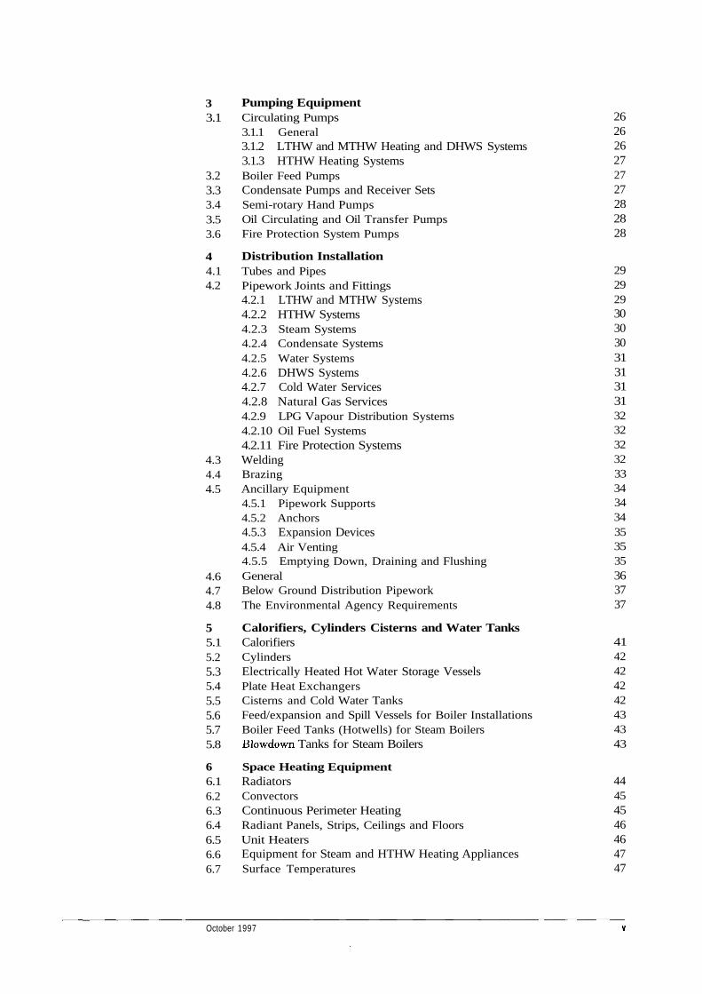
Pumping EquipmentCirculating Pumps3.1.1 General3.1.2 LTHW and MTHW Heating and DHWS Systems3.1.3 HTHW Heating SystemsBoiler Feed PumpsCondensate Pumps and Receiver SetsSemi-rotary Hand PumpsOil Circulating and Oil Transfer PumpsFire Protection System Pumps
Distribution InstallationTubes and PipesPipework Joints and Fittings4.2.1 LTHW and MTHW Systems4.2.2 HTHW Systems4.2.3 Steam Systems4.2.4 Condensate Systems4.2.5 Water Systems4.2.6 DHWS Systems4.2.7 Cold Water Services4.2.8 Natural Gas Services4.2.9 LPG Vapour Distribution Systems4.2.10 Oil Fuel Systems4.2.11 Fire Protection SystemsWeldingBrazingAncillary Equipment4.5.1 Pipework Supports4.5.2 Anchors4.5.3 Expansion Devices4.5.4 Air Venting4.5.5 Emptying Down, Draining and FlushingGeneralBelow Ground Distribution PipeworkThe Environmental Agency Requirements
Calorifiers, Cylinders Cisterns and Water TanksCalorifiersCylindersElectrically Heated Hot Water Storage VesselsPlate Heat ExchangersCisterns and Cold Water TanksFeed/expansion and Spill Vessels for Boiler InstallationsBoiler Feed Tanks (Hotwells) for Steam Boilers
Tanks for Steam Boilers
Space Heating EquipmentRadiatorsConvectorsContinuous Perimeter HeatingRadiant Panels, Strips, Ceilings and FloorsUnit HeatersEquipment for Steam and HTHW Heating AppliancesSurface Temperatures
262626272727282828
292929303030313131313232323233343434353535363737
4142424242434343
44454546464747
October 1997
77.17.27.37.47.57.67.77.87.97.107.117.127.137.147.157.167.17
88.18.2
8.3
8.4
99.1
9.29.39.49.59.69.7
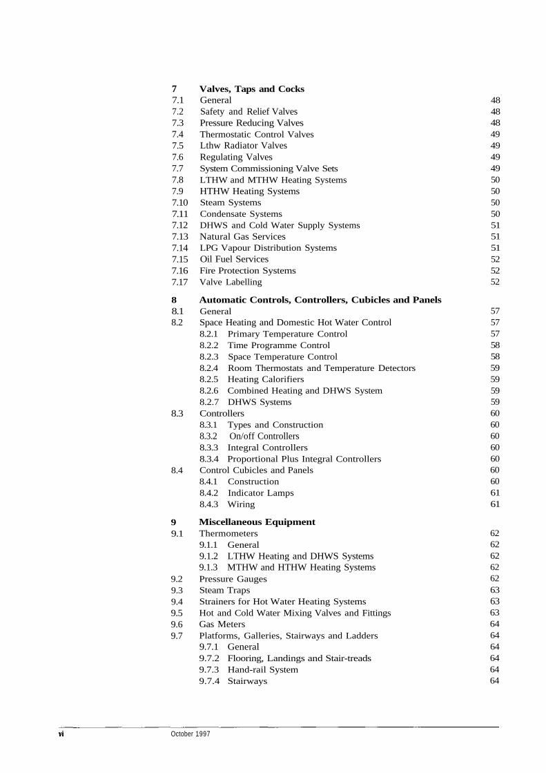
Valves, Taps and CocksGeneralSafety and Relief ValvesPressure Reducing ValvesThermostatic Control ValvesLthw Radiator ValvesRegulating ValvesSystem Commissioning Valve SetsLTHW and MTHW Heating SystemsHTHW Heating SystemsSteam SystemsCondensate SystemsDHWS and Cold Water Supply SystemsNatural Gas ServicesLPG Vapour Distribution SystemsOil Fuel ServicesFire Protection SystemsValve Labelling
Automatic Controls, Controllers, Cubicles and PanelsGeneralSpace Heating and Domestic Hot Water Control8.2.1 Primary Temperature Control8.2.2 Time Programme Control8.2.3 Space Temperature Control8.2.4 Room Thermostats and Temperature Detectors8.2.5 Heating Calorifiers8.2.6 Combined Heating and DHWS System8.2.7 DHWS SystemsControllers8.3.1 Types and Construction8.3.2 On/off Controllers8.3.3 Integral Controllers8.3.4 Proportional Plus Integral ControllersControl Cubicles and Panels8.4.1 Construction8.4.2 Indicator Lamps8.4.3 Wiring
Miscellaneous EquipmentThermometers9.1.1 General9.1.2 LTHW Heating and DHWS Systems9.1.3 MTHW and HTHW Heating SystemsPressure GaugesSteam TrapsStrainers for Hot Water Heating SystemsHot and Cold Water Mixing Valves and FittingsGas MetersPlatforms, Galleries, Stairways and Ladders9.7.1 General9.7.2 Flooring, Landings and Stair-treads9.7.3 Hand-rail System9.7.4 Stairways
4848484949494950505050515151525252
575757585859595959606060606060606161
6262626262636363646464646464
October 1997
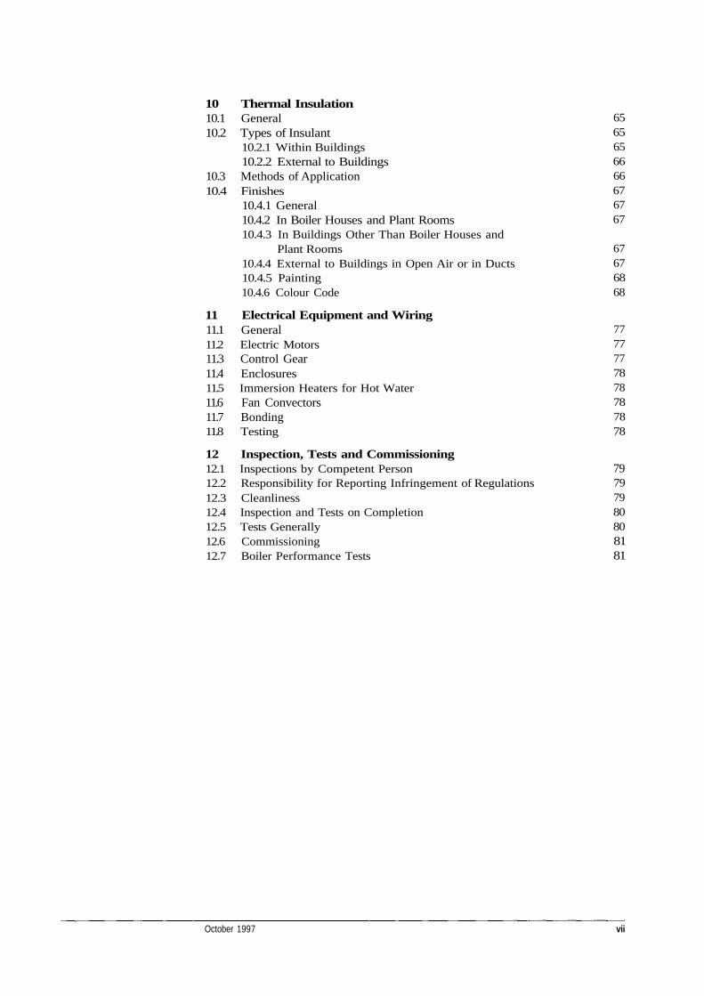
10 Thermal Insulation10.1 General10.2 Types of Insulant
10.2.1 Within Buildings10.2.2 External to Buildings
10.3 Methods of Application10.4 Finishes
10.4.1 General10.4.2 In Boiler Houses and Plant Rooms10.4.3 In Buildings Other Than Boiler Houses and
Plant Rooms10.4.4 External to Buildings in Open Air or in Ducts10.4.5 Painting10.4.6 Colour Code
11 Electrical Equipment and Wiring11.1 General11.2 Electric Motors11.3 Control Gear11.4 Enclosures11.5 Immersion Heaters for Hot Water11.6 Fan Convectors11.7 Bonding11.8 Testing
12 Inspection, Tests and Commissioning12.1 Inspections by Competent Person12.2 Responsibility for Reporting Infringement of Regulations12.3 Cleanliness12.4 Inspection and Tests on Completion12.5 Tests Generally12.6 Commissioning12.7 Boiler Performance Tests
October 1997 vii
6565656666676767
67676868
7777777878787878
79797980808181

Schedules
Schedule No. 1—Particular Application to this Contract . . . . . . 1 (of addendum)(12 Pages)
Schedule No. 2—Information to be Supplied by the Tenderer . . 1 (of addendum)(8 Pages)
viii October 1997
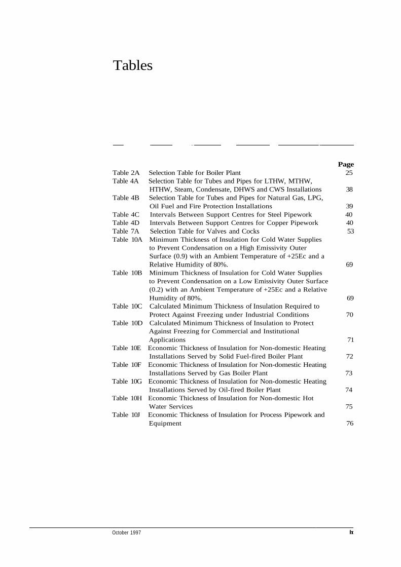
Tables
PageTable 2A Selection Table for Boiler Plant 25Table 4A Selection Table for Tubes and Pipes for LTHW, MTHW,
HTHW, Steam, Condensate, DHWS and CWS Installations 38Table 4B Selection Table for Tubes and Pipes for Natural Gas, LPG,
Oil Fuel and Fire Protection Installations 39Table 4C Intervals Between Support Centres for Steel Pipework 40Table 4D Intervals Between Support Centres for Copper Pipework 40Table 7A Selection Table for Valves and Cocks 53Table 10A Minimum Thickness of Insulation for Cold Water Supplies
to Prevent Condensation on a High Emissivity OuterSurface (0.9) with an Ambient Temperature of +25Ec and aRelative Humidity of 80%. 69
Table 10B Minimum Thickness of Insulation for Cold Water Suppliesto Prevent Condensation on a Low Emissivity Outer Surface(0.2) with an Ambient Temperature of +25Ec and a RelativeHumidity of 80%. 69
Table 10C Calculated Minimum Thickness of Insulation Required toProtect Against Freezing under Industrial Conditions 70
Table 10D Calculated Minimum Thickness of Insulation to ProtectAgainst Freezing for Commercial and InstitutionalApplications 71
Table 10E Economic Thickness of Insulation for Non-domestic HeatingInstallations Served by Solid Fuel-fired Boiler Plant 72
Table 10F Economic Thickness of Insulation for Non-domestic HeatingInstallations Served by Gas Boiler Plant 73
Table 10G Economic Thickness of Insulation for Non-domestic HeatingInstallations Served by Oil-fired Boiler Plant 74
Table 10H Economic Thickness of Insulation for Non-domestic HotWater Services 75
Table 10J Economic Thickness of Insulation for Process Pipework andEquipment 76
October 1997
Foreword
1. This Specification is one of a series prepared by the Defence EstateOrganisation primarily for use in its contracts for mechanical andelectrical engineering works. The Specification covers the installation ofheating, hot and cold water, steam and gas services for buildings otherthan dwellings. It is a revision of the former Standard Specification(M&E) No. 3, dated 1988, and Guidance Notes for Users, dated 1990.
2. When this Specification is used in connection with a Defence contractthen it is to be read in conjunction with such further documents settingout contractual requirements particular to the contract.
3. Whilst this Specification was commissioned by the DEO for use on MODcontracts, it is acknowledged that it could be usefully applied to othercontracts. DEO commends its use to other Government departments.
It may therefore be used outside the MOD estate. However, no warrantyis given as to the accuracy of this Specification or its fitness for anypurpose.
4. This Specification has been devised for the use of the Crown and itscontractors in the execution of contracts for the Crown. The Crownhereby excludes all liability (other than liability for death or personalinjury) whatsoever and howsoever arising (including, but withoutlimitation, negligence on the part of the Crown, its servants or agents) forany loss or damage however caused where the document is used for anyother purpose.
October 1997
Abbreviations
British CoalBritish Effluent and Water AssociationBritish Gas CorporationBritish StandardBritish Standard Euro NormBritish Standard Pipe threadChartered Institution of Building Services EngineersBritish Standard Code of PracticeCompetent PersonCold water supplyDomestic hot water serviceDefence Estate OrganisationElectric Resistance WeldedGross calorific valueGlass reinforced plasticsHigh temperature hot waterHeating and Ventilating Contractors AssociationInstitution of Electrical EngineersInstitution of Gas EngineersInternational Standards OrganisationLight emitting diodeLiquefied petroleum gasLow temperature hot waterMaximum continuous ratingMedium temperature hot waterNational Joint Industrial CouncilNoise ratingNational Rivers AuthorityProject ManagerParticular specificationSeamlessThermostatic radiator valve
October 1997
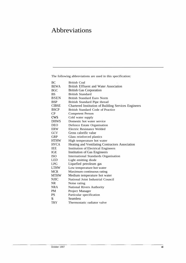
The following abbreviations are used in this specification:
BCBEWABGCBSBSENBSPCIBSEBSCPCPcwsDHWSDEOERWGCVGRPHTHWHVCAIEEIGEISOLEDLPGLTHWMCRMTHWNJICNRNRAPMPSsTRY
Amendments
Please use this table to make a note of any amendments issued.
October 1997
Heating, hot and cold water,steam and gas installations for buildings
Section One—General Requirements
SCOPE
1.1.1 This Specification details the design andother requirements for low, medium and hightemperature hot water heating installations, domestichot and cold water supplies, steam and condensate,gas and oil fuel services and fire protection systems,for buildings.
1.1.2 Unless otherwise indicated, the work shallinclude design, manufacture, works testing, supply,delivery to site, installation, site testing,commissioning, making good any defects that occurduring the defect liability period, provision of AsInstalled drawings and Operation and Maintenancedocuments, the whole of the labour, and all materialsnecessary to form a complete installation (whether ornot all the necessary components are indicated). Thework will also include any Scope of Work forming partof a Particular Specification attached to the Contract.
1.1.3 Where indicated, the work shall includecomprehensive planned preventive maintenance for aperiod of 12 months following acceptance of thecompleted installation.
1.2 DEFINITIONS
1.2.1 Where the work is to be undertaken as asub-contract, 'Contractor' shall mean 'Sub-contractor'.
1.2.2 'Indicated' as used in 'as indicated', 'whereindicated', 'unless otherwise indicated' and likephrases shall mean indicated in Schedule No. 1 of thisSpecification or in the other documents listed in theinvitation to tender.
1.2.3 'Approval' (and words derived therefrom)means approval in writing by the PM, unless statedotherwise.
1.2.4 Commissioning. The advancement of aninstallation from the stage of static completion to fullworking order to specified requirements.Commissioning includes the setting to work andregulation of an installation.
a) Setting to work. The process of setting astatic system into motion.
b) Regulation. The process of adjusting thesystem operating criteria to the specifiedrequirements.
1.2.5 Site Performance Testing. The evaluation ofthe performance of a commissioned installation.
1.2.6 Low temperature hot-water (LTHW) system.A system which operates at a maximum temperatureof 100°C and a minimum flow temperature of 70°C butwhich is not part of an MTHW or HTHW injectionsystem.
1.2.7 Medium temperature hot-water (MTHW)system. A pressurised system, either open or closed tothe atmosphere, which operates at temperatures above100°C and up to 120°C.
1.2.8 High temperature hot-water (HTHW)system. A pressurised system closed to the atmospherewhich operates at temperatures above 120°C.
1.2.9 Steam services. Steam heating and/ordistribution systems with working gauge pressure upto a maximum of 10 bar.
1.2.10 Gas, either manufactured gas (1st family),natural gas (2nd family), or LPG (3rd family) asindicated.
1.2.11 Pipework sizes.
a) DN shall refer to the nominal bore of steeltubes (mm). Copper tube sizes shall bereferred to by outside diameter in mm.
October 1997
Specification 036
Specification 036 Section One—General Requirements
b) Pipes, pipe fittings and valves designated'SIZE 1' etc., shall refer to items withthreaded BSP connections to BS 21.
c) Pipes, pipe fittings and valves designated'DN 50', 'DN 65' etc., shall refer to itemswhose bore sizes are nominally 50mm,65mm, etc.
1.3 RELATED DOCUMENTS
1.3.1 This Specification shall be read inconjunction with, and its requirements are in additionto, the general conditions of contract and anydrawings and other documents issued with it andlisted in the invitation to tender.
1.3.2 Any discrepancy between this Specification,the Conditions of Contract, other documents listed onthe tender form or the Contract Drawings shall bereferred to the relevant person designated in thetender documents as soon as practicable during pre-acceptance stage, or to the PM thereafter.
1.4 PROVEN PERFORMANCE
1.4.1 Systems and equipment selected by theContractor shall have performed successfully for notless than 2 years under the same conditions as thoserequired by the tender documents.
1.4.2 Systems and equipment that do not complywith the foregoing proven performance requirementmay be considered, provided full technical details andevidence of suitability are given at the time oftendering.
1.5 STANDARDS
1.5.1 Commodities specified to conform to BritishStandards shall be clearly and indelibly marked withthe reference specified. Where this is impracticable,the relevant advice and delivery notes shall includethe BS reference with which they are to comply.
1.5.2 Where commodities are specified asmanufactured by a BSI Kitemark Licensee or wherecommodities/services are specified to be RegisteredFirms (under BSI Assessment Schemes), themanufacturer/firm must be a current participant inthe relevant scheme.
1.5.3 Where commodities or systems are specifiedas certified by the British Board of Agrement, thecommodities or systems supplied shall be the subjectof a current BBA Certificate.
1.5.4 Where commodities/services are specified tobe by registered/approved firms (under ApprovedQuality Assurance Schemes), the manufacturer/firmmust be a current participant in the relevant scheme.
1.5.5 The equipment and/or installation(s) shallconform to the relevant British Standards and Codesof Practice current 3 months prior to the date forreturn of tenders, unless otherwise indicated.Certificates of compliance with British Standards, BSICertification Schemes, and/or Quality AssuranceSchemes, shall be provided to the PM at his request.
1.5.6 Materials and fittings for domestic hot waterand cold water systems shall be as listed in the WaterResearch Centre's 'Water Fittings and MaterialsDirectory' or, where not listed, shall comply with therequirements of the particular Water Company.
1.5.7 Gas fired equipment and appliances shallcomply with the requirements of the Gas Safety(Installation and Use) Regulations.
1.6 REGULATIONS
1.6.1 All work shall be carried out in accordancewith the MOD relevant Safety Regulations andProcedures which may be seen on request to the PM.
1.6.2 The installation(s) shall comply with and besubject to all relevant Statutory Instruments,Regulations, and special Guidance and Memorandawhich include the following:
a) The Health and Safety at Work, etc., Act.
b) Regulations under the Electricity Acts.
c) The Electricity at Work Act.
d) The Clean Air Act.
e) Control of Pollution Act.
f) Energy Conservation Act.
g) Regulations under the Factories Act.
h) The Building Regulations.
j) The Gas Safety (Installation and Use)Regulations.
k) The Control of Substances Hazardous toHealth Regulations (COSHH).
1) The Pressure Systems and TransportableGas Container Regulations.
m) The Construction (Design and Management)Regulations (CONDAM).
October 1997
Heating, hot and cold water,steam and gas installations for buildings
Specification 036 Section One—General Requirements
n) The Management of Health and Safety atWork Regulations (MHSW).
o) The Personal Protective Equipment at WorkRegulations (PPE).
p) BS 7671 : 1992 (Requirements for electricalinstallations. The IEE Wiring Regulations).
q) British Gas Corporation Codes of Practice.
r) The Institution of Gas Engineers utilizationprocedures (IGE/UP)
s) Any special requirements of the LocalElectricity, Gas or Water Companies andFire Fighting Authority.
t) The Asbestos Regulations.
u) The Boiler (Efficiency) Regulations.
v) HSE Guidance Note HS(G)70—The controlof legionellosis (including Legionnaires'disease).
w) CIBSE Technical Memoranda TM13:1991—Minimising the risk of Legionnaires'Disease.
1.6.3 The tender shall be based on theRegulations current 3 months prior to the date forreturn of tenders.
1.7 DRAWINGS
1.7.1 Working Drawings
1.7.1.1 Unless otherwise indicated, the Contractorshall provide working drawings for comment beforemanufacture or installation. The drawings shall show:
a) Fully dimensioned builder's workrequirements.
b) Details of plant rooms.
c) General arrangement of completeinstallation.
d) Details of any changes resulting fromInstructions given by the PM or agreementsreached with him.
e) Diagrams separately showing in detail allthe electrical circuit and wiring layouts and/or, where applicable, the pneumatic circuitrywithin the installation.
f) Layouts and details of control panels andcubicles.
g) Manufacturers' 'as made' drawings whererequired by the Specification.
1.7.1.2 With the agreement of the PM, holes,fixings, etc., other than in plant rooms, may bemarked out on site instead of on drawings.
1.7.1.3 An initial set of drawings described inClause 1.7.1.1 shall be sent to the PM for commentwithin five weeks of the acceptance of the tender.
1.7.2 ELECTRICAL, ELECTRONIC AND PNEUMATICDIAGRAMS
1.7.2.1 Electrical, electronic and pneumaticdiagrams shall comply with the following:
a) Composite circuit and layout diagrams forelectrical, electronic and pneumatic servicesshall detail all circuitry within main controlpanels and also connection diagrams for allexternal equipment eg. starters,thermostatic and pneumatic controls devices,all automatic firing and mechanical draughtequipment, together with all inter-connecting wiring or pipework from themain point of supply onwards, and allterminal markings.
b) The sizes and types of all cables and pipesshall be indicated on the layout diagrams,together with the ratings of all items such asfuses, switches, valves, controllers, etc.
c) Circuit diagrams shall, where possible, be soarranged that the main sequence of eventsis from left to right and from top to bottomof the diagram. Diagrams shall generallycomply with BS 3939—Graphical symbolsfor electrical power, telecommunications andelectronic diagrams.
d) Where abbreviations are employed for thedesignation of components a schedule shallbe provided on the drawings to explain theirmeanings.
e) A print of each of the composite circuit andlayout diagrams shall be fixed securely tothe inside of the hinged front of the mainelectrical and pneumatic control panels, asappropriate, or in such other positions asmay be agreed with the PM and shall be
October 1997
Heating, hot and cold water,steam and gas installations for buildings
Specification 036 Section One—General Requirements
f)
protected by non-flammable transparentmaterial. Where inadequate space exists theprints shall be suitably reduced in size.
Individual circuit and layout drawings fromcomponent manufacturers will not beaccepted in lieu of composite diagrams.
1.7.3 'As Installed'Drawings
1.7.3.1 Unless otherwise indicated, the Contractorshall provide four sets of approved drawings whichshall show the following, where applicable:
a) The complete installation including the sizesand routes of all pipework.
b) The precise location of all pipework which isburied within the structure and thosesections of any external distributionpipework which are buried in the ground.
c) The precise positions of all undergroundcold-water and gas service points at theentry to buildings, giving their depth andthe locations of the service isolating valvesor cocks.
d) Any special thermal or other protectingenvelopes around services which are buried.
e) The geographical location and identificationnumber of each circuit control valve inaccordance with the labelling and circuitcontrol diagram required by Clauses 7.17.1and 7.17.2.
f) The names of the manufacturers, model andtype numbers and all details of duty andrating of all items of plant includingautomatic controls equipment.
1.7.3.2 Unless otherwise indicated, draft copies ofthese drawings shall be submitted to the PM, forapproval, prior to completion of the Works. Finalapproved drawings shall be supplied to the PM notlater than one month before the date for completion ofthe Works (or such other time as may be agreed withthe PM). Failure to do so could cause delay in anyrelease which it is considered may be made from theReserve on the completion of the Works or during themaintenance period, and in the settlement of the finalaccount.
1.7.3.3 Each drawing shall be in accordance withBS 308: Part 1 (to ensure suitability for micro-filming), and shall be a process negative on
translucent material, not paper, of a standard size Alto A4. Where agreed by the PM microfiche copies orCAD disks in agreed format may be supplied.
1.7.3.4 The words 'AS INSTALLED' shall beinserted in 19mm block letters adjacent to the titleblock of each drawing, together with the name of thesite, the building, the title of the installation, thecontract number and the name of the Contractor.Each drawing shall be dated.
1.7.3.5 During the course of the Works, theContractor shall maintain a fully detailed record of allchanges from the initial Contract Drawings tofacilitate easy and accurate preparation of the 'AsInstalled' drawings and to ensure that these drawingsare in all respects a true record of the installation.
1.8 OPERATING AND MAINTENANCEDOCUMENTS
1.8.1 Unless otherwise indicated, the Contractorshall provide two separate copies of approved Healthand Safety File, including: operating and maintenancedocuments, and a completed set of the plannedmaintenance data sheets for the whole of theinstallation covered by the Contract. Thesedocuments shall contain all relevant information forthe safe operation and maintenance of the system.Where applicable, the supply of information shallaccord with the relevant requirements of the PressureSystems and Transportable Gas ContainersRegulations.
1.8.2 Unless otherwise indicated, a draft copy ofthe document shall be submitted to the PM, forapproval, prior to completion of the Works. Finalapproved documents shall be supplied to the PM notlater than one month before the date for completion ofthe Works (or such other time as may be agreed withthe PM). Failure to do so could cause delay in anyrelease which it is considered may be made from thereserve on completion of the Works or during themaintenance period, and in the settlement of the finalaccount.
1.8.3 Documents are to be bound in strong flexibleand durable covers with four hole binding to acceptstandard punched A4 sheets to BS 5097: Part 1.Documents shall be indexed for ease of reference.
1.8.4 Operating and maintenance instructionsmay be designed to be read in conjunction with 'AsInstalled' drawings and shall include the following:
October 1997
Heating, hot and cold water,steam and gas installations for buildings
Specification 036 Section One—General Requirements
a) A general description of the scope, purposeand manner of working of each system orapparatus forming part of the Works.
b) Data on general setting of controlsassociated with controlling designconditions, monitoring instruments andswitchgear.
c) Instructions for safe starting up, operatingand shutting down of each system.
d) Instructions for dealing with fault diagnosisand remedial action of each system.
e) Any precautionary measures necessary forensuring health and safety and avoidance ofmisuse.
f) Instructions for planned preventivemaintenance to maintain the equipment inaccordance with the manufacturers'recommendations.
g) The names and addresses of suppliers of allmajor components.
h) Spare parts lists for consumablecomponents.
1.9 ELECTRICITY SUPPLY
1.9.1 Unless otherwise indicated all apparatusand wiring shall be suitable for use with a 3-phase, 4wire, 400/230 volt 50 Hz earthed neutral system.
1 . 1 0 ELECTRICAL EQUIPMENT AND WIRING
1.10.1 Bonding of all extraneous conductive partsof the installation (including metallic pipework,insulation cladding etc.) shall be carried out inaccordance with BS 7671 Requirements for electricalinstallations (The IEE Wiring Regulations).
1 . 1 1 PAINTING
1.11.1 Ferrous sheet metal work not galvanisedshall have protective coats of primer paint andundercoat or other approved material before despatchfrom works. Other ferrous materials shall receive aprotective coat at works where it is normal custom.Any deterioration or damage to manufacturers'protective coatings during storage, installation, andbefore Handover shall be made good by the Contractorto the satisfaction of the PM.
1.11.2 Unless otherwise indicated the Contractorshall be responsible for painting:
a) Condensate receivers, cisterns, tanks andhot wells (Clauses 3.3.7, 5.5.4, 5.6.1 and5.7.1).
b) Oil storage tanks as required by BS 799:Part 5 and this specification.
c) Thermal insulation (Clauses 10.4.5.1 and10.4.5.2).
d) Areas of deterioration or damage tomanufacturer's protective coating asdescribed in Clause 1.11.1.
1.11.3 The external surfaces of all ferrous metalwork including pipework, hangers, supports etc.,which are not to be insulated, and are not galvanisedor otherwise protected against corrosion, shall beprimed and finished with a paint system to BS 5493as indicated. The surface of all ungalvanised ferrouspipework which is to be insulated, shall be finishedwith two coats of aluminium paint. The Contractorshall ensure that:
a) Surfaces are cleaned in accordance with allrelevant parts of BS 7079 before they arepainted.
b) Those parts of the installation required to beleft unpainted (eg. brasswork) shall be soleft.
c) The pipework services are correctlyidentified to ensure the use of approvedpaint of the correct colour to comply with BS1710 and the PM's instructions.
1.11.4 When the Works covered by thisSpecification are carried out as a sub-contract theSub-Contractor will apply the priming and finishingcoats, unless otherwise stated.
1 . 1 2 ASBESTOS MATERIALS
1.12.1 Asbestos materials shall not be installed.This requirement applies to major items eg. thermalinsulation and to sundry minor components such asgaskets, fire seals and valve packings.
1 . 1 3 CFCS AND HCFCS
1.13.1 Products containing and/or requiring the useof CFCs and HCFCs in their manufacture, will not bepermitted.
October 1997
Heating, hot and cold water,steam and gas installations for buildings

Section One—General Requirements
1.14.1 Schedule No. 1 to this StandardSpecification gives information to tenderers relating tothe clauses where options or specific numbers etc.require stating.
October 1997
Heating, hot and cold water,steam and gas installations for buildings
Specification 036
1.14.2 Schedule No. 2 to this StandardSpecification is for tenderers to complete and returnas part of their tenders.
1.14 SCHEDULES
Specification 036 Heating, hot and cold water,steam and gas installations for buildings
Section Two—Central Plant
2.1 BOILERS—GENERAL
2.1.1 These General Requirements shall apply inpart or in whole to boilers described in this Section.
2.1.2 Boilers and associated firing equipmentshall be of approved design and shall conform to therequirements as indicated.
2.1.3 All necessary fittings and equipment forautomatic control shall be supplied with each boiler.
2.1.4 Each solid fuel boiler installation shall haveone set of operating tools comprising heavy patternsteel shovel, scraper, slice bar, clinker tongs, wire fluebrush and de-ashing rake, where applicable. Oil-firedand gas-fired boiler installations shall have a set offlue and tube cleaning tools appropriate to the boilers.The tools shall be hung on a rack supplied and fixedby the Contractor in a position indicated by the PM.
2.1.5 Where brick or concrete bases are to beprovided by a Building Contractor, the Contractorshall provide all dimensions and details to enable thebases to be designed and set out. For boilers withoutwater-cooled bottoms forming an integral part of thecirculation, and for other boilers where indicated, aninsulated and ventilated base will be provided by theBuilding Contractor to their design and for which theContractor shall furnish all necessary information ondimensions and weights.
2.1.6 The thermal efficiencies of the boilers atmaximum and minimum firing rates and at aboutmidway between, as relevant, shall be not less thanthose indicated when the boilers are tested atcompletion. See Section 12.
2.1.7 Valving to boilers flow and returnconnections shall be to clauses 30.1 and 30.2 of BS759: Part 1. Where additional valves are installed andare separated by a length of pipe, this length shallhave a drain cock and air vent.
2.1.8 The heat release rate to each furnace tubebased on fuel input (Gross Calorific Value—GCV) ORthe nominal output at 80% efficiency shall not exceed1800W/m3. (Not steam boilers).
2.1.9 The hot face metal temperature of the firstpass reversal chamber tube plate calculated to BS2790 Appendix C shall not exceed 380°C.
2.1.10 The boiler shall operate satisfactorily usingwater with Total Dissolved Solids (TDS) up to 3500ppm. (Not steam boilers).
2.1.11 Boiler exit gas temperatures generally shallnot exceed 260°C. Boiler exit gas temperatures on oil-fired installations shall not fall below 180°C unlessotherwise indicated.
2.1.12 The gas-side resistance between the fuelfiring equipment and boiler exit shall not exceed15 mbar.
2.1.13 For steam boilers the water surface area inthe steam shell shall be sufficient to ensure that thesteam disengagement velocity does not exceed 0.06 m/sat working pressure.
2.1.14 Steam at entry to the pressure main shallhave a minimum Dryness Fraction (DF) of 0.98.
2.2 STEAM BOILERS
2.2.1 Water Tube Boilers
2.2.1.1 In addition to the requirements in Boilers-General and those of BS 1113 the following shallapply:
a) The furnace shall be of membrane water-wall construction with a minimum ofrefractory material.
b) The heat release rate to the furnace fromthe stoker/burner shall be no greater than362kW/m3.
October 1997
Specification 036 Section Two—Central Plant
c) The boiler shall operate satisfactorily usingwater with total dissolved solids (TDS) up to3000ppm.
d) A furnace observation port with sight glassof minimum diameter 50mm and protectiveshutter shall be provided.
2.2.2 Steel Shell, 3-Pass Economic Boilers
2.2.2.1 In addition to the requirements of BS 855 orBS 2790 as indicated, the following shall apply:
a) An observation port with sight glass ofminimum diameter 50mm and protectiveshutter shall be provided for each furnacetube. The port shall be positioned at therear of the gas reversal chamber to view theflame within the furnace tube. The sightglass and protective shutter shall be readilyremovable to permit the use of water-cooledsuction pyrometers.
b) The attachment of tubes to the first-passreversal chamber tube plate in shell boilersbuilt to either BS 2790 or BS 855 shall be asfollows:
Boilers built to BS 2790:Stay tubes: Figure 3.9.2 (l)(d)Plain tubes: Figure 3.9.2(l)(d) or Figure3.9.2(2)(b)
Boilers built to BS 855:Stay tubes: Figure 26(d)Plain tubes: Figure 26(b) or Figure 26(d)
2.2.3 Steel Shell Reverse-Flame Boilers
2.2.3.1 In addition to the general requirements ofBS 855 or BS 2790 as indicated, the following shallapply:
An observation port with sight glass of minimumdiameter 50mm and protective shutter shall beprovided for the furnace tube. The port shall bepositioned to provide a view of the flame within thefurnace tube. The sight glass and protective shuttershall be readily removable to enable the use of water-cooled suction pyrometers.
2.2.4 Continuous-Coil Steam Generators
2.2.4.1 In addition to the requirements of BS 1113the following shall apply:
a) The overall boiler heat transfer rate basedon the fuel input (gross calorific value) and80% efficiency shall not exceed 70kW/m2 ofheating surface.
b) A dynamic steam separator shall be fittedand the steam at entry to the pressure mainor common steam manifold shall have aminimum dryness fraction of 0.98.
c) Positive blow-down arrangements shall beprovided for the water circuit and the boilershall be capable of satisfactory operationusing water having total dissolved solids(TDS) up to 3000ppm.
d) A furnace observation port complete withsight glass of minimum diameter 50mm andprotective shutter shall be provided.
2.2.5 Electrode Boilers
2.2.5.1 In addition to the requirements of BS 1894the following shall apply:
a) The boiler shell shall be of welded steelconstruction.
b) The steam at entry to the pressure main orcommon steam manifold shall have aminimum dryness fraction of 0.98.
c) The boiler shall be capable of delivering itsrated output when operated with water ofspecific resistance not less than 500 ohm cmat 65°C, under normal operating pressureand with a feed water temperature of 15°C.
2.2.6 Waste Heat Boilers
2.2.6.1 In addition to the requirements of BS 855,BS 1113 or BS 2790 as indicated, the following shallapply:
a) The boiler shall be matched to therequirements of the installations producingthe waste gas.
b) The boiler shall be capable of satisfactoryoperation using water having total dissolvedsolids (TDS) up to 3500ppm.
c) Boilers shall be capable of withstanding thepassage of the hot waste gas when drainedof water as indicated.
October 1997
Heating, hot and cold water,steam and gas installations for buildings
Specification 036 Section Two—Central Plant
2.2.7 Electrical Resistance Heated Boilers
2.2.7.1 In addition to the requirements of BS 1894or BS 5500, as indicated, the following shall apply:
a) The boiler shell shall be of welded steelconstruction.
b) The elements shall be of the heavy-dutycopper or stainless steel sheathed wire typeand shall be removable.
c) The boiler shall be thermally insulated andprovided with a protective sheet metalcabinet.
2.3 HOT WATER BOILERS
2.3.1 Water Tube Boilers
2.3.1.1 In addition to the requirements of BS 1113,Boilers—General and Water Tube (Steam) boilers, thefollowing shall apply:
a) Arrangements shall be made for positivewater mixing to be induced within the boiler.
b) Water flow resistance(s) between boiler(s)flow and return connections shall not exceedthe value(s) indicated.
2.3.2 Steel Shell 3-Pass Economic Boilers
2.3.2.1 In addition to the requirements of BS 855 orBS 2790 as indicated the following shall apply:
a) The design shall incorporate furnaceobservation port and tube attachmentarrangements as for steam boilers (2.2.2.1).
b) Arrangement shall be made for positivewater mixing to be induced within the boiler.
c) Water flow resistance(s) between boiler(s)flow and return connections shall not exceedthe value(s) indicated.
2.3.3 Steel Shell Reverse-Flame Boilers
2.3.3.1 In addition to the requirements of BS 855 orBS 2790 as indicated the following shall apply:
a) The design shall incorporate furnaceobservation port and tube attachmentarrangements as for steam boilers.
b) Arrangement shall be made for positivewater mixing to be induced within the boiler.
c) Water flow resistance(s) between boiler(s)flow and return connections shall not exceedthe value(s) indicated.
2.3.4 Continuous-Coil Hot Water Boilers
2.3.4.1 In addition to the requirements of BS 1113as indicated the following shall apply:
a) The overall boiler heat transfer rate basedon the fuel input (GCV) and 80% efficiencyshall not exceed 70kW/m2 of heating surface.
b) Water flow resistance(s) between boiler(s)flow and return connections shall not exceedthe values indicated.
2.3.5 Electrode Boilers
2.3.5.1 In addition to the requirements of BS 1894,the following shall apply:
a) The boiler shell shall be of welded steelconstruction.
b) The boiler shall be capable of delivering itsrated output when operated with water ofspecific resistance not less than 500 ohm cmat 65°C, under normal operating pressureand with an average water temperaturedifference (between inlet and outlet) of65K + 5K.
c) Water flow resistance(s) between boiler(s)flow and return connections shall not exceedthe value(s) indicated.
2.3.6 Waste Heat Boilers
2.3.6.1 In addition to the requirements of BS 855,BS 1113 or BS 2790, as indicated, the following shallapply:
a) The boiler shall be matched to therequirements of the installations producingthe waste gas.
b) Arrangements shall be made for positivewater mixing to be induced within the boiler.
c) Water flow resistance(s) between boiler(s)flow and return connections shall not exceedthe value(s) indicated.
d) The boiler shall be capable of withstandingthe passage of the hot waste gas whendrained of water as indicated.
October 1997
Heating, hot and cold water,steam and gas installations for buildings
Heating, hot and cold water,steam and gas installations for buildings
Section Two—Central Plant
2.3.7 Cast-iron Sectional Boilers
2.3.7.1 In addition to the requirements of BS 779the following shall apply:
a) Boilers may be supplied factory assembled orin sections complete with manufacturer'sinstructions and all materials required forsite assembly. The Contractor shall complywith the manufacturer's handling, erectionand installation instructions.
b) Boilers shall be installed on purpose-madestands or plates which ensure thatirregularities in the base do not interferewith the correct mating of the sections.
c) Facilities shall be provided for cleaningflueways. Access doors shall be designed forsimple removal and replacement and shallclose with a gas-tight seal. Hinged doors shallbe provided with stops where necessary toprevent damage to the insulation and casing.
d) Arrangements shall be made for positivewater mixing to be induced within the boiler.
e) A protective casing and insulating jacketshall be provided.
2.3.8 Steel 'Box-Type' Boilers
2.3.8.1 In addition to the requirements of BS 855the following shall apply:
a) Boilers shall be of welded steel construction.
b) Facilities shall be provided for cleaningflueways. Access doors shall be designed forsimple removal and replacement and shallclose with a gas-tight seal. Hinged doors shallbe provided with stops where necessary toprevent damage to the insulation and casing.
c) Arrangements shall be made for positivewater mixing to be induced within the boiler.
d) A protective casing and insulating jacketshall be provided.
2.3.9 Modular Boilers of Low Water Content
2.3.9.1 In addition to the requirements of therelevant BS, the following shall apply:
a) The modules shall be identical and shallconsist of cast iron sections or finned coppertubes expanded into cast iron or mild steelheaders.
b) The modules shall be connected in parallelso that water from the common returnheader flows through the modules to thecommon flow header.
c) Boilers shall be designed to be fired bynatural gas or LPG.
d) Boiler casings shall be insulated andprovided with condensate drains.
e) The boiler flow header shall have provisionfor connecting a safety valve, pressuregauge, open vent, thermometer and a flowsensor as indicated.
2.4 DOMESTIC HOT WATER HEATERS
2.4.1 Electrical Resistance Heaters
2.4.1.1 In addition to the requirements of therelevant BS, the following shall apply:
a) The heater shell shall be of welded steelconstruction to BS 5500.
b) The heating elements shall be of the heavyduty copper sheathed wire type and shall bewithdrawable.
c) The heater shall be insulated and providedwith a protective sheet metal cabinet.
2.4.2 Oil or Gas-Fired Water Heaters
2.4.2.1 In addition to the requirements of therelevant BS, the following shall apply:
a)
b)
c)
d)
e)
The heater shall be of all-welded steelconstruction or may be constructed ofwelded modules bolted together.
The shell interior and heat exchangesurfaces shall be coated with a scale andcorrosion resisting substance or shall bemanufactured of a corrosion resistingmaterial.
The burners shall be matched to theindividual flues and shall be fired by ClassD oil to BS 2869: Part 2, natural gas orLPG.
The heat exchangers shall flex when heatedor have other approved positive provision tocontrol scale formation.
A protective casing and insulating jacketshall be provided.
10 October 1997
Specification 036
Specification 036 Section Two—Central Plant
2.5 CONDENSING BOILERS
2.5.1 Unless otherwise indicated condensingboilers shall be as fully modulating gas-fired boilerswith an additional heat exchanger fitted in the fluegas outlet from the main heat transfer section, andarranged so that the boiler return temperature shallbe low enough to promote flue gas condensation.
2.5.2 The condensing section heat exchanger shallbe of material indicated. Where it is necessary to usecorrosion these shall be as recommended bythe boiler manufacturer.
2.5.3 Flue gas discharge shall be fan-assisted.Flues and chimneys shall be resistant to corrosion andbe compatible with the boiler manufacturer'srequirements. Spigot joints shall be upwardfacing andbe sealed.
2.5.4 Flue branches shall be graded 3% minimum.Connections between boilers and chimneys shall beinstalled to a continuous rise.
2.5.5 The condensing section shall have a trappedcondensate outlet. Connections from this outlet andfrom a trapped outlet at the chimney base shall beextended in polypropylene piping to the nearestsuitable drain at a gradient of 3% minimum.
2.6 BOILERS EQUIPMENT
2.6.1 General
2.6.1.1 The Contractor shall be responsible forensuring that the boiler manufacturer has approvedthe firing equipment offered to match the boilers theyare intended to fire, in order to ensure completelysatisfactory service. Evidence of proved compatibilityshall be given, when requested by the PM.
2.6.1.2 Boilers shall be purpose-designed for firingby one of the following methods as indicated:
a) oil fuel with automatic burner;
b) solid fuel with mechanical, fixed grate ormagazine type stoker;
c) gas with automatic burner, either forced airor atmospheric;
d) dual or multi-fuel firing (solid fuel/oil/gas).
2.6.1.3 All plant and equipment shall be selected tooperate with noise levels that do not exceed thoseindicated.
2.6.2 Steam Boilers
2.6.2.1 Equipment of steam boilers shall complywith BS 759 and shall include the following for eachboiler. The position of these shall be in accordancewith manufacturer's standard arrangements.
a) Two safety valves, to BS 6759, mountedeither singly or as a pair on a common body.
b) Lockable stop valve(s) as close as possible tothe boiler (see Clause 2.1.7).
c) Steam pressure gauge.
d) Two independent water level gauges directlyconnected to the boiler shell (except boilersof less than 145kg/hour capacity for whichone water level gauge is acceptable).
e) External feed water control, high and lowwater level control and alarms, and anindependent overriding low water levelcontrol with its alarm; each fitted withsequencing blow-down valves and lockablesteam isolating valves. With the PM's priorapproval, direct mounted internal controlsincorporating a testing device may be fittedon boilers up to 2250kg/h capacity if this isthe boiler manufacturer's standardarrangement.
f) Lockable feed stop-and-check valve.
g) Manual blow-down valve (handle onlyremovable when valve is closed) with asingle handle for a range of boilers, orautomatic blow-down valve or continuousblow-down valve with heat recovery, (as for'Steam Boiler Blowdown').
h) Means for attaching a test pressure gauge.
j) Marked on the boiler, or on a plate attachedto it, in a visible, legible and indelible form:
the manufacturer's name;
a serial number to identify the boiler;
the date of manufacture of the boiler;
the standard to which the boiler was built;
the maximum design pressure of theboiler;
the minimum design pressure of the boilerif it is other than atmospheric;
the design temperature.
October 1997 11
Heating, hot and cold water,steam and gas installations for buildings

Specification 036 Section Two—Central Plant
k) A plate bearing a distinct and easily visiblelocal number as agreed with the PM wheretwo or more boilers are provided.
2.6.3 Hot Water Boilers
2.6.3.1 Equipment of boilers for water systems shallcomply with BS 759, BS 855 and BS 779, asapplicable, and shall include the following for eachboiler. The positions of these shall be in accordancewith manufacturer's standard arrangements.
a) One or two safety and gate/parallel-slidevalves as required by the relevant BS.
b) Open vent pipe on LTHW systems whenthese are open to atmosphere.
c) Pressure gauge.
d) Thermometer.
e) Emptying cock(s) or drain valve(s) to beoperated by removable key.
f) Marked on the boiler, or on a plate attachedto it, in a visible, legible and indelible form:
the manufacturer's name;
a serial number to identify the boiler;
the date of manufacture of the boiler;
the standard to which the boiler was built;
the maximum design pressure of theboiler;
the minimum design pressure of the boilerif it is other than atmospheric;
the design temperature.
g) A plate bearing a distinct and easily visiblelocal number as agreed with the PM wheretwo or more boilers are provided.
2.6.3.2 On installations of two or more LTHWboilers, open to atmosphere, the open vent pipe fromeach boiler may be connected into a common vent pipethrough a three-way cock so arranged that in nocircumstances can any boiler be isolatedsimultaneously from the open vent pipe and from thefree outlet.
2.7 INSTALLATIONS
2.7.1 Solid Fuel Installations
2.7.1.1 Solid fuel and ash handling and soot blowersystems shall be provided as indicated.
2.7.2 Oil Fired Installations
General
2.7.2.1 Oil-fired installations shall comply with BS799 Parts 3, 4 and 5 and BS 5410 Part 2 unlessotherwise indicated.
2.7.2.2 Plant shall be designed and installed tooperate in such a way that no smell of oil penetratesbuildings or parts of buildings within the vicinity ofthe boiler house and oil store.
2.7.2.3 Oil-burning installations in excess of 6MW(9600kg/hour) capacity and utilising Class F oil to BS2869: Part 2 shall also be able to burn Class G oil.
Oil Storage Tanks
2.7.2.4 Oil storage tanks, including fittings shall beconstructed to BS 799 Part 5 and shall be of the typeand size as indicated.
2.7.2.5 Oil storage tanks shall be inspected, testedand certified by the relevant Competent Person(Section 12).
2.7.2.6 Unless otherwise indicated the exteriors ofexposed, above-ground oil tanks shall be paintedincluding thorough cleaning of the steel in accordancewith the recommendations of all relevant parts of BS7079, rust inhibitor, primer and 2 coats of oil resistantfinish paint and buried tanks shall have 3mm bitumencoating in lieu of the finish paint. The interior of alltanks shall be wire brushed but not painted except forzinc phosphate alkyd corrosion protection of theunderside of the crown of large vertical cylindricaltanks. External insulation shall be as indicated.
Tanks shall be located in an oil-tight bund withimpervious sump, impervious base, no damp courseand no drainage outlet, and sized to accept 110% ofthe volume of the tank.
2.7.2.7 Buried tanks shall be suitably anchored.Prior to installation external surfaces shall bethoroughly cleaned of rust, scale, grease and oil andpainted a 3mm coat of filled bitumen. The installationof the tank shall be to clause 45.2.3 of BS 5410 Part 2.
12 October 1997
Heating, hot and cold water,steam and gas installations for buildings
Specification 036 Section Two—Central Plant
Oil Tank Fittings and Feed Line
2.7.2.8 Tank installations shall be fitted or providedwith the following:
a) A non-corrodible plate approximately250 x 100mm at each filling point clearlyand indelibly inscribed 'Boiler Fuel' andbearing the BS 2869: Part 2 class of oil to besupplied to the system, together with apermanent identifying plate to clause 5.5 ofBS 799 : Part 5.
b) A dip stick or tape with calibrated chart foreach tank, as indicated. The units employedshall be litres for tanks up to 1000 litres,and m3 above 1000 litres.
c) A contents gauge of the continuousindication type with remote reading. Thegauge shall be of a weatherproof pattern orlocated in a weatherproof housing. Thegauge shall be operated by hydrostatically,electrically, by magnetic float or otherapproved means. The capillary transmitterof hydrostatic gauges shall be replaceable.The gauge shall be marked 'FULL' and'EMPTY' to indicate the limits of usable oilin the tank ie. to correspond with high-levelalarm and fuel outlet levels respectively.Gauges on tanks shall be calibrated in litresfor tanks up to 1000 litres capacity and inm3 for capacities above.(Note: Battery-powered devices are notpermitted).
d) A weatherproof audible warning bell or otherapproved device, arranged for muting andautomatic reset to give clear warning at thefilling point when the tank has been filled to90% capacity. A plate similar to that for fuelidentification shall be fitted near thewarning device to indicate its purpose.(Note: Battery-operated devices are notpermitted).
e) An outflow heater supplemented by a de-sludging coil for both Class F and G oils.
f) An oil flow temperature indicator for bothClass F and G oils.
g) A tank immersion heater for Class D oil,where indicated.
2.7.2.9 The oil feed line(s) shall be provided withthe following:
a) First stage filters of the dual type withisolating valves and drain cock.
b) A bulk oil flow meter where the total ratedoil consumption exceeds 25 litre/hour.
c) A valved by-pass for insertion of a testmeter, adjacent to each burner where theboiler rating exceeds 150kW (240 kg/h steamoutput).
d) A self regulating or thermostaticallycontrolled moistureproof type of electrictrace heating on the oil feed lines for ClassesF and G oil and for Class D oil whereindicated. The tracer shall be rated to givenot less than 40 watt per metre length offeed line and shall keep the oil(s) at or abovethe indicated temperatures. The tracer andpipe together shall be thermally insulatedand weatherproofed in accordance withSection 10.
e) Oil circulating pumps in accordance withSection 3 where indicated.
f) A fire valve with fusible link or othertemperature operated quick release devicearranged as for the fire valve systemspecified in Clause 2.7.2.3.3.
g) A shut-off valve, electrically or mechanicallyoperated by a float mechanism contained ina mild steel open top tank of not more than25 litres capacity. The tank shall becontained within a sump as small as ispracticable to house it, located at the lowestpoint in the floor of the boiler house butseparated from any pit connected to themain drainage system. Floor ducts, etc, asnecessary shall be provided to ensure thatany oil leakage readily drains into the floortank. When electrically operated, the valveshall shut on the breaking of the circuit.Unless a fault condition exists, it shall openautomatically, without manual resetting,upon the restoration of electrical supplyfollowing an interruption. The shut-offvalve may be additional to the fire valve (asabove) or, where the fire valve wouldotherwise be of the electrically maintainedtype and the sump float is connectedelectrically to a shut-off valve, the thermalfuses for the fire valve and the sump floatswitch may be wired in series to a singleelectrically maintained valve.
October 1997 13
Heating, hot and cold water,steam and gas installations for buildings
Specification 036 Section Two—Central Plant
2.7.2.10 The fire valve system shall be arranged asfollows:
a) Each fusible link or other temperatureoperated quick release device controlling thefire valve in the oil-feed line shallincorporate a switch arranged to break thecontrol circuits and shut down the oilhandling and burning plant only when thefusible element is broken, or the quick-release device is operated (ie the systemwater circulating pumps, etc, must remainin operation). Electrical terminals suitablefor 230 volts 50 Hz shall be incorporated inthe switch from which connections can betaken, under separate contract.
b) Each fire valve system shall be providedwith a manual quick-release device ormanually reset pushbutton to close the firevalve in an emergency and for testingpurposes. The device or switch shall bepositioned close to the main boiler room exitand identified by a white plastic plate notless than 100mm long x 75mm high, withan inscription engraved in 10mm redlettering to suit the action required, such as:FIRE. IN CASE OF FIRE STRIKE KNOB.
2.7.2.11 Wires for mechanically operated fire valverelease systems shall be of stainless steel. Pulleysshall be free-running with a minimum diameter of50mm and shall retain the wires without binding.
2.7.2.12 Valves and cocks of any tank not within abuilding shall be lockable.
Oil Heating
2.7.2.13 Tank and system heaters shall be electric,water/electric or steam/electric, as indicated, and shallbe thermostatically controlled.
2.7.2.14 Condensate from steam heated coils is to befree draining and shall discharge via a steam trap towaste.
2.7.2.15 Hot water supplies for heating coils shall beprovided from the secondary circuit of a non-storagecalorifier.
2.7.2.16 Design temperatures and construction shallbe in accordance with BS 799 Part 5 and BS 5410Part 2.
2.7.2.17 Each outflow heater shall be bolted to aflanged stool in the tank and shall incorporate:
a) An outflow temperature indicator.
b) A weatherproof terminal box enclosing allelectrical connections.
2.7.2.18 De-sludging coils shall extend one third ofthe distance across the tank. They shall be mountedto enter and exit from the tank beneath the level ofthe outflow and adjacent to the drain valve; and shallbe sized to permit free flow of otherwise cold oil acrossthe tank to the outflow. Control shall be by handoperated shut-off valve.
Oil Burners
2.7.2.19 Oil burners shall be of the fully automatictype incorporating oil pressure gauges and, ifrequired, oil pre-heaters and temperature indicators.Ignition shall be electric or gas/electric, employingnatural gas or LPG. Gas systems shall include allnecessary pipework, valves and controls for safeconnection to natural gas mains, LPG mains, or toLPG bottles supplied by contractors under otherarrangements.
2.7.2.20 Burners, oil pipes and cables shall beinstalled so as to provide ample facilities for inspectionand maintenance. All adjustments shall be providedwith pre-setting arrangements so that they are notaltered by normal cleaning and day-to-daymaintenance.
2.7.2.21 Except where small burners are mounteddirectly on the boiler front, and means of easy accessto the combustion head components is provided,burner units shall be mounted in such a way that thewhole unit can be swung clear or moved away fromthe boiler for cleaning. Positive location of the burnerin its operating position shall be provided. Flexible oiland electrical connections shall also be provided. Theburner mechanism shall be incapable of firing unlessthe burner is secured in the correct operating position.
Foam Inlets
2.7.2.22 Foam inlets shall be provided as indicatedand installed in accordance with the requirements ofSection 4. A plate similar to that for fuelidentification shall be fitted near each purpose-madefoam inlet box to indicate the areas served. Additionalor alternative fire fighting arrangements shall beprovided as indicated.
2.7.3 Gas Fired Installations
2.7.3.1 Gas-fired boilers shall be capable of the dutyindicated when burning gas of the calorific value orgas group number of the local gas supply or particularLPG installation. Gas burners shall be atmospheric or
14 October 1997
Heating, hot and cold water,steam and gas installations for buildings
Specification 036 Section Two—Central Plant
forced air type as indicated and shall comply withBS 5978 where appropriate. Additionally installationsusing forced air gas burners shall comply with BS 5885and BGC Code of Practice IM/30 as appropriate. Forinstallations where the total rated output exceeds200kW (320kg/hour steam output) and the boilerhouse service pipe is not equipped with an individualprimary gas meter, a secondary meter shall be fittedto the installation pipe within the boiler house.Where the individual boiler rating(s) exceed(s) 150kW(240kg/hour steam output) provision shall be made forthe insertion of a test meter adjacent to each burner.Boilers shall comply with the UK Boiler EfficiencyRegulations and carry the CE mark to indicatecompliance. The CE star rating system indicator shallalso be shown.
2.7.3.2 When the contract includes a gas supplyinto a building an external isolating gas cock shall belocated in an accessible position to be agreed with thePM. A further isolating gas cock shall be positionedimmediately after the gas main enters the boiler room.
2.7.3.3 Gas pressure boosters, as indicated, shall beduplicated with isolating valves on the gas main.Alternatively, single boosters, with isolating valves,shall be installed in the gas supply to individualboilers. The gas pressure boosters shall be designedfor the easy replacement of gas seals, and shall beinstalled in accordance with IGE UtilizationProcedures IGE/UP/2.
2.7.4 Dual-Fuel and Multi-Fuel Installations
2.7.4.1 Boilers intended for dual-fuel firing shall bedesigned for natural gas or LPG firing and theburners shall comply with BS 5885 and BGC Code ofPractice IM/30. The primary fuel shall be natural gasor LPG with oil as the stand-by.
2.7.4.2 Boilers intended for multi-fuel firing shall becapable of conversion to natural gas. LPG or oil firingwith a minimum of alteration. Where indicatedboilers specified, gas and/or oil-fired, shall haveproven capability as fully automatic coal-fired unitswith the output ratings as required in this Contract.
2.8 COMBUSTION CONTROLS
2.8.1 General
2.8.1.1 All controllers shall be contained within acasing as Section Eight—Automatic Controls,Controllers, Cubicles and Panels—suitable for wall,
frame or panel mounting as indicated, or shall be partof a burner assembly with provision for externalwiring connections, switches and indicator lights.
2.8.1.2 All controllers shall be protected againstovercurrent conditions by means of integral fuses, orminiature circuit breakers.
2.8.1.3 Unless otherwise indicated boiler firingcontrollers shall be fitted with an electrically ormechanically activated reset device to return thecontroller automatically to the start position after aninterruption of the power supply, and return it tonormal when power is restored.
2.8.1.4 All controllers shall be designed to 'fail-safe'so that the failure of any component liable to give riseto a potentially hazardous condition, shall prevent theoperation of the complete unit and the boiler shall beheld in, or returned to, a safe shut-down condition.
2.8.1.5 Unless otherwise indicated control cubiclesand panels shall conform to the provisions of SectionEight.
2.8.2 Oil Burners
2.8.2.1 The burners shall be controlled by one of thefollowing methods as indicated:
a) On/off control.
b) High/low/off control. The burner shall bearranged to start on low flame and the timespent at low flame before changing to highflame shall be between 10 and 60 seconds.A facility to lock the burner in the low flameposition shall be included. The nominalturn down ratio shall be 2:1, or asrecommended by the boiler manufacturer forthe particular operating conditions.
c) Fully modulating control. The burner shallbe arranged to start on low flame. The turndown ratio shall be as recommended by theboiler manufacturer and as appropriate forthe burner type.
2.8.2.2 Burners on steam boilers shall be controlledby a pressure sensing element located in the boilersteam space. It shall bring on/off burners in and outof operation, respectively at not more than 5% belowand above the element set point pressure. Themodulation of high/low/off and fully modulatingburners shall also be accomplished within thatpressure range. The set point pressure shall beadjustable over the range indicated.
October 1997 15
Heating, hot and cold water,steam and gas installations for buildings
Specification 036 Section Two—Central Plant
2.8.2.3 Burners on hot water boilers shall becontrolled by a temperature sensing element located inthe boiler unit in a position where the watertemperature is representative of the boiler flowtemperature. It shall bring on/off burners in and outof operation respectively at not more than 5% belowand above the element set point temperature. Themodulation of high/low/off and fully modulatingburners shall also be accomplished within thattemperature range. The set point temperature shallbe adjustable over the range indicated.
2.8.3 Gas Burners
2.8.3.1 Gas burner controls shall generally complywith the requirements for oil burner control asindicated.
2.8.3.2 The location of pressure/temperaturesensing elements in the boiler shall be as for oilburners including sensing element ranges anddifferentials.
2.8.3.3 Natural and forced air gas burners shallhave on/off, high/low/off or fully modulating controlgenerally, as provided for oil burners in Clause 2.8.2.1,or as indicated.
2.8.4 Solid Fuel Installations
2.8.4.1 The location of pressure/temperaturesensing elements in the boiler shall be as for oilburners including sensing element ranges anddifferentials.
2.8.4.2 Magazine boilers shall be controlled by theon/off operation of the forced draught fan. Automaticstokers shall be controlled by the on/off, high/low/off orfully modulating operation of the forced/induceddraught fan and fuel feed mechanisms or grate, asindicated.
2.8.5 Dual and Multi-Fuel Burners
2.8.5.1 Dual and multi-fuel burner controls shallgenerally comply with the relevant clauses for oilburners, gas burners and for solid fuel installations,as relevant, and as indicated.
2.8.6 Electric Boilers
2.8.6.1 Steam and hot water boilers heated byelectrical immersion heaters shall be arranged for on/off, high/low/off or Multi-step Control, as indicated.
2.8.6.2 Electrode boilers in which steam is producedor water is heated by the passage of an alternatingelectrical current between electrodes sited within theboiler shell shall be arranged for on/off control withhand regulation or for the fully modulating control ofthe exposure of the electrodes to the boiler water. Thecontrols shall comply with BS 1894.
2.8.6.3 The controls and sensing elements shallgenerally comply with the requirements for oil burnercontrols as indicated.
2.8.7 Multi-Boiler Installations
2.8.7.1 Multi-boiler installations shall be arranged forsequence control unless otherwise indicated. For thepurpose of this Specification, sequence control shallmean the automatic and progressive starting up of theindividual boilers, in response to system demand in apre-selected order, and the progressive shutting down,on decreasing system demand, in the reverse order.Facilities shall be provided for manually changing theorder of operation and for taking individual boilers outof the operating sequence. Unless otherwise indicated,boiler control shall be proportional to the deviation fromthe set point of temperature or pressure, as applicable.The sensing element of the Sequence Controller shall belocated in the common steam header in the case ofsteam boilers. In the case of hot water boilers it shall belocated in the common flow main except that whereprovision is made for constant water mass flow in theboiler(s) circuit, it shall be located in the common returnmain, as indicated. The rate of response of theSequence Controller shall match the characteristics ofthe steam or hot water system to which it is fitted. Atimer, adjustable between 0 and 15 minutes, shall beincorporated and set to reduce unnecessary cycling.Upon restoration of the power supply after any breakthe Sequence Controller shall reset to the OFF positionand then restart automatic control in the set sequence.
2.8.7.2 Each steam boiler in a multi-boilerinstallation controlled as in Clause 2.8.7.1 shall beequipped with a banking pressurestat which shall holdthe available duty boilers at a reduced pressure.Individual boilers shall be governed by a control(normally its own pressurestat) which will reduce theburner firing rate if the boiler pressure exceeds the setpressure of the master controller in order to preventpremature operation of the high limit pressurestatassociated with that boiler.
2.8.7.3 Each steam boiler in a multi-boilerinstallation controlled as in Clause 2.8.7.1 shall beequipped with a non-return valve to prevent theadmission of steam from the common header.
16 October 1997
Heating, hot and cold water,steam and gas installations for buildings
Specification 036 Section Two—Central Plant
2.8.7.4 Each hot water boiler in a multi-boilerinstallation controlled as in Clause 2.8.7.1 shall beprovided with a motorised butterfly type valve, the fullsize of the pipework, in the return water connection.The valve shall be electrically interlocked with theburner and shall automatically open fully prior to thecommencement of the burner start-up sequence.Operation of the burner shall be prevented unless thevalve is fully open. When the burner shuts down, thevalve shall shut after completion of the burner post-purge sequence and after a further short time period tosuit the system. When nominally shut, the valve shallcontinue to allow some water circulation through theboiler as indicated. The valve on the first boilerselected in the operating sequence shall remain fullyopen at all times. Additionally, where constant waterflow rate is required, the boiler(s) flow and returnheaders may be connected by shunt pipes under thecontrol of motorised valves.
2.8.7.5 Modular boilers, consisting of not more thantwo modules, shall be arranged for sequence controlutilising the individual module burner controlthermostats. Units consisting of more than twomodules shall be supplied with a purpose-madesequence controller and sensor element for installationin the main flow or return piping. Where the fittingof a motorised butterfly type valve (Clause 2.8.7.4) isinappropriate, groups of modules shall be providedwith a motorised three-way valve arranged to operatein a diverting mode.
2.9 SAFETY CONTROLS
2.9.1 Steam Boiler Systems
2.9.1.1 All automatically controlled steam boilersshall be fitted with the safety controls required by HMHealth and Safety Executive Guidance Note PM5,which effectively shut off the supply of fuel to theburners of oil or gas fired boilers, or the air and fuelsupply to solid fuel fired boilers in the followingcircumstances:
(Note: * indicates reference to 2.9.3.2)
a) *Flame and/or pilot-flame failure.
b) *Failure to ignite the fuel within a presettime—on oil or gas fired boilers.
c) When maximum operating pressure isreached. This pressure shall be at least70kN/m2 below the pressure at which safetyvalves are set. See Clause 2.8.2.2.
d) *High pressure. This shall be anindependent overriding control set to operateat a pressure at least 35kN/m2 abovemaximum operating pressure, and at leastthe same amount below the pressure atwhich the safety valves are set.
e) First Low Water Level. When water levelfalls to a preset level below normal workinglevel.
f) *Second Low Water Level. This shall be anindependent overriding control set to operateat minimum permitted water level.
g) Failure of draught fans and/or automaticflue dampers.
h) When water reaches a point still visible inthe gauge glass above which there is a riskof carry-over of water into the distributionsystem.
j) Electrical fault in any control or associatedequipment; ie the firing and water levelcontrol systems shall be fail-safe.
k) *Failure of electrical supply to any part ofthe firing and/or water level control systems.
2.9.2 Hot Water Boiler Systems
2.9.2.1 These are defined as follows:
Category A : Static head systems open toatmosphere.
Category B : Closed pressurised systems withseparate gas cushioned pressurisingvessels and provision for make-upwater.
Category C : Sealed pressurised systems withseparate diaphragm or bladder typepressurising vessels and provisionfor make-up water.
Category D : Continuously pumped pressurisedsystems with provision for make-upwater.
2.9.2.2 Hot water boilers in systems pressurised bysteam are classified as steam boilers and shall be soequipped (Section 2.9.1).
2.9.2.3 All automatically controlled hot waterboilers shall be fitted with the safety controls requiredby PM5, which effectively shut off the supply of fuel to
October 1997 17
Heating, hot and cold water,steam and gas installations for buildings
Specification 036 Section Two—Central Plant
the burners of oil or gas fired boilers, or the air andfuel supply to solid fuel fired boilers in the followingcircumstances:
(Note: * indicates reference to 2.9.3.2)
a) Those circumstances specified in Clauses2.9.1.1(a), (b), (g), (j) and (k).
b) When the water at or near the boiler wateroutlet reaches a temperature at least 17Kbelow the saturation temperaturecorresponding to the lowest static pressurein the system. See Clause 2.8.2.3.
c) *When the water at or near the boiler wateroutlet reaches a temperature at least 6Kbelow the saturation temperaturecorresponding to the lowest static pressurein the system for oil and gas fired boilers,and at least 10K below for solid fuel fired
This shallbe an independent overriding control.
d) *When the pressure in a Category B, C or Dsystem falls below normal operatingpressure. The set-point pressure shall bechosen to ensure that water cannot boilanywhere in the system whilst workingtemperature is maintained.
e) When the water level in a Category B systemfalls to a preset point below normal workinglevel.
f) When the pressure in a Category C systemreaches a point above normal operatingpressure. This set pressure shall be at least35kN/m2 below safety valve setting, whichmust in turn be below the design pressure ofthe weakest part of the system.
g) *When the water level in a Category Bsystem falls to a preset level below that ine). This shall be an independent overridingcontrol.
h) When the water level in the spill-tank of aCategory D system falls to a level selected toensure that pumps do not cavitate.
2.9.2.4 Where indicated the controls in Clause2.9.2.3 shall also stop boiler and/or distributioncirculating pumps.
2.9.3 General Requirements
2.9.3.1 Safety control components shall be fitted toboilers, burners and/or pressurisation equipment atpoints where there can be no doubt as to their efficacy.The components shall be connected together into asingle homogenous control system.
2.9.3.2 The circumstances marked * in Clauses2.9.1.1 and 2.9.2.3 shall cause the firing controls to goto the lock-out condition. Lock-out control devicesshall be protected against unauthorised interference,and they shall require to be reset by hand.
2.9.3.3 Unless otherwise indicated controls, otherthan lock-out controls, shall recycle and restart—ifand when the relevant operational condition isrestored to normal.
2.9.3.4 Where permitted by the relevant BS, burnercontrol systems shall be arranged to recycle andattempt one automatic start following a flame, pilotflame, or ignition failure. If this one attempt fails thecontrol system shall proceed to the lock-out condition.
2.9.3.5 Visual indication of fault conditions shall beprovided as indicated in Section 2.11.
2.10 PROTECTION CONTROLS
2.10.1 General
2.10.1.1 Hot water boiler system controls shallensure that firing cannot occur in the absence of watercirculation through the relevant boiler(s).
2.10.2 Preheating
2.10.2.1 Hot water boilers having ratings exceeding150k W shall be provided with one of the followingmethods of preheat control, as indicated, to ensureboiler water temperature does not fall below 60°C:
a) Automatic diversion of some or all of thewater leaving the boiler into the boilerreturn.
b) Automatic overriding control of finaldistribution circuit controls to full bypass.
2.10.3 Overheating
2.10.3.1 Hot water boilers programmed by timingsystems shall be protected from overheating andconsequent operation of high temperature lock-outcontrols by one of the following methods as indicated:
18 October 1997
Heating, hot and cold water,steam and gas installations for buildings
boilers, with a tolerance of
Specification 036 Section Two—Central Plant
a) Continued pumped circulation for a timeafter firing has stopped. The time periodshall be adjustable up to 60 minutes and itshall be set to suit the system'scharacteristics.
b) Continued pumped circulation after firing hasstopped until water temperature at the boilerexit is safely below the lock-out setting.
2.11 INDICATOR LIGHTS AND ALARMS
2.11.1 Steam boiler plant shall be provided withthe following state or fault lights as indicated:
a) Equipment (eg burners, pumps etc) on.
b) Equipment running.
c) Equipment lock-out.
d) Flame or pilot-flame failure.
e) Ignition failure.
f) Fan failure.
g) Flue damper failure.
h) Control equipment failure.
j) First low water level alarm.
k) Second low water level lock-out.
1) High water level.
m) High pressure lock-out.
n) Others as indicated.
2.11.2 Hot water boiler plant shall be providedwith the following state or fault lights as indicated:
a) As Clause 2.11.1(a) to (h).
b) High temperature lock-out.
c) High pressure.
d) Low pressure.
e) Low pressure lock-out.
f) Low water level alarm.
g) Low water level
h) Low level in spill tank.
j) Others as indicated.
2.11.3 The fault conditions as described in Clauses2.11.1 and 2.11.2 shall give rise to unmistakable audibleand visual alarms at the boiler plant room(s), which areclearly distinguishable against the ambient noiseconditions. The types and precise locations of soundersand beacons shall be as indicated.
2.11.4 Remote audible and/or visual alarms shallbe provided at the locations as indicated. They shallshow the technical information and the actions to betaken by remote station personnel in the event ofalarm as indicated. Failure of communication linksbetween the boiler plant and remote stations shallcause the alarms at both ends to operate.
2.11.5 Power and standby power arrangements forthe boiler plant and the remote alarm panels shall beas indicated.
2.11.6 'Accept Alarm' buttons on the local andremote alarm panels shall cause the audible andvisual alarms to stop and remain insensitive to thefaults which triggered them. The alarm system shallotherwise remain sensitive and sound whenever a newfault occurs.
2.12 CHIMNEYS, FLUES AND FLUE DUCTS
2.12.1 Chimneys shall be designed, manufacturedand erected in accordance with BS 4076, BS 5854, orother standard as indicated. They shall have designlife corrosion allowances as indicated. Proprietarychimney systems conforming to BS 4543 may beaccepted as indicated. Chimneys shall be providedwith liners constructed of steel or proprietary productsas indicated.
2.12.2 Flues shall be constructed of carbon steel orproprietary products incorporating easy bends,insulated as necessary to minimise condensation offlue gases. Jointing materials shall be heat-resisting.
Gas fired boilers shall be provided with carbon steel,single wall stainless-steel or aluminium twin-wallproprietary flues as indicated.
Boiler flue ducts shall have insulated supports andshall be provided with cleaning doors.Where a flueduct enters a brick or concrete chimney or passesthrough a wall the Contractor shall provide a metalsleeve for 'building-in'. The space between the sleeveand the flue duct shall be packed with heat resistantmaterial. Flue ducts shall have an upward rake andshall finish flush with the inside face of the chimneyflue.
October 1997 19
Heating, hot and cold water,steam and gas installations for buildings
Specification 036 Section Two—Central Plant
Where a flue duct is required to be connected either toa self supporting steel chimney, or to a proprietarytype of flexible chimney lining, the manner ofconnection shall be as indicated.
2.12.3 Diluted flue systems for very low sulphur(VLS) fuels shall be in accordance with therecommendations of 'Chimney Heights—Third Editionof the 1956 Clean Air Act Memorandum'. Bothopenings for a diluted flue shall be on the same wallface.
2.13 DAMPERS
2.13.1 Where indicated, boilers fired by oil and/orgas, other than where atmospheric burners are fitted,shall be fitted with a combustion air inlet sealingdamper or gas tight/flue sealing damper. The fluesealing damper shall be of the open/shut or constantdraught modulating type as indicated. Where morethan one solid fuel fired boiler is connected to acommon chimney flue system, each boiler shall befitted with a hand-operated flue sealing damper,interlocked with the stoker mechanism, as indicated.
2.13.2 For the purpose of this Specification, gas-tight means that any inefficiency in the damper seatingwhen closed shall not permit the leakage rate to exceedthat of a circular orifice equal to 0.05% of the flue ductcross-sectional area. The PM reserves the right to havethe gas-tightness demonstrated before acceptance. Thedamper casing shall be fitted with a removable coverplate so that the damper mechanism can be examinedin situ. Each damper shall be electrically interlockedwith the firing controls to open and close automaticallywhen the boiler is cycling, and in conjunction with theburner purge sequence. When the damper is in theclosed position the burner controls shall be inoperative.Dampers fitted on flue gas outlets shall generallycomply with requirements of BGC publication IM/19(Automatic flue dampers for use with gas fired spaceheating and water heating appliances) and shall be ofthe edge-hung type, and fail safe to open by being freeto act as an explosion relief to the chimney. When gas-tight dampers are installed in association with gas firedor dual fuel burners, the requirements of BS 5885 or BS5978 shall be followed as appropriate.
2.14 HOT WATER SYSTEM PRESSURISATION
2.14.1 General
2.14.1.1 Pressurisation shall be effected by thefollowing methods as indicated:
a) Nitrogen gas pressurisation systems.
b) Sealed diaphragm vessel systems.
c) Constant running pump systems wherepermitted.
d) Open vented systems pressurised by statichead.
2.14.1.2 Pressurising systems and their controlsshall be arranged to fail safe.
2.14.1.3 Pressurising equipment shall be of packagedconstruction with provision for simple connection tothe boiler plant and to the boiler plant controlsystems. Where practical it shall be mounted on acommon base frame.
2.14.1.4 Pressurising equipment controls shall bearranged with lockable isolating valves and drainvalves which safely enable control functions to betested whilst the boiler plant remains in service.
2.14.1.5 Feed and/or pressurising pumps shall besized having regard for the expected systemcontraction rate.
2.14.1.6 Provisions shall be made for quick-filling theheating systems in parallel with the make-up watersystems provided for normal service.
2.14.1.7 The appointed Inspection Body for pressurevessels shall be the company indicated in Section 12.
2.14.1.8 Joints and connections of the components ofpressurising equipment shall comply with therequirements of Section 4.
2.14.1.9 Pressurising equipment shall be fitted withdrain valves as necessary to enable complete drainagein isolation from the heating system.
2.14.2 Gas Systems
2.14.2.1 These shall control the water level andpressure in the heating systems by the followingmethods as indicated:
a) Containment of the entire expansion volumeof the heating system within the pressurevessel.
b) Discharge of the expansion volume of theheating system to spill tank, but with notransfer between spill tank and expansionvessel between normal operatingtemperature limits.
c) As b) but including transfer between spilltank and expansion vessel during normaloperations.
20 October 1997
Heating, hot and cold water,steam and gas installations for buildings
Specification 036 Section Two—Central Plant
2.14.2.2 The equipment shall be provided as purpose-made sets comprising feedwater connections, spilltank(s), transfer pumps, expansion vessel(s), heatingsystem connections and all necessary controls, safetydevices, power, gas connections and automatic gasrejection controls.
2.14.2.3 Pressure vessels shall be constructed inaccordance with BS 5500 Category 3. Thepressurisation system manufacturer shall haveresponsibility for the design and manufacture of thecomplete pressurising systems. The designtemperatures of the vessels shall be not less than themaximum temperatures of the relevant heatingsystems. The vessels shall be internally finished witha corrosion resistant coating. Manholes and handholes shall be provided as agreed with the InspectionBody to facilitate Statutory Examinations.
2.14.2.4 Each pressure vessel shall have a springsafety valve with open discharge run visibly to waste.
2.14.2.5 Water level gauges showing high and lowlevel shall be unbreakable. They shall be fitted withisolating valves.
2.14.2.6 The make-up water systems shall include acumulative meter and shall be controlled to deliverwater at rates consistent with recording accuracy.
2.14.2.7 Each pressurising system shall haveduplicate transfer pumps with controls enablingmanual selection of duty pump and auto-changeoverin the event of duty pump failure. The standby pumpshall start if the duty pump fails to maintain pressure.Each pump shall be provided with a strainer, a non-return valve, and isolating valves.
2.14.2.8 Each nitrogen system shall provide forconnection and exchange of commercial nitrogencylinders whilst the system is in service, and whereindicated the temporary connection of a compressed airservice. Provisions shall include lockable racks for anappropriate number of duty and reserve cylinders.
2.14.3 Sealed Diaphragm Vessel Systems
2.14.3.1 These shall not be used to pressurise HTHWsystems.
2.14.3.2 The equipment shall be provided as purpose-made sets comprising feedwater connections, holdingtank(s), pump(s), expansion vessel(s) with internalflexible diaphragm(s), heating system connections andall necessary controls, safety devices and powerconnections.
2.14.3.3 Expansion vessels operating up to 6 barpressure shall be constructed in accordance with BS4814 and shall have replaceable diaphragms. Unlessotherwise indicated vessels shall be Grade 1.
2.14.3.4 The make-up water system shall include acumulative meter and shall be controlled to deliverwater at rates consistent with recording accuracy.
2.14.3.5 Each set shall have a pump or duplicatepumps as indicated. The duty pump shall becontrolled by a pressure sensor set to ensure minimumstatic pressurisation of the heating system. Whereduplicate pumps are required, duty, standby andchangeover controls shall be as indicated in Clause2.14.2.7. Pumps shall be installed with strainers andisolating valves, and with non-return valves asappropriate.
2.14.4 Constant or Intermittent Running PumpSystems
2.14.4.1 The equipment shall be provided as purpose-made sets comprising feedwater connections, holdingtanks, duplicate pumps, expansion vessel(s),connections to the heating systems and all necessarycontrols, safety devices and power connections.
2.14.4.2 A strainer, non-return valve and isolatingvalves shall be provided for each pump.
2.14.4.3 The connection to each system shall bethrough pipes and/or vessels having sufficient volumeto contain the total quantity of water expanded fromthe heating system whilst any boiler is firing throughits temperature control differential range.
2.14.4.4 Pressure vessels shall meet therequirements of Clause 2.14.2.3.
2.15 WATER TREATMENT
2.15.1 General
2.15.1.1 Provisions shall be made for the pre-treatment and chemical conditioning of the watersupplies to the installations as indicated. Theseprovisions shall comprise purpose-made assemblies ofequipment obtained from specialist manufacturers,with all the components necessary to achieve thespecified performance. The installations shall bearranged in neat and compact layouts allowing properaccess for maintenance and simple operation withoutspillages.
October 1997 21
Heating, hot and cold water,steam and gas installations for buildings
Specification 036 Section Two—Central Plant
2.15.1.2 Details of the source and character of thewater supplies to the plant rooms, the water pressureat the points of supply, the specifications of therequired water temperature, processes and throughputrates, and the chemicals to be used, are provided inthe Contract Documents.
2.15.1.3 Proposals for water treatment installations,detail design and equipment selection shall beapproved by the PM before orders are placed. ThePM's adviser in respect to water treatment will be theMOD's specialist contractor for water treatmentservices for the particular location as indicated.
2.15.1.4 In general, provisions for steam installationsshall meet with the recommendations of BS 2486.
2.15.1.5 In general, base-exchange water softeningplant shall meet with the recommendations of BEWACode of Practice 01.85.
2.15.1.6 Water pre-treatment plant to be directlyconnected to the water supplies shall be provided withcheck and anti-vacuum valves complying with BS6282, and/or other means of protection from back-flowas required by the Water Company.
2.15.1.7 Feed water and/or make-up water systemsshall be provided with by-pass arrangements, toenable the use of temporary plant for initial fillingand subsequently in the event of failures. See alsoClause 2.14.1.6.
2.15.1.8 Effluent from water treatment installationsand steam boiler blow down systems shall bedischarged into the drainage system with provisionsfor effluent treatment as indicated.
2.15.1.9 Water treatment installation componentsshall be constructed of inert materials or otherwise besuitably treated on all exposed surfaces withcorrosion-resistant coatings.
2.15.1.10 A cumulative water meter calibrated inlitres shall be provided on the water supply connectionto each feed water and make-up water system. Themetering system shall include delayed-action floatvalves or automatic valves as necessary to ensuremeter accuracy.
When relevant and approved by the PM, the meteringsystem components shall be supplied for others toinstall with the cold water service, but responsibilityfor both proper installation and commissioning shallremain part of this Contract.
2.15.1.11 Provisions for taking water test samplesfrom HTHW and MTHW systems, and steam boilersshall be provided at the locations indicated. Theprovisions shall include at each location a connectionto the heating system or steam boiler with lockableisolating valve, a sample cooler complying with BS6068, Section 6.7, permanent connections for coolingwater, and permanent connections to the drainagesystem. Connections to heating systems and steamboilers shall be made at points where blockages areunlikely, and pipe runs to sample coolers shall be asshort as practical considerations permit.
2.15.1.12 Draw-off cocks for taking water test samplesfrom LTHW systems shall be provided at the locationsas indicated.
2.15.1.13 Water test sample containers approved bythe PM shall be supplied as indicated.
2.15.1.14 Stores of the chemicals needed to operatewater pre-treatment plant and to condition the initialfills, feed water, make-up water and system watershall be supplied and deposited at locations to beagreed with the PM. Unless otherwise indicatedsufficient quantities of chemicals shall be supplied toenable the initial filling and any refilling inaccordance with specification, commissioning, andoperation at design consumption rates for 2 months.
2.15.2 Water Pre-Treatment Plant
2.15.2.1 Pre-treatment plant shall be provided andshall feed into the store tanks, hotwells, feed andexpansion tanks or intermediate holding tanks to beprovided in this Contract as indicated. Additional pointsof connection to these reservoirs shall be provided asindicated to enable treated water supply to othersystems. The connections to the other systems will beprovided by others.
2.15.2.2 For steam installations water pre-treatmentshall comprise softening by base-exchange alone,softening by base-exchange preceded by de-alkalisation and de-gassing or by base exchangefollowed by reverse osmosis as indicated.
2.15.2.3 For HTHW and MTHW installations waterpre-treatment shall comprise full de-mineralisationeffected by twin-bed or cartridge de-ionization or by acombination of base-exchange and reverse osmosis, asindicated.
2.15.2.4 For LTHW systems with individual boilercapabilities exceeding 1MW, water pre-treatment shallcomprise softening by base-exchange.
22 October 1997
Heating, hot and cold water,steam and gas installations for buildings
Specification 036 Section Two—Central Plant
2.15.2.5 Pre-treatment plants shall be provided withcontrols for both manual and fully automaticoperation. The control systems on each plant shallstop it safely and set off the plant room alarm in theevent of water supply failure, power failure, failure toachieve specified quality, overfilling of the vessel beingsupplied and any other unsafe conditions identified bythe equipment manufacturer.
2.15.2.6 Unless otherwise indicated water pre-treatment plant requiring regeneration shall bedesigned to achieve the specified throughput rate withregeneration about once every 24 hours. Regenerationshall be automatically controlled dependent uponvolume throughput but with provision for manualoverride. Water meters shall be calibrated in litresand shall indicate cumulative total volume,regeneration set volume, and volume since lastregeneration; see Clause 2.15.1.10.
2.15.3 Steam Boiler Blow-Down
2.15.3.1 Blow-down systems shall comply with Healthand Safety Executive Guidance Note PM60, BS 806 andBS 759, and shall be certified by the InspectionAuthority nominated in Section 12. The blow-downsystems shall be manual, intermittent automatic, orcontinuous automatic as indicated.
2.15.3.2 Automatic blow-down valves shall complywith the requirements of Section 7.
2.15.3.3 Automatic blow-down systems shall beconnected to boilers at points close to water surfacelevel, and shall be controlled to operate only whentheir boilers are firing. They shall be set to achieveminimum blow-down consistent with ensuring boilermanufacturers' recommended maxima for TotalDissolved Solids are not exceeded.
2.15.3.4 Unless otherwise indicated or approvedintermittent automatic blow-down rate shall notexceed 10% of boiler rating. Where continuous blow-down rate is intended to exceed 10% of boiler rating,heat recovery plant comprising flash steam recoveryvessels, and make-up water pre-heaters shall beprovided as indicated.
2.15.3.5 The disposal of discharge should conform toany Local Authority Regulations and, any case thewater temperature should not exceed 110°F (43°C).
2.15.4 Chemical Conditioning Equipment For SteamSystems
2.15.4.1 Each installation shall have a chemicalsolution injection system comprising a valvedconnection from the water pre-treatment plant, amixing tank with integral agitator, injector pumps, adosing pot, and with sundry valves and connections asnecessary.
2.15.4.2 Boiler internal feed water delivery anddispersal pipework designs shall prevent prematurechemical reaction and blockages.
2.15.4.3 Mixing tanks shall be moulded heavy dutyhigh density polyethylene. Translucent tank walls orgauge glasses shall have permanent graduationmarkings at 10 litre intervals. Tank capacities shall beas indicated. Tanks shall have close-fitting lidsdesigned to enable easy decanting of chemicals.
2.15.4.4 Where each boiler has its own high pressurefeed water pump, the chemical solutions shall beinjected into the low pressure feed water line as closeto the pump as practical.
2.15.4.5 Where boilers are supplied with feed waterfrom a common high pressure system the chemicalsolutions shall be injected into the high pressure feedwater lines as close to the boilers as practical.
2.15.4.6 Injector pumps shall be controlled in tandemwith the boiler high pressure feed water pumps orvalves as relevant. Injection rates shall be capable offine adjustment over approved ranges. High pressureinjector pumps can be electric or hydraulically drivenby feed water pressure. Low level sensors in themixing tanks shall stop pumps before they run dryand sound the plant room alarm.
2.15.4.7 Dosing pots shall be provided to enable shotdosing of chemical solutions direct into each steamboiler close to the water surface level. The pots shallhave a filling arrangement enabling easy decanting ofthe chemical solutions, and the valves and connectionsnecessary for injection by feed water pressure. Drainsshall be permanently connected to the drainagesystem.
2.15.5 Filling Hot Water Installations
2.15.5.1 HTHW and MTHW systems shall be filledwith de-mineralised water containing 50 mg/litredissolved solids, or less as indicated. Make-up waterfor these systems shall be de-mineralised by pre-treatment plant; see Section 2.15.2.
October 1997 23
Heating, hot and cold water,steam and gas installations for buildings
Specification 036 Section Two—Central Plant
2.15.5.2 LTHW systems with boilers having highheat release rates or modular boilers of low watercontent shall be filled with softened water having aTotal Hardness less than 5 mg/litre as OtherLTHW systems shall be filled with mains water or ablend of mains water and de-mineralised water,having a Total Hardness not exceeding 100 mg/litre as
unless otherwise indicated. (Mains waterblended with base-exchange softened water will not beaccepted).
2.15.5.3 Where LTHW systems are to be filled withfully softened water the associated make-up watersystems shall include water pre-treatment plant inaccordance with Section 2.15.2. Where LTHWsystems are to be filled with raw mains water orblended water, make-up water can be taken directfrom the mains.
2.16 CHEMICAL CONDITIONING EQUIPMENT FORHOT WATER INSTALLATIONS
2.16.1 For HTHW and MTHW systems, and LTHWcircuits connected to MTHW injection sets, a chemicaldosing installation shall be installed which is designed tomatch the total water capacity of the system andcomprises either:
a) A proprietary combination set includingchemical mixing and measuring tank andelectrically driven dosing pump. The tankshall be provided with a gauge glass or withsuitable graduation marks and with a lowlevel cut-out switch to protect the pumpfrom running dry. The pump shall have avariable delivery with simple manualadjustment, and shall be capable of injectingtreatment chemicals into the return main atthe full operating pressure; or
b) A heavy duty polyethylene tank, with gaugeglass and low level float switch, of not lessthan 50 litre capacity. It shall be graduatedin 5 litre increments and include anelectrically driven dosing pumpmanufactured from chemical resistantmaterials with manual adjustment of thedelivery rate with a maximum delivery andpressure to suit the system requirements.
2.16.2 For LTHW systems a chemical dosing potshall be connected to the return main of the hot watercircuit on a by-pass, with suitable valves, to enabletreatment chemicals to be added to the system asrequired.
2.17 INSTRUMENTATION
2.17.1 All boilers other than those fired by naturaldraught gas burners shall be provided with a socket inthe boiler front and another in the flue exit, or in theflue system within 450mm of that exit, to facilitate themeasurement of overfire draught and flue gasparameters respectively. The bore of the sockets is tobe sufficient to permit the use of a 10mm diameterportable instrument probe and it is to be closed by a12mm screwed hexagon headed brass plug.
2.17.2 In steam boiler houses only, the followingshall be provided:
a) An integrating feed water meter on eachboiler;
b) A dial thermometer on the water outlet fromthe boiler feed pumps.
2.17.3 In hot-water boiler houses where the totalboiler rating exceeds 1200kW the following shall beprovided:
a) Multi-point indicator(s) to indicate thefollowing:
boiler water flow temperatures;boiler water return temperatures;flow header (when fitted) temperature;system water flow temperature(s);system water return temperature(s);outdoor temperature.
b) BS thermometer pockets with screwed capsshall be fitted beside each temperaturesensing point connected to the multi-pointindicator(s) so that a check thermometermay be inserted. Pockets shall be of steelexcept for copper installations where theyshall be of brass.
2.17.4 In hot-water boiler houses where the totalboiler rating is below 1200kW, dial-type thermometersshall be fixed in each boiler flow and in the commonreturn. A dial-type thermometer shall be fixedsimilarly in the common flow main after thethermostatic mixing valve when one is fitted. The dial-type thermometers shall be as specified in Section 9.
24 October 1997
Heating, hot and cold water,steam and gas installations for buildings
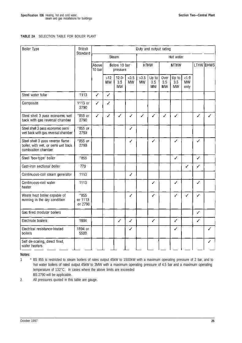
Specification 036 Section Two—Central Plant
TABLE 2A SELECTION TABLE FOR BOILER PLANT
Notes:
2.
* BS 855 is restricted to steam boilers of rates output 45kW to 1500kW with a maximum operating pressure of 2 bar, and tohot water boilers of rated output 45kW to 3MW with a maximum operating pressure of 4.5 bar and a maximum operatingtemperature of 132°C. In cases where the above limits are exceededBS 2790 will be applicable.All pressures quoted in this table are gauge.
October 1997 25
Heating, hot and cold water,steam and gas installations for buildings
Specification 036
Section Three—Pumping Equipment
3.1 CIRCULATING PUMPS
3.1.1 General
3.1.1.1 Values of the resistance to fluid flow of itemsof equipment, pipework and/or the total distributionsystem indicated in the contract documents areapproximate.
3.1.1.2 It shall be the responsibility of theContractor to verify these values and provide pumpscapable of delivering the required volume whenoperating against the actual total system resistance.
3.1.1.3 Pumps shall comply with the requirementsof BS EN 60335-2-51 : 1991, BS 4082 Parts 1 and 2and BS 5257, as applicable.
3.1.1.4 Pumps shall be 'type' tested in accordancewith the requirements of BS 5316 Part 1 and shall beselected to give the correct fluid flow rate. Unlessotherwise indicated, test certificates and performancecurves shall be submitted.
3.1.1.5 Unless otherwise indicated pumps and theirdrives shall be segregated such that failure of pumpseals shall not result in damage to drive motors.
3.1.1.6 All pumps except draining pumps shall beinstalled with a valve on suction and deliveryconnections.
3.1.1.7 Pumps shall be provided with anti-vibrationmountings and flexible connections where indicated.
3.1.1.8 The Contractor shall be responsible forproviding all dimensions and details to enable pumpbases to be set out.
3.1.2 LTHW AND MTHW HEATING AND DHWSSYSTEMS
3.1.2.1 Horizontal or vertical circulators shall beelectrically driven and of the following types:
a) Centrifugal type, close coupled, or withdirect or approved indirect drive and taperconnections where necessary on suction anddelivery ports. Direct drive pumps andmotors shall be mounted on a common bed-plate.
b) In-line pumps with connections of a differentsize to the main pipework may be usedsubject to the approval of the PM. Eccentricreducers shall be correctly fitted at suctionand delivery ports.
c) For LTHW and MTHW systems only,purpose designed pumps of the 'cannedrotor' or similar glandless type may be used.
d) For DHWS systems, pumps shall be asdescribed for LTHW and MTHW systemsimmediately above but shall have bodycastings of gunmetal.
3.1.2.2 Each circulating pump shall be installedwith a valve on the inlet and a valve on the outletconnections.
3.1.2.3 Shafts shall be corrosion resistant. Shaftseals shall be dripless mechanical or packed glandtype as indicated. Pumps with packed glands shallhave shafts hardened as necessary. Where a lanternring is fitted it shall be non-metallic. Gland packingmaterial and construction shall be suitable for theoperating conditions and shall be approved by the PM.Packed glands shall be provided with separate drippipes, run to discharge visibly over a tundish or waterdrainage gulley.
3.1.2.4 Bearings shall be either sleeve type withoiling ring and reservoir, or ball or roller type withgrease lubricator or sealed for life. The bearings shallbe outside the stuffing box and shaft seal.
3.1.2.5 Each floor-mounted circulating set shall beproperly levelled, bolted down and grouted-in, on abrick or concrete base provided by the Building
26 October 1997
Heating, hot and cold water,steam and gas installations for buildings
Specification 036 Section Three—Pumping Equipment
Contractor to details supplied by the Contractor. Baseheight to the underside of the pump shall be 300mmminimum. Anti-vibration mountings and flexibleconnections shall be provided as indicated. TheContractor shall ensure that the complete unit iseffectively balanced to eliminate noise and vibration.Belts, where fitted, shall be correctly aligned andtensioned.
3.1.2.6 Pressure gauges shall be connected to themain on each side of the circulator. Where duplicatepumps are provided the gauges shall be connected tothe common suction and delivery mains. The gaugesshall be provided with air venting facilities, flangedbacks, and shall be mounted at the same horizontallevel. In all other respects they shall be in accordancewith Clauses 9.2.1 to 9.2.3.
3.1.3 HTHW Heating Systems
3.1.3.1 Centrifugal pumps shall be of the typesdetailed in Clause 3.1.2.1(a) and shall comply with therequirements of Clauses 3.1.2.2 to 3.1.2.6 asappropriate.
3.1.3.2 Pumps shall have cast steel bodies, corrosionresistant steel shafts and nickel-iron impellers.Alternative materials suitable for the operatingconditions will be considered provided they are fullydetailed by the Contractor.
3.1.3.3 The pump construction and layout shallallow use of a standard mechanical shaft seal suitablefor the water temperature, and standard ball andsleeve bearings. Seal faces shall be selected to suit thewater condition (ie. with/without abrasive particles).
3.1.3.4 Inlet and outlet ports shall be flanged andprovided with taper connections if necessary.
3.2 BOILER FEED PUMPS
3.2.1 Other than for electrode boilers, feed pumpsshall be electrically driven centrifugal type, horizontalor vertical pattern, arranged for direct drive through aresilient coupling. Horizontal pattern pumps andmotors shall be mounted on a common bed-plate. Thepump sets shall be supported on brick or concretebases, or be integral with a packaged steam boiler. Allparts of the pumps in contact with condensate shall beof corrosion resistant material.
3.2.2 Feed pumps for electrode boilers shall beelectrically driven, and of the positive displacementscrew or gear type fitted with an integral pressurerelief valve.
3.2.3 Shaft seals shall be provided in accordancewith Clause 3.1.2.3.
3.2.4 Bearings shall be as specified in Clause3.1.2.4. Each bearing shall be housed in a pedestalseparate from the gland seal.
3.2.5 Inlet and outlet ports shall be flanged andprovided with taper connections. Each pump whennot supplied as an integral part of a packaged steamboiler, shall be mounted as specified in Clause 3.1.2.5.
3.3 CONDENSATE PUMPS AND RECEIVER SETS
3.3.1 Pumps shall be electrically-driven centrifugaltype, unless otherwise indicated, arranged in duplicatewith manual changeover. Pump casings shall be of castiron or gunmetal as indicated. Shafts shall becorrosion resistant and impellers shall be of gunmetal.
3.3.2 Design of the pumps and the installationshall be such that condensate at temperatures up to98°C can be handled without damage occurring due tocavitation.
3.3.3 Pumps may be of the horizontal or verticaltype, connected, direct coupled, or indirectlycoupled with vee-belt drive and facilities for belttensioning mounted on a common bed plate or chassis.
3.3.4 Shaft seals shall be provided in accordancewith Clause 3.1.2.3.
3.3.5 Bearings shall be as specified in Clauses3.1.2.4 and 3.2.4.
3.3.6 Inlet and outlet ports shall be flanged.
3.3.7 Condensate receivers shall be of heavygauge welded steel or copper construction, and shallbe supported on a steel base. Steel receivers shall bepainted internally and externally with two coats ofanti-corrosive solution (see Clause 5.6.1). Eachreceiver shall be complete with the following:
a) Bolted access cover
b) Condensate level gauge glass
c) draining cock or valve
d) Connections for condensate return andpump suction
e) Separate vent and overflow pipes not lessthan 40mm size and so arranged that thedischarge will avoid structural damage orinjury to personnel
f) High and low water level pump controls
October 1997 27
Heating, hot and cold water,steam and gas installations for buildings
Specification 036 Section Three—Pumping Equipment
g) Purpose-built support frame of mild steel,galvanised after assembly
h) Sheet lead pads fitted on the bearingsurfaces of all copper receivers.
3.3.8 Steam-powered pumping sets whereindicated shall be packaged units comprisingautomatic pump complete with inlet and outlet checkvalves, float, vented receiver and ancillary equipmentassembled into a frame. A flow counter device shallbe fitted to each pump.
3.4 SEMI-ROTARY HAND PUMPS
3.4.1 Semi-rotary hand pumps shall bemanufactured from materials suitable for theparticular requirements. Those for boiler house andplant room drainage shall be suitable for use with hotwater at temperatures up to 98°C.
3.4.2 For the drainage of oil storage catchpits,shaft seals of the 'O' ring pattern shall be used.
3.4.3 Pumps shall have a foot valve and strainerand be fixed securely in a position to allow for ease ofmanual operation.
3.5 OIL CIRCULATING AND OIL TRANSFERPUMPS
3.5.1 Oil pumps shall be electrically drivenpositive displacement screw or gear type or, for usewith BS 2869: Part 2 Class D oils, of centrifugal type,suitable for the viscosity and temperature of the gradeof oil to be pumped. An integral pressure relief valveshall be fitted to positive displacement pumps.
3.5.2 Pumps for transferring oil from a bulkstorage tank to a service tank shall be startedmanually and switched off automatically by means ofa float switch fitted in the service tank.
3.5.3 Each floor mounted circulating set shallcomply with Clause 3.1.2.5.
3.6 FIRE PROTECTION SYSTEM PUMPS
3.6.1 Pumps providing a water supply to asprinkler installation shall comply with therequirements of BS 5306: Part 2.
28 October 1997
Heating, hot and cold water,steam and gas installations for buildings
Specification 036
Section Four—Distribution Installation
4.1 TUBES AND PIPES 4.2 PIPEWORK JOINTS AND FITTINGS
4.1.1 Tubes and pipes used for LTHW, MTHW,HTHW, steam, condensate, DHWS and cold waterservices, shall be as indicated in Table 4B.
4.1.2 Tubes and pipes used for natural gas, LPG,oil fuel and fire protection services, shall be asindicated in Table 4C.
4.1.3 Steel pipework shall be ungalvanised withthe exception of the following which shall begalvanised:
a) Drain pipework.
b) Vent pipework.
c) Overflow pipework.
d) DHWS pipework as indicated.
e) Cold Water Service pipework.
f) LPG pipework (where indicated).
g) Fire protection system pipework (whereindicated).
4.1.4 Pipework designated as 'concealed' in Tables2 and 3 shall include all pipework in chases, ducts,service shafts, partitions, ceiling voids, floors etc. Itshall not include short lengths of pipework passingthrough the building structure.
4.1.5 Pipe 'risers' used for natural gas servicesinside multi-storey buildings (buildings more than 5storeys and over 20m high) shall not exceed DN100and shall be mild steel to BS 1387 or carbon steel toBS 3601 S or ERW 410 of wall thickness as indicated.
4.1.6 Polyethylene tubes for natural gas or LPGservices shall be for below ground application only,and shall not be exposed to daylight or to ultra-violetlight sources during transit and storage.
4.2.1 LTHW and MTHW Systems
4.2.1.1 Joints on galvanised pipework shall bescrewed.
4.2.1.2 The following LTHW pipework joints shallbe welded:
a) Concealed pipework.
b) Pipework over DN 100.
c) LTHW systems connected to MTHWinjection sets.
All other LTHW pipework may have screwed orwelded joints.
4.2.1.3 All MTHW pipework joints shall be shall bewelded.
4.2.1.4 Where screwed joints are allowed, the malecomponent shall be taper threaded to BS 21 and thejointing between them shall be PTFE tape to BS 7786unless otherwise indicated.
4.2.1.5 Threaded fittings shall be malleable castiron, banded or beaded pattern, manufactured inaccordance with BS 143 and 1256 and BS EN 10242,galvanised to match associated piping as necessary.
4.2.1.6 Butt welding pipe fittings shall comply withBS 1965.
4.2.1.7 Flanges for steel pipework shall be forgedsteel. Headers shall be of flanged steel tube withflanges welded on. Spare outlets shall be blankedwith bolted flanges.
4.2.1.8 At dismantling points and where thepipework is connected to an appliance, sphericalseated unions shall be used for pipework up to DN 50,and flanges shall be used for pipework DN 65 andabove.
October 1997 29
Heating, hot and cold water,steam and gas installations for buildings
Specification 036 Section Four—Distribution Installation
4.2.1.9 Flanges shall be raised face to BS 4504 Part3 Section 3.1, Tables 9. Exceptionally, where flangedconnections are made to existing equipment havingflanges of Imperial sizes, the flange shall be flat facedto BS 10, Table A for LTHW systems, and Table D forMTHW systems, appropriate to the temperature andworking pressure.
4.2.1.10 Where flanged connections are made tocopper alloy valves, with flat faced flanges to BS 4504:Part 3, Section 3.3, the raised face of the matingflange shall be removed and the resulting machinedsurface shall comply with the tolerances quoted in BS4504: Part 3.2.
4.2.1.11 Metric bolts of the correct diameter shall beused with flanges to BS 4504. Where Imperial boltsare unobtainable for use with existing Imperialflanges, Metric bolts shall be used as follows:
12* 14 16 18 18* 20* 22 24
Where bolts are marked thus * washers shall be fittedunder the bolt heads and nuts.
4.2.1.12 Flanged joints shall be made with gaskets toBS 4865: Part 1, or BS 3063 as appropriate. Theyshall be of a grade and thickness suitable for thetemperature, pressure and operating conditions of theservice and shall be approved by the PM.
4.2.1.13 Proprietary grooved pipe jointing systemsusing elastomeric seal rings may be used up to amaximum temperature of 95°C and a maximumpressure of 9.5 bar with the approval of the PM.These shall be suitable for the temperature, pressureand operating conditions of the service.Manufacturer's recommendations on pipe wallthickness, methods of groove forming, groovedimensions, seal materials and limiting operationalloads shall be followed. Piping ends shall be withinthe recommended tolerances and shall be free fromburrs and distortion.
4.2.2 HTHW Systems
4.2.2.1 Where galvanised pipework is used (to thedirection of clause 4.1.3) the joints shall be screwed.
4.2.2.2 Joints in pipelines and at fittings shall bewelded. Butt-welding pipe fittings shall comply withBS 1965.
4.2.2.3 Steel welding neck or slip-on boss flangesshall be used for connections to valves and atdismantling points.
4.2.2.4 Flanges shall be raised face and suitable forthe operating temperature and pressure selected fromthe appropriate tables in BS 4504: Part 3.1.Exceptionally, where flange connections are made toexisting equipment having flanges of Imperial sizes,the connecting flange shall be flat faced to BS 10Table E.
4.2.2.5 Where appropriate there shall be compliancewith Clauses 4.2.1.10 and 4.2.1.11.
4.2.2.6 Flanged joints shall be made with gasketsinside the bolt circle to BS 4865: Part 1, or BS 3063 asappropriate. They shall be of a grade and thicknesssuitable for the temperature, pressure and operatingconditions of the service and shall be approved by thePM.
4.2.3 Steam Systems
4.2.3.1 Joints in steam pipework up to DN50conveying steam at up to 3.5 bar and not concealed(Clause 4.1.4) may be either welded, or have taperthreads as Clause 4.2.1.4. All other joints shall bewelded.
4.2.3.2 Threaded fittings shall be malleable castiron to BS 143 and 1256 and BS EN 10242 or wroughtsteel to BS 1740.
4.2.3.3 Butt-welding pipe fittings shall comply withBS 1965.
4.2.3.4 At dismantling points and where pipeworkis connected to an appliance, bronze seated malleableiron unions shall be used on pipework up to DN50conveying steam at up to 3.5 bar. All otherconnections shall be flanged.
4.2.3.5 Flanges shall be suitable for the operatingtemperature and pressure and shall comply withClauses 4.2.1.10, 4.2.1.11, 4.2.2.3, 4.2.2.4 and 4.2.2.6as appropriate.
4.2.4 Condensate Systems
4.2.4.1 Joints in steel condensate pipework shallcomply with Clauses 4.2.3.1 to 4.2.3.5 as appropriate.
30 October 1997
Heating, hot and cold water,steam and gas installations for buildings
Metric Bolt (M)
Bolt Hole Diameter (Inches)
Specification 036 Section Four—Distribution Installation
4.2.4.2 Joints in copper condensate pipework shallbe made with compression fittings to BS 864 Part 2 orby brazing. Screwed joints may be used with the priorapproval of the PM outside buildings or where severalfittings are installed closely together in the condensatesystem.
4.2.4.3 Threaded fittings in copper pipework shallbe of copper alloy to BS 143 and BS 1256 and shall bethreaded to BS 61. Unions or flanges may be used forconnecting to traps, strainers and other items of plantand equipment.
4.2.4.4 Flanges for copper pipework shall be ofcomposite type to BS 4504: Part 3, Section 3.3comprising copper alloy inserts brazed to the tubewith loose steel locking rings. Flange connectionsshall comply with Clause 4.2.1.11 and 4.2.1.12 asappropriate.
4.2.5 Water Systems
4.2.5.1 All water systems shall comply with to LocalAuthority Regulations.
4.2.6 DHWS Systems
4.2.6.1 These shall be stainless steel, copper orgalvanised steel with stainless steel or copper dead-legs as indicated.
4.2.6.2 Joints on galvanised pipework shall bescrewed, except at dismantling points where they shallbe flanged.
4.2.6.3 Fittings for copper pipework up to andincluding DN50 shall be of the capillary orcompression type to BS 864: Part 2. Capillary fittingsshall be either lead-free solder ring or end feed type asindicated. Lead free solder shall be used on all hotand cold water service systems. Fittings shall beresistant to dezincification where recommended by theWater Company and as approved by the PM. Jointsover DN50 shall be brazed or flanged as Clause4.2.4.4.
4.2.6.4 Pipework shall be arranged to allow easydismantling. Dismantling points in copper pipeworkup to and including DN50 shall be unions, otherwisethey shall be flanged.
4.2.6.5 Where internal cold water services do notform part of the Works, the DHWS system shallterminate within 450mm of each sanitary fitting orrange of appliances.
4.2.7 Cold Water Services
4.2.7.1 These shall be stainless steel, polythene,PVC, other plastics, copper or galvanised steel asindicated.
4.2.7.2 Copper systems shall comply with Clauses4.2.6.3 and 4.2.6.4.
4.2.7.3 Fittings for stainless steel pipe shall bestainless steel capillary or compression types. Socketlength of capillary type straight couplings shall be toBS 864: Part 2. Compression fittings shall be of grade316 stainless steel.
4.2.7.4 Polyethylene and PVC, or other approvedplastics pipes, shall have compression fittings to BS864: Part 3 or solvent welded fittings to BS 4346: Part1. Where approved by the PM, mechanical joints toBS 4346: Part 2, or joints suitable for ABS or PBpipework may be used.
4.2.7.5 Galvanised steel systems shall comply withClause 4.2.6.2.
4.2.7.6 Cleaning and sterilisation shall be carriedout as specified in Clause 12.3.7.
4.2.8 Natural Gas Services
4.2.8.1 Installation, pipework, joints and fittingsshall be in accordance with IGE UtilizationProcedures IGE/UP/2.
4.2.8.2 Where pipework is to be buried in theground, the Contractor shall mark out the position ofthe trenches to be excavated and shall indicate whereconcrete is required for pipe supports. The trenchshall provide a minimum cover of 750mm. Where acommon excavation is made for gas pipes and electriccables, a minimum clearance of 300mm shall bemaintained between the two services. Depending onthe nature of the subsoil, and where required by thePM, the gas pipes shall be bedded and covered withsoft sand to a thickness as indicated.
4.2.8.3 Steel pipework buried in the ground shall beprotected against corrosion as indicated.
4.2.8.4 Iron pipework shall be slung and soundedbefore laying. An approved plunger or disc stoppershall be drawn through the pipework as the workproceeds.
4.2.8.5 Within buildings the Contractor shallarrange for dismantling points at intervals notexceeding 24m and at such other points as required by
October 1997 31
Heating, hot and cold water,steam and gas installations for buildings
Specification 036 Section Four—Distribution Installation
the PM. For this purpose unions shall be used onpipework up to DN50, and flanges on pipework DN65and above.
4.2.8.6 A minimum clearance of 150mm shall bemaintained between gas pipes and electric cables,conduits etc, in all internal installations and aboveground external installations.
4.2.8.7in 240.
Pipes shall be laid to a fall of not less than 1
4.2.9 LPG Vapour Distribution Systems
4.2.9.1 Pipework shall be steel, PE tube or copper.
4.2.9.2 Joints in steel pipework DN50 and undershall be welded, flanged or screwed. Joints in steelpipework DN65 and above shall be welded or flanged.
4.2.9.3 Joints in copper pipework shall be eithercompression type or silver soldered or brazed.
4.2.9.4 Joints in polyethylene tube shall be madewith clamped or compression fittings complying withClause 4.2.9.7 or may be fusion jointed to British GasCorporation Standard Specification BGC/PS/PL2.
4.2.9.5 Fittings for steel pipes shall be of steel.Flanges shall be suitable for the temperature andpressure as selected from the appropriate tables of BS4504: Part 3, Section 3.1, or from BS 10 whenconnection is made to existing equipment havingflanges of Imperial sizes. Bolting shall be to BS 4882.Flange connections shall comply with Clauses 4.2.1.10,4.2.1.11 and 4.2.1.12 as appropriate. Butt weldingfittings shall be to BS 1965. Socket welding andthreaded fittings shall be to BS 3799.
4.2.9.6 Fittings for copper pipes shall be of forgedbrass or gunmetal to BS 864. Compression fittingsshall only be used in accessible positions.
4.2.9.7 Fittings for polyethylene tube shall be ofgunmetal resistant to dezincification to British GasCorporation Standard Specifications BGC/PS/PL2 andBGC/PS/PL3.
4.2.9.8 The requirements of Clauses 4.2.8.2, 4.2.8.3,4.2.8.6 and 4.2.8.7 shall apply as appropriate.
4.2.10 Oil Fuel Systems
4.2.10.1 Steel pipework shall have welded jointsusing butt welding fittings to BS 1965. Joints andfittings for copper pipework shall comply with Clauses4.2.6.2 and 4.2.6.3, as appropriate, except that soft
solder fittings shall not be used and compressionfittings shall only be used where required to facilitatedismantling. Galvanised pipework shall not be used.
4.2.10.2 Protection of external buried steel pipeworkshall be as indicated. Where indicated a non-corrodiblesecondary containment system shall be provided inaccordance with Environment Agency requirements.
4.2.11 Fire Protection Systems
4.2.11.1 Fire protection systems shall comply withBS 5306: Parts 1 and 2 as appropriate.
4.2.11.2 Fittings used with galvanised pipework shallbe galvanised.
4.2.11.3 Where joints and fittings are threaded theyshall comply with Clauses 4.2.1.4 and 4.2.1.5.
4.2.11.4 Proprietary grooved pipe jointing systemsshall comply with the requirements of Clause 4.2.1.13.
4.2.11.5 Fittings to which Fire Brigade connectionswill be made shall comply with the requirements ofthe Fire Fighting Authority.
4.3 WELDING
4.3.1 Unless otherwise indicated steel pipeworkcomplying with BS 1387 or BS 3601 with diametersand wall thicknesses not exceeding DN200 and 20mmrespectively shall be welded in accordance with therecommendations in HVCA/JIB RecommendedPractice and Tests for Competency 1990 (Formerlyknown as TR/5), as modified below. Steel pipes oflarger diameters and greater thicknesses shall bewelded in accordance with BS 2971, BS 2640, or otherspecifications as indicated or approved by the PM.
4.3.2 Joint designs, welding procedures, weldercertification and production weld quality shall complywith the requirements as interpreted by the appointedInspection Body: see Section 12.
4.3.3 Unless otherwise indicated joint designs,welding procedures and welders' competency testsshall be as described in the Recommended Practiceand Tests. Prior approval shall be obtained to theinstallation of gusseted bends.
4.3.4 Welders shall hold current certificates ofcompetency validated by the appointed InspectionBody, or similar approved body. Welders withoutvalidated current certificates shall undertake therelevant standard tests, witnessed and certified by theappointed Inspection Body before commencing work.Welders with validated certificates who lack relevant
32 October 1997
Heating, hot and cold water,steam and gas installations for buildings
Specification 036 Section Four—Distribution Installation
welding work experience in the preceding 3 months,and other welders as directed by the PM, shallundertake the relevant tests witnessed and certifiedby the appointed Inspection Body before commencingwork.
4.3.5 Welders shall permanently identify each oftheir welds with their own marker which willwithstand site conditions without damaging system orcomponent performance. Methods of marking shall beapproved.
4.3.6 Welds in unconcealed LTHW and fireprotection system pipework shall be visually inspectedto BS 5289, and copies of the records shall be given tothe PM. Welds will be checked by the appointedInspection Body at the time the pipework is pressuretested. Where the appointed Inspection Body is notsatisfied, the welds shall be subjected to the non-destructive testing procedures described in Clause4.3.7.
4.3.7 Unless otherwise indicated welds in MTHW,HTHW, steam and gas pipework, and in LTHWpipework which is to be concealed, shall be subjectedto a programme of non-destructive testing inaccordance with the relevant Standards. The methodof testing shall be ultrasonic or radiographic inaccordance with BS 3923 or BS 2910 respectively, asapproved by the PM. Tests shall be carried out bycertified competent persons recognised by theappointed Inspection Body. Copies of the test reportsshall be given to the appointed Inspection Body andthe PM to permit full consideration whilst therelevant welds remain exposed. The NDT programmeshall include:
a) testing one of the first 5 production weldsmade by each welder.
b) testing 10% of the subsequent productionwelds made by each welder.
c) in the event of finding a faulty weld, at thediscretion of the PM, the testing of a further2 welds made by the relevant welder.
4.3.8 The welds to be tested in compliance withClause 4.3.7 shall be randomly selected by the PM.
4.3.9 Welds found to be defective shall be rectifiedto a standard complying with BS Class IIspecifications to the satisfaction of the appointedInspection Body. At the discretion of the PM,rectification work shall be carried out by different
welders. Welders with failure rates consideredexcessive by the appointed Inspection Body shall betaken off the Works at the discretion of the PM.
4.4 BRAZING
4.4.1 Copper pipework up to DN200 with wallthicknesses up to 4.5mm shall be brazed in accordancewith the recommendations in HVCA/JIBRecommended Practice and Tests for Competency 1990(Formerly known as TR/3), as modified below. Forother pipe sizes and wall thicknesses, brazing shall becarried out in accordance with BS 1723, or otherspecification as indicated or approved by the PM.
4.4.2 Joint designs, brazing procedures, brazercertification and production joint quality shall complywith the requirements as interpreted by the appointedInspection Body see clause 12.1.1. Section 12.
4.4.3 Unless otherwise indicated or approved fillermetal shall be AG2 to BS 1845.
4.4.4 Brazing procedures shall include auxiliaryheating for pipe sizes DN75 and larger, for solidcopper flanges, and in other circumstances whereexposure weather, wall thickness etc, indicate soundjoints will not be otherwise assured.
4.4.5 Brazers shall hold a valid certificate ofcompetency issued by the appointed Inspection Bodyor similar approved body. Unless otherwise indicatedthe Code of Practice TR/3 standard test piece will bethe accepted test of competency. Brazers withoutvalid certificates and those without relevant brazingwork experience within the preceding three monthsshall undertake the TR/3 test, witnessed and certifiedby the appointed Inspection Body, before commencingwork.
4.4.6 Brazers shall permanently identify each oftheir joints with their own marker which willwithstand site conditions without damaging system orcomponent performance. Methods of marking shall beapproved.
4.4.7 A proportion of the joints made by eachbrazer each day shall be cut out and subjected todestructive testing under the supervision of theappointed Inspection Body. In the event of finding afaulty joint a further 2 joints made by the relevantbrazer shall be cut out and tested. Joints shall beselected for test at the discretion of the PM up to thenumbers as indicated. Cutting out and consequentialrepair works shall be carried out by the contractor athis expense.
October 1997 33
Heating, hot and cold water,steam and gas installations for buildings
Specification 036 Section Four—Distribution Installation
4.4.8 Visual examination and non-destructivetesting of joints will be carried out by the appointedInspection Body during the system pressure tests.The test criteria shall be those stated in Code ofPractice TR/3.
4.4.9 At the discretion of the PM rectificationwork on faulty joints shall be carried out by differentbrazers. Brazers with failure rates consideredexcessive by the appointed Inspection Body shall betaken off the Works at the discretion of the PM.
4.5 ANCILLARY EQUIPMENT
4.5.1 Pipework Supports
4.5.1.1 Pipework shall be supported adequately insuch a matter as to permit free movement due tothermal expansion and contraction. Pipeworksupports shall be arranged as near as possible tojoints, and the spacings shall not exceed those given inTables 4 and 5. Where pipes are thermally insulatedthe insulation shall be carried through the support.Where there are two or more sizes of pipes, thecommon support spacings shall be those required bythe smallest bore pipework. Supports for natural gaspipework shall comply with the requirements of IGEUtilization Procedures IGE/UP/2.
4.5.1.2 Plastic pipework shall be continuouslysupported as far as possible. Where this isimpracticable the spacings of the supports shall notexceed those indicated in the appropriate tables inBSCP 312: Parts 2 and 3.
4.5.1.3 Branches from vertical pipework shall notbe used as a means of support for risers.
4.5.1.4 Brackets for mild steel pipework shall bemild steel or malleable iron with ferrous fixings.Brackets for copper pipework shall be brass orgunmetal with non-ferrous fixings.
4.5.1.5 Where pipework up to 50mm size is fixed tosolid walls, brackets may be of the screw-on or longshank built-in type, except where the walls areplastered when only the long shank built-in type shallbe used. For fixing to woodwork and lightweightpartitions or walls, brackets shall be screw-on patternand may be adjustable two-piece type. The detachablepart of a pipe clip shall be capable of removal withoutdisturbance of the fixing or adjacent pipes. Allowanceshall be made in the support for the thickness ofthermal insulation where required. Cast-iron and steelspigot and socket pipework shall be supported at eachjoint on mild steel angle or tee brackets embedded not
less than 115mm into walls. Pipework shall besecured to the brackets by bolts or mild steelstirrup bolts.
4.5.1.6 Brackets screwed to walls shall be securedby expanding plugs or other purpose designed fixingdevices; wooden plugs will not be accepted.
4.5.1.7 Pipework subject to expansion andcontraction and hung from supports shall besuspended on swivel hangers unless otherwiseapproved.
4.5.1.8 Hangers for horizontal pipework at highlevel shall be adjustable mild steel supported frommild steel angle or channel sections, supplied by theContractor, suitable for building-in or otherwisesecuring to the structure by the Building Contractor.Welding to the structure shall not be undertakenwithout the prior approval of the PM. Pipe rings shallbe of malleable cast-iron or fabricated steel, made inhalves and secured by bolts or screws. Alternatively,malleable iron hinged pipe rings may be used.Calliper hooks will not be accepted. Proprietarypipework suspension systems may be used with theapproval of the PM.
4.5.1.9 Where pipework is fitted in ducts ortrenches, or where DN65 or greater, supports shall beof the type indicated. Allowance shall be made forthermal insulation to be applied to the requirementsof Section 10. Load-bearing insulation at supportsshall be fitted by the Contractor at the time oferecting the pipework (see Clause 10.3.5).
4.5.2 Anchors
4.5.2.1 On mild steel pipework, mild steel anchorscapable of resisting the maximum stresses shall beprovided and preferably shall be welded to thepipework. Where it is not practicable to weld theanchors to the pipework, cast-iron chairs with at leasttwo wrought-iron stirrup bolts shall be used, the boltsto have sufficient thread to ensure an effective grip onthe pipe. For copper pipework the anchors shall beprovided by wide copper straps secured to thepipework in such a manner that the pipe is notdamaged. The Contractor shall supply, and fix inposition ready for building-in, all cleats, brackets andsteelwork required for anchor points. Steelwork intrenches or ducts to which anchors are attached shallbe hot-dip galvanised. Anchors shall have two coats ofaluminium paint.
34 October 1997
Heating, hot and cold water,steam and gas installations for buildings
Specification 036 Section Four—Distribution Installation
4.5.3 Expansion Devices
4.5.3.1 Provision for movement due to thermalexpansion and contraction shall be made by changesin direction of the pipework, by loops or by specialexpansion joints approved by the PM. Measures shallbe taken to prevent the movement of pipeworkcausing damage to thermal insulation.
Supports and guides shall be arranged to ensure thatmovement is taken up as intended. Where pipeworkis required to be pre-stressed, the extent of the coldpull shall be as indicated. Fixing bolts for flangedjoints shall not be used for taking up cold pullallowance.
4.5.3.2 Expansion joints may be of the articulatedor axial type as indicated and have screwed or flangedends as appropriate. Internal liners shall beincorporated if required, manufactured from acorrosion-resistant steel, or other approved materialappropriate to the duty, and designed to withstand thetest pressure of the system. Expansion joints shall becapable of not less than 2000 complete cycles ofmovement over the designed working range.
4.5.3.3 Expansion joints for angular movementsshall be provided with tie rods or hinges to take endthrust, and shall comply in general with Clause4.5.1.1.
4.5.3.4 Expansion joints shall be provided withexternal protection against damage where indicated.The method of protection shall be approved by thePM.
4.5.3.5 Expansion joints shall be installed so thatthey are not subjected to stresses other than those forwhich designed. Installation shall ensure joints are inthe free position at a temperature midway betweenthe high and low limits of normal service.
4.5.3.6 Expansion joints shall have guides to ensurethat all movements are taken up in the designedmanner. Expansion joints shall be installed inaccordance with the manufacturer's recommendations.On completion of installation and before heat isapplied to the system the Contractor shall obtaincertification that the installation is in accordance withthe manufacturers' instructions. Guides shall berigidly secured and allow freedom of movement forpipe expansion without excessive clearance.Lubrication points shall be provided where necessary.
4.5.4 Air Venting
4.5.4.1 Devices for air release shall be provided atall high points.
4.5.4.2 Air bottles for LTHW systems shall be madefrom DN50 tube approximately 230mm long fittedwith a cap and size 3/8 air cock; these shall be fittedto equal tees or have DN50 connections if the main islarger than DN50. Where an air bottle is fixed out ofreach a DN10 extension tube shall be run from thecap to within 1.5m of the floor, terminating with a size3/8 needle-seated globe valve or air cock.
4.5.4.3 Air bottles for MTHW and HTHW systemsshall be of welded construction. On pipework up toand including DN80 each bottle shall be manufacturedfrom DN50 tube 300mm long with a cap. Air bottleson pipework DN100 and over shall be manufacturedfrom DN100 tube each 380mm long with a cap. Allair bottles shall be complete with DN15 tube from thetop brought down to within 1.5m of the floor and fittedwith a DN15 lockable flanged globe valve. The openended outlet pipe from the valve shall discharge at aposition approved by the PM.
4.5.4.4 Automatic air vents, suitable for the systemtemperature and pressure, shall be used only whereindicated and have malleable iron, nodular iron,gunmetal or brass bodies, as indicated, with non-ferrous or stainless steel floats and guides and noncorrodible valves and seats. Each air vent shall havea lock-shield valve. Air release pipes shall be run todischarge at the nearest suitable visible safe point.
4.5.4.5 Air vent and air release pipes installedwhere freezing is likely to occur shall be insulated.
4.5.5 Emptying Down, Draining and Flushing
4.5.5.1 Steel pipework from drain valves or cocksshall be galvanised.
4.5.5.2 Drain valves or cocks shall be lockableexcept where prohibited by the Water Company.
4.5.5.3 In addition to the requirements of clauses4.5.5.4 and 4.6.12, for emptying purposes, 15mmminimum size drain cocks or valves, with hoseconnections, shall be fitted at all low points of LTHW,MTHW, DHWS and cold water systems.
4.5.5.4 Where a pipe dips under a door into anaccessible floor chase a 15mm plugged outlet shall befitted to LTHW, MTHW, DHWS and cold watersystems.
October 1997 35
Heating, hot and cold water,steam and gas installations for buildings
Specification 036 Section Four—Distribution Installation
4.5.5.5 For HTHW systems, drain points withflanged valves of the sizes indicated shall be installedat all low points. Valves shall be lockable needle-seated globe type.
4.5.5.6 In LTHW, MTHW and HTHW systems,where indicated, facilities shall be included to permitpre-commissioning cleaning of pipework. Thesefacilities shall include the following:
a) In systems, where pipework sizes are DN40to DN200 inclusive (other than those inwhich boiler flow and return headers arefitted with spare blanked connections), aflushing connection shall be fitted to thecommon flow from the boiler(s) and thecommon return to the boiler(s). Theseconnections shall be of the same size as thelargest pipe size of any sub-circuit.Additionally, at intervals not exceeding100m, an isolating valve immediatelypreceded by a drain valve, shall be includedin all the circuit pipework. The drain valvesshall be of the straight through lockabletype and shall be line size for pipework upto DN40 and DN50 otherwise.
b) For pipework sizes exceeding DN200provision shall be made for flexible or rigidlance water jetting. Flanged make-uppieces, three pipe diameters in length shallbe fitted at intervals not exceeding 100m tofacilitate access.
On completion of pre-commissioning cleaning, andbefore final filling, the flushing connections shall beblanked and the drain valves locked in the closedposition.
4.5.5.7 Steam and condensate mains shall begraded to fall in the direction of flow unless indicatedotherwise. The minimum gradient shall be 1 in 300.Drainage and relay points shall be provided at thelowest points in the mains. Drainage points and scalepockets shall consist of a short length of vertical tubeextending downwards from a tee on the main. Thediameter of the tube and the connection shall be notless than DN50 or the same diameter as the main.Pockets up to and including DN80 shall be not lessthan 230mm long and terminate in a screwed cap.Pockets DN100 and above shall be not less than300mm long and shall be flanged. The drainageconnection shall be taken from approximately one-third up from the bottom of the pocket to a strainerand steam trap set.
4.6 GENERAL
4.6.1 Unless otherwise indicated steel and copperpipework systems shall be designed and installed inaccordance with BS 806 or BS 1306 as relevant.
4.6.2 Where any of the services referred to in thissection require the connection of differently sizeditems, the Contractor shall be responsible forproviding and installing the adaptors.
4.6.3 Joints shall not be made in the thickness ofany wall, floor or ceiling, and pipework shall not beembedded in the structure of floors unless approved bythe PM. Where pipework passes through walls, floorsor ceilings, sleeves shall be provided. Pipeworkpassing through floors shall be provided withapproved floor and ceiling plates fastened securely tothe pipe. The sleeves shall be of the same material asthe pipe. Where a piped service penetrates astructure which is a fire barrier with a designated firedelay characteristic to BS 476: Part 22, the sleeveshall provide a fire stop to comply with the BuildingRegulations.
4.6.4 Fittings shall be of the same size as thetubes and pipes to which they are connected.Exceptionally where a fitting having the requiredoutlet is not of standard manufacture, the necessarysize reduction may be accomplished by the use of onebush for each connection.
4.6.5 Unless otherwise indicated, malleablefittings to BS 143 and BS 1256 shall be used asfollows:
a) Elbows to ISO Code Al shall be used inpreference to bends to ISO Code Dl.
b) Tees to ISO Code Bl shall be used inpreference to pitcher tees to ISO Code El.
4.6.6 Pipework shall follow the contours of walls.The clearance between pipework, fittings, lagging orflanges, and the wall or any other fixtures, shall benot less than 25mm.
4.6.7 Purpose-made bends or springs may be usedwhere it is necessary to deviate from a straight run innon-galvanised pipework. In galvanised pipeworkdeviations shall be formed from standard fittings.
4.6.8 Bends or springs in tubes of DN50 andabove shall be hot pulled and the tubes shall remaincircular after being set.
36 October 1997
Heating, hot and cold water,steam and gas installations for buildings
Specification 036 Section Four—Distribution Installation
4.6.9 Eccentric reducing sockets (ISO Code M3)shall be used where changes of bore are made in runsof nominally horizontal pipework to facilitate airventing and draining.
4.6.10 Before pipework is assembled, theContractor shall ensure that tubes and tube ends arefree from burrs and cutting dross. Tube ends shall becleaned thoroughly of dirt, rust, scale, paint, oil, etc(see also Clause 12.3.1). Open ends left during theprogress of work shall be closed temporarily withpurpose-made metal, plastics or wood plugs or caps, orblank metal flanges.
4.6.11 Entry and exit holes for pipework servicesfrom buildings shall be sealed and plugged. Forservice conditions below 60°C the sealant shall bemastic compound; above this temperature the sealantshall be silicone rubber.
Where pipework enters a building through a duct orhole which is considered by the PM to be too large forsuch treatment, a mild steel blanking plate not lessthan 6mm thickness shall be built into the walls of theduct or hole. The service pipes shall pass throughclearance sleeves (not less than 4 diameters in length)welded into the blanking plate. Annular spacesbetween pipes and sockets shall be sealed and pluggedas above.
4.6.12 Return headers, where indicated, shall bewelded with flanged connections and ends. Circuitisolating valves shall be connected direct to a verticalflanged stub on the top of the return header. On thecircuit side of the isolating valve a tee shall be fittedwith a vertical thermometer in the top reduced outlet.Each circuit return shall have an emptying pipeconnected and extended to a drain cock or valve belowthe level of the header. Headers shall be horizontaland thermometers, drain valves and circuit isolatingvalves shall each be arranged at common horizontallevels.
4.6.13 Flow headers where indicated shall bewelded with flanged connections and ends, andinstalled to prevent undue stresses on the boilers andthe connections.
4.6.14 Unless otherwise indicated both flow andreturn headers shall be provided with one spareflanged connection. These connections shall be ofsizes not less than the largest circuit connections tothe headers and they shall be sealed with blankflanges (see also Clause 4.5.5.6).
4.6.15 Metallic pipework systems shall be bondedto BS 7671 and BS 7430:1991 (Code of practice forearthing) see Clauses 11.7.1 and 11.7.2.
4.7 BELOW GROUND DISTRIBUTION PIPEWORK
4.7.1 Below-ground distribution pipework shallcomply with the following as indicated:
a) MOD (ex PSA) Standard Specification(M&E) No. 168: Thermally InsulatedUnderground Piping Systems for theConveyance of Steam, Hot and ChilledWater.
b) BS 7572:1992—Code of practice for thermallyinsulated underground piping systems.
c) BS EN 253:1991—Preinsulated bonded pipesystems for underground hot waternetworks.
d) BS EN 448:1995—Preinsulated bonded pipesystems for underground hot waternetworks. Fittings assemblies of steelservice pipes, PU thermal insulation andouter casing of high density polyethylene.
e) BS EN 488:1995—Preinsulated bonded pipesystems for underground hot waternetworks. Steel valve assembly of steelservice pipes, PU thermal insulation andouter casing of polyethylene.
f) BS EN 489:1995—Preinsulated bonded pipesystems for underground hot waternetworks. Joint assembly for steel servicepipes, polyurethane thermal insulation andouter casing of polyethylene.
4.8 THE ENVIRONMENTAL AGENCYREQUIREMENTS
4.8.1 The requirements of the Agency in respectof double-wall pipe systems shall be met as applicableto the particular installation. Outer casings shall beof non-corrodible material.
4.8.2 Oil storage tanks installed undergroundshall be double-skinned with GRP or plastics outerskin and interstitial leak detection systemincorporated where deemed necessary by the Agency.
4.8.3 The foregoing requirements shall apply toinstallations within Source Protection Zones. Allinstallations shall conform to those recommended inAgency Publications 2,5,8,15 and 19.
4.8.4 Agency shall be consulted prior to start ofinstallation of any buried oil pipeline or storage tankto establish final local requirements.
4.8.5 Plantroom and boiler room discharge waterarrangements shall comply with PPG 15.
October 1997 37
Heating, hot and cold water,steam and gas installations for buildings
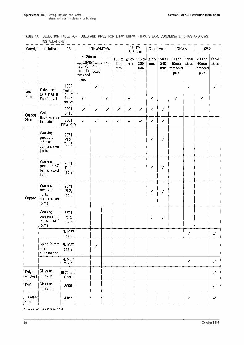
Specification 036 Heating, hot and cold water,steam and gas installations for buildings
Section Four—Distribution Installation
TABLE 4A SELECTION TABLE FOR TUBES AND PIPES FOR LTHW, MTHW, HTHW, STEAM, CONDENSATE, DHWS AND CWS
INSTALLATIONS
38 October 1997
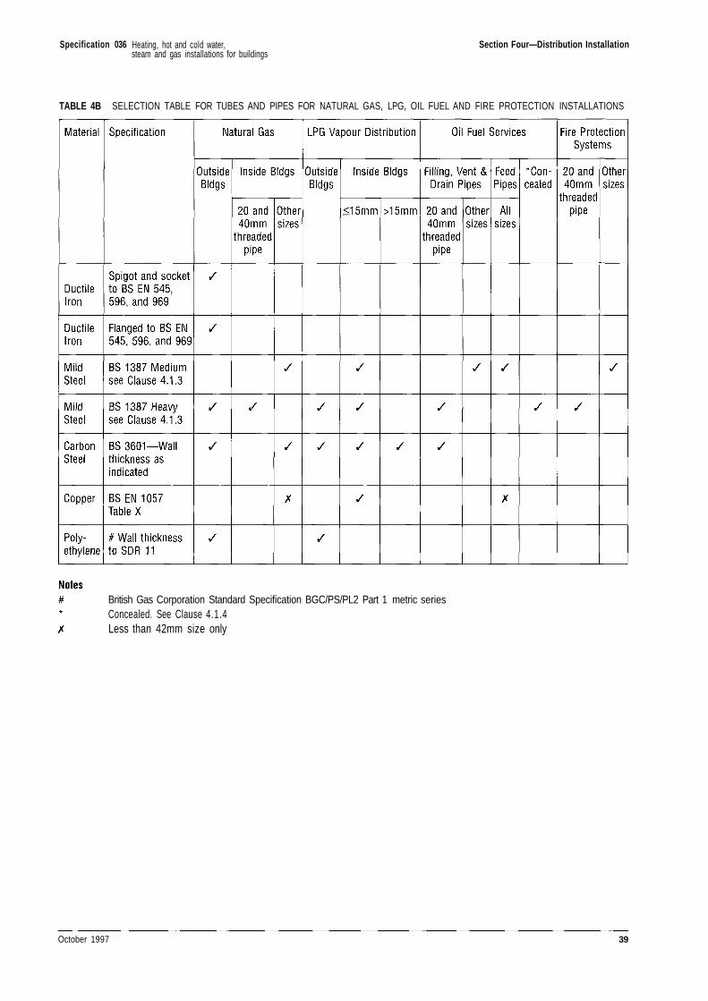
Specification 036 Section Four—Distribution Installation
TABLE 4B SELECTION TABLE FOR TUBES AND PIPES FOR NATURAL GAS, LPG, OIL FUEL AND FIRE PROTECTION INSTALLATIONS
British Gas Corporation Standard Specification BGC/PS/PL2 Part 1 metric seriesConcealed. See Clause 4.1.4Less than 42mm size only
October 1997 39
Heating, hot and cold water,steam and gas installations for buildings
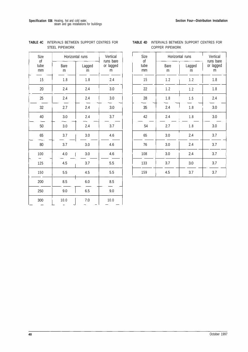
Specification 036 Section Four—Distribution Installation
TABLE 4C INTERVALS BETWEEN SUPPORT CENTRES FORSTEEL PIPEWORK
TABLE 4D INTERVALS BETWEEN SUPPORT CENTRES FORCOPPER PIPEWORK
Sizeof
tubemm
15
20
25
32
40
50
65
80
100
125
150
200
250
300
Horizontal runs
Barem
1.8
2.4
2.4
2.7
3.0
3.0
3.7
3.7
4.0
4.5
5.5
8.5
9.0
10.0
Laggedm
1.8
2.4
2.4
2.4
2.4
2.4
3.0
3.0
3.0
3.7
4.5
6.0
6.5
7.0
Verticalruns bareor lagged
m
2.4
3.0
3.0
3.0
3.7
3.7
4.6
4.6
4.6
5.5
5.5
8.5
9.0
10.0
Sizeof
tubemm
15
22
28
35
42
54
65
76
108
133
159
Horizontal runs
Barem
1.2
1.2
1.8
2.4
2.4
2.7
3.0
3.0
3.0
3.7
4.5
Laggedm
1.2
1.2
1.5
1.8
1.8
1.8
2.4
2.4
2.4
3.0
3.7
Verticalruns bareor lagged
m
1.8
1.8
2.4
3.0
3.0
3.0
3.7
3.7
3.7
3.7
3.7
40 October 1997
Heating, hot and cold water,steam and gas installations for buildings
Specification 036
Section Five—Calorifiers, Cylinders Cisterns andWater Tanks
5.1 CALORIFIERS
5.1.1 Storage calorifiers shall comply with BS 853Grade A or Grade B as indicated.
5.1.2 Non-storage calorifiers shall comply with BS3274 Type 2 or BS 853 Grade A as indicated.
5.1.3 Each calorifier shall have the followingprovided:
a) Safety valve.
b) Pressure gauge on the secondary side.
c) Thermometer on the secondary side.
d) Open vent pipe on systems open toatmosphere.
e) Thermostatic and high limit control.
f) Drain cock or tap, operated by a removablekey.
g) Graphite type bursting disc as appropriate.
h) Pressure gauge, syphon and cock on thesteam side of steam heated calorifiers.
j) Pressure gauge and cock on the primary sideof HTHW heated calorifiers.
5.1.4 Bursting discs to BS 2915 and BS 853 shallbe fitted to calorifier shells, and to all hot waterstorage calorifiers where the primary heating mediumis MTHW or HTHW. The rupturing pressure of thebursting disc and the set pressure of the safety valveshall be as indicated.
5.1.5 For BS 853 storage calorifiers where theprimary heating medium is MTHW or HTHW, thefollowing shall be included where indicated:
a) An automatic fast response isolating valve,operated by excess secondary pressure, inthe primary flow pipework.
b) A check valve in the primary returnpipework.
5.1.6 The discharge arrangements from safetyvalves and bursting discs shall comply with therequirements of Clauses 7.2.3 and 7.2.4.
5.1.7 Heating surfaces shall be formed fromcopper tubes. Shells of non-storage calorifiers shall beof cast-iron or mild steel. Shells of non-storagecalorifiers on DHWS systems shall be galvanised aftermanufacture, or copper, as indicated.
5.1.8 Shells of storage calorifiers shall be mildsteel galvanised after manufacture, mild steel linedwith copper, or copper as indicated. Sacrificial anodesshall be provided as indicated.
5.1.9 Where calorifier shells are galvanised thecopper tubes shall be tin-coated on the secondary side.
5.1.10 The tube plate and tube chest cover shall beprovided with a lifting ring where the flange diameteris 600mm and over. Provision shall be made for easyremoval of the heating surface from the body.Sufficient set-bolts shall be provided to enable thetube nest to be withdrawn without breaking the jointbetween the tube plate and the chest cover plate.
5.1.11 Flange drillings shall be uniform, as far aspracticable, to permit interchange of tube assemblies.Spare tube and plate assemblies shall be suppliedwhere indicated.
5.1.12 Horizontal calorifiers shall be supported onbrick or concrete piers and/or mild steel cradles.Vertical calorifiers shall be provided with purposemade steel support frames. Sheet lead pads shall befitted on the bearing surfaces of all copper calorifiers.
October 1997 41
Heating, hot and cold water,steam and gas installations for buildings
Specification 036 Section Five—Calorifiers, Cylinders Cisterns and Water Tanks
5.1.13 On installations of two or more calorifierseach safety vent may be connected into a commonvent pipe through a three-way cock (see Clause 7.8.7)so arranged that no calorifier can be isolatedsimultaneously from the open vent pipe and the freeoutlet. Vent pipes shall rise continuously and not beobstructed by a valve or any other item.
5.1.14 The secondary side of multiple DHWSstorage vessels shall be connected in parallel asindicated. Unless otherwise indicated each vesselshall be independent and complete with isolatingvalves to permit partial service to be maintained whenthe isolated vessel is out of service. Isolated sections ofpipework shall be provided with drain cocks inaccordance with clause 7.12.3.
5.2 CYLINDERS
5.2.1 Direct cylinders shall be as follows:
a) Galvanised mild steel cylinders shall complywith BS 417: Part 2 grade A or grade B, asindicated.
b) Copper cylinders shall comply with BS 699grade 1 or grade 2, as indicated. Handholesshall be not less than 150mm diameter andshall be provided with covers secured bystuds and nuts.
5.2.2 Indirect cylinders shall comply with BS 1566:Part 1 Grade 2. Handholes shall be fitted as detailedin Clause 5.2.Kb).
5.2.3 Cylinders larger than or for a greaterworking head than those covered by Clauses 5.2.1 and5.2.2 shall be constructed in accordance with BS 853.Such cylinders/storage calorifiers shall be providedwith a manhole of the size and type specified in BS 853unless a bolted top is fitted. All mild steel indirectcylinders shall be provided with a bolted top.Sacrificial anodes shall be provided as indicated.
5.2.4 Manhole covers shall be secured with studsor bolts and nuts, or with one or more externalbridge(s). Joints for handhole and manhole coversshall be made with an approved re-usable jointingmaterial.
5.2.5 Supports for mild steel and copper cylindersshall be as detailed in Clause 5.1.12.
5.2.6 Bubble top calorifiers and cylinders shallcomply with BS 853 where applicable.
5.3 ELECTRICALLY HEATED HOT WATERSTORAGE VESSELS
5.3.1 Where an electrical immersion heater isfitted into a storage calorifier or cylinder for thesupplementary heating of domestic hot water, orwhere electrical heating is used in any vessel for thispurpose, the following items shall be included:
a) A safety valve on the shell, or adjoiningpipework immediately adjacent to the shell.The set pressure shall be in accordance withBS 853.
b) An open vent pipe fitted in accordance withClause 5.1.13.
c) A thermostat acting on the power supply tomaintain the water temperature within anadjustable setting between 50°C and 80°C.
d) An independent high limit cut-out device setto isolate the power supply at a watertemperature 10°C above the thermostatsetting. This device shall be arranged formanual reset.
5.4 PLATE HEAT EXCHANGERS
5.4.1 Plate heat exchangers shall comprisecorrugated plates with primary and secondary fluidports, assembled with ring gaskets and plate seals,mounted on a frame having end-support plates, rackand end posts, and clamped together with long boltsand tube washers acting on loose end pressure plates.
5.4.2 End plates shall carry screwed connectionsfor piping up to DN50 and flanged connections forpiping DN65 and above.
5.4.3 Gasket material shall be entirely suitablefor the fluids to be used and shall be Water ResearchCentre approved.
5.4.4 Plates shall be fabricated in Grade 316stainless steel or other approved material.
5.4.5 The assembly and frame members shall belocated on concrete plinths as indicated.
5.5 CISTERNS AND COLD WATER TANKS
5.5.1 Cisterns and cold water storage tanks shallbe of the following types as indicated:
a) Welded or riveted mild steel
b) Pressed steel sectional
c) Thermo-plastics for cisterns
42 October 1997
Heating, hot and cold water,steam and gas installations for buildings
Specification 036 Section Five—Calorifiers, Cylinders Cisterns and Water Tanks
d) Glass reinforced plastics (one piece)
e) Glass reinforced plastics (sectional)
f) Aluminium/galvanised steel, lined with abutyl rubber membrane. All potable waterstorage vessels shall comply with the WaterByelaws.
5.5.2 Mild steel cisterns shall be galvanised typeto BS 417: Part 2 Grade A, sacrificial anodes beingprovided where indicated. Thermo-plastics cisternsshall comply with BS 4213. Pressed steel sectionaltanks, glass reinforced plastics and butyl rubber linedcisterns shall be approved by the PM.
5.5.3 Each cistern shall be provided with a loosecover formed in sections not exceeding 2m long and1m wide. Covers for steel cisterns shall be formedfrom 1.6mm thick galvanised mild steel with flangededges to the sections. Covers for plastics and butylrubber lined cisterns and tanks shall be of the samematerial as the cistern or tank body. The terminationof vent pipes into cisterns and tanks shall permit theeasy removal of the covers.
5.5.4 Pressed steel tanks shall be of the externallyflanged type and complete with purpose-made coversand all necessary tie rods. Galvanised mild steelcisterns and pressed steel tanks shall be paintedinternally with two coats of an approved bituminoussolution.
5.5.5 Each cistern or tank shall be fitted with a floatoperated valve as specified in Clause 7.8.8. These valvesshall be of the sizes indicated and suited to the pressureavailable. Cisterns and tanks shall be installed inpositions that allow easy access for maintenance.
5.5.6 Warning and/or overflow pipes shall be twicethe bore of the ball-float valve fitted or 32mm size,whichever is the greater. Pipes shall be run todischarge outside the building.
5.5.7 Connections to mild steel cisterns and tanksshall be made by means of bosses, screwed flanges orpads and studs. Connections on mild steel cisternsshall be welded before galvanising. Flanges shallcomply with the requirements of Section 4. Openingsfor connections to other tanks may be cut on site andthe connections made with back-nuts and plasticswashers. For thermo-plastics and butyl rubber linedcisterns and tanks, connections shall be fitted inaccordance with the manufacturer's recommendations.Flanged connections may be used on modular glassreinforced plastics tanks and cisterns.
5.5.8 Unless otherwise indicated supports forcisterns and tanks will be provided by the BuildingContractor. Where the Building Contractor isresponsible for cold-water services he will supply andfit the cold-water storage cistern for domestic andsanitary purposes and will connect the cold-watersupply to all ball-float valves.
5.5.9 Cisterns and tanks shall be labelled asindicated on site by the PM.
5.5.10 Multiple cold water storage tanks shall beconnected in series complete with by-pass, or parallelas indicated. Unless otherwise indicated each tankshall be independent and complete with isolatingvalves to permit partial service to be maintained whenthe isolated tank is being cleaned. Isolated sections ofpipework shall be provided with drain cocks inaccordance with clause 5.1.14.
5.6 FEED/EXPANSION AND SPILL VESSELS FORBOILER INSTALLATIONS
5.6.1 These shall be constructed in accordancewith the requirements of BS 417: Part 2, BS 1563 orBS 1564, as appropriate. Steel tanks shall begalvanised. Tanks shall be internally and externallyfinished with corrosion resistant coatings of approvedspecification. Tank covers shall be close fitting but notair-tight. Floating blankets or other means ofpreventing water aeration shall be provided asindicated.
5.7 BOILER FEED TANKS (HOTWELLS) FORSTEAM BOILERS
5.7.1 Tanks shall be constructed from Austeniticstainless steel or carbon steel as indicated. Tanksshall be covered but adequately vented. Whereindicated, the water temperature in the tank shall bemaintained at 80°C by direct steam injection. Carbonsteel tanks shall be painted internally to clause 5.5.4.Feed tanks shall be insulated; thermal insulation shallbe in accordance with Section 10.
5.8 SLOWDOWN TANKS FOR STEAM BOILERS
5.8.1 Blowdown tanks shall be constructed aspressure vessels to BS 5500 Category 3. Designpressure shall not be less than 25% of the maximumpermissible working pressure of the boiler(s), andshall ensure that flash steam is vented safely. Tanksshall be painted internally and externally as Clause5.5.4.
October 1997 43
Heating, hot and cold water,steam and gas installations for buildings
Specification 036
Section Six—Space Heating Equipment
6.1 RADIATORS
6.1.1 Unless otherwise indicated radiator heatingsystems shall operate at temperatures not exceeding95°C. Radiators shall be of the types, ratings anddimensions indicated, and they shall be manufacturedand tested in accordance with the requirements of BSEN 442-1. Cast-iron radiators shall be free from scaleand sand. Steel radiators shall be fabricated fromsteel sheet welded at the seams and strengthened byspot welding between waterways; they shall be freefrom distortion, have pressings which are regular incontour, and be uniform in appearance. The radiatorheating surface provided in any room shall be not lessthan the aggregate indicated. Radiators shall besupplied without feet unless otherwise indicated andbe finished with one coat of primer before leaving theworks.
6.1.2 The positions and heights above floor of allradiators shall be confirmed with the PM. Aminimum clearance of 75mm shall be providedbetween the floor and the underside of any pipeserving a radiator. The minimum clearance betweenthe floor and the underside of a radiator shall be150mm. Radiators shall be kept 40mm clear of wallswhen supporting brackets and stays are built-in,otherwise the clearance shall be in accordance withthe manufacturer's standard bracket details. ForLTHW installations, radiators shall be provided withvalves on the flow and return connections as detailedin Section 7.5. An air vent shall be fitted at the top ofeach radiator.
6.1.3 Radiators shall be supported on bottombrackets and top stays or purpose-designed brackets tosuit the type of radiator; the supports may be of thetwo-piece adjustable pattern. Where used on masonrywalls they may be either built-in or plugged andscrewed to the wall face. Where the masonry wall hasan internal lightweight structural facing, the radiatorsupports shall be approved.
6.1.4 Supports for cast-iron and steel panelradiators fixed direct to lightweight partitions shall beapproved before installation.
6.1.5 Supports for cast-iron and steel column typeradiators against lightweight partitions shall bedesigned to transmit the weight to the floor and shallbe screwed to or built into the floor; top stays shall beapproved.
6.1.6 Where radiators are fed by a straight sectionof pipework which is beneath the radiators and ismore than 10m long, the radiator brackets shall be ofthe suspended pattern or other approved typedesigned to permit free movement due to expansionand contraction of the pipework. (Pipe sets of under225mm shall be deemed straight pipework).
6.1.7 Cast-iron column radiators up to 20 sectionslong shall have two bottom brackets and one top stay.Radiators more than 20 sections long shall have anadditional bottom bracket and top stay for eachincrement of up to 20 sections in length. Steel columnradiators shall be supported in accordance withmanufacturer's recommendations.
6.1.8 Cast-iron panel radiators up to 1.5m longshall have two top and two bottom brackets. An extrapair of brackets shall be provided for each incrementof up to 1.5m in length. Steel panel radiators shall besupported in accordance with manufacturer'srecommendations.
6.1.9 Where radiators with feet are specified andthe floor finish is of a material likely to be damaged,the radiators shall stand on 12mm thick hardwoodboards supplied by the Building Contractor.
6.1.10 The Contract shall include taking downradiators once after initial installation for paintingand for re-fixing.
6.1.11 Existing radiators to be disconnected and re-fixed in the same or new positions shall be thoroughlywashed out, wire brushed and re-painted as necessary.
44 October 1997
Heating, hot and cold water,steam and gas installations for buildings
Specification 036 Section Six—Space Heating Equipment
6.2 CONVECTORS
6.2.1 Convectors shall be of the types, ratings anddimensions indicated. For natural convectors themanufacturer's declared ratings shall have beenobtained from tests in accordance with BS EN 442-1.For fan convectors the manufacturer's declared ratingsshall have been obtained from tests in accordance withBS 4856: Part 1.
6.2.2 Unless otherwise indicated heater elementsshall be enclosed in casings purpose-made by theconvector manufacturer. The casings shall have airinlet openings at the bottom and outlet grilles fittedwith internal dampers operated by lever or knob onthe outside of the casing. The casings shall be of mildsteel sheet not thinner than 1.25mm suitablystiffened, with removable front panels secured withpermanent fixings or captive screws. The casingsshall be free from rough edges and shall be treatedwith a rust inhibitor and finished with stove primer.
6.2.3 The elements shall be of copper or bronzetubes fixed securely to the flow and return headerswith non-ferrous fins not thinner than 1mm unribbed(0.2mm ribbed) bonded to the tubes. The fins shall befree from sharp edges and corners. Copper tubes shallmeet the test requirements of BS 2871 Part 3.
6.2.4 The positions and heights above floor ofconvectors shall be agreed with the PM. Whererecessed or built-in convectors have been specified, theContractor shall supply full details of the openingsand of any fixings or framing required.
6.2.5 Wall-mounted convectors shall be secured byscrews or bolts passing through holes in the back plateor frame of the unit, and a resilient gasket shall beinserted between the edges of the back panel and thefinishes at the sides and top. A minimum clearance of75mm shall be provided between floor and any pipeserving a wall-mounted convector. Two supports shallbe provided for each wall-mounted convector notexceeding 1.25m long and three supports for eachconvector longer than 1.25m.
6.2.6 Convectors for LTHW and MTHW systemsshall be provided with air cocks accessible from thefront or side without dismantling the casings. Thedischarges from air cocks on MTHW convectors shallbe arranged to ensure no risk of injury to operatives.
6.2.7 Convectors on LTHW and MTHW systemsshall be provided with union valves having heatinsulated handwheels on the flow connections, andunion valves with lock-shields on the returnconnections.
6.2.8 Steam and HTHW convectors shall be fittedwith valves and equipment in accordance with Section6.6.
6.2.9 The motor controllers for fan convectorsshall be integral with the convector casings, andmotors shall be resiliently mounted. The noise levelsresulting from their operation shall not exceed theNoise Ratings as indicated.
6.2.10 Air filters for fan convectors shall be of theopen-cell plastics cleanable type and easily removable.They shall have an average arrestance of not less than80% in accordance with BS EN 779 : 1992.
6.2.11 Gas-fired convector heaters shall be asindicated.
6.3 CONTINUOUS PERIMETER HEATING
6.3.1 Perimeter heaters for LTHW heating shallbe of cast-iron or steel, radiant or combined radiant/convection types, or steel-encased finned-tubeconvection type.
For MTHW they shall be steel-encased finned-tubeconvection type.
Units shall be of the rating and dimensions indicated.The manufacturer's declared ratings shall have beenobtained from tests in accordance with BS EN 442-1.
6.3.2 Heaters shall be complete with all ancillaryitems such as internal and external cover strips,dummy sections, valve boxes etc so that each runpresents a continuous unbroken appearance. Whereindicated the casings shall incorporate provision foraccommodating other services. Additionally, controldampers and sound baffles between rooms shall beprovided where indicated. The positions, lengths andheights of the heaters shall be agreed with the PM.
6.3.3 A gasket as specified in Clause 6.2.5 shall beprovided at the back of each heater.
6.3.4 Finned-tube convection type heaters shallhave removable front plates to provide access forcleaning. The elements for LTHW shall be asspecified in Clause 6.2.3. For MTHW the elementsshall be steel pipework with steel fins.
6.3.5 Copper connecting pipework between theelements of continuous perimeter convectors forLTHW shall have capillary or compression joints tosuit the finned elements. The copper tube shall be ofthe same grade and diameter as the element tube.
October 1997 45
Heating, hot and cold water,steam and gas installations for buildings
Specification 036 Section Six—Space Heating Equipment
6.3.6 Expansion devices and guides as detailed inSection 4 shall be fitted into the connecting pipe asrequired.
6.3.7 Perimeter heaters on LTHW and MTHWsystems shall be provided with air cocks in accordancewith Clause 6.2.6, and valves in accordance withClause 6.2.7.
6.4 RADIANT PANELS, STRIPS, CEILINGS ANDFLOORS
6.4.1 Radiant panels and strips shall be of theratings and dimensions indicated. The ratings shallhave been obtained from type tests. For LTHW andMTHW systems radiant panels shall have mild steelor cast-iron grid-type waterways (free from scale andsand). The waterways shall be shaped to provide asurface affording intimate contact with steel plates ofnot less than 2mm thick secured to present acontinuous face. Alternatively, the waterways may beformed from mild steel tube welded continuously tothe surface plate. For LTHW systems, copper tubewaterways (with aluminium or steel face plates) willbe acceptable.
6.4.2 For steam and HTHW systems the steam orwaterways shall be of mild steel tube, complying withBS 1387 'Heavy', welded to the surface plate whichshall be not less than 2mm thick.
6.4.3 Surface plates shall be smooth and free fromdistortion. Where connections pass through the sidesof a panel they shall be sealed effectively. The spacebetween the edges of a panel and the wall or ceilingsurface to which the panel is to be attached shall becompletely sealed.
6.4.4 Radiant strips shall have rigid face plates ofaluminium or mild steel not less than 1mm thick,secured to single or multiple waterways of mild steeltube in such a manner as to provide adequate heattransmission to the face plate. Tubes for steam orHTHW systems shall be of mild steel complying withBS 1387 'Heavy', with welded joints. Each radiantstrip shall be assembled in a continuous unbrokenlength.
6.4.5 Radiant panels and strips shall be arrangedhorizontally, vertically or inclined, as indicated, andsuspended from purpose-designed hangers, the pointsof support being in accordance with the maker'srecommendations. Where arranged horizontally theyshall be installed with a fall of not less than 1 in 200.
6.4.6 Where radiant panels or strips are to befixed to walls or ceilings, or are suspended to provideradiation from one side only, thermal insulationhaving a transmittance not greater than 1.4W/m2Kshall be incorporated between the face plate and aback cover plate, or fixed securely to the back face ofthe radiant surface.
6.4.7 For LTHW and MTHW systems flush typeair vents shall be fitted at the highest point of panelsmounted on walls. Panels supported on ceilings shallbe arranged to vent air through the connectingpipework. Panels and strips for LTHW and MTHWsystems shall have union valves with heat insulatedhand-wheels on flow connections and union valves withlock-shields on the return connections. Steam andHTHW radiant panels and strips shall be fitted withvalves and equipment in accordance with Section 6.6.
6.4.8 Radiant/convective ceilings or floors shall beas indicated.
6.4.9 Gas-fired radiant heaters, either individualunits or purpose-designed integral systems shall be asindicated.
6.5 UNIT HEATERS
6.5.1 The rated capacity and operating conditionsof unit heaters shall be as indicated. Themanufacturer's declared ratings shall have beenobtained from tests in accordance with BS 4856: Part 1.
6.5.2 Unit heaters shall have adjustable self-locking louvres. The casings shall be of sheet metal.Heater batteries shall be of the following types:
a) Copper tubes with non-ferrous gills or fins,fitted into copper or bronze headers;
b) Copper tubes with non-ferrous gills or fins,fitted into steel headers;
c) Mild steel tubes with mild steel gills or fins,fitted into welded steel headers, the wholesuitably protected against corrosion. Themethod of protection shall be approved bythe PM
6.5.3 Copper tubes specified in Clause 6.5.2 shallmeet the test requirements of BS 2871: Part 3.
6.5.4 The gills or fins shall be bonded to thetubes. Ample provision shall be made for expansion ofthe heater battery within the casing.
6.5.5 Fan impellers shall be of robust construction,balanced statically and dynamically, and attached toobviate any risk of detachment while the fan is
46 October 1997
Heating, hot and cold water,steam and gas installations for buildings
Specification 036 Section Six—Space Heating Equipment
running. Fan guards shall be fitted. The noise levelsresulting from their operation shall not exceed theNoise Ratings indicated.
6.5.6 The discharge air temperature shall notexceed 50°C.
6.5.7 Motors shall be mounted resiliently on theheater casings on rubber or other approved anti-vibration material.
6.5.8 The type and method of automatic control ofthe unit heaters shall be as indicated.
6.5.9 Heaters shall be provided with two or morepoints of suspension and shall be so suspended thattheir direction of discharge can be altered.
6.5.10 Heaters shall be designed and positioned topermit easy cleaning and dismantling.
6.5.11 Unit heaters on LTHW and MTHW systemsshall be provided with union valves having heat-insulated handwheels on the flow connections, andunion valves with lock-shields on the returnconnections. Steam and HTHW unit heaters shall befitted with valves and equipment in accordance withSection 6.6.
6.6 EQUIPMENT FOR STEAM AND HTHWHEATING APPLIANCES
6.6.1 Each heating appliance on a steam systemshall be provided with a globe valve on the inletconnection complying with Clauses 7.10.3 and 7.10.5.The outlet connection shall be provided with astrainer, check valve and steam trap set together witha globe or fullway valve as indicated. Dirt or scalepockets and sight glasses shall be installed whereindicated.
6.6.2 The flow and return connections to eachheating appliance on an HTHW system shall beprovided with valves complying with Clauses 7.8.3 and7.9.3.
6.7 SURFACE TEMPERATURES
6.7.1 Where space heating equipment is locatedwithin 2 metres of floor level, (or is otherwise normallyaccessible by occupants), the equipment shall beprotected by approved screens where surfacetemperatures exceed 95°C.
October 1997 47
Heating, hot and cold water,steam and gas installations for buildings
Specification 036
Section Seven—Valves, Taps and Cocks
7.1 GENERAL 7.2 SAFETY AND RELIEF VALVES
7.1.1 Unless otherwise indicated copper alloyshall mean one of the alloys listed in BS 5154 suitingthe particular application.
7.1.2 Gland packing, plug lubricants etc. shall besuitable for the application. For potable watersystems, materials shall comply with the requirementsof the Water Company. Exfoliated graphite packingshall not be used when in contact with steelcomponents.
7.1.3 Valves shall be easily accessible. Valvesfitted in horizontal pipework or to equipment withhorizontal connections, shall be installed with thevalve spindle vertically upwards unless otherwiseagreed by the PM. Check valves shall be installed inaccordance with the manufacturer's recommendations.
7.1.4 Where indicated, valves or cocks shall belockable, with purpose-made locking devices which donot impede the fast closure of the valve where that isnecessary. The locking device shall remain attachedto the valve in both open and closed position. Valvingto boilers flow and return connections shall be toclauses 30.1 and 30.2 of BS 759: Part 1. Where theadditional valves are installed and are separated by alength of pipe, this length shall have a drain cock andair vent.
7.1.5 Where modifications or extensions toexisting services are to be carried out, all valves whichare to be removed and re-fixed shall be overhauledthoroughly, with glands and seals renewed, all to thesatisfaction of the PM.
7.1.6 Copper alloy valves for mains water andHWS systems shall be resistant to dezincification.
7.1.7 Valves for the services in this Specificationshall be in accordance with Table 7A and as indicatedin Schedule 1.
7.2.1 Safety and relief valves shall meet therequirements of the appropriate BS for the boiler,calorifier or pressure equipment to which they areconnected, and they shall be suitable for the operatingconditions of the system. They shall be of the totallyenclosed spring-loaded type with padlock.
7.2.2 Safety and relief valves in LTHW and steaminstallations shall have discharge connections of sizesas indicated. Where any low point occurs in thedischarge pipework it shall be fitted with a DN15waste pipe carried clear of the insulation for drainage.
7.2.3 In MTHW and HTHW installations thesafety and relief valve discharge connections anddischarge arrangements shall not impede safe two-phase discharge at the intended rate.
7.2.4 Safety and discharge pipework for hot watersystems shall be laid with a continuous downwardgradient.
7.2.5 Discharge and waste pipes shall terminateat visible and safe positions to be agreed with the PM.Connections to drains shall be provided as indicated.
7.3 PRESSURE REDUCING VALVES
7.3.1 Valves shall be of the following types:
a) Valves for reducing the steam pressure toapparatus not designed to withstand themaximum pressure of the high-pressure lineshall be of an approved spring-loaded pilot-operated type.
b) Where apparatus on the low-pressure side iscapable of withstanding the maximumpressure of the high-pressure line, valvesmay be of the single-seated spring-loadeddiaphragm type.
48 October 1997
Heating, hot and cold water,steam and gas installations for buildings
Specification 036 Section Seven—Valves, Taps and Cocks
c) Bodies of valves up to and including DN50shall be of bronze or nodular iron, asindicated, and have threaded endconnections to BS 21. Valves DN65 and overshall have bodies of steel or nodular iron toBS 2789, as indicated, with end connectionsflanged to BS 4504: Part 3 or BS 1560.Valve seats and discs shall be of nickel-alloyor stainless steel and shall be renewable.Each valve shall be capable of maintaining areduced outlet gauge pressure within35mbar of the set pressure and shall beinstalled with an excess pressure protectionvalve or safety valve on the low-pressureside.
7.3.2 Each reducing valve shall be installed withan isolating valve and strainer or separator asrelevant and, where indicated, a pressure gauge onthe high-pressure side. The strainer shall include astainless steel screen on mesh size as recommended bythe reducing valve manufacturer. A pressure gaugeshall be fitted on the downstream side of safety valvesor excess pressure protection valves. Pressure gaugesshall be mounted on mild steel syphons with bronzeisolating cocks.
7.4 THERMOSTATIC CONTROL VALVES
7.4.1 Valves fitted to appliances other thanradiators, shall have bodies of gunmetal, bronze, cast-iron or steel as indicated. The provision of eitherthreaded or flanged end connections shall be inaccordance with the requirements for valves inClauses 7.8.1 to 7.10.7 as appropriate.
7.5 LTHW RADIATOR VALVES
7.5.1 Radiator isolating and flow control valvesshall be threaded by BS 21 with union nut and tailpiece. Valves shall be of the following types asindicated:
a) Isolating valves operated by a handwheel ofheat insulating material. Such handwheelsmay be either shaped to enclose the valvestem and gland, or comprise a handwheeland separate easy clean gland shield.
b) Valves for flow regulation and settingoperated by a loose key. Easy clean shieldsor enclosures shall match the handwheelappearance. Two loose keys shall beprovided for each size of spindle.
c) Thermostatically controlled valves. Theseshall be of a type approved by the PM.
7.6 REGULATING VALVES
7.6.1 Regulating or double regulating valves shallhave proportional characterised plugs to give a linearor equal percentage characteristic and micrometerindicators or indicators of the type where a pointermoves over a scale permanently fixed to the mainstructure of the valve.
7.6.2 Double regulating valves shall incorporate afacility to prevent valves being opened beyond presetlimits.
7.6.3 Valve body material and type of endconnections shall be in accordance with therequirements of Clause 7.8 as relevant.
7.6.4 Regulating and double regulating valvesshall be sized for the correct pressure drops, asindicated, to obtain adequate valve authority.
7.7 SYSTEM COMMISSIONING VALVE SETS
7.7.1 Measuring devices shall provide flowmeasurement accuracy to within + 5% under theservice conditions to be expected. Measuring devicesshall be selected for particular application such thatthe differential pressure produced is consistent withachieving measurement accuracy.
7.7.2 Commissioning sets for balancing the waterflows between the circuits in LTHW, MTHW andHTHW heating systems shall comprise the followingas indicated:
a) Measuring devices comprising oblique globevalves, calibrated for use in the fully openposition, shall be installed at the upstreamends of circuits, with regulating devices atthe downstream ends.
b) Fixed orifice plates to BS 1042 and isolatingvalves installed at the upstream ends ofcircuits, with regulating devices at thedownstream ends.
c) Combined or integral measuring/regulatingdevices comprising fixed orifice platescoupled to regulating devices installed at thedownstream ends of the circuits andisolating valves at the upstream ends.
7.7.3 Pressure test fittings shall enable safe,positive quick-coupling and uncoupling of the flexibleconnections from the differential pressure indicators.
October 1997 49
Heating, hot and cold water,steam and gas installations for buildings
Specification 036 Section Seven—Valves, Taps and Cocks
On MTHW and HTHW installations the quick-coupling pressure test fittings shall be protected bymanual isolating valves of appropriate quality,irrespective of whether the test fitting has an integralsafety feature.
7.7.4 Regulating devices shall be doubleregulating valves selected for particular applicationsuch that required flow rates are achieved with valvepositions more than 25% open.
7.9 HTHW HEATING SYSTEMS
7.8 LTHW AND MTHW HEATING SYSTEMS
7.8.1 Bodies of valves and cocks up to andincluding DN50 shall be copper alloy. Bodies of valvesand cocks DN65 and larger shall be copper alloy orcast-iron as indicated.
7.8.2 Valves and cocks in steel pipework up to andincluding DN50 shall have threaded ends and those ofDN65 and above shall have flanged ends.
7.8.3 Isolating valves on flow connections toequipment shall be fitted with heat insulatedhandwheels, and valves on return connections shall bedouble regulating valves.
7.8.4 Butterfly, ball and plug valves shall beoperated either directly or indirectly as indicated.
7.8.5 Air cocks shall be threaded nickel orchromium plated of the spoutless pattern. One loosekey shall be provided for each ten air cocks plus onespare.
7.8.6 Three way cocks shall have the position ofthe ports clearly engraved on the square end of theplug. Each cock shall be provided with a loose key.
7.8.7 Float operated valves shall be a size andtype to suit the cistern and duty and those for usewith feed/expansion and spill tanks shall be of thelong-arm type arranged to shut off where the tankcontains 150mm depth of water. Where a watermeter, measuring the make-up quantity is indicated,the float-operated valve shall be of the delayed actiontype. Valve floats shall be heavy copper or may beheavy plastics for cold water cisterns.
7.8.8 Check valves shall be as indicated.
7.8.9 Valves for MTHW systems shall include thefollowing features as indicated:
a) Renewable seats, plugs or discs.
b) Seating devices to isolate the stuffing boxfrom back pressure when the valve is open.
7.9.1 Bodies of valves and cocks up to andincluding DN50 shall be bronze, gunmetal, spheroidalgraphite iron or steel as indicated. Bodies of valvesand cocks DN65 and larger shall be steel or spheroidalgraphite iron. All valves shall be flanged.
7.9.2 Valves on flow and return connections toappliances shall comply with the requirements inClause 7.8.3. Other valves and cocks shall complywith the requirements of Clause 7.8.10 as appropriateexcept that renewable seats, plugs or discs shall bestainless steel or nickel alloy.
7.9.3 Ball and plug valves shall be operated eitherdirectly or indirectly as indicated.
7.9.4 Check valves shall be as indicated.
7.9.5 Valves with packless glands or bellows sealsshall be used where indicated.
7.10 STEAM SYSTEMS
7.10.1 Bodies of valves and cocks up to andincluding DN50 shall be copper alloy or steel asindicated. End connections shall be threaded.Isolating valves shall be globe type.
7.10.2 Bodies of valves and cocks DN65 and largershall be of steel or spheroidal graphite iron. Endconnections shall be flanged.
7.10.3 Valves on the inlet connections to appliancesshall be fitted with heat insulated handwheels.
7.10.4 'Rapid action' valves shall be used forautomatic intermittent blow-down systems from steamboilers. They shall be arranged to fail safe.
7.10.5 Outside plant rooms, steel gate (flexiblewedge) valves may be used.
7.10.6 Check valves shall be as indicated.
7.10.7 Valves shall comply with the requirementsof Clauses 7.8.10 and 7.9.6.
7.11 CONDENSATE SYSTEMS
7.11.1 Bodies of valves and cocks up to andincluding DN50 shall be of copper alloy. Endconnections shall be threaded when used in steelpipework, or compression type when used in copperpipework.
50 October 1997
Heating, hot and cold water,steam and gas installations for buildings
Specification 036 Section Seven—Valves, Taps and Cocks
7.11.2 Bodies of valves and cocks DN65 and largershall be of cast-iron or copper alloy to match thepipework. End connections shall be flanged.
7.11.3 Valves used for isolating shall be asindicated.
7.11.4 Check valves shall be as indicated.
7.12 DHWS AND COLD WATER SUPPLY SYSTEMS
7.12.1 Check and anti-vacuum valves to BS 6282shall be provided as required by the Water Company.
7.12.2 Stop valves shall be in accordance withTable 7A and Clause 1.5.6. Where approved by thePM, copper alloy gate valves and proprietary servicingvalves (approved by the local Water Company) may beused for isolating single outlet fittings and appliances.Valves with loose jumpers shall not be fitted.
7.12.3 Where indicated, drain cocks shall beprovided adjacent to isolating valves to preventstagnant water being retained in isolated sections ofpipework.
7.12.4 Unless otherwise indicated pillar, spray orbib taps and sanitary fittings will be supplied andfitted under separate contract. Where a cold waterservice installation is included in this Contract, theContractor shall provide copper or polyethylene tubeconnections to draw-off points, as indicated.
7.12.5 Urinal cistern inlets shall be controlled bysolenoid operated valves serving one or more cisternsas indicated. These valves shall be actuated by meansof mains operated clocks arranged to ensure that allcisterns flush at least once per day except at weekendsor other fixed periods as indicated. Flow rates toindividual urinal cisterns shall be regulated by pet-cocks or disc fittings.
7.12.6 Where sanitary appliances are to beprovided with spray taps, a strainer shall be providedimmediately after the stop valves on the hot and coldwater connections adjacent to the fittings or ranges offittings. The strainer shall include a stainless steelscreen of mesh size as recommended by the spray tapmanufacturer.
7.12.7 Stop valves and drinking water taps shall belabelled as indicated on site by the PM.
7.13 NATURAL GAS SERVICES
7.13.1 The installation of valves and cocks shall beas indicated and comply with the recommendationscontained in IGE Utilization Procedures IGE/UP/2.
7.13.2 Copper alloy plug cocks shall be provided forcopper pipework systems and for steel pipeworksystems up to and including DN40. In larger sizes onsteel pipework full-way cast-iron valves shall be used.
7.13.3 For steel pipework, valves and cocks up toand including DN50 shall have threaded ends and forlarger sizes they shall be flanged.
7.13.4 For copper pipework copper alloy plug cocksshall have end connections to suit capillary orcompression fittings to BS 864: Part 2 or to BS 2051:Part 1 for existing work.
7.13.5 Valves and cocks for polyethylene pipeworkshall have end connections to suit fittings to BGCStandard Specification BGC/PS/PL2 Part 2 or BGC/PS/PL3.
7.13.6 Valves buried in structures or externallyunderground shall be cast-iron.
7.13.7 Union valves or cocks shall be fitted on theoutlet sides of primary meters and at the outlet sidesof secondary meters. A valve or cock shall be fixed oneach branch to an appliance.
7.13.8 Valves relying upon a metal to metal seatand service pressure for isolation purposes shall beonly as listed approved by BGC for the particularapplication.
7.13.9 Each gas appliance shall be fitted with asuitable pressure governor and safety controlsappropriate to the duty.
7.14 LPG VAPOUR DISTRIBUTION SYSTEMS
7.14.1 Valves fitted to tanks and manifolds, wherethe gas vapour is at tank pressure, shall be ball valveshaving carbon steel bodies, stainless steel balls, andPTFE seals and seats. End connections shall beflanged. There shall be electrical continuity betweenall metal parts of the valve.
7.14.2 Distribution pipework valves shall be copperalloy ball valves for tight shut-off and of patterntested and certified by British Gas, with quarter-turnoperation. End connections shall be threaded to BS21.
7.14.3 In laboratories and similar establishments,where portable equipment is to be connected to thedistribution pipework by flexible hoses, each supplypoint shall be fitted with a spring-loaded tapered plugcock intended for LPG, which clearly indicateswhether it is in the open or closed position.
October 1997 51
Heating, hot and cold water,steam and gas installations for buildings
Specification 036 Section Seven—Valves, Taps and Cocks
7.15 OIL FUEL SERVICES
7.15.1 For oil fuel valves see Table 7A. Drainvalves shall be of gunmetal or steel only.
7.16 FIRE PROTECTION SYSTEMS
7.16.1 For landing valves on wet and dry risingmains see Table 7A.
7.16.2 For sprinkler systems stop valves and backpressure valves see Table 7A.
7.16.3 Fire protection systems shall be approved bythe Fire Fighting Authority and Water Company asnecessary.
7.17 VALVE LABELLING
plastics label about 75 x 50 x 1.5mm thick, asBS MA5, stamped or engraved with a referencenumber. A brief title indicating the valve duty shallbe included on the label except where a valve chart isprovided in the room where the valve is installed.Wherever practicable the labels shall be affixed to theadjacent structure in a prominent position to identifythe valve concerned. Elsewhere a purpose-made light-weight steel bracket for carrying the label shall bewelded to the pipework adjacent to the valve.
7.17.2 Schematic circuit control diagrams of thesystems shall be fixed in a position approved by thePM. Diagrams shall indicate the position, function,size and reference number of all valves. Diagramsshall be durable, non-fading, and rigidly mounted withan unbreakable washable finish.
7.17.1 Plant room valves and every circuit controlvalve shall be provided with a brass or approved
52 October 1997
Heating, hot and cold water,steam and gas installations tor buildings
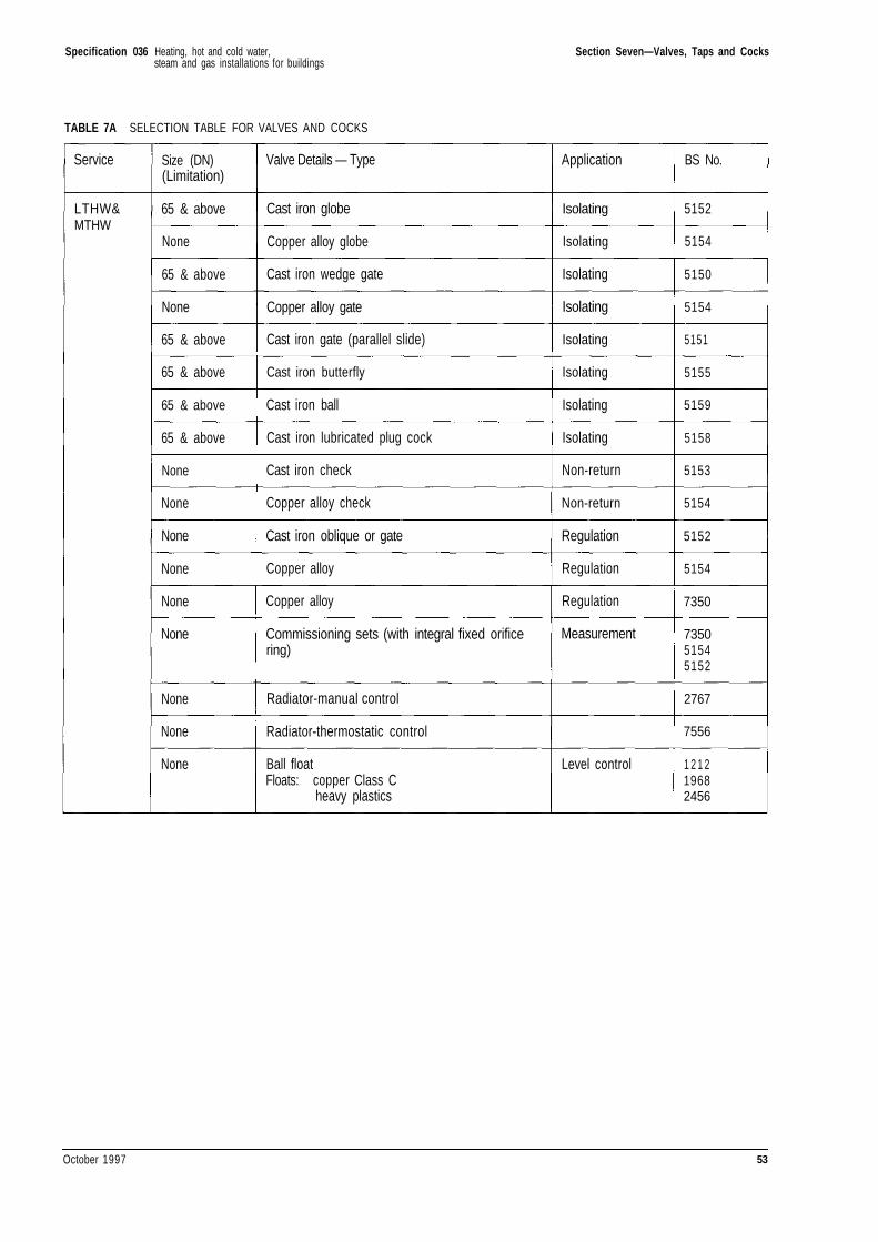
Specification 036 Section Seven—Valves, Taps and Cocks
TABLE 7A SELECTION TABLE FOR VALVES AND COCKS
Service
LTHW&MTHW
Size (DN)(Limitation)
65 & above
None
65 & above
None
65 & above
65 & above
65 & above
65 & above
None
None
None
None
None
None
None
None
None
Valve Details — Type
Cast iron globe
Copper alloy globe
Cast iron wedge gate
Copper alloy gate
Cast iron gate (parallel slide)
Cast iron butterfly
Cast iron ball
Cast iron lubricated plug cock
Cast iron check
Copper alloy check
Cast iron oblique or gate
Copper alloy
Copper alloy
Commissioning sets (with integral fixed orificering)
Radiator-manual control
Radiator-thermostatic control
Ball floatFloats: copper Class C
heavy plastics
Application
Isolating
Isolating
Isolating
Isolating
Isolating
Isolating
Isolating
Isolating
Non-return
Non-return
Regulation
Regulation
Regulation
Measurement
Level control
BS No.
5152
5154
5150
5154
5151
5155
5159
5158
5153
5154
5152
5154
7350
735051545152
2767
7556
1 2 1 219682456
October 1997 53
Heating, hot and cold water,steam and gas installations for buildings
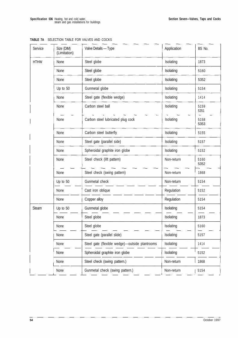
Specification 036 Section Seven—Valves, Taps and Cocks
TABLE 7A SELECTION TABLE FOR VALVES AND COCKS
Service
HTHW
Steam
Size (DIM)(Limitation)
None
None
None
Up to 50
None
None
None
None
None
None
None
None
Up to 50
None
None
Up to 50
None
None
None
None
None
None
None
Valve Details — Type
Steel globe
Steel globe
Steel globe
Gunmetal globe
Steel gate (flexible wedge)
Carbon steel ball
Carbon steel lubricated plug cock
Carbon steel butterfly
Steel gate (parallel side)
Spheroidal graphite iron globe
Steel check (lift pattern)
Steel check (swing pattern)
Gunmetal check
Cast iron oblique
Copper alloy
Gunmetal globe
Steel globe
Steel globe
Steel gate (parallel slide)
Steel gate (flexible wedge) — outside plantrooms
Spheroidal graphite iron globe
Steel check (swing pattern.)
Gunmetal check (swing pattern.)
Application
Isolating
Isolating
Isolating
Isolating
Isolating
Isolating
Isolating
Isolating
Isolating
Isolating
Non-return
Non-return
Non-return
Regulation
Regulation
Isolating
Isolating
Isolating
Isolating
Isolating
Isolating
Non-return
Non-return
BS No.
1873
5160
5352
5154
1 4 1 4
51595351
51585353
5155
5157
5152
51605352
1868
5154
5152
5154
5154
1873
5160
5157
1 4 1 4
5152
1868
5154
54 October 1997
Heating, hot and cold water,steam and gas installations for buildings
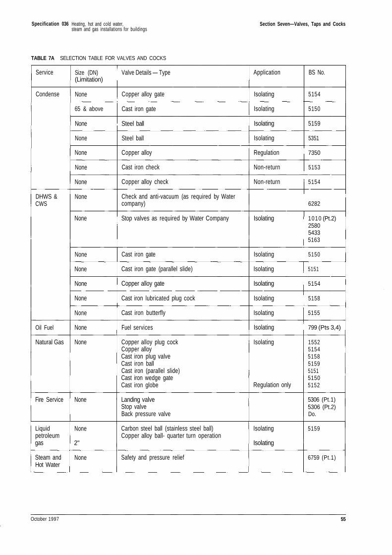
Specification 036 Section Seven—Valves, Taps and Cocks
TABLE 7A SELECTION TABLE FOR VALVES AND COCKS
Service
Condense
DHWS &CWS
Oil Fuel
Natural Gas
Fire Service
Liquidpetroleumgas
Steam andHot Water
Size (DN)(Limitation)
None
65 & above
None
None
None
None
None
None
None
None
None
None
None
None
None
None
None
None
2"
None
Valve Details — Type
Copper alloy gate
Cast iron gate
Steel ball
Steel ball
Copper alloy
Cast iron check
Copper alloy check
Check and anti-vacuum (as required by Watercompany)
Stop valves as required by Water Company
Cast iron gate
Cast iron gate (parallel slide)
Copper alloy gate
Cast iron lubricated plug cock
Cast iron butterfly
Fuel services
Copper alloy plug cockCopper alloyCast iron plug valveCast iron ballCast iron (parallel slide)Cast iron wedge gateCast iron globe
Landing valveStop valveBack pressure valve
Carbon steel ball (stainless steel ball)Copper alloy ball- quarter turn operation
Safety and pressure relief
Application
Isolating
Isolating
Isolating
Isolating
Regulation
Non-return
Non-return
Isolating
Isolating
Isolating
Isolating
Isolating
Isolating
Isolating
Isolating
Regulation only
Isolating
Isolating
BS No.
5154
5150
5159
5351
7350
5153
5154
6282
1010 (Pt.2)258054335163
5150
5151
5154
5158
5155
799 (Pts 3,4)
1552515451585159515151505152
5306 (Pt.1)5306 (Pt.2)Do.
5159
6759 (Pt.1)
October 1997 55
Heating, hot and cold water,steam and gas installations for buildings

Specification 036 Section Seven—Valves, Taps and Cocks
TABLE 7A SELECTION TABLE FOR VALVES AND COCKS
Service
Comp. Air& inert gas
Processfluids
Size (DN)(Limitation)
None
None
Valve Details — Type
Safety and pressure relief
Safety and pressure relief
Application BS No.
6759 (Pt.2)
6759 (Pt.3)
Note: All copper alloy items shall be dezincification resistant
56 October 1997
Heating, hot and cold water,steam and gas installations for buildings
Specification 036
Section Eight—Automatic Controls, Controllers,Cubicles and Panels
8.1 GENERAL
8.1.1 Unless otherwise agreed by the PM theContractor shall arrange for the automatic controlsmanufacturer or specialist to supervise theinstallation, commission all systems, and provide therelated As Installed Drawings.
8.1.2 Control systems shall be provided completewith manuals giving full setting up instructions, faultfinding and locating information. Simple operatingand adjusting instructions shall be recordedpermanently inside the lid or cover of each unit whereappropriate.
8.1.3 Controls shall be electric, electronic,pneumatic or self acting as indicated. The term'motorised' is not meant to imply that only electricalcontrols are acceptable.
8.1.4 Electrical connections between internalcomponents shall be soldered but units and individualitems such as clocks shall preferably be of the plug-intype with contacts of not less than 10 ampere rating.
8.1.5 Controls shall conform with therequirements of the Building Regulations.
8.1.6 The control systems shall be compatible withthe Building Energy Management Systems providedas indicated.
8.2 SPACE HEATING AND DOMESTIC HOT WATERCONTROL
8.2.1 Primary Temperature Control
Control Systems
8.2.1.1 The water flow temperatures in the heatingsystems shall be controlled by the following systems asindicated:
a) On/off control;
b) Modulating control;
c) Weather-compensated control.
On/off Control
8.2.1.2 On/off control shall be achieved by means ofthermostats mounted in the positions indicated,controlling 2 or 3 port motorised control valves,circulating pumps, boiler firing equipment, fans or anyother similar type of plant as indicated.
Modulating Control
8.2.1.3 Modulating control shall be achieved bymeans of temperature detectors mounted in thepositions indicated, controlling two or three portmotorised control valves via a proportional, orproportional plus integral controller as indicated.
Weather-Compensated Control
8.2.1.4 Weather-compensated control shall beachieved by a blending arrangement or by modulatingthe primary flow to a heat exchanger as indicated.
8.2.1.5 These systems shall comprise outside airtemperature detectors fixed in the positions indicatedand operated in conjunction with water temperaturedetectors in the relevant heating flow mains.Controllers shall automatically adjust the flow watertemperatures, as determined by the outsidetemperature, via three port or two port control valvesas indicated. Manual adjustment of the controlschedule shall be provided independently at light andheavy load settings.
8.2.1.6 Provision for control schedule reset frominternal temperature detectors shall be included.
October 1997 57
Heating, hot and cold water,steam and gas installations for buildings
Specification 036 Section Eight—Automatic Controls, Controllers, Cubicles and Panels
8.2.2 Time Programme Control
Control Methods
8.2.2.1 Time control of the heating systems shall beby the following methods as indicated:
a) On/off time-clock control;
b) Optimum Start Control and Optimum OffControl.
8.2.2.2 Daily and weekly programme facilities shallbe adjustable to suit the plant and building response.
8.2.2.3 Facilities shall be provided to allow pumpsto run on after boilers are switched off to allow forheat dissipation. (See Section 2.10.3).
8.2.2.4 Where indicated a programmable facilityshall be provided to allow extensions or reductions toany daily heating period and deletions for holidays.
8.2.2.5 Unless otherwise indicated:
a) Controllers shall be programmable toprovide two independent heating periodsduring any part of a 24 hour period.
b) Clocks shall be driven by synchronousmotors or electronic timers with a selfmaintaining or electrical reserve of not lessthan 72 hours.
c) Clocks shall incorporate facilities foromitting days on a seven day programme.
d) Frost and condensation protection for thebuildings shall be provided and monitoredby external and internal temperaturedetectors respectively during 'heating-offperiods. The external detectors shall controlthe heating pumps and the internaldetectors shall control the heat sources.
On/Off Time Control
8.2.2.6 Where indicated clocks used on weather-compensated circuits shall be provided with additionalcontacts to provide a boost to reduce the buildings pre-heat period. Boost shall be achieved by fully openingthe compensated circuit mixing valve unless otherwiseindicated. Boost termination shall be activated wheninternal temperature reaches set-point.
Optimum Start Control
8.2.2.7 These controllers shall provide optimumstart of heating plant taking into account the thermalcapacity and response of the buildings, and the
external and internal temperatures as appropriate.They shall provide boost during building pre-heatperiods and early start facilities after prolongedshutdown of plant. Boost termination shall beactivated by the internal temperature detectors.
8.2.2.8 Unless otherwise indicated:
a) External temperature detectors shall bemounted on the north sides of buildings atroof level and be shielded from direct solarradiation. The detectors shall be sensitive tonight sky radiation and shall be capable ofmeasuring external air temperatureindependently of wind direction.
b) Internal temperature detectors shall belocated in representative rooms havingthermal performances typical of thebuildings or zones to be controlled or asindicated.
Optimum Start and Optimum Off Control
8.2.2.9 Where indicated optimum start controllersshall be provided with optimum off facilities, whichoverride the day controls when there is sufficientresidual heat for the buildings not to drop below aminimum temperature by the end of the working day.They shall control the heat sources, circulating pumpsand control valves as appropriate.
8.2.2.10 The set point for the minimum temperatureat the end of the working day shall be adjustable.
8.2.3 Space Temperature Control
Control Systems
8.2.3.1 Internal temperature control shall beprovided by one of the following systems as indicated:
a) On/off control;
b) Modulating control;
c) Thermostatic radiator valves;
d) Weather-compensated control with internalcorrection.
On/Off and Modulating Control
8.2.3.2 This shall be achieved by the use of spacethermostats mounted in the positions indicatedcontrolling 2 or 3 port motorised valves as indicated.
58 October 1997
Heating, hot and cold water,steam and gas installations for buildings
Specification 036 Section Eight—Automatic Controls, Controllers, Cubicles and Panels
Weather-Compensated Control with InternalCorrection
8.2.3.3 Weather-compensated control with internalcorrection shall be achieved by the use of spacethermostats mounted in the positions indicatedarranged to modify the weather-compensated controlschedule dependent on internal temperature.
8.2.3.4 Set point internal temperature shall beadjustable. The influence of internal temperaturevariation on the control schedule shall be adjustable.
8.2.4 Room Thermostats and TemperatureDetectors
8.2.4.1 Room thermostats for space heatingtemperature control shall comply with relevant partsof BS EN 60730, 60738 and 61058.
8.2.4.2 Adjustable thermostats shall be providedwhere indicated. A clearly visible indicator andcalibrated numerical scale clearly marked in °C shallbe provided for temperature adjustment without theuse of tools. Covers shall prevent unauthorisedtampering with the temperature settings.
8.2.4.3 Non-adjustable thermostats shall beprovided where indicated. They shall have noexternal means for changing the switchingtemperature.
8.2.4.4 Room thermostats passing a load current ofless than 12 amps through their contacts duringnormal operation shall be fitted with shunt connectedaccelerator heaters across the supply.
8.2.4.5 Where the load current exceeds the rating ofthe thermostat contacts, separate contactors shall beprovided.
8.2.4.6 Room thermostats and temperaturedetectors shall be mounted in a position representativeof the zone or space heated by the emitting system orappliance to be controlled. Items shall not be mountedon external walls, indirect sunlight, draughts or besubject to heating from any other equipment. Wallmounting height shall be 1.5 metres from the floor.
8.2.5 Heating Calorifiers
8.2.5.1 Control of secondary heating systems shallbe as listed in Clause 8.2.3.1.1.
8.2.5.2 Modulating control of heating calorifierswith primary media of MTHW, HTHW or steam shallbe to the dictates of secondary flow temperaturesensors via proportional plus integral controllers, orself-actuated valve systems as indicated.
8.2.5.3 Steam control shall be by means of tightshut-off modulating valves in the steam connections.Sensing elements shall be capable of withstanding thehighest temperatures the systems will attain.
8.2.5.4 Primary hot water control shall be by threeport mixing valves in diverting application positionedin the primary returns. The valves shall be electric,pneumatic or self acting. Electrically operated valvesshall be fitted with a spring return, or other means toclose the valve to service, in the event of a local powerfailure, and automatically return the system to normaloperation on power resumption. Control valves shallbe provided with means of isolation at each port.Sensing elements shall be suitable for the highestsystem temperature.
8.2.5.5 Calorifiers where the maximum secondaryoperating temperature is less than that of the primarysystem shall have high limit temperature controlscomprising automatically operated isolating valvesinstalled in the primary flow connections controlled bylimit thermostats installed in the calorifier bodies orin the secondary flow connections before any valves.The valves shall be arranged to be open under normaloperating conditions. In the event of abnormally highsecondary temperature the control shall close thevalve and lock out, requiring manual reset. In theevent of power failure the valve shall close and reopenautomatically upon restoration of supply—if thecontrol will allow it.
8.2.6 Combined Heating and DHWS System
8.2.6.1 Control of secondary heating systems shall beas detailed in Clause 8.2.3.1.1.
8.2.6.2 DHWS storage calorifiers shall be providedwith on/off type controls with sensors fitted in thecalorifier shells.
8.2.6.3 Storage calorifiers shall be fitted with thelimit controls specified in Clause 8.2.5.5.
8.2.7 DHWS Systems
8.2.7.1 External contact thermostats andtemperature indicators shall not be installed withoutprior approval.
8.2.7.2 The control of single storage vessel DHWSsystems supplied from separate automatically-firedDHWS boiler(s) shall be by means of immersion typethermostats in the storage vessels, wired in serieswith the boiler control thermostat(s) and arranged tostart and stop the boiler(s) at pre-set temperatures.
October 1997 59
Heating, hot and cold water,steam and gas installations for buildings
Specification 036 Section Eight—Automatic Controls, Controllers, Cubicles and Panels
8.2.7.3 In multi-storage vessel DHWS systems eachvessel shall be controlled by a separate temperaturecontrol system.
8.2.7.4 Unless otherwise indicated operatingelements in hot water storage vessels shall be situatedone third up from the bottom of the vessels.
8.2.7.5 Each DHWS calorifier shall be fitted withthe limit controls specified in clause 8.2.5.5.
8.2.7.6 Where indicated clock controls shall beprovided for the primary heat source.
8.3 CONTROLLERS
8.3.1 Types and Construction
8.3.1.1 Controllers shall be of the following types asindicated:
a) On/off;
b) Proportional;
c) Integral;
d) Proportional plus integral.
8.3.1.2 Controllers shall be contained within ametal case to BS EN 60529 : 1992 IP 54, or asindicated, with a lockable cover suitable for wall,frame or panel mounting as indicated.
8.3.1.3 Basic adjustments (such as slopecharacteristics, sensitivity, and anti-huntingadjustments) shall be concealed and tamper-proof, thepanels being lockable. The remaining controlfunctions shall be accessible and protected by meansof lockable and tamper-proof covers.
8.3.2 On/Off Controllers
8.3.2.1 Differentials shall be adjustable over theentire ranges of the controllers.
8.3.2.2 Temperature scales shall be numerical andclearly marked.
8.3.3 Integral Controllers
8.3.3.1 The set points and integral action timesshall be adjustable.
8.3.4 Proportional Plus Integral Controllers
8.3.4.1 The set points, proportional bands andintegral action times shall be adjustable asappropriate.
8.3.4.2 The controllers shall be able to accept signalinputs from either single or numbers of detectorsworking together as indicated.
8.4 CONTROL CUBICLES AND PANELS
8.4.1 Construction
8.4.1.1 As far as is practicable all controls, indicatorlamps and instruments shall be grouped and mountedtogether in a cubicle or on a floor or wall-mountedpanel. Cubicles and panels shall be constructed toMOD (ex PSA) Standard Specification (M&E) No. 159and provide the degree of protection to BS EN60947—1 as indicated. Where busbars, switchgearand fuse-boards are to be included in the controlcubicle or panel the assembly shall comply with BS5486 and BS EN 60439.
8.4.1.2 Cubicles over 1500mm high shall havehinged and lockable access doors with means forinternal release. Other panels shall be provided withhinged and lockable access doors or covers at the frontof the panel and/or back of the panel as required tofacilitate maintenance. Access doors or covers shallincorporate sealing gaskets. Two keys shall beprovided which shall be common to all locks on allpanels.
8.4.1.3 Access doors or covers shall be so arrangedthat access to panels cannot be made until anisolating device, interlocked with each door or cover, isopened and all equipment accessible through that dooror cover isolated. A purpose-made device shall beprovided to enable a competent examiner to overridethe interlock when the door or cover has been opened.
8.4.1.4 Cubicles or panels shall be installed onbuilders work bases or secured direct to the floor.Assemblies secured directly to the floor shallincorporate metal plinths. In all cases fixing holes anddetachable lifting eyes shall be provided.
8.4.1.5 Cubicles shall be supplied painted internallywith a matt white finish, and cubicles and panels shallalso be finished externally with a semi-gloss stoved orcellulose enamel finish of BS 4800 colour OOA05, or asapproved by the PM. Surfaces shall be properlyprepared before final finishing and the externalappearance shall be of a high standard.
8.4.1.6 Indicating lamps, instruments and controlsshall be, as far as is practicable, from the samemanufacturer and of the same style to provideuniformity of appearance and to facilitatemaintenance. Externally visible equipment shall be
60 October 1997
Heating, hot and cold water,steam and gas installations for buildings
Specification 036 Section Eight—Automatic Controls, Controllers, Cubicles and Panels
flush mounted, with minimum projection, and fixedsecurely to the front panels or other members.Internal equipment shall be secured to purpose-maderails or mounting bars. Fixings shall incorporateshake-proof washers or other vibration resistantfastenings.
8.4.1.7 Approximate positions of the control cubiclesare indicated on the Contract drawings. The preciselocation of control cubicles and panels shall be agreedwith the PM on site.
8.4.1.8 Items on the outside faces of cubicles andpanels shall be clearly identified by white/black/whitelaminated engraving plastic labels.
8.4.1.9 Control cubicles and panels shall, as far asis practicable, be manufactured, equipped, wired andtested before delivery to site.
8.4.2 Indicator Lamps
8.4.2.1 Tungsten filament indicator lamp lenscolours and colour significance shall comply with BSEN 60073 : 1993 and lenses shall be not less than25mm in diameter. Indicator lamp transformers shallbe of the double wound type and comply with therelevant requirements of BS 3535. Indicator lampsshall be of the following types as indicated:
a) Red neon glow lamps with a rating of 0-
b) Tungsten filament extra low voltage lampswith a voltage rating 10% higher than theirnormal supply voltage.
c) Tungsten double filament low voltage lampsof the special service switchboard type with200/260V nominal voltage and a rating of12W.
d) Light emitting diodes.
8.4.2.2 Where indicator lamps are not immediatelyadjacent to their corresponding controller, theirfunction shall be clearly labelled.
8.4.3 Wiring
8.4.3.1 Internal wiring shall be colour coded to BS6346 and in general shall be bunched and run ontrays or in purpose-made slotted plastic cabletrunking. Positive fixing of cable ends shall beensured by purpose-made clamps, pinch-typeterminals, crimped cable tags or other approvedtermination devices. Cable ends shall be permanentlyidentified.
8.4.3.2 Grouped terminal blocks of adequatecapacity with permanent labels shall be provided forall wires leading to equipment outside the cubicles orpanels. Removable covers or other facilities shall beprovided for the entry of incoming cables, conduits,trunking, etc. with means for effective earthing to thecubicles or panel chassis. Non-ferrous earth terminalstuds of diameter not less than M6 shall be providedon each panel and cubicle.
8.4.3.3 Where mains power termination occurs at orwithin control cubicles or panels and the currentratings exceed 100 amperes, soldered socket, crimpedor bolted terminals of adequate size shall be provided.
8.4.3.4 The control circuitry within cubicles andpanels shall be arranged such that each controlsystem is separately protected. For the purposes ofthis clause a control system shall be defined as thatnecessary to sustain an item of plant and/or control ofa zone. Standby plant shall have separately fusedsupplies. Fuses, terminal blocks and all items ofequipment shall be readily identified by means ofclearly visible labels secured to them by screws orother methods approved by the PM.
October 1997 61
Heating, hot and cold water,steam and gas installations for buildings
Specification 036
Section Nine—Miscellaneous Equipment
9.1 THERMOMETERS
9.1.1 General
9.1.1.1 Dial type thermometers shall be of the vapourpressure type. Liquid in glass thermometers shallcomply with the requirements of BS 1704 or BS 1041, asappropriate. Where requested by the PM, the Contractorshall demonstrate the accuracy of the thermometers tothe requirements of these British Standards.
9.1.1.2 A thermometer shall be fitted on eachheating return at its point of connection to the mainreturn header or pipe. Where returns are broughtback separately to the boiler a thermometer shall befitted on each return connection.
9.1.1.3 Thermometers shall be positioned so thatthe tails are truly subject to the temperature of thewater to be measured.
9.1.1.4 Direct (local) mounting thermometers shallhave rigid stems either vertical, right angle, orhorizontal pattern.
9.1.1.5 Right-angle or horizontal thermometersshall be provided for fitting to vertical pipes or verticalfaces of cylinders, etc.
9.1.1.6 Thermometers fitted more than 2m abovethe floor shall be of the dial type.
9.1.1.7 Thermometer pockets shall comply generallywith the requirements of BS 2765 and be inserted,and so positioned in the waterways, that they offerminimum resistance to water flow. Pockets shall be ofsteel except for copper installations where they shallbe of brass. Pockets shall be filled with an approvedheat-conducting medium.
9.1.2 LTHW Heating and DHWS Systems
9.1.2.1 Liquid in glass thermometers shall be of thewide-bore lens-magnifying type, enclosed in robustcases. Scales shall be boldly marked and graduated tocover the range 0°C to 120°C.
9.1.2.2 Dial type thermometers shall be as specifiedin Clauses 9.1.3 but with scales graduated to cover therange 0°C to 120°C.
9.1.3 MTHW and HTHW Heating Systems
9.1.3.1 Dial type thermometers shall be used. Theyshall be approved metal or moulded plastics casedinstruments. They shall be complete with mild steelor stainless steel pressure proof, screwed, separablepockets. Metal cases shall be finished in enamel, withchromium plated bezels.
9.1.3.2 Dials shall be white, not less than 100mmdiameter, with black figured scales graduated to coverthe range 0°C to 150°C for MTHW systems and tocover the range 0°C to 200°C for HTHW systems.
9.1.3.3 Dial thermometers for remote reading shallbe provided with the necessary length of capillary tubeencased in a non-corrodible sheath giving protectionfrom mechanical damage. Connecting tubes shall beneatly clipped to walls, etc, with purpose-made clipsspaced at not more than 300mm intervals.Thermometers that are to be wall-mounted shall bescrewed to the wall.
9.2 PRESSURE GAUGES
9.2.1 Pressure gauges shall comply with BS 1780with Class I industrial scales. Where requested by thePM, the Contractor shall demonstrate the accuracy ofthe gauges to the requirements of the BS.
9.2.2 Pressure gauges fitted to plant or pipeworkassociated with steam, LTHW, MTHW and HTHWsystems shall have dials calibrated in bar from zero tonot less than 1.3 times and not more than twice theoperating pressure. Where fitted on pressure vesselsand boilers, the gauges shall be as required by BS759: Part 1 with dials not less than 150mm diameterand with cases of enamelled steel. Where fittedelsewhere, the dials of gauges shall be not less than100mm diameter and the cases shall be of enamelled
62 October 1997
Heating, hot and cold water,steam and gas installations for buildings
Specification 036 Section Nine—Miscellaneous Equipment
steel or moulded plastics. Pressure gauges shall befitted with lever handle cocks and, where appropriate,syphon pipes. Pressure gauges shall be of matchingfinish to dial type thermometers.
9.2.3 Pressure gauges used solely to indicate thealtitude or head and pressure of water shall have dialscalibrated in bar and metres head. Other gauges shallbe calibrated in bar and/or kPa to suit the application.In addition to the indicating black pointer, gaugesshall be provided with an adjustable tamper-proof redpointer set to indicate the normal working pressure orhead of the system.
9.3 STEAM TRAPS
9.3.1 Steam traps shall be approved and of thefollowing types as indicated:
a) Float with thermostatic air vent,
b) Inverted bucket,
c) Thermostatic balanced pressure,
d) Bimetallic thermostatic,
e) Thermodynamic.
9.3.2 Thermostatic balanced pressure, andbimetallic thermostatic traps shall be preceded by anunlagged cooling leg of length sufficient to preventwaterlogging.
9.3.3 Traps shall be capable of shutting againstmaximum steam pressure.
9.3.4 Except where integral units are provided astrainer shall be fitted on the inlet side of each trap.Where the condensate is raised to a higher level, acheck valve shall be fitted on the outlet side of eachtrap, except on inverted bucket traps where the checkvalve shall be fitted on the inlet side. An isolatingvalve shall be fitted before each strainer and also inthe condensate pipework on the outlet from each trap.Unions shall be installed on each side of the completetrap assembly for ease of removal. Mechanical trapsshall have renewable valves and seats and shall beprovided with automatic air venting valves.
9.3.5 Facilities for detecting steam leakagethrough traps shall be provided by one of the followingmethods as indicated:
a) Sensor chambers fitted immediatelyupstream of traps to be used in conjunctionwith battery powered indicators.
b) As a) but with remote indicator board.
9.4 STRAINERS FOR HOT WATER HEATINGSYSTEMS
9.4.1 Strainers shall be provided to protectmeters, control valves and other sensitive fittings orcircuits as indicated.
9.4.2 Strainer bodies for line sizes up to DN50shall be of bronze to BS 1400, PB1, and otherwise ofcast-iron to BS 1452, Class 180. Strainer pressureratings shall be at least 150% of maximum servicepressure in the application.
9.4.3 Strainer screens shall be of a suitablestainless steel with perforation free-area at least 250%of line cross-sectional area. The diameter of theperforations shall be in the ranges 0.7-0.9mm and 1.5-1.8mm, for sizes up to DN50 and larger sizesrespectively.
9.4.4 Strainers shall be installed in parallel toenable on-line maintenance at the locations asindicated.
9.5 HOT AND COLD WATER MIXING VALVES ANDFITTINGS
9.5.1 Thermostatically operated mixing valvesshall be of gunmetal or brass construction withchromium-plated finish. Each mixing valve shall beequipped with a backplate for wall fixing. Alternativebodies in thermoplastic material will be considered.Each mixing valve shall have a control thermostatcapable of providing a constant mixed watertemperature under the available hot and cold waterpressures and of closing down the hot water inletwithin 5 seconds in the event of the cold water failing.The capacity of each individual shower mixing valveshall be a minimum of 4.5 litre/min. Each mixingvalve shall be provided with a temperature regulatinghandle or knob permitting regulation of the mixedwater temperature up to a maximum of 45°C.
Means shall be provided for varying the maximumsettings and these shall be tamperproof. The valvesshall also have provision for controlling the maximumrate of outlet flow.
9.5.2 Thermostatically operated mixing valvesserving groups of showers shall be capable ofproviding a minimum of 4.5 litre/min simultaneouslyto each shower and be provided with means of lockingthe regulating handle to prevent unauthorisedinterference. The water inlets shall be provided withchromium-plated non-return valves. The construction,finish and thermostatic control regulation of themixing valve shall be as specified in Clause 9.5.1.
October 1997 63
Heating, hot and cold water,steam and gas installations for buildings
Specification 036 Section Nine—Miscellaneous Equipment
9.5.3 An isolating valve and strainer shall beprovided on the hot and on the cold supply to eachmixing valve.
9.5.4 Each shower shall be provided with anisolating valve on the riser pipe of type as indicated.
9.5.5 Manually operated mixing valves whereindicated shall incorporate anti-scald devices and besuitable for the working conditions.
9.5.6 Unless otherwise indicated showers shall bestainless, robust and vandal resistant installationswith fixed spray nozzle terminals.
9.6 GAS METERS
9.6.1 Unless otherwise indicated primary meterswill be supplied and fixed under separatearrangements. The Contractor shall connect to theoutlet sides of these meters.
9.6.2 Secondary meters, where indicated, shall besupplied and fixed in the positions shown and shall becapable of the duties indicated.
9.6.3 Pressure testing nipples shall be fitted atthe outlets of gas meters. A strainer, complying withthe meter manufacturer's recommendations, shall beinstalled on the inlet side of each secondary meter.
9.7 PLATFORMS, GALLERIES, STAIRWAYS ANDLADDERS
9.7.1 General
9.7.1.1 Platforms, gantries, galleries, stairways,accessways and ladders shall be provided as indicatedto BS 5395 Part 3 and be guarded on all sides withhand-rail systems in accordance with Regulations.
9.7.1.2 Structures shall be fabricated of steel andprotectively painted as indicated.
9.7.1.3 Ladders shall comply with BS 4211.
9.7.2 Flooring, Landings and Stair-Treads
9.7.2.1 Flooring and stair-treads shall comply withBS 4592 and the following requirements.
9.7.2.2 Unless otherwise indicated the design loadsshall be as stated in BS 4592.
9.7.2.3 The minimum depth of load bearing barsshall be 30mm.
9.7.2.4 Fixing clips shall be provided.
9.7.2.5 Toe plates shall extend at least 100mmabove floor level and be fixed down only around cut-outs.
9.7.2.6 The protective finish shall be galvanised toBS 729, etch primed, and dipped in bituminous paintto BS 3416.
9.7.3 Hand-Rail System
9.7.3.1 Hand-rails shall be made using aproprietary system designed to accommodate loads asindicated with a horizontal deflection at half designload not exceeding 0.8% of the pitch betweenstandards, or 25mm whichever is less.
9.7.3.2 Top hand-rails shall be 1100mm above floorlevel when horizontal and 900mm above stair pitchlines. Intermediate rails shall be provided at mid-height.
9.7.3.3 Rails and ball-standards shall be 32mmnominal bore medium class tube to BS 6323 (Parts 1to 8).
9.7.3.4 Where rails do not terminate on thestructure the finish shall be with return bends.Terminations to the structure shall be made withpurpose-made flanges.
9.7.3.5 Ball standards shall be pitched at distancesnot exceeding 1800mm. Each ball shall have grub-screws for clamping the rails.
9.7.3.6 Toe plates shall be 100mm x 6mm sectionsteel plates spliced together and secured to the ballstandards.
9.7.3.7 Ball standards, hand-rails, toe plates,connectors and all fixtures and fittings shall begalvanised after manufacture to BS 729.
9.7.3.8 Joints in hand-rails shall be made usingscrewed plugs or nipples or internal split dowels.Joints shall be kept clear of standards by at least 20%of the relevant pitch. Joints shall be smooth.
9.7.4 Stairways
9.7.4.1 A common pitch angle not exceeding 42°shall be adopted for the stairways at each location.
9.7.4.2 Flights of stairs shall not exceed 16 risers,and shall not exceed 3.36m or 3.15m in height withpitch angles of 42° and 38° respectively.
9.7.4.3 Where a stairway exceeds 16 risers eachflight shall be equal and separated by a landing.
64 October 1997
Heating, hot and cold water,steam and gas installations for buildings
Specification 036
Section Ten—Thermal Insulation
10.1 GENERAL
10.1.1 Thermal insulation and methods ofapplication shall comply with the requirements of BS5422 and BS 5970. Insulating materials that containand/or require the use of CFC's in their manufacture,shall not be used.
10.1.2 Thermal insulation materials, adhesives andfinishes, shall be suitable in all respects for continuoususe without degradation throughout the range ofoperating temperatures and within the environmentindicated. They shall be designed to provide proofagainst rotting, mould, fungal growth, attack byvermin and birds.
10.1.3 Insulating materials for external application(Clause 10.2.2) shall be approved. The materials shallbe such that if subjected to repeated wetting theyshall:
a) Retain adequate strength;
b) Not permanently deteriorate in terms ofstrength and thermal resistance;
c) Continue to be chemically inert to adjacentmetalwork.
10.1.4 Unless otherwise indicated as non-combustible, any thermal insulation used incirculation spaces, fire escape routes, ceiling voids orservice ducts shall be inherently Class O (ie notachievable by a treatment or covering) as defined byApproved Documents B2/3/4 (1992 Edition) of TheBuilding Regulations 1991 (or the equivalent inScotland). Insulating materials conforming to Class 1of BS 476: Part 7 may be used, where indicated, inother areas of buildings.
10.1.5 Any adhesive or surface finish treatmentshall not degrade the fire qualities of the insulationmaterial. When requested by the PM, evidence of fireclassification obtained from an approved testinglaboratory shall be provided by the Contractor.
10.1.6 Where any work is carried out on existingthermal insulation material or finish which containsasbestos in any form, the Contractor's attention isdrawn to his responsibilities in accordance with theapproved Code of Practice and Guidance Note 'Workwith asbestos insulation and asbestos coatings'published by the Health and Safety Executive; 'TheAsbestos Regulations' and 'The EnvironmentalProtection Act 1990: Part 1, Special Waste Regulations1996'.
10.1.7 The minimum thickness of insulation for allhot fluids and cold water distribution services shall beto BS 5422 : 1990, Tables 7 to 15 inclusive, reproducedin this Specification. Where the indicated thickness inthese tables is not a commercial size, the nearestlarger commercially available thickness of insulationshall be provided. The thickness of insulation inTables 7 to 15 shall be increased by one standard size,or as indicated, for pipework in external service ductsand pipework external to buildings.
10.1.8 Insulation for protection from condensationshall be provided as indicated.
10.1.9 The thickness of insulation applied tovessels and tanks shall be as indicated in Tables 7 to15 for flat surfaces.
10.2 TYPES OF INSULANT
10.2.1 Within Buildings
10.2.1.1 Thermal insulation shall be as describedbelow:
a) Boilers, calorifiers, cylinders, boiler feedtanks, steam and condensate receivers(except where insulated jackets areprovided) shall be—preformed rigid sectionsor slabs.
b) All pipework, flanges and valves carryingfluids at temperatures above 50°C and otherpipework as indicated shall be pre-formedrigid sections and/or an approved pre-
October 1997 65
Heating, hot and cold water,steam and gas installations for buildings
Specification 036 Section Ten—Thermal Insulation
insulated pipework system as indicated.Valves and flanges shall be insulated inaccordance with clause 10.3.4.
c) Flues from oil and solid-fuel fired boilers, gasboilers fired by forced air burners and fluesservicing all multi-boiler installations, exceptdiluted flue systems, or where the flue is ofpre-insulated or twin wall design shall bepreformed rigid sections or slabs, applieddirect to the flue and finished withaluminium, or other suitable metallic casingapproved by the PM.
d) Heating feed and expansion cisterns andvent pipework shall be insulated asindicated.
e) Unless otherwise indicated, cold waterstorage tanks, DHWS cold feeds and openvents, incoming mains water services and allCWS distribution pipework shall beinsulated. Type of insulation to be asindicated.
10.2.1.2 The operational surface temperature ofcladding applied to boilers, other vessels, pipeworkand flues shall not exceed 55°C in an ambienttemperature of 20°C.
10.2.1.3 With the exception of DHWS and CWSincoming main and distribution systems, pipeworkinstalled in occupied areas in the followingcircumstances shall be uninsulated unless otherwiseindicated:
a) Pipework whose surface temperature isbetween 50°C and 95°C and located up to2m above floor level;
b) Pipework located at less than 2m above floorlevel which is specifically designated asheating surface and whose surfacetemperature exceeds 95°C but which isscreened against physical contact;
c) Pipework located at more than 2m abovefloor level which is specifically designated asheating surface.
10.2.2 External to Buildings
10.2.2.1 Preformed insulation shall be appliedto:
a) Insulation to steam condensate and hot waterdistributing mains above ground and inducts, chases and trenches, including all
valve bodies and flanges shall be preformedrigid or flexible sections protected andfinished as specified in sub-section 10.4.4.
b) Insulation to cold water pipework run aboveground external to buildings and run inducts, chases, roof spaces shall be preformedrigid or flexible sections.
c) Expansion devices shall be insulated asindicated.
10.3 METHODS OF APPLICATION
10.3.1 The insulation shall fit closely to thepipework and other surfaces without gaps betweenjoints.
10.3.2 Each section of preformed insulation shallbe secured to the pipe by one of the following means:
a) Circumferential tie-wires, each formed fromone turn of galvanised wire not less than1.5mm thick, spaced not more than 450mmapart.
b) Circumferential bands, spaced not morethan 450mm apart, of galvanised or non-ferrous metal (not less than 20mm wide and0.5mm thick), plastic fabric (no less than50mm wide) or adhesive tape.
c) In the case of preformed flexible insulationthe manufacturer's recommended method ofattachment shall be used.
10.3.3 Rigid insulation applied to boilers, calorifiers,cylinders, hotwells, steam and condensate receivers shallbe secured with non-ferrous metal or plastic fixings.
10.3.4 Valve bodies and flanges on insulatedpipework in buildings shall be insulated with flexibleinsulation, encased in aluminium boxes, or otherdevices approved by the PM. The enclosures shall bearranged for easy removal. The glands on valvespindles shall project beyond the insulation.
10.3.5 Insulation shall be continuous throughsupports, where the material used shall be capable ofsupporting the imposed load. Where pipe movementis facilitated by rollers or similar devices, the loadbearing insulation shall extend beyond the limits ofpipe movement. The Contractor shall ensure thatwhere appropriate the requirements of Clause 10.4.1.1are satisfied.
66 October 1997
Heating, hot and cold water,steam and gas installations for buildings
Specification 036 Section Ten—Thermal Insulation
10.4 FINISHES
10.4.1 General
10.4.1.1 The preformed insulation outside surfacesshall be smooth, unbroken, uniform and firm. Outercoverings shall be continuous through support joints.
10.4.1.2 Where insulating materials are finishedwith metallic cladding, the cladding shall be bonded toBS 7671 and BS 7430.
10.4.2 In Boiler Houses and Plant Rooms
10.4.2.1 Insulation on vessels shall be protected andfinished by fabricated polished or hammeredaluminium or galvanised steel as indicated.
10.4.2.2 Insulation on pipework shall be protected andfinished by fabricated polished or hammered aluminiumor galvanised steel or rigid plastic as indicated.
10.4.2.3 Fabricated aluminium casings thicknessshall be not less than 1mm on vessels and flue pipingor ducting, not less than 0.7mm on pipework up to150mm outside diameter measured over theinsulation, not less than 0.9mm on pipework 150mmto 450mm outside diameter measured over theinsulation and 1.2mm on pipework over 450mmoutside diameter measured over the insulation.Overlap for aluminium and galvanised steel casings atlongitudinal and circumferential joints shall be notless than 40mm. Heat bridges between the hotsurfaces and the metal casings are not acceptable.
10.4.2.4 Rigid plastic casing shall be made frompurpose-designed sheeting not less than 0.35mm thick.Longitudinal and circumferential joints shall beoverlapped by 40mm. Longitudinal overlaps shall beneatly secured at 150mm centres with plastic rivetsor, with the approval of the PM, with matching selfadhesive tape. Circumferential overlap shall allow forexpansion and contraction. Bends and tees shall befinished with preformed fittings, unless otherwiseindicated.
10.4.3 In Buildings Other Than Boiler Houses AndPlant Rooms
10.4.3.1 For concealed pipework the finishes shall beas follows:
a) In roof spaces, foil faced finishing materials,factory applied to preformed sections andsecured on site with adhesive, sealing tapeand bands where suitable. Alternatively thefinish may be site applied to the satisfactionof the PM. The finish shall be left unpainted.
b) Within sealed parts of the buildingstructure, glass cloth facings applied to theinsulation and secured on site with adhesiveand bands, or finishing material as Clause10.4.3.1(a), or approved preinsulated andclad as indicated. The finish shall be leftunpainted.
c) In all accessible ducts, voids, chases, falseceilings etc, finishing material shall be asClause 10.4.3.Kb), with fabricatedaluminium or galvanised steel or plasticcasings applied to the insulation at accesspoints which could be subjected tomechanical damage, or approvedpreinsulated and clad pipework systems asindicated.
10.4.3.2 For visible pipework the finishes shall be inaccordance with the following as indicated:
a) Cotton canvas not less than 100g/m2 to BS3958: Part 4, Table 2, factory applied topreformed sections, lapped and sealed on sitewith adhesive, and additionally secured withbands and painted;
b) Rigid plastics sheet applied in the factory, or onsite as Clause 10.4.2.4;
c) White lacquered aluminium foil/kraft paperlaminate, factory applied to preformed pipeinsulation, overlaps to be sealed withadhesive and circumferential joints to besealed with 100mm wide matching tape.
10.4.4 External to Buildings In Open Air Or In Ducts
10.4.4.1 The outer covering to the insulation shall bea weatherproof finish which passes continuouslywithout being punctured through pipework supportsand over flanges, expansion joints and anchor points.
10.4.4.2 The weatherproof finish to the insulation ofpipework carrying fluids at temperatures aboveambient shall be one of the following as indicated:
a) Waterproof vapour permeable plastic coatingsystems, brush or spray applied andreinforced with canvas or glass fibre cloth;
b) Roofing felt, sealed with adhesive withoverlaps of at least 50mm, wrapped with25mm mesh by 1mm thick galvanised wirenetting, laced with 1mm thick galvanisedwire and painted two coats of bituminouspaint to BS 3416 Type 1 Class A;
October 1997 67
Heating, hot and cold water,steam and gas installations for buildings
Specification 036 Section Ten—Thermal Insulation
c) Bitumen impregnated fabric systems sealedby the application of heat or by cold welding;
d) Other proprietary weatherproof finishes ofthe type as indicated;
e) Preinsulated pipework systems, of the typeindicated;
f) Polyisobutylene sheets not less than 0.8mmthickness and of tensile strength 3.4 MPa,lapped and sealed by solvent or cold welding.
The finishes specified in Clause 10.4.4.2(b) and (c) shallbe perforated on the under side of all horizontal runswith 6mm diameter holes at approximately 150mmcentres. The horizontally lapped joints shall lie to oneside of the bottom centre line exposed edge downwards,so that the perforations are made in one thickness ofthe material, with the underlying preformed insulationopen to atmosphere at these points.
10.4.4.3 The weatherproof finish to the insulation ofcold water pipework shall be as Clause 10.4.4.2(b), (c),(d), (e) or (f).
10.4.5 PAINTING
10.4.5.1 Insulation shall be painted two coats goodquality heat-resistant paint of approved colour as
indicated, except where concealed, protected by metalor plastics casings, or has weatherproof or specialdecorative/protective finishes. Absorbent surfacesshall have a first coat of primer paint.
10.4.5.2 The paint system shall not adversely affectthe required fire resisting properties to BS 476: Part7—Class 1.
10.4.6 Colour Code
10.4.6.1 Pipework whether insulated, insulated andcased or uninsulated shall be identified with purpose-made self-adhesive colour banding with colours to BS1710. Direction of flow shall also be indicated. Thelocations of identifying bands shall be as indicated.
TABLES OF THERMAL INSULATION THICKNESS
(Based on BS 5422 : 1990—Method of specifyingThermal insulating materials on pipes, ductwork andequipment (in the temperature range — 40°C to+700°C).
Extracts based on BS 5422 : 1990 are reproduced withthe permission of BSI. Complete copies can beobtained by post from BSI Customer Services, 389Chiswick High Road, London, W4 4AL; Tel 0181-996-7000.
68 October 1997
Heating, hot and cold water,steam and gas installations for buildings
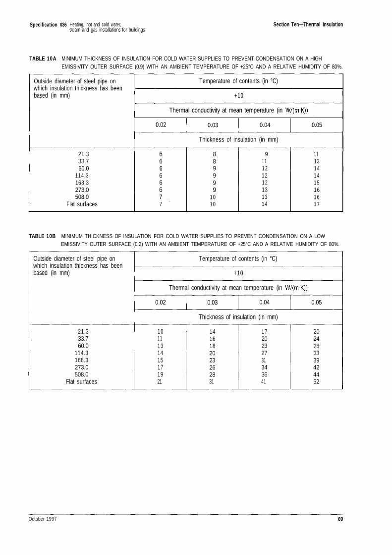
Specification 036 Section Ten—Thermal Insulation
TABLE 10A MINIMUM THICKNESS OF INSULATION FOR COLD WATER SUPPLIES TO PREVENT CONDENSATION ON A HIGHEMISSIVITY OUTER SURFACE (0.9) WITH AN AMBIENT TEMPERATURE OF +25°C AND A RELATIVE HUMIDITY OF 80%.
Outside diameter of steel pipe onwhich insulation thickness has beenbased (in mm)
21.333.760.0
114 .3168.3273.0508.0
Flat surfaces
Temperature of contents (in °C)
+10
Thermal conductivity at mean temperature (in
0.02 0.03 0.04 0.05
Thickness of insulation (in mm)
66666677
889999
1010
91 11 21 21 2131314
1 113141415161 617
TABLE 10B MINIMUM THICKNESS OF INSULATION FOR COLD WATER SUPPLIES TO PREVENT CONDENSATION ON A LOWEMISSIVITY OUTER SURFACE (0.2) WITH AN AMBIENT TEMPERATURE OF +25°C AND A RELATIVE HUMIDITY OF 80%.
Outside diameter of steel pipe onwhich insulation thickness has beenbased (in mm)
21.333.760.0
114.3168.3273.0508.0
Flat surfaces
Temperature of contents (in °C)
+10
Thermal conductivity at mean temperature (in
0.02 0.03 0.04 0.05
Thickness of insulation (in mm)
101 1131415171921
1416182023262831
1720232731343641
2024283339424452
October 1997 69
Heating, hot and cold water,steam and gas installations for buildings
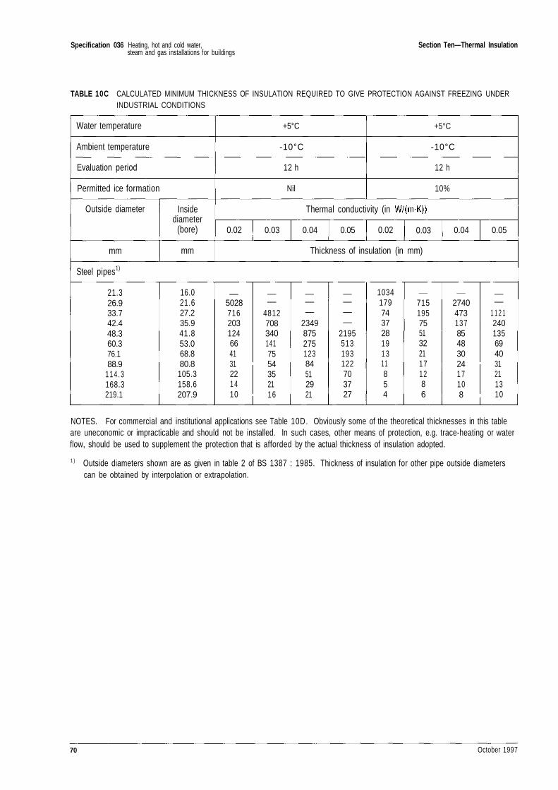
Specification 036 Section Ten—Thermal Insulation
TABLE 10C CALCULATED MINIMUM THICKNESS OF INSULATION REQUIRED TO GIVE PROTECTION AGAINST FREEZING UNDERINDUSTRIAL CONDITIONS
Water temperature
Ambient temperature
Evaluation period
Permitted ice formation
Outside diameter
mm
Insidediameter
(bore)
mm
+5°C
-10°C
12 h
Nil
+5°C
-10°C
12 h
10%
Thermal conductivity (in
0.02 0.03 0.04 0.05 0.02 0.03 0.04 0.05
Thickness of insulation (in mm)
Steel pipes1)
21.326.933.742.448.360.376.188.9
1 1 4 . 3168.3219.1
16.021.627.235.941.853.068.880.8
105.3158.6207.9
_5028716203124664131221410
_—
48127083401417554352116
_——
234987527512384512921
_———
2195513193122703727
1034179743728191311854
__
71519575513221171286
__
27404731378548302417108
_—
1 1 2 1240135694031211310
NOTES. For commercial and institutional applications see Table 10D. Obviously some of the theoretical thicknesses in this tableare uneconomic or impracticable and should not be installed. In such cases, other means of protection, e.g. trace-heating or waterflow, should be used to supplement the protection that is afforded by the actual thickness of insulation adopted.
1 ) Outside diameters shown are as given in table 2 of BS 1387 : 1985. Thickness of insulation for other pipe outside diameterscan be obtained by interpolation or extrapolation.
70 October 1997
Heating, hot and cold water,steam and gas installations for buildings
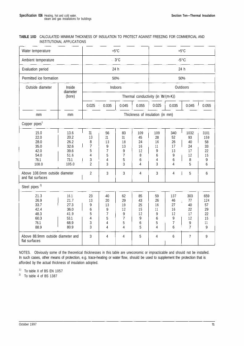
Specification 036 Section Ten—Thermal Insulation
TABLE 10D CALCULATED MINIMUM THICKNESS OF INSULATION TO PROTECT AGAINST FREEZING FOR COMMERCIAL ANDINSTITUTIONAL APPLICATIONS
Water temperature
Ambient temperature
Evaluation period
Permitted ice formation
Outside diameter
mm
Insidediameter
(bore)
mm
+5°C
24 h
50%
Indoors
+5°C
-5°C
24 h
50%
Outdoors
Thermal conductivity (in
0.025 0.035 0.045 0.055 0.025 0.035 0.045 0.055
Thickness of insulation (in mm)
Copper pipes1
15.022.028.035.042.054.076.1
108.0
13.620.226.232.639.651.673.1
105.0
Above 108.0mm outside diameterand flat surfaces
3113875432
2
56211397543
3
833118139753
3
10945241612864
4
10928161 19643
3
34052261713964
4
1032934024171 285
5
31011595833221596
6
Steel pipes 2)
21.326.933.742.448.360.376.188.9
16.121.727.336.041.953.168.980.9
Above 88.9mm outside diameter andflat surfaces
2313965433
3
40201397544
4
6229191 29754
4
854325151 2965
5
5926161 19654
4
1374627161 2976
6
303774022171297
7
659124572922151 19
9
NOTES. Obviously some of the theoretical thicknesses in this table are uneconomic or impracticable and should not be installed.In such cases, other means of protection, e.g. trace-heating or water flow, should be used to supplement the protection that isafforded by the actual thickness of insulation adopted.
1 ) To table X of BS EN 10572) To table 4 of BS 1387
October 1997 71
Heating, hot and cold water,steam and gas installations for buildings
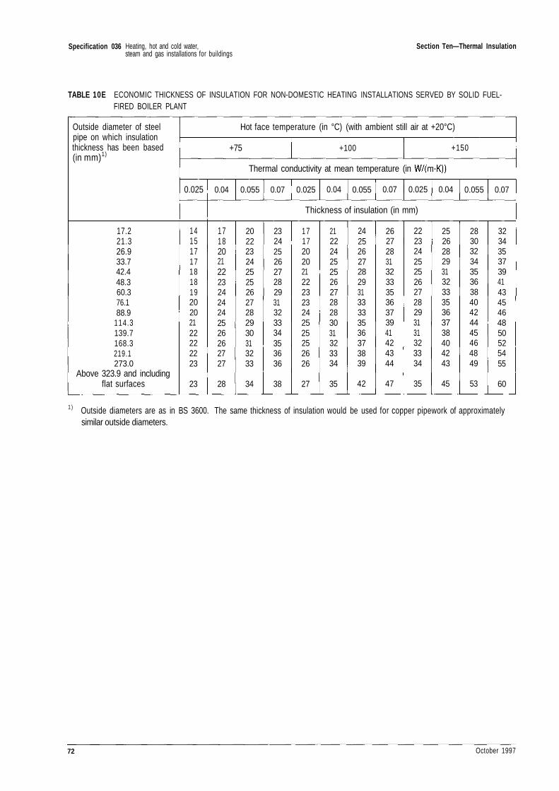
Specification 036 Section Ten—Thermal Insulation
TABLE 10E ECONOMIC THICKNESS OF INSULATION FOR NON-DOMESTIC HEATING INSTALLATIONS SERVED BY SOLID FUEL-FIRED BOILER PLANT
Outside diameter of steelpipe on which insulationthickness has been based(in mm)1)
17.221.326.933.742.448.360.376.188.9
114.3139.7168.3219.1273.0
Above 323.9 and includingflat surfaces
Hot face temperature (in °C) (with ambient still air at +20°C)
+75 +100 +150
Thermal conductivity at mean temperature (in
0.025
1415171718181920202122222223
23
0.04 0.055 0.07 0.025 0.04 0.055 0.07 0.025 0.04 0.055 0.07
Thickness of insulation (in mm)
1718202122232424242526262727
28
2022232425252627282930313233
34
2324252627282931323334353636
38
1717202021222323242525252626
27
2122242525262728283031323334
35
2425262728293133333536373839
42
2627283132333536373941424344
47
2223242525262728293131323334
35
2526282931323335363738404243
45
2830323435363840424445464849
53
3234353739414345464850525455
60
1 ) Outside diameters are as in BS 3600. The same thickness of insulation would be used for copper pipework of approximatelysimilar outside diameters.
72 October 1997
Heating, hot and cold water,steam and gas installations for buildings
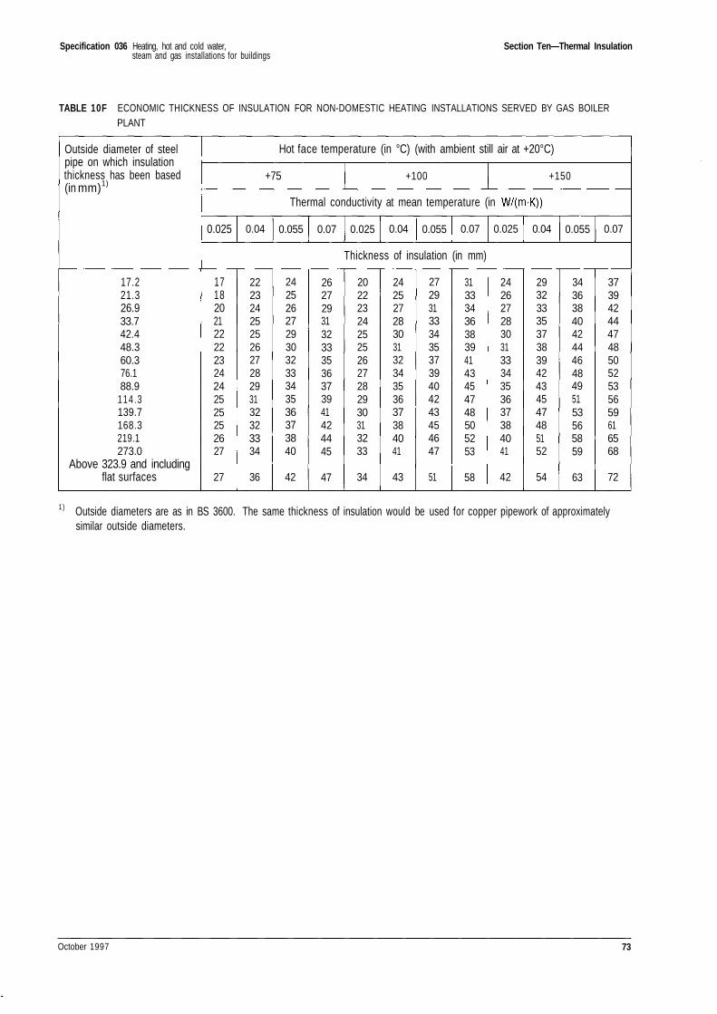
Specification 036 Section Ten—Thermal Insulation
TABLE 10F ECONOMIC THICKNESS OF INSULATION FOR NON-DOMESTIC HEATING INSTALLATIONS SERVED BY GAS BOILERPLANT
Outside diameter of steelpipe on which insulationthickness has been based(in mm)1)
17.221.326.933.742.448.360.376.188.9
114 .3139.7168.3219.1273.0
Above 323.9 and includingflat surfaces
Hot face temperature (in °C) (with ambient still air at +20°C)
+75 +100 +150
Thermal conductivity at mean temperature (in
0.025 0.04 0.055 0.07 0.025 0.04 0.055 0.07 0.025 0.04 0.055 0.07
Thickness of insulation (in mm)
1718202122222324242525252627
27
2223242525262728293132323334
36
2425262729303233343536373840
42
2627293132333536373941424445
47
2022232425252627282930313233
34
2425272830313234353637384041
43
2729313334353739404243454647
51
3133343638394143454748505253
58
2426272830313334353637384041
42
2932333537383942434547485152
54
3436384042444648495153565859
63
3739424447485052535659616568
72
1) Outside diameters are as in BS 3600. The same thickness of insulation would be used for copper pipework of approximatelysimilar outside diameters.
October 1997 73
Heating, hot and cold water,steam and gas installations for buildings
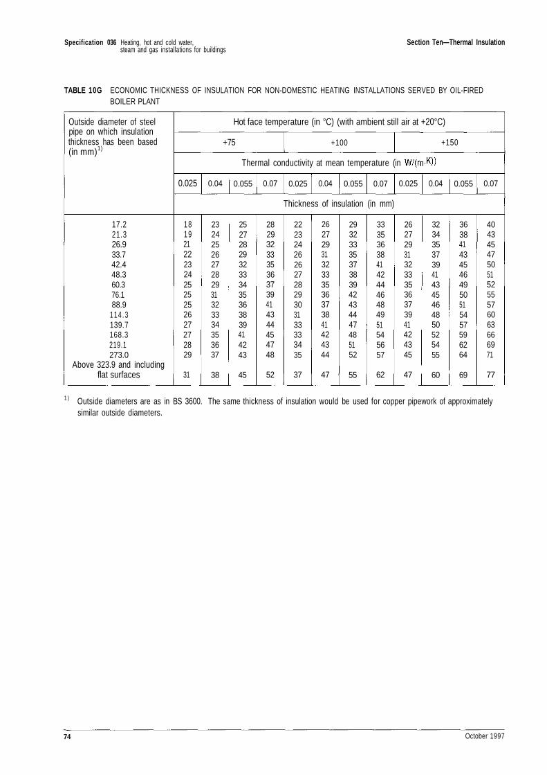
Specification 036 Section Ten—Thermal Insulation
TABLE 10G ECONOMIC THICKNESS OF INSULATION FOR NON-DOMESTIC HEATING INSTALLATIONS SERVED BY OIL-FIREDBOILER PLANT
Outside diameter of steelpipe on which insulationthickness has been based(in mm)1)
17.221.326.933.742.448.360.376.188.9
1 1 4 . 3139.7168.3219.1273.0
Above 323.9 and includingflat surfaces
Hot face temperature (in °C) (with ambient still air at +20°C)
+75 +100 +150
Thermal conductivity at mean temperature (in
0.025 0.04 0.055 0.07 0.025 0.04 0.055 0.07 0.025 0.04 0.055 0.07
Thickness of insulation (in mm)
1819212223242525252627272829
31
2324252627282931323334353637
38
2527282932333435363839414243
45
2829323335363739414344454748
52
2223242626272829303133333435
37
2627293132333536373841424344
47
2932333537383942434447485152
55
3335363841424446484951545657
62
2627293132333536373941424345
47
3234353739414345464850525455
60
3638414345464950515457596264
69
4043454750515255576063666971
77
1 ) Outside diameters are as in BS 3600. The same thickness of insulation would be used for copper pipework of approximatelysimilar outside diameters.
74 October 1997
Heating, hot and cold water,steam and gas installations for buildings
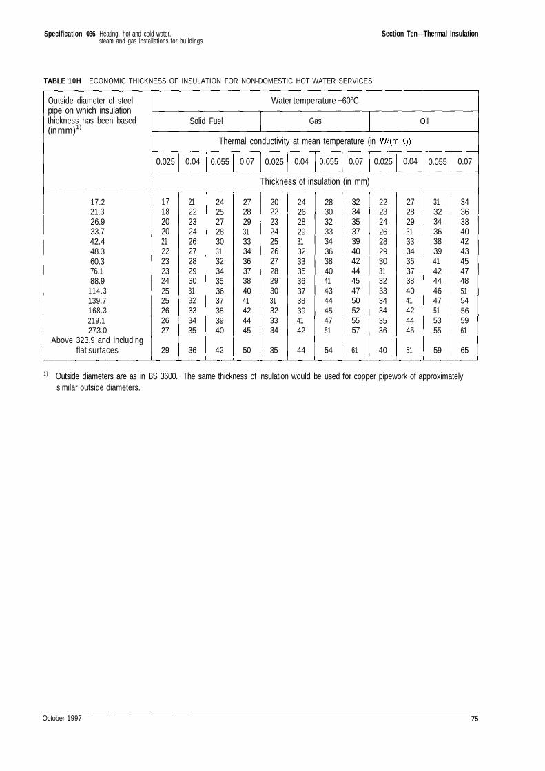
Specification 036 Section Ten—Thermal Insulation
TABLE 10H ECONOMIC THICKNESS OF INSULATION FOR NON-DOMESTIC HOT WATER SERVICES
Outside diameter of steelpipe on which insulationthickness has been based(in mm)1)
17.221.326.933.742.448.360.376.188.9
114 .3139.7168.3219.1273.0
Above 323.9 and includingflat surfaces
Water temperature +60°C
Solid Fuel Gas Oil
Thermal conductivity at mean temperature (in
0.025 0.04 0.055 0.07 0.025 0.04 0.055 0.07 0.025 0.04 0.055 0.07
Thickness of insulation (in mm)
1718202021222323242525262627
29
2122232426272829303132333435
36
2425272830313234353637383940
42
2728293133343637384041424445
50
2022232425262728293031323334
35
2426282931323335363738394142
44
2830323334363840414344454751
54
3234353739404244454750525557
61
2223242628293031323334343536
40
2728293133343637384041424445
51
3132343638394142444647515355
59
3436384042434547485154565961
65
1) Outside diameters are as in BS 3600. The same thickness of insulation would be used for copper pipework of approximatelysimilar outside diameters.
October 1997 75
Heating, hot and cold water,steam and gas installations for buildings
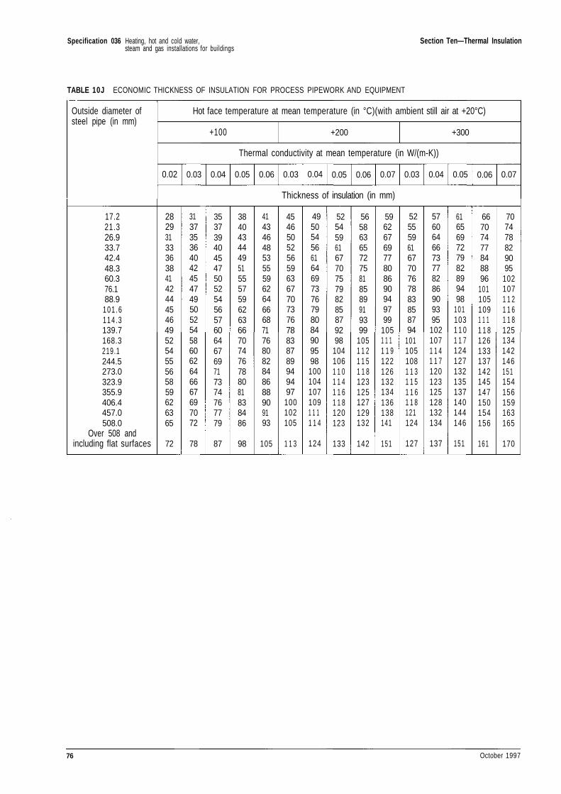
Specification 036 Section Ten—Thermal Insulation
TABLE 10J ECONOMIC THICKNESS OF INSULATION FOR PROCESS PIPEWORK AND EQUIPMENT
Outside diameter ofsteel pipe (in mm)
17.221.326.933.742.448.360.376.188.9
101.6114 .3139.7168.3219.1244.5273.0323.9355.9406.4457.0508.0
Over 508 andincluding flat surfaces
Hot face temperature at mean temperature (in °C)(with ambient still air at +20°C)
+100 +200 +300
Thermal conductivity at mean temperature (in W/(m-K))
0.02 0.03 0.04 0.05 0.06 0.03 0.04 0.05 0.06 0.07 0.03 0.04 0.05 0.06 0.07
Thickness of insulation (in mm)
282931333638414244454649525455565859626365
72
313735364042454749505254586062646667697072
78
353739404547505254565760646769717374767779
87
384043444951555759626366707476788081838486
98
414346485355596264666871768082848688909193
105
454650525659636770737678838789949497100102105
1 1 3
4950545661646973767980849095981001041071091 1 11 1 4
124
52545961677075798285879298
1041061 1 01 1 41 1 61 1 8120123
133
565863657275818589919399
1051 1 21 1 51 1 8123125127129132
142
5962676977808690949799
1051 1 11 1 9122126132134136138141
151
525559616770767883858794
1011051081 1 31 1 51 1 61 1 8121124
127
5760646673778286909395
1021071 1 41 1 7120123125128132134
137
616569727982899498
1011031 1 01 1 7124127132135137140144146
151
66707477848896
1011051091 1 11 1 8126133137142145147150154156
161
707478829095
1021071 1 21 1 61 1 8125134142146151154156159163165
170
76 October 1997
Heating, hot and cold water,steam and gas installations for buildings
Specification 036
Section Eleven—Electrical Equipment and Wiring
GENERAL
11.1.1 Unless otherwise indicated the Contractorshall provide and install all electrical equipmentnecessary for the complete installation and carry outall wiring from point(s) of supply indicated on thedrawing(s).
11.1.2 The Contractor shall be responsible for theaccuracy of all wiring diagrams provided by him andfor the correct internal wiring of all pre-wiredequipment supplied for the contract.
11.1.3 Unless otherwise indicated all electricalequipment shall be suitable for use in ambienttemperatures up to 40°C and relative humidities up to90%. Equipment shall be proof against atmosphericcorrosion, including saline air where indicated, andmaterial shall not be susceptible to mould growth orattack by vermin.
11.1.4 The electrical installation shall comply withMOD Functional Standard Specification 034 and thefollowing requirements. Any discrepancies shall bereferred to the PM who will decide on precedence.
1 1 . 2 ELECTRIC MOTORS
11.2.1 Motors shall comply with BS 2048, BS 4999and BS 5000 as appropriate and shall be of sizes andtypes to drive the equipment under normal conditionsof service without overloading. Motors greater than0.75 kW output shall be suitable for operation from athree-phase supply unless otherwise indicated oragreed with the PM.
11.2.2 Fan, pump, stoker and burner motors shallbe continuously rated. The insulation shall complywith BS 2757. Classes Y and A shall not be used.
11.2.3 Motor enclosures shall comply with BS 4999:Part 105. The degree of protection shall be IP 44, oras indicated, with the exception of the following:
a) Solid fuel boiler houses—IP54 or asindicated.
b) Condensate pumps—IP55 or as indicated.
11.2.4 Each motor circuit shall be provided with anisolator, switch or circuit breaker in the motor starter,operable under load.
11.2.5 Where a motor is not visible from the motorstarter position, or where the PM decides necessary,an isolator, switch or push-button shall be providedadjacent to or mounted on the motor. See Clauses11.3.4 and 11.3.5.
11.2.6 Motors arranged for automatic starting shallhave a label of durable material permanently affixedin a prominent position and having, in clearlyinscribed characters, the legend:
DANGER. THIS MOTOR ISAUTOMATICALLY CONTROLLED ANDMAY START WITHOUT WARNING.ISOLATE BEFORE INSPECTION.
1 1 . 3 CONTROL GEAR
11.3.1 Starters shall comply with BS EN 60947—1:1992 and be rated for utilisation category AC3 andintermittent duty, class as indicated. Unlessotherwise indicated, starters for motors up to 5kWshall be direct-on-line, and above 5kW they shall bestar-delta or other assisted start.
11.3.2 Contactor operating coils shall be suppliedat no more than 240 volts. Where operation isremotely controlled a protective fuse shall be provided.All starters shall be provided with load-breakingisolating switches which shall be lockable.
11.3.3 The control gear for each motor of morethan 0.5kW rating shall include:
a) Under-voltage protection (but see Clause11.3.4).
October 1997 77
Heating, hot and cold water,steam and gas installations for buildings

Specification 036 Section Eleven—Electrical Equipment and Wiring
b) Emergency stop push-button as indicated.
c) In each phase of a three-phase motor, ahand reset combined thermal overload andsingle-phasing protection device.
11.3.4 Isolators and switches shall be capable ofinterrupting full load current, including stalled motorcurrent, and shall be lockable.
11.3.5 Push-buttons shall be of the mushroom-headed, twist-to-reset, type arranged to directlycontrol the motor starter.
11.3.6 Motors for circulators and all other motorsunder automatic control, other than those associatedwith the firing equipment of steam boilers, shall havestarters arranged for automatic restart after powerfailure when mains voltage is restored.
11.3.7 Facilities shall be provided for alternativehand operation of automatically controlled startersand contactors.
11.3.8 Protective fuses shall be to BS 88.
1 1 . 4 ENCLOSURES
11.4.1 Control gear may be mounted within acubicle or panel as described in Section 8.4.
11.4.2 Electrical equipment shall be provided withentries for screwed conduit or for mineral insulatedcable as indicated. Large items of equipment shallhave removable gland plates to facilitate the flangingof trunking.
1 1 . 5 IMMERSION HEATERS FOR HOT WATER
11.5.1 These shall be supplied by the Contractor orissued to him as indicated and shall be of the ratingsindicated.
11.5.2 Elements shall be of the metal sheathed rodtype with the resistor embedded in refractorymaterial. Manufacture shall be from materialsrecommended by the local electricity company for thewater supply of the particular area.
11.5.3 Elements shall be firmly brazed to brass orgunmetal heads. Soft soldering will not be accepted.Heads shall be octagonal and screwed 2/4 BSPmedium fit, and provided with a jointing washer andsweating flange.
11.5.4 Heads shall be complete with connectionchambers with removable covers, having line, neutraland earth terminals and bushed cable entries orscrewed entries for conduit, as required.
11.5.5 Heaters rated up to 3kW shall comply withBS 3456: Part 1 and BS 3456 Section 2.21, except asmodified by this Specification. Other heaters shallcomply with BS 3456: Part 1 and BS 3456 Section2.21, as far as is practicable.
11.5.6 Each single-phase heater shall incorporatean adjustable thermostat having a range ofadjustment between 50°C and 80°C.
11.5.7 Each poly-phase immersion heater shall becontrolled by an adjustable thermostat having a rangeof adjustment between 50°C and 80°C installed in animmersed pocket and operating through an electricalcontactor.
1 1 . 6 FAN CONVECTORS
11.6.1 Unless otherwise indicated an adjacent 230volts 13 ampere socket or a fused-spur outlet will beprovided under separate contract to supply each fanconvector.
1 1 . 7 BONDING
11.7.1 The Contractor shall ensure that all themetallic installations which constitute 'Extraneousconductive parts' shall be electrically bonded inaccordance with BS 7671.
11.7.2 Metallic gas pipework shall be electricallycontinuous. Flanged, grooved or compression typefittings in gas pipes shall be electrically bonded. Gaspipework shall be electrically bonded to electricalearth terminals to BS 7671 and BS 7430.
11 .8 TESTING
11.8.1 The Contractor shall supply a Test Certificatefor each electrical installation and appropriate items ofelectrical equipment which are normally subject totests. Unless otherwise indicated the Certificates shallbe made up using MOD forms supplied by the PM. TheCertificates shall guarantee that the electricalinstallation or electrical equipment has been fabricated,inspected and satisfactorily tested in accordance withBS 7671 and any other relevant Regulation.
78 October 1997
Heating, hot and cold water,steam and gas installations for buildings
Specification 036
Section Twelve—Inspection, Tests andCommissioning
12.1 INSPECTIONS BY COMPETENT PERSON
12.1.1 Certain equipments and installations shallbe made available during design, fabrication,construction, installation and commissioning forinspections by a Competent Person (CP) who is asindicated. The CP will be acting as the PM'srepresentative and the Contractor shall provideinformation and access as necessary to satisfy the CPthat the particular technical and legal requirements ofthe Contract have been met. Equipment andinstallations indicated as requiring inspection(s) willnot be accepted until the CP has certified the designs,fabrication, construction, installation andperformances as relevant. The inspection and testingactivities shall be taken into account whenprogramming the Works.
12.1.2 The Contractor shall notify the PM inwriting as soon as possible after the Contract has beenawarded of the particular equipment and installationswhich require the CP's attendance. The PM will placeOrder(s) with the CP upon receipt of such notification,and the CP will make direct contact with theContractor to agree technical details and theprogramme of attendances on the Site or elsewhere asrelevant.
12.1.3 In mutual agreement with the CP theContractor shall provide detailed drawings of theequipment and installations prior to fabrication and/orconstruction and/or installation, and shall arrange forWorks and/or site visits for inspections and/orStatutory Examinations as relevant.
12.1.4 The following list of equipment andinstallations, together with their mountings andaccessories, shall be subjected to inspections by theCP:
a) Boilers: steam, HTHW, MTHW and LTHWas indicated.
b) Pressure vessels: steam receivers, airreceivers, pressurising and expansion vesselsincorporated in boiler plant unless otherwiseindicated.
c) Calorifiers, heat-exchangers and pressurevessels incorporated in steam, HTHW andMTHW heating and domestic hot watersystems.
d) Pressurised system mains and distributionpipework as indicated.
e) Fuel tanks as indicated.
f) Steel chimneys and flues as indicated.
g) Any other pressure system.
h) Other systems and equipment as indicated.
12.2 RESPONSIBILITY FOR REPORTINGINFRINGEMENT OF REGULATIONS
12.2.1 Throughout the execution of the Works theContractor shall be responsible for ensuringcompliance with all relevant safety regulationsincluding the regulations listed in Section 1.6 andshall notify the PM of any infringements whichdirectly or indirectly detract from the safe andsatisfactory operation of the installation(s), whether ornot such infringements relate to the Works or to theassociated works of others.
12.3 CLEANLINESS
12.3.1 Things for incorporation in the Works shallbe kept in protective storage until needed. Tubes andequipment shall be kept effectively plugged, capped orsealed prior to installation.
October 1997 79
Heating, hot and cold water,steam and gas installations for buildings
Specification 036 Section Twelve—Inspection, Tests and Commissioning
12.3.2 Before installations are commissioned andsubjected to the inspections and tests required inSection 12.4, they shall be thoroughly cleanedinternally and externally.
12.3.3 All items that could be damaged byscavenging or cleaning shall be suitably protected andcleaned by alternative approved methods.
12.3.4 Internal cleaning for gas installations shallinclude scavenging with steam or compressed air.
12.3.5 Fuel oil installations shall be cleaned bysteam purging or flushing with water at velocities notless than 1.5m/s. Water flushing shall includedetergent treatment as approved by the PM.
12.3.6 Steam and condensate systems shall bescavenged with steam or compressed air.
12.3.7 Internal cleaning for hot water heatinginstallations shall include flushing, chemical cleaning,passivation and final flushing to a written specificationapproved prior to starting, or as indicated. Cleaningprocedures shall be carried out in compliance with therecommendations contained in CIBSE Code 'W and theCode of Practice for the use of High Pressure WaterJetting Equipment as relevant.
12.3.8 DHWS and CWS installations shall beflushed, cleaned and disinfected to a writtenspecification approved prior to starting, or asindicated. Cleaning for these systems shall be inaccordance with the requirements andrecommendations contained in BS 6700.
12.3.9 Effluent from cleaning processes shall bedischarged into the foul-drainage system incompliance with the requirements of the local WaterCompany.
12.4 INSPECTION AND TESTS ON COMPLETION
12.4.1 Boiler plant, tanks, cylinders, pumps, etc,specified to comply with British Standards shall besubject to tests at works in accordance with therelevant BS. Materials or plant not covered by a BS,shall be subjected to a hydraulic test at works of 1.5times the maximum working pressure, or of 1.5 bar,whichever is the greater, for a period of 30 minutes.
12.4.2 Test certificates for works tests required byBritish Standards shall be submitted in duplicate tothe PM.
12.4.3 Completed hot water heating, DHWS,steam, and condensate systems shall be subjected tohydraulic pressure tests after cleaning. The systems
shall be tested to 1.5 times working pressure for notless than 30 minutes. Steam blowdown systems shallbe designed, tested and operated in accordance withHealth and Safety Executive Guidance Note PM60.Items of equipment such as safety valves and burstingdiscs set to operate below test pressure shall beisolated during testing. After satisfactory tests,systems shall be drained, dried, filled with preservingsolution or filled with treated water as indicated.
12.4.4 After being cleaned cold water systems shallbe recharged with clean water and tested as follows.Storage cisterns and distributing pipe-work shall bewatertight under working conditions of pressure withall draw-off taps closed. Water mains and servicepipework shall be subjected to a hydraulic testpressure of 9 bar or 1.5 times the maximum workingpressure, whichever is the greater. This pressureshall be maintained without measurable loss for atleast 30 minutes.
12.4.5 After being cleaned fuel oil systems shall behydraulically tested for 30 minutes to 1.5 times theworking pressure or 7 bar, as indicated, withoutleakage. Suction lines that may be subjected to sub-atmospheric pressure, shall be tested to a negativepressure of 0.3 bar for 30 minutes with a maximumloss of 0.03 bar, as detailed in BS 5410: Part 2.
12.4.6 After being cleaned gas installations shall betested for soundness and purged in accordance withIGE/UP/1 or BS 5482: Part 1 as relevant.
12.4.7 Installations, or sections thereof, which willbe embedded in the structure or concealed (inaccordance with Clause 4.1.4) shall, in addition to theabove specified tests, be individually tested as theyare laid and prior to being embedded or concealed.
12.4.8 Unless otherwise indicated, pressure testsshall be carried out on completed systems prior to theapplication of thermal insulation. Subject toagreement with the PM, sub-sections or sub-systemsmay be tested before system completion to facilitatethe insulation work. These advanced tests shall bewitnessed and certified by the PM's representative.This shall not relieve the Contractor of theresponsibility to pressure test the completed systemand show satisfactory results.
12.5 TESTS GENERALLY
12.5.1 The PM shall receive 7 calendar days noticeof all tests on items for incorporation, system and/orsub-systems on or off the site.
80 October 1997
Heating, hot and cold water,steam and gas installations for buildings
Specification 036 Section Twelve—Inspection, Tests and Commissioning
12.5.2 Unless indicated otherwise, fuel, water(other than treated water) and electricity necessary forthe operation of the heating and/or hot water serviceplants, in preliminary runs and for adjustments andtests, will be provided free of cost to the Contractor.
12.5.3 The Contractor shall supply all labour,apparatus and instruments necessary for tests.Where required by the PM, the Contractor shalldemonstrate that the accuracy of instruments usedeither by him, or by an independent specialistemployed by him, is within the tolerances permittedby the relevant BS.
12.5.4 Any defects of workmanship, materials,performance, design of equipment, maladjustments orother irregularities shall be rectified by the Contractorand the tests repeated at the Contractor's expense, tothe satisfaction of the PM.
12.7 BOILER PERFORMANCE TESTS
12.6 COMMISSIONING
12.6.1 Each installation shall be fullycommissioned in accordance with the CIBSE Codes Band W and BSRIA Application Guide AG 2/89.1—TheCommissioning of Water Systems in Buildings. Unlessotherwise indicated the Contractor shall arrange forthe commissioning engineers to survey theinstallations and submit a commissioning scheduleand programme, to the PM for comment, at least 6weeks before commencement of commissioning.
12.6.2 Commissioning shall be undertaken by theContractor or by an approved independentcommissioning specialist as indicated. The sumallocated for commissioning shall be stated separatelyin the Summary of Tender.
12.6.3 Before any commissioning is started, theContractor shall ensure that each installation hasbeen cleaned, inspected and pressure tested and thatthe requirements of Section 11.8 have been satisfied.
12.6.4 Pipe systems shall be modified in accordancewith good pipework practice as necessary prior toregulation so that flow rates with all valves open arewithin 50% of the design rates. Fluid flow rates shallbe adjusted to within 95% and 110% of design unlessotherwise agreed by the PM.
12.6.5 Results of commissioning tests shall berecorded by the Contractor on the CommissioningCertificates provided. Unless otherwise indicatedeach certificate shall be signed by the Contractor andendorsed by the PM or his representative.
12.7.1 The Contractor shall arrange forperformance tests to be carried out on each boiler, toestablish thermal efficiency at maximum combustionrate, at minimum combustion rate and at aboutmidway between when relevant. These tests shall bewitnessed by the PM together with a seniorrepresentative from the Contractor.
12.7.2 The Contractor may elect to carry out thetests on LTHW and DHWS boiler plant himself oralternatively appoint an approved independentspecialist.
12.7.3 HTHW, MTHW and steam boiler plant shallbe tested by a nominated specialist or an approvedspecialist engaged by the Contractor as indicated. Thetest shall be witnessed by the CP.
12.7.4 The tests shall demonstrate to the PM thatthe thermal efficiency of each boiler is not less thanthat guaranteed by the Contractor in his tender.
12.7.5 The boiler performance tests required byClause 12.7.1 shall comply with BS 845: Part 1, basedon flue gas losses measured at the flue gas exit fromeach boiler. The results of the tests shall be recordedon a Boiler Test Report, which shall be endorsed bythe PM or his representative.
12.7.6 Should completion of the Works and thereadiness to conduct proving tests coincide with aperiod when difficulty may be experienced in securingoperating conditions consistent with eventual designperformance, the boiler plant will be provisionallyaccepted subject to tests at a later date. This dateshall be agreed between the PM and the Contractorbut shall not be later than six months from the date ofprovisional acceptance. If the tests at this later dateconfirm the acceptability of the boiler plant, thecompletion date, for this purpose of determiningcommencement of the defect liability period, shall bethe date of provisional acceptance. If any proving testfails to meet the performance standard specified, theContractor shall make good the defect at his own costand the conditions of the contract relating to thedefect liability period shall apply to the portions of theWorks so made good until the expiration of theappropriate period or the expiration of six monthsfrom the date of such making good, whichever is thelater.
12.7.7 Boiler efficiencies shall comply with therequirements of the EC Boiler Efficiency Directive.
October 1997 81
Heating, hot and cold water,steam and gas installations for buildings
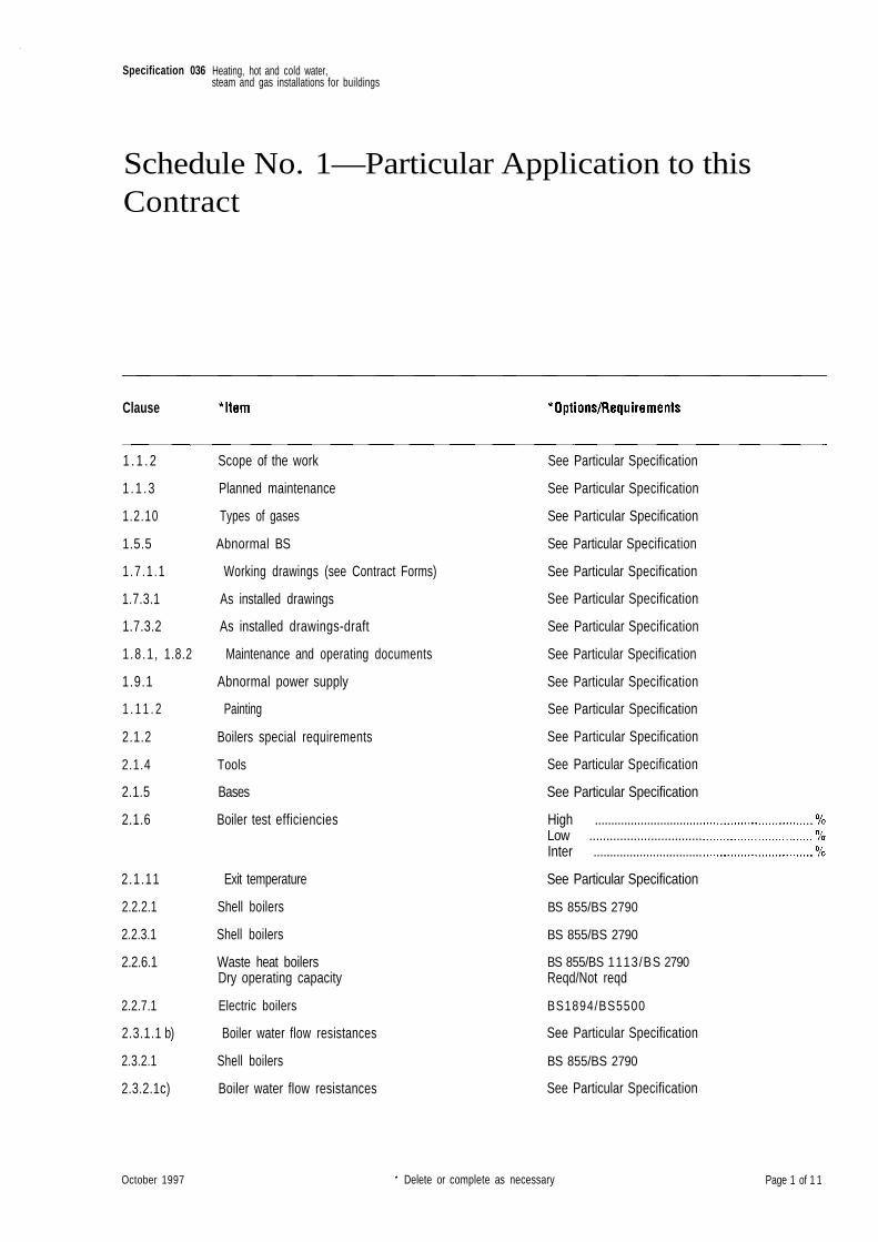
Specification 036
Schedule No. 1—Particular Application to thisContract
Clause
1 . 1 . 2 Scope of the work
1 .1 .3 Planned maintenance
1.2.10 Types of gases
1.5.5 Abnormal BS
1.7 .1 .1 Working drawings (see Contract Forms)
1.7.3.1 As installed drawings
1.7.3.2 As installed drawings-draft
1 .8 .1 , 1.8.2 Maintenance and operating documents
1.9.1 Abnormal power supply
1 . 1 1 . 2 Painting
2.1.2 Boilers special requirements
2.1.4 Tools
2.1.5 Bases
2.1.6 Boiler test efficiencies
2.1.11 Exit temperature
2.2.2.1 Shell boilers
2.2.3.1 Shell boilers
2.2.6.1 Waste heat boilersDry operating capacity
2.2.7.1 Electric boilers
2.3.1.1 b) Boiler water flow resistances
2.3.2.1 Shell boilers
2.3.2.1c) Boiler water flow resistances
See Particular Specification
See Particular Specification
See Particular Specification
See Particular Specification
See Particular Specification
See Particular Specification
See Particular Specification
See Particular Specification
See Particular Specification
See Particular Specification
See Particular Specification
See Particular Specification
See Particular Specification
High .................................Low .................................Inter .................................
See Particular Specification
BS 855/BS 2790
BS 855/BS 2790
BS 855/BS 1113/BS 2790Reqd/Not reqd
BS1894/BS5500
See Particular Specification
BS 855/BS 2790
See Particular Specification
October 1997 Delete or complete as necessary Page 1 of 1 1
Heating, hot and cold water,steam and gas installations for buildings
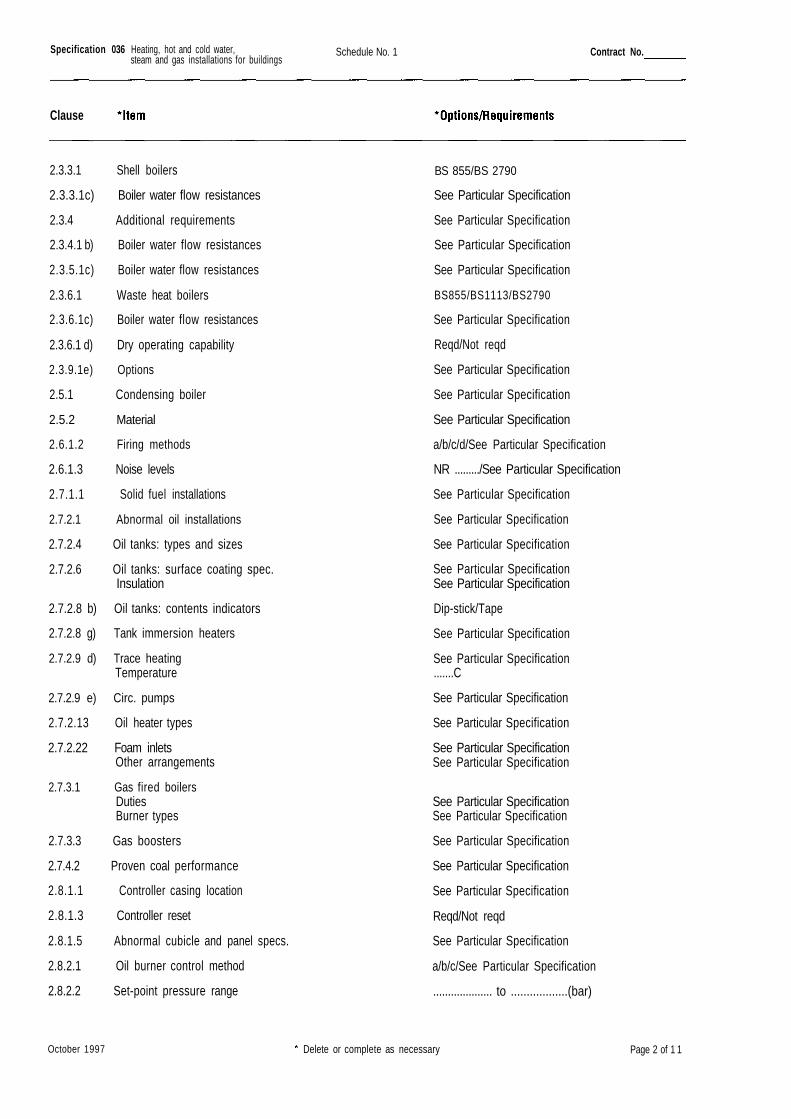
Specification 036 Schedule No. 1 Contract No.
Clause
2.3.3.1 Shell boilers
2.3.3.1c) Boiler water flow resistances
2.3.4 Additional requirements
2.3.4.1 b) Boiler water flow resistances
2.3.5.1c) Boiler water flow resistances
2.3.6.1 Waste heat boilers
2.3.6.1c) Boiler water flow resistances
2.3.6.1 d) Dry operating capability
2.3.9.1e) Options
2.5.1 Condensing boiler
2.5.2 Material
2.6.1.2 Firing methods
2.6.1.3 Noise levels
2.7.1.1 Solid fuel installations
2.7.2.1 Abnormal oil installations
2.7.2.4 Oil tanks: types and sizes
2.7.2.6 Oil tanks: surface coating spec.Insulation
2.7.2.8 b) Oil tanks: contents indicators
2.7.2.8 g) Tank immersion heaters
2.7.2.9 d) Trace heatingTemperature
2.7.2.9 e) Circ. pumps
2.7.2.13 Oil heater types
2.7.2.22 Foam inletsOther arrangements
2.7.3.1 Gas fired boilersDutiesBurner types
2.7.3.3 Gas boosters
2.7.4.2 Proven coal performance
2.8.1.1 Controller casing location
2.8.1.3 Controller reset
2.8.1.5 Abnormal cubicle and panel specs.
2.8.2.1 Oil burner control method
2.8.2.2 Set-point pressure range
BS 855/BS 2790
See Particular Specification
See Particular Specification
See Particular Specification
See Particular Specification
BS855/BS1113/BS2790
See Particular Specification
Reqd/Not reqd
See Particular Specification
See Particular Specification
See Particular Specification
a/b/c/d/See Particular Specification
NR ........./See Particular Specification
See Particular Specification
See Particular Specification
See Particular Specification
See Particular SpecificationSee Particular Specification
Dip-stick/Tape
See Particular Specification
See Particular Specification.......C
See Particular Specification
See Particular Specification
See Particular SpecificationSee Particular Specification
See Particular SpecificationSee Particular Specification
See Particular Specification
See Particular Specification
See Particular Specification
Reqd/Not reqd
See Particular Specification
a/b/c/See Particular Specification
.................... to ..................(bar)
October 1997 Delete or complete as necessary Page 2 of 1 1
Heating, hot and cold water,steam and gas installations for buildings
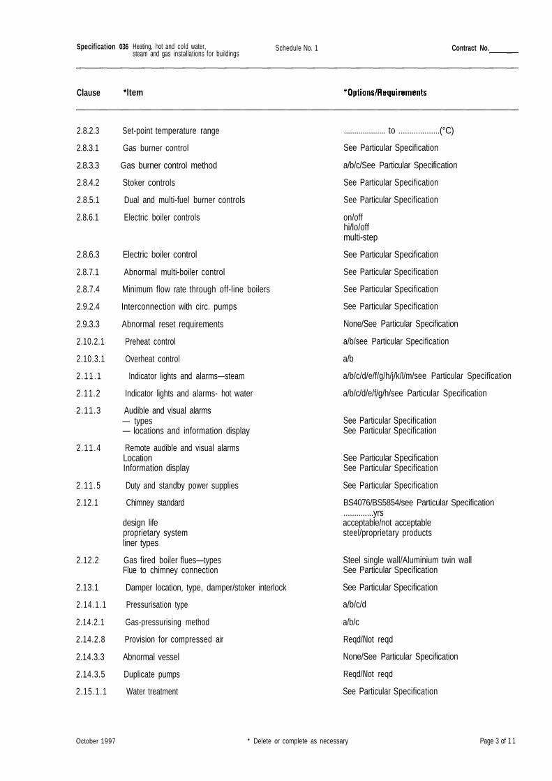
Specification 036 Schedule No. 1 Contract No.
Clause *ltem
2.8.2.3 Set-point temperature range
2.8.3.1 Gas burner control
2.8.3.3 Gas burner control method
2.8.4.2 Stoker controls
2.8.5.1 Dual and multi-fuel burner controls
2.8.6.1 Electric boiler controls
2.8.6.3 Electric boiler control
2.8.7.1 Abnormal multi-boiler control
2.8.7.4 Minimum flow rate through off-line boilers
2.9.2.4 Interconnection with circ. pumps
2.9.3.3 Abnormal reset requirements
2.10.2.1 Preheat control
2.10.3.1 Overheat control
2 . 1 1 . 1 Indicator lights and alarms—steam
2.11.2 Indicator lights and alarms- hot water
2.11.3 Audible and visual alarms— types— locations and information display
2 .11 .4 Remote audible and visual alarmsLocationInformation display
2.11 .5 Duty and standby power supplies
2.12.1 Chimney standard
design lifeproprietary systemliner types
2.12.2 Gas fired boiler flues—typesFlue to chimney connection
2.13.1 Damper location, type, damper/stoker interlock
2.14.1.1 Pressurisation type
2.14.2.1 Gas-pressurising method
2.14.2.8 Provision for compressed air
2.14.3.3 Abnormal vessel
2.14.3.5 Duplicate pumps
2.15.1 .1 Water treatment
.................... to ...................(°C)
See Particular Specification
a/b/c/See Particular Specification
See Particular Specification
See Particular Specification
on/offhi/lo/offmulti-step
See Particular Specification
See Particular Specification
See Particular Specification
See Particular Specification
None/See Particular Specification
a/b/see Particular Specification
a/b
a/b/c/d/e/f/g/h/j/k/l/m/see Particular Specification
a/b/c/d/e/f/g/h/see Particular Specification
See Particular SpecificationSee Particular Specification
See Particular SpecificationSee Particular Specification
See Particular Specification
BS4076/BS5854/see Particular Specification..............yrsacceptable/not acceptablesteel/proprietary products
Steel single wall/Aluminium twin wallSee Particular Specification
See Particular Specification
a/b/c/d
a/b/c
Reqd/l\lot reqd
None/See Particular Specification
Reqd/l\lot reqd
See Particular Specification
October 1997 * Delete or complete as necessary Page 3 of 1 1
Heating, hot and cold water,steam and gas installations for buildings
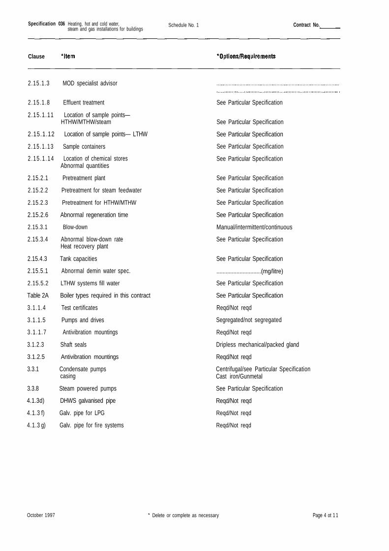
Specification 036 Schedule No. 1 Contract No.
Clause
2.15.1.3 MOD specialist advisor
2.15.1.8 Effluent treatment
2.15.1.11 Location of sample points—HTHW/MTHW/steam
2.15.1.12 Location of sample points— LTHW
2.15 .1 .13 Sample containers
2 . 1 5 . 1 . 1 4 Location of chemical storesAbnormal quantities
2.15.2.1 Pretreatment plant
2.15.2.2 Pretreatment for steam feedwater
2.15.2.3 Pretreatment for HTHW/MTHW
2.15.2.6 Abnormal regeneration time
2.15.3.1 Blow-down
2.15.3.4 Abnormal blow-down rateHeat recovery plant
2.15.4.3 Tank capacities
2.15.5.1 Abnormal demin water spec.
2.15.5.2 LTHW systems fill water
Table 2A Boiler types required in this contract
3.1.1.4 Test certificates
3.1.1.5 Pumps and drives
3.1 .1 .7 Antivibration mountings
3.1.2.3 Shaft seals
3.1.2.5 Antivibration mountings
3.3.1 Condensate pumpscasing
3.3.8 Steam powered pumps
4.1.3d) DHWS galvanised pipe
4.1.3 f) Galv. pipe for LPG
4.1.3 g) Galv. pipe for fire systems
See Particular Specification
See Particular Specification
See Particular Specification
See Particular Specification
See Particular Specification
See Particular Specification
See Particular Specification
See Particular Specification
See Particular Specification
Manual/intermittent/continuous
See Particular Specification
See Particular Specification
.............................(mg/litre)
See Particular Specification
See Particular Specification
Reqd/Not reqd
Segregated/not segregated
Reqd/Not reqd
Dripless mechanical/packed gland
Reqd/Not reqd
Centrifugal/see Particular SpecificationCast iron/Gunmetal
See Particular Specification
Reqd/Not reqd
Reqd/Not reqd
Reqd/Not reqd
October 1997 Delete or complete as necessary Page 4 ot 1 1
Heating, hot and cold water,steam and gas installations for buildings
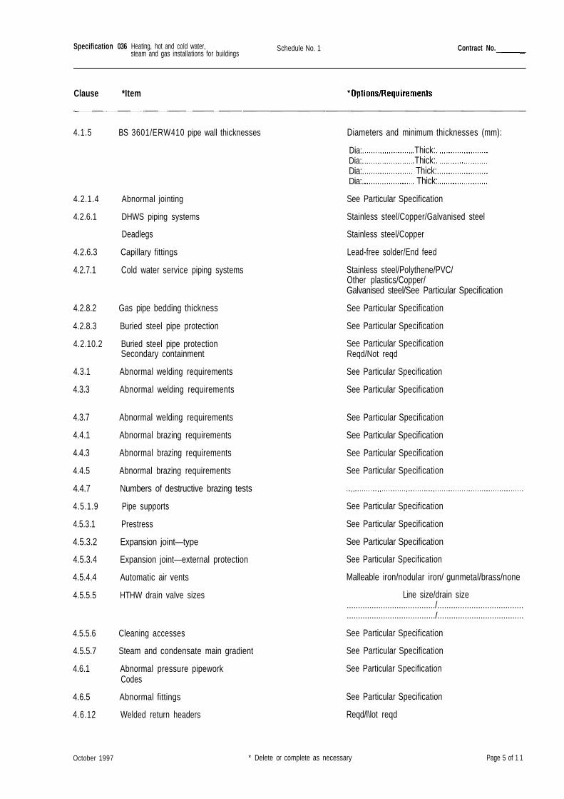
Specification 036 Schedule No. 1 Contract No.
Clause *Item
4.1.5 BS 3601/ERW410 pipe wall thicknesses Diameters and minimum thicknesses (mm):
4.2.1.4 Abnormal jointing
4.2.6.1 DHWS piping systems
Deadlegs
4.2.6.3 Capillary fittings
4.2.7.1 Cold water service piping systems
4.2.8.2 Gas pipe bedding thickness
4.2.8.3 Buried steel pipe protection
4.2.10.2 Buried steel pipe protectionSecondary containment
4.3.1 Abnormal welding requirements
4.3.3 Abnormal welding requirements
4.3.7 Abnormal welding requirements
4.4.1 Abnormal brazing requirements
4.4.3 Abnormal brazing requirements
4.4.5 Abnormal brazing requirements
4.4.7 Numbers of destructive brazing tests
4.5.1.9 Pipe supports
4.5.3.1 Prestress
4.5.3.2 Expansion joint—type
4.5.3.4 Expansion joint—external protection
4.5.4.4 Automatic air vents
4.5.5.5 HTHW drain valve sizes
4.5.5.6 Cleaning accesses
4.5.5.7 Steam and condensate main gradient
4.6.1 Abnormal pressure pipeworkCodes
4.6.5 Abnormal fittings
4.6.12 Welded return headers
Dia:.Dia:.Dia:.Dia:.
. Thick:.
. Thick:.Thick:.
. Thick:.
See Particular Specification
Stainless steel/Copper/Galvanised steel
Stainless steel/Copper
Lead-free solder/End feed
Stainless steel/Polythene/PVC/Other plastics/Copper/Galvanised steel/See Particular Specification
See Particular Specification
See Particular Specification
See Particular SpecificationReqd/Not reqd
See Particular Specification
See Particular Specification
See Particular Specification
See Particular Specification
See Particular Specification
See Particular Specification
See Particular Specification
See Particular Specification
See Particular Specification
See Particular Specification
Malleable iron/nodular iron/ gunmetal/brass/none
Line size/drain size......................................./............................................................................./......................................
See Particular Specification
See Particular Specification
See Particular Specification
See Particular Specification
Reqd/l\lot reqd
October 1997 * Delete or complete as necessary Page 5 of 1 1
Heating, hot and cold water,steam and gas installations for buildings
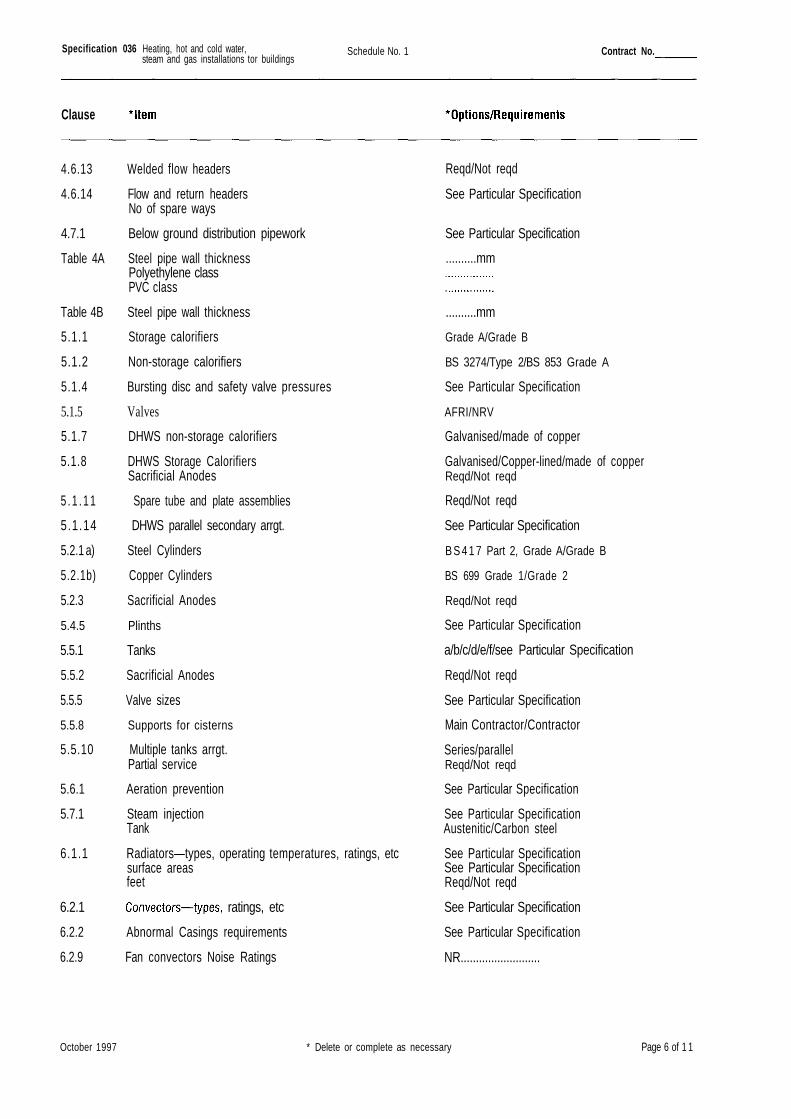
Specification 036 Schedule No. 1 Contract No.
Clause
4.6.13 Welded flow headers
4.6.14 Flow and return headersNo of spare ways
4.7.1 Below ground distribution pipework
Table 4A Steel pipe wall thicknessPolyethylene classPVC class
Table 4B Steel pipe wall thickness
5.1.1 Storage calorifiers
5.1.2 Non-storage calorifiers
5.1.4 Bursting disc and safety valve pressures
5.1.5 Valves
5.1.7 DHWS non-storage calorifiers
5.1.8 DHWS Storage CalorifiersSacrificial Anodes
5 . 1 . 1 1 Spare tube and plate assemblies
5.1.14 DHWS parallel secondary arrgt.
5.2.1 a) Steel Cylinders
5.2.1b) Copper Cylinders
5.2.3 Sacrificial Anodes
5.4.5 Plinths
5.5.1 Tanks
5.5.2 Sacrificial Anodes
5.5.5 Valve sizes
5.5.8 Supports for cisterns
5.5.10 Multiple tanks arrgt.Partial service
5.6.1 Aeration prevention
5.7.1 Steam injectionTank
6.1.1 Radiators—types, operating temperatures, ratings, etcsurface areasfeet
6.2.1 ratings, etc
6.2.2 Abnormal Casings requirements
6.2.9 Fan convectors Noise Ratings
Reqd/Not reqd
See Particular Specification
See Particular Specification
..........mm
..........mm
Grade A/Grade B
BS 3274/Type 2/BS 853 Grade A
See Particular Specification
AFRI/NRV
Galvanised/made of copper
Galvanised/Copper-lined/made of copperReqd/Not reqd
Reqd/Not reqd
See Particular Specification
B S 4 1 7 Part 2, Grade A/Grade B
BS 699 Grade 1/Grade 2
Reqd/Not reqd
See Particular Specification
a/b/c/d/e/f/see Particular Specification
Reqd/Not reqd
See Particular Specification
Main Contractor/Contractor
Series/parallelReqd/Not reqd
See Particular Specification
See Particular SpecificationAustenitic/Carbon steel
See Particular SpecificationSee Particular SpecificationReqd/Not reqd
See Particular Specification
See Particular Specification
NR..........................
October 1997 * Delete or complete as necessary Page 6 of 1 1
Heating, hot and cold water,steam and gas installations tor buildings
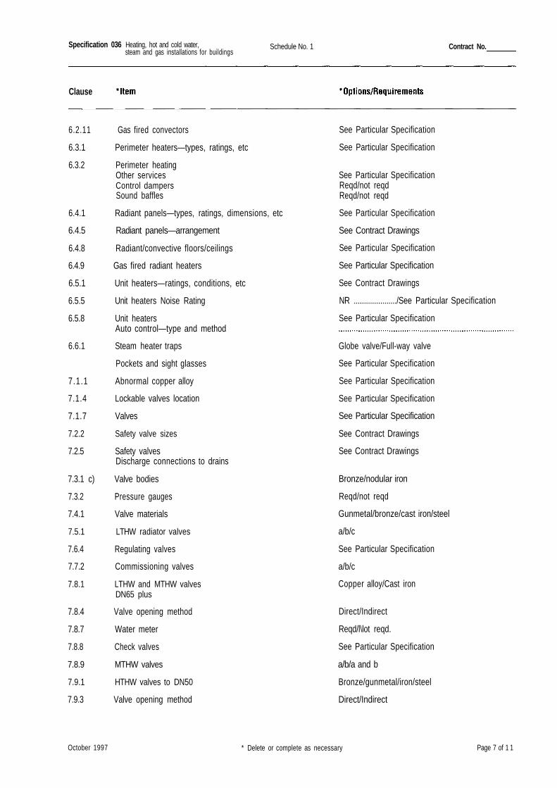
Specification 036 Schedule No. 1 Contract No.
Clause
6.2.11 Gas fired convectors
6.3.1 Perimeter heaters—types, ratings, etc
6.3.2 Perimeter heatingOther servicesControl dampersSound baffles
6.4.1 Radiant panels—types, ratings, dimensions, etc
6.4.5 Radiant panels—arrangement
6.4.8 Radiant/convective floors/ceilings
6.4.9 Gas fired radiant heaters
6.5.1 Unit heaters—ratings, conditions, etc
6.5.5 Unit heaters Noise Rating
6.5.8 Unit heatersAuto control—type and method
6.6.1 Steam heater traps
Pockets and sight glasses
7.1.1 Abnormal copper alloy
7.1.4 Lockable valves location
7.1.7 Valves
7.2.2 Safety valve sizes
7.2.5 Safety valvesDischarge connections to drains
7.3.1 c) Valve bodies
7.3.2 Pressure gauges
7.4.1 Valve materials
7.5.1 LTHW radiator valves
7.6.4 Regulating valves
7.7.2 Commissioning valves
7.8.1 LTHW and MTHW valvesDN65 plus
7.8.4 Valve opening method
7.8.7 Water meter
7.8.8 Check valves
7.8.9 MTHW valves
7.9.1 HTHW valves to DN50
7.9.3 Valve opening method
See Particular Specification
See Particular Specification
See Particular SpecificationReqd/not reqdReqd/not reqd
See Particular Specification
See Contract Drawings
See Particular Specification
See Particular Specification
See Contract Drawings
NR ...................../See Particular Specification
See Particular Specification
Globe valve/Full-way valve
See Particular Specification
See Particular Specification
See Particular Specification
See Particular Specification
See Contract Drawings
See Contract Drawings
Bronze/nodular iron
Reqd/not reqd
Gunmetal/bronze/cast iron/steel
a/b/c
See Particular Specification
a/b/c
Copper alloy/Cast iron
Direct/Indirect
Reqd/l\lot reqd.
See Particular Specification
a/b/a and b
Bronze/gunmetal/iron/steel
Direct/Indirect
October 1997 * Delete or complete as necessary Page 7 of 1 1
Heating, hot and cold water,steam and gas installations for buildings
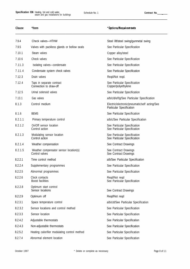
Specification 036 Schedule No. 1 Contract No.
Clause *ltem
7.9.4 Check valves—HTHW
7.9.5 Valves with packless glands or bellow seals
7.10.1 Steam valves
7.10.6 Check valves
7.11.3 Isolating valves—condensate
7.11.4 Condensate system check valves
7.12.3 Drain valves
7.12.4 Taps in separate contractConnection to draw-off
7.12.5 Urinal solenoid valves
7.13.1 Gas valves
8.1.3 Control medium
8.1.6 BEMS
8.2.1.1 Primary temperature control
8.2.1.2 On/Off sensor locationControl action
8.2.1.3 Modulating sensor locationControl action
8.2.1.4 Weather compensation
8.2.1.5 Weather compensator sensor location(s)Control valves
8.2.2.1 Time control method
8.2.2.4 Supplementary programmes
8.2.2.5 Abnormal programmes
8.2.2.6 Clock contactsBoost facilities
8.2.2.8 Optimum start controlSensor locations
8.2.2.9 Optimum off
8.2.3.1 Space temperature control
8.2.3.2 Sensor locations and control method
8.2.3.3 Sensor location
8.2.4.2 Adjustable thermostats
8.2.4.3 Non-adjustable thermostats
8.2.5.2 Heating calorifier modulating control method
8.2.7.4 Abnormal element location
Steel lift/steel swing/gunmetal swing
See Particular Specification
Copper alloy/steel
See Particular Specification
See Particular Specification
See Particular Specification
Reqd/Not reqd.
See Particular SpecificationCopper/polyethylene
See Particular Specification
a/b/c/d/e/f/g/See Particular Specification
Electric/electronic/pneumatic/self acting/SeeParticular Specification
See Particular Specification
a/b/c/See Particular Specification
See Particular SpecificationSee Particular Specification
See Particular SpecificationSee Particular Specification
See Contract Drawings
See Contract DrawingsSee Contract Drawings
a/b/See Particular Specification
See Particular Specification
See Particular Specification
Reqd/Not reqdSee Particular Specification
See Contract Drawings
Reqd/Not reqd
a/b/c/d/See Particular Specification
See Particular Specification
See Particular Specification
See Particular Specification
See Particular Specification
See Particular Specification
See Particular Specification
October 1997 * Delete or complete as necessary Page 8 of 1 1
Heating, hot and cold water,steam and gas installations for buildings
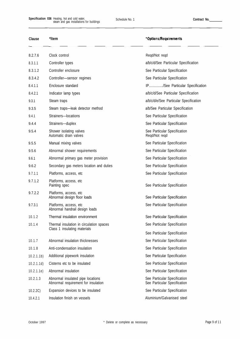
Specification 036 Schedule No. 1 Contract No.
Clause *ltem
Clock control
Controller types
Controller enclosure
Controller—sensor regimes
Enclosure standard
Indicator lamp types
Steam traps
Steam traps—leak detector method
Strainers—locations
Strainers—duplex
Shower isolating valvesAutomatic drain valves
Manual mixing valves
Abnormal shower requirements
Abnormal primary gas meter provision
Secondary gas meters location and duties
Platforms, access, etc
Platforms, access, etcPainting spec
Platforms, access, etcAbnormal design floor loads
Platforms, access, etcAbnormal handrail design loads
Thermal insulation environment
Thermal insulation in circulation spacesClass 1 insulating materials
Abnormal insulation thicknesses
Anti-condensation insulation
Additional pipework insulation
Cisterns etc to be insulated
Abnormal insulation
Abnormal insulated pipe locationsAbnormal requirement for insulation
Expansion devices to be insulated
Insulation finish on vessels
Reqd/Not reqd
a/b/c/d/See Particular Specification
See Particular Specification
See Particular Specification
IP.............../See Particular Specification
a/b/c/d/See Particular Specification
a/b/c/d/e/See Particular Specification
a/b/See Particular Specification
See Particular Specification
See Particular Specification
See Particular SpecificationReqd/Not reqd
See Particular Specification
See Particular Specification
See Particular Specification
See Particular Specification
See Particular Specification
See Particular Specification
See Particular Specification
See Particular Specification
See Particular Specification
See Particular Specification
See Particular Specification
See Particular Specification
See Particular Specification
See Particular Specification
See Particular Specification
See Particular Specification
See Particular SpecificationSee Particular Specification
See Particular Specification
Aluminium/Galvanised steel
October 1997 * Delete or complete as necessary Page 9 of 1 1
Heating, hot and cold water,steam and gas installations for buildings
8.2.7.6
8.3.1.1
8.3.1.2
8.3.4.2
8.4.1.1
8.4.2.1
9.3.1
9.3.5
9.4.1
9.4.4
9.5.4
9.5.5
9.5.6
9.6.1
9.6.2
9.7.1.1
9.7.1.2
9.7.2.2
9.7.3.1
10.1.2
10.1.4
10 .1 .7
10.1.8
10.2 .1 .1b)
10.2 .1 .1d)
10 .2 .1 .1e)
10.2.1.3
10.2.2C)
10.4.2.1
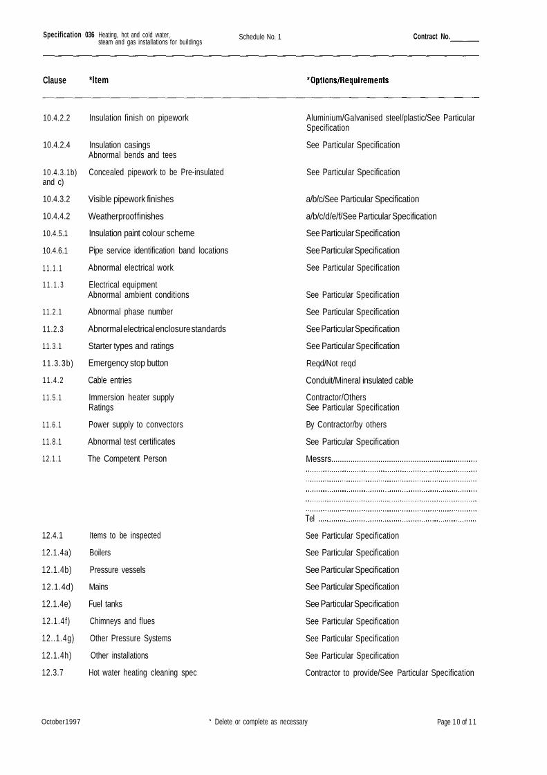
Specification 036 Schedule No. 1 Contract No.
Clause *ltem
Insulation finish on pipework
Insulation casingsAbnormal bends and tees
Concealed pipework to be Pre-insulated
Visible pipework finishes
Weatherproof finishes
Insulation paint colour scheme
Pipe service identification band locations
Abnormal electrical work
Electrical equipmentAbnormal ambient conditions
Abnormal phase number
Abnormal electrical enclosure standards
Starter types and ratings
Emergency stop button
Cable entries
Immersion heater supplyRatings
Power supply to convectors
Abnormal test certificates
The Competent Person
Aluminium/Galvanised steel/plastic/See ParticularSpecification
See Particular Specification
See Particular Specification
a/b/c/See Particular Specification
a/b/c/d/e/f/See Particular Specification
See Particular Specification
See Particular Specification
See Particular Specification
See Particular Specification
See Particular Specification
See Particular Specification
See Particular Specification
Reqd/Not reqd
Conduit/Mineral insulated cable
Contractor/OthersSee Particular Specification
By Contractor/by others
See Particular Specification
Messrs...................................................
Tel
12.4.1 Items to be inspected
12.1.4a) Boilers
12.1.4b) Pressure vessels
12.1.4d) Mains
12.1.4e) Fuel tanks
12.1.4f) Chimneys and flues
12..1.4g) Other Pressure Systems
12.1.4h) Other installations
12.3.7 Hot water heating cleaning spec
See Particular Specification
See Particular Specification
See Particular Specification
See Particular Specification
See Particular Specification
See Particular Specification
See Particular Specification
See Particular Specification
Contractor to provide/See Particular Specification
October 1997 Delete or complete as necessary Page 1 0 of 1 1
Heating, hot and cold water,steam and gas installations for buildings
10.4.2.2
10.4.2.4
10.4.3.1b)and c)
10.4.3.2
10.4.4.2
10.4.5.1
10.4.6.1
1 1 . 1 . 1
1 1 . 1 . 3
11.2.1
11.2.3
11.3.1
11.3.3b)
11.4.2
1 1 . 5 . 1
11 .6 .1
11.8.1
12.1 .1
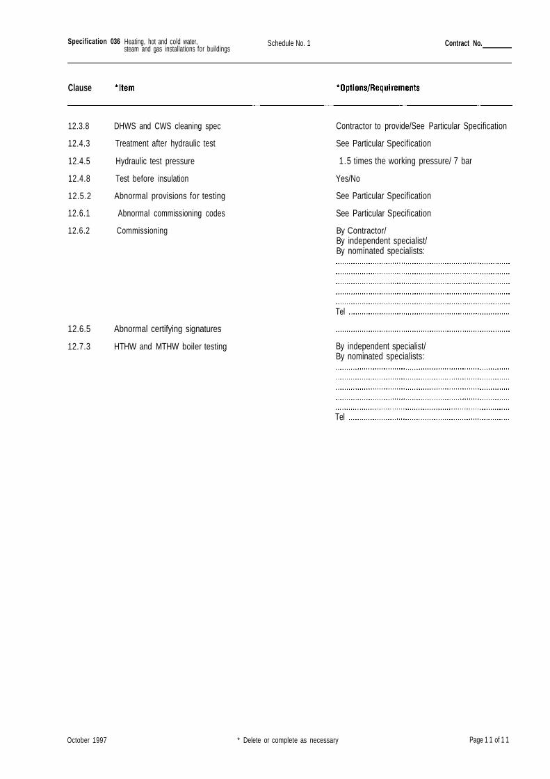
Specification 036 Schedule No. 1 Contract No.
Clause
12.3.8 DHWS and CWS cleaning spec
12.4.3 Treatment after hydraulic test
12.4.5 Hydraulic test pressure
12.4.8 Test before insulation
12.5.2 Abnormal provisions for testing
12.6.1 Abnormal commissioning codes
12.6.2 Commissioning
Contractor to provide/See Particular Specification
See Particular Specification
1.5 times the working pressure/ 7 bar
Yes/No
See Particular Specification
See Particular Specification
By Contractor/By independent specialist/By nominated specialists:
12.6.5 Abnormal certifying signatures
12.7.3 HTHW and MTHW boiler testing
Tel
By independent specialist/By nominated specialists:
Tel
October 1997 * Delete or complete as necessary Page 1 1 of 1 1
Heating, hot and cold water,steam and gas installations for buildings
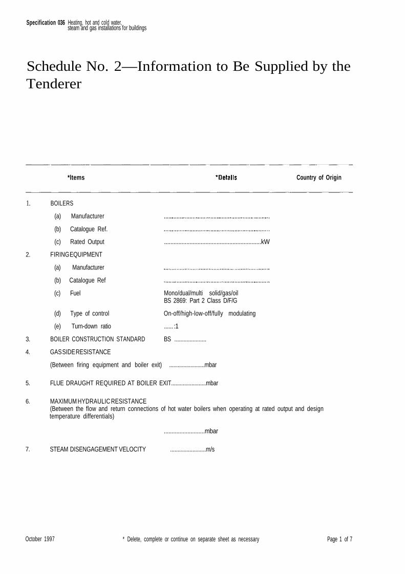
Specification 036
Schedule No. 2—Information to Be Supplied by theTenderer
*ltems Country of Origin
.............................................................kW
Mono/dual/multi solid/gas/oilBS 2869: Part 2 Class D/F/G
On-off/high-low-off/fully modulating
...... :1
BS .....................
October 1997 * Delete, complete or continue on separate sheet as necessary Page 1 of 7
Heating, hot and cold water,steam and gas installations for buildings
GAS SIDE RESISTANCE
(Between firing equipment and boiler exit) .........................mbar
FLUE DRAUGHT REQUIRED AT BOILER EXIT........................mbar
MAXIMUM HYDRAULIC RESISTANCE(Between the flow and return connections of hot water boilers when operating at rated output and designtemperature differentials)
..........................mbar
STEAM DISENGAGEMENT VELOCITY ........................m/s
1.
2.
3.
4.
5.
6.
7.
BOILERS
(a) Manufacturer
(b) Catalogue Ref.
(c) Rated Output
FIRING EQUIPMENT
(a) Manufacturer
(b) Catalogue Ref
(c) Fuel
(d) Type of control
(e) Turn-down ratio
BOILER CONSTRUCTION STANDARD
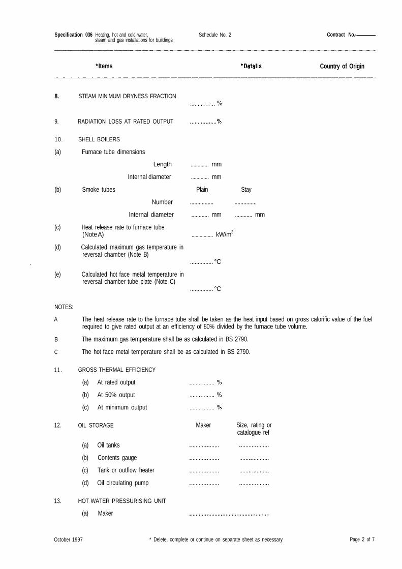
Specification 036 Schedule No. 2 Contract No.-
* Items Country of Origin
8. STEAM MINIMUM DRYNESS FRACTION
10. SHELL BOILERS
(a) Furnace tube dimensions
Length ............. mm
Internal diameter ............. mm
(b) Smoke tubes Plain Stay
Number ................ ...............
Internal diameter ............ mm ............ mm
(c) Heat release rate to furnace tube(Note A) ................ kW/m3
(d) Calculated maximum gas temperature inreversal chamber (Note B)
............... °C
(e) Calculated hot face metal temperature inreversal chamber tube plate (Note C)
............... °C
NOTES:
A
B
C
1 1 .
The heat release rate to the furnace tube shall be taken as the heat input based on gross calorific value of the fuelrequired to give rated output at an efficiency of 80% divided by the furnace tube volume.
The maximum gas temperature shall be as calculated in BS 2790.
The hot face metal temperature shall be as calculated in BS 2790.
GROSS THERMAL EFFICIENCY
(a) At rated output
(b) At 50% output
(c) At minimum output
12.
13.
OIL STORAGE
(a) Oil tanks
(b) Contents gauge
(c) Tank or outflow heater
(d) Oil circulating pump
HOT WATER PRESSURISING UNIT
(a) Maker
Maker Size, rating orcatalogue ref
October 1997 * Delete, complete or continue on separate sheet as necessary Page 2 of 7
Heating, hot and cold water,steam and gas installations for buildings
9. RADIATION LOSS AT RATED OUTPUT
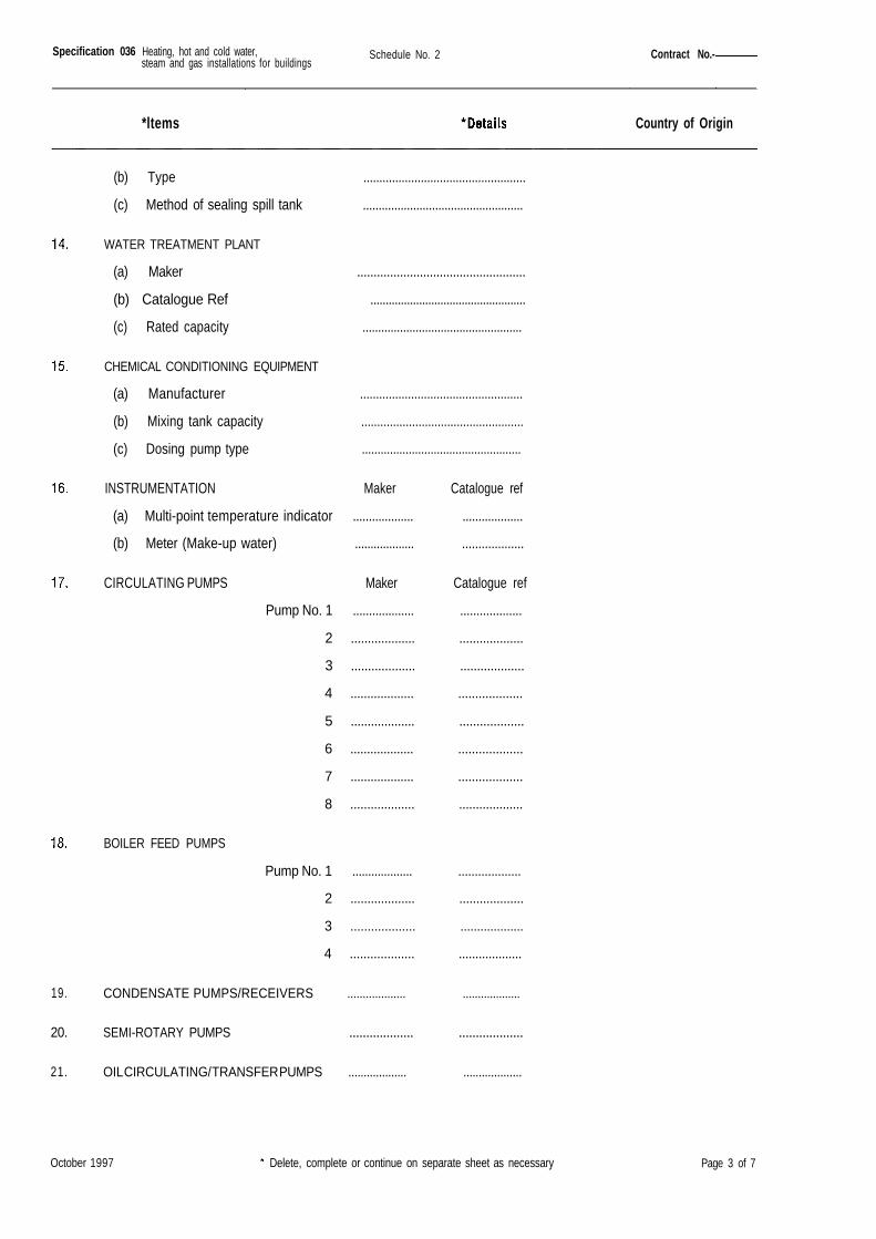
Specification 036 Schedule No. 2 Contract No.-
*ltems Country of Origin
(b) Type ...................................................
(c) Method of sealing spill tank ...................................................
WATER TREATMENT PLANT
(a) Maker ...................................................
(b) Catalogue Ref ...................................................
(c) Rated capacity ...................................................
CHEMICAL CONDITIONING EQUIPMENT
(a) Manufacturer ...................................................
(b) Mixing tank capacity ...................................................
(c) Dosing pump type ...................................................
INSTRUMENTATION Maker Catalogue ref
(a) Multi-point temperature indicator ................... ...................
(b) Meter (Make-up water) ................... ...................
CIRCULATING PUMPS Maker Catalogue ref
Pump No. 1 ................... ...................
2 ................... ...................
3 ................... ...................
4 ................... ...................
5 ................... ...................
6 ................... ...................
7 ................... ...................
8 ................... ...................
BOILER FEED PUMPS
Pump No. 1 ................... ...................
2 ................... ...................
3 ................... ...................
4 ................... ...................
October 1997 Delete, complete or continue on separate sheet as necessary Page 3 of 7
Heating, hot and cold water,steam and gas installations for buildings
19.
20.
21.
CONDENSATE PUMPS/RECEIVERS ................... ...................
SEMI-ROTARY PUMPS ................... ...................
OIL CIRCULATING/ TRANSFER PUMPS ................... ...................
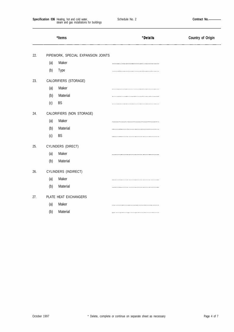
Specification 036
Country of Origin
22. PIPEWORK, SPECIAL EXPANSION JOINTS
(a) Maker
(b) Type
23. CALORIFIERS (STORAGE)
(a) Maker
(b) Material
(c) BS
24. CALORIFIERS (NON STORAGE)
(a) Maker
(b) Material
(c) BS
25. CYLINDERS (DIRECT)
(a) Maker
(b) Material
26. CYLINDERS (INDIRECT)
(a) Maker
(b) Material
27. PLATE HEAT EXCHANGERS
(a) Maker
(b) Material
October 1997 * Delete, complete or continue on separate sheet as necessary Page 4 of 7
Contract No.Schedule No. 2Heating, hot and cold water,steam and gas installations for buildings
*ltems

Specification 036
Country of Origin
28. SPACE HEATING EQUIPMENT Maker Size, rating orcatalogue ref
Radiators ................... ...................
Convectors, natural ................... ...................
Convectors, fan ................... ...................
Perimeter heaters ................... ...................
Radiant panels ................... ...................
Radiant strips ................... ...................
Radiant ceilings ................... ...................
Underfloor heating ................... ...................
Unit heaters ................... ...................
(State type (a), (b) or (c). See Clauses6.5.2 and 6.5.3. If Type (c) givesdetails of anti-corrosion protection)
October 1997 * Delete, complete or continue on separate sheet as necessary Page 5 of 7
Heating, hot and cold water,steam and gas installations for buildings
Schedule No. 2 Contract No
*ltems
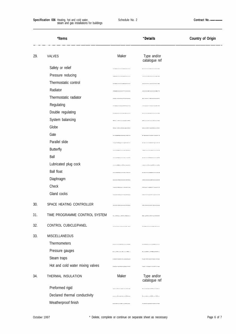
Specification 036 Schedule No. 2 Contract No
*ltems Country of Origin
VALVES
Safety or relief
Pressure reducing
Thermostatic control
Radiator
Thermostatic radiator
Regulating
Double regulating
System balancing
Globe
Gate
Parallel slide
Butterfly
Ball
Lubricated plug cock
Ball float
Diaphragm
Check
Gland cocks
SPACE HEATING CONTROLLER
TIME PROGRAMME CONTROL SYSTEM
CONTROL CUBICLE/PANEL
MISCELLANEOUS
Thermometers
Pressure gauges
Steam traps
Hot and cold water mixing valves
THERMAL INSULATION
Preformed rigid
Declared thermal conductivity
Weatherproof finish
Type and/orcatalogue ref
Type and/orcatalogue ref
October 1997 * Delete, complete or continue on separate sheet as necessary Page 6 of 7
Heating, hot and cold water,steam and gas installations for buildings
29.
30.
31.
32.
33.
34.
Maker
Maker
Specification 036 Schedule No. 2 Contract No.-
*ltems Country of Origin
35. OTHER EQUIPMENT
36. COMMISSIONING
By Contractor
By Commissioning Specialist
37. BOILER PERFORMANCE TEST
By Contractor
By independent specialist/Company
38. DRAWINGS/PAMPHLETS SUPPLIEDWITH TENDER
Yes/No
Name: .
Yes/No
Name: .
Signed (as in Tender) ....................................................................................
For and on behalf of............................................................................ Date
October 1997 * Delete, complete or continue on separate sheet as necessary Page 7 of 7
Heating, hot and cold water,steam and gas installations for buildings
Specification 036
If you have comments on this document please fill in a photocopy of this form and send it to DEO (Works).Please do not use the shaded areas of the form.
Section/Clause/Sub-clause or Annex/Paragraph
Change Detail:
Reason:
Printed in the United Kingdom for The Stationery OfficeJ0030895 4/98 C8 10170
100 October 1997
Heating, hot and cold water,steam and gas installations for buildings