30
SPECIFICATION AND DESCRIPTION KING AIR 350i October 2015 Units FL-1031 to TBD

SPECIFICATION AND DESCRIPTION
KING AIR 350i
October 2015 Units FL-1031 to TBD


KING AIR 350i
SPECIFICATION
AND DESCRIPTION
UNITS FL-1031 TO TBD
OCTOBER 2015
Beechcraf t Aircraf t Corporat ionP.O. Box 7706Wichita, Kansas 67277-7706


KING AIR 350i
October 2015 1
INTRODUCTION
Should more detailed data be required, it can be obtained by contacting:
Beechcraft Corporation
P.O Box 7706
Wichita, Kansas 67277-7706
Telephone: 316.517.6449
Fax: 316.517.6640
This document is published for the purpose of general information for the evaluation of the design, performance and equipment of the Beechcraft King Air 350i aircraft.
This document describes only the King Air 350i aircraft, serial numbers FL-1031 and on, its powerplants and standard equipment. Also included are the warranties applicable to the King Air 350i aircraft, Pratt & Whitney Canada PT6A-60A engine, Rockwell Collins avionics, Hartzell propeller as well as the King Air 350i Crew Training Agreement. In the event of any discrepancy between this document and the Aircraft Purchase Agreement to which it may be appended, terms specified in the Aircraft Purchase Agreement shall govern.
Engine and Avionics warranties are subject to change at the discretion of the manufacturer. Beechcraft Corporation does not warrant engines or avionics. Should the engine or avionics warranty reflected in this document not be the current warranty provided by the manufacturer, Beechcraft Corporation disclaims any liability to Buyer for any such error.
The term “Aircraft” as used in this document and in the Aircraft Purchase Agreement into which it may be incorporated by reference shall unless otherwise designated include the entire King Air 350i aircraft and all of its parts, components and related publications, including manuals, as more fully described in this Specification and Description.
Throughout this document, Beechcraft Corporation reserves the right to revise the ‘Specification and Description’ whenever occasioned by product improvements, government regulations or other good cause as long as such revisions do not result in a significant reduction in performance standards.

KING AIR 350i
October 20152
TABLE OF CONTENTS
KING AIR 350I SPECIFICATION AND DESCRIPTIONSECTION PAGE SECTION PAGE
FIGURE 1 - KING AIR 350i EXTERIOR DIMENSIONS ........ 4
FIGURE 2 - KING AIR 350i INSTRUMENT PANEL ............12
FIGURE 3 - KING AIR 350i STANDARD FLOORPLAN ..... 17
1. GENERAL DESCRIPTION ............................................. 3
1. General Description .................................................... 3
1.1 Certification ....................................................... 3
1.2 Approximate Dimensions ................................ 3
1.3 Design Weights and Capacities ...................... 5
2. PERFORMANCE ............................................................ 5
3. STRUCTURAL DESIGN CRITERIA ............................... 6
4. FUSELAGE ..................................................................... 7
4.1 Nose Section ...................................................... 7
4.2 Pressurized Cabin Section ............................... 7
4.3 Tail Section ........................................................ 7
4.4 Flight Compartment Windows ....................... 7
5. WING ............................................................................. 7
6. EMPENNAGE ................................................................. 8
7. LANDING GEAR ............................................................ 8
7.1 Nosewheel Steering .......................................... 8
7.2 Brakes ................................................................. 8
8. POWERPLANTS ........................................................... 8
8.1 Propulsion System Controls ............................ 9
8.2 Power Levers ...................................................... 9
8.3 Propeller Levers................................................. 9
8.4 Condition Levers ................................................ 9
9. PROPELLERS ................................................................ 9
9.1 Propeller Autofeather ....................................... 9
9.2 Synchrophaser ................................................... 9
10. SYSTEMS ...................................................................... 9
10.1 Flight Controls.................................................... 9
10.2 Fuel System .....................................................10
10.3 Hydraulic System ............................................10
10.4 Electrical System .............................................10
10.5 Pressurization and Environmental System .10
10.6 Oxygen System ................................................11
10.7 Ice and Rain Protection System ...................11
10.8 Protective Coverings .......................................11
11. AVIONICS .....................................................................12
11.1 General .............................................................13
11.2 Avionics.............................................................13
12. INTERIOR ...................................................................16
12.1 Inflight Wi-Fi Connectivity ..............................16
12.2 “Quiet Cabin” Noise Control ...........................18
13. BAGGAGE COMPARTMENT ......................................18
14. EXTERIOR ...................................................................18
15. ADDITIONAL EQUIPMENT ........................................18
16. EMERGENCY EQUIPMENT ........................................19
17. DOCUMENTATION AND TECH PUBLICATIONS .......19
18. MAINTENANCE TRACKING PROGRAM ...................19
19. BEECHCRAFT LIMITED WARRANTY .......................20
20. CREW TRAINING AGREEMENT ................................23

KING AIR 350i
October 2015 3
1. GENERAL DESCRIPTION
1. GENERAL DESCRIPTIONThe King Air 350i is a twin turboprop engine executive aircraft utilizing an all metal airframe. The aircraft has provisions for up to nine passengers and their baggage plus a crew of two. The aircraft is certified for single pilot operation.
Powerplants are two Pratt & Whitney Canada PT6A-60A turboprop engines with Hartzell four blade propellers and mounted in a nacelle on the center wing.
1.1 CERTIFICATIONThe King Air 350i is certified in accordance with FAR Part 23 Commuter Category, including day, night, VFR, IFR and flight into known icing conditions. The King Air 350i is compliant with all RVSM certification requirements. (Note: specific operator approval is required for operation within RVSM airspace. A service to help with this process is available as an option).
1.2 APPROXIMATE DIMENSIONSOverall Height .....................................................................................................................................................................14 ft 4 in. (4.37 m) Overall Length ..................................................................................................................................................................46 ft 8 in. (14.22 m)
WINGSpan (overall) .................................................................................................................................................................57 ft 11 in. (17.65 m) Area ...............................................................................................................................................................................310 sq. ft (28.8 sq. m) Sweep (at 25% chord) .......................................................................................................................................................................... 0.0 deg Dihedral .................................................................................................................................................................................................. 6.0 deg Aspect Ratio .................................................................................................................................................................................................10.8 Mean Aerodynamic Chord ................................................................................................................................................5 ft 10 in. (1.78 m)
HORIZONTAL TAILSpan (overall) .....................................................................................................................................................................18 ft 5 in. (5.61 m) Area ................................................................................................................................................................................. 68 sq. ft (6.32 sq. m) Sweep (at 25% chord) ............................................................................................................................................................................17 deg Dihedral ......................................................................................................................................................................................................0 deg Aspect Ratio ...................................................................................................................................................................................................5.0
VERTICAL TAILArea ..............................................................................................................................................................................52.3 sq. ft (4.86 sq. m) Sweep (at 25% chord) ........................................................................................................................................................................ 37.1 deg Aspect Ratio ...................................................................................................................................................................................................1.1
CABINTotal Pressurized Length ................................................................................................................................................24 ft 10 in. (7.57 m) Length (excluding cockpit) ...............................................................................................................................................19 ft 6 in. (5.94 m) Height (max) ......................................................................................................................................................................... 4 ft 9 in. (1.45 m) Width (max) .......................................................................................................................................................................... 4 ft 6 in. (1.37 m) Width - at floor ..................................................................................................................................................................... 4 ft 1 in. (1.24 m)
ENTRANCE DOORHeight (min) .......................................................................................................................................................................4 ft 3½ in. (1.31 m) Width (min) ........................................................................................................................................................................2 ft 2¾ in. (0.68 m)

KING AIR 350i
October 20154
1. GENERAL DESCRIPTION (CONTINUED)
FIGURE 1 - KING AIR 350i EXTERIOR DIMENSIONS
18 ft. 5 in (5.61 m)
14 ft. 4 in (4.37 m)
57 ft 11 in (17.85 m)
17 ft. 2 in (5.23 m)
46 ft. 8 in (14.22 m)
KING AIR 350i
October 2015 5
1. GENERAL DESCRIPTION (CONTINUED)
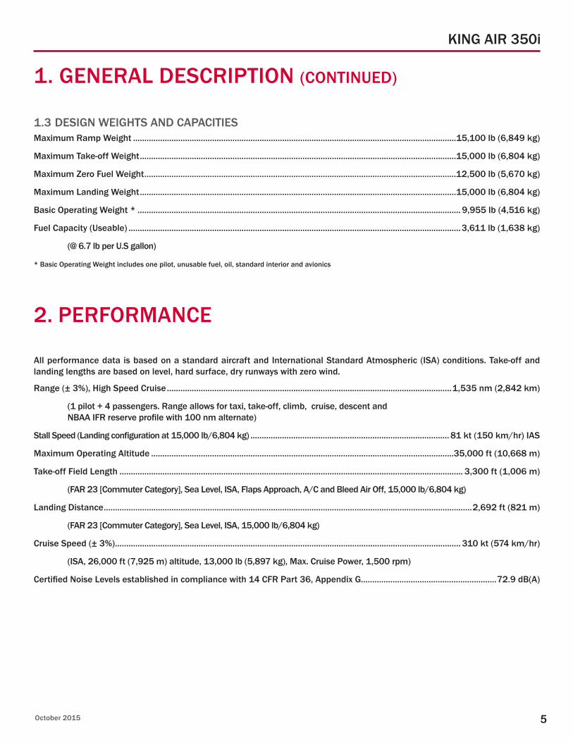
1.3 DESIGN WEIGHTS AND CAPACITIESMaximum Ramp Weight ...............................................................................................................................................15,100 lb (6,849 kg)
Maximum Take-off Weight ............................................................................................................................................15,000 lb (6,804 kg)
Maximum Zero Fuel Weight ..........................................................................................................................................12,500 lb (5,670 kg)
Maximum Landing Weight ............................................................................................................................................15,000 lb (6,804 kg)
Basic Operating Weight * ............................................................................................................................................... 9,955 lb (4,516 kg)
Fuel Capacity (Useable) ...................................................................................................................................................3,611 lb (1,638 kg)
(@ 6.7 lb per U.S gallon)
* Basic Operating Weight includes one pilot, unusable fuel, oil, standard interior and avionics
2. PERFORMANCE
All performance data is based on a standard aircraft and International Standard Atmospheric (ISA) conditions. Take-off and landing lengths are based on level, hard surface, dry runways with zero wind.
Range (± 3%), High Speed Cruise ..............................................................................................................................1,535 nm (2,842 km)
(1 pilot + 4 passengers. Range allows for taxi, take-off, climb, cruise, descent and NBAA IFR reserve profile with 100 nm alternate)
Stall Speed (Landing configuration at 15,000 lb/6,804 kg) ........................................................................................ 81 kt (150 km/hr) IAS
Maximum Operating Altitude ......................................................................................................................................35,000 ft (10,668 m)
Take-off Field Length ........................................................................................................................................................ 3,300 ft (1,006 m)
(FAR 23 [Commuter Category], Sea Level, ISA, Flaps Approach, A/C and Bleed Air Off, 15,000 lb/6,804 kg)
Landing Distance ...................................................................................................................................................................2,692 ft (821 m)
(FAR 23 [Commuter Category], Sea Level, ISA, 15,000 lb/6,804 kg)
Cruise Speed (± 3%) ......................................................................................................................................................... 310 kt (574 km/hr)
(ISA, 26,000 ft (7,925 m) altitude, 13,000 lb (5,897 kg), Max. Cruise Power, 1,500 rpm)
Certified Noise Levels established in compliance with 14 CFR Part 36, Appendix G............................................................72.9 dB(A)

KING AIR 350i
October 20156
3. STRUCTURAL DESIGN CRITERIA
The King Air 350i wing and fuselage are of conventional semi-monocoque construction. It has fully cantilevered wings and a T-tail empennage. Most of the structures are fabricated of high strength aluminum alloy. Steel and other materials are used as needed. The design is based on damage tolerance concepts. The airframe is certified damage tolerant (unlimited life) which ensures continuing structural integrity through an inspection program and appropriate maintenance action. The aircraft structure is divided into three major components, the fuselage, wing and empennage.
Design maneuvering load limits are -1.24 to +3.10 g’s.
At the maximum operating altitude of 35,000 ft (10,668 m), a nominal maximum cabin pressure differential of 6.6 psi provides a 10,400 ft (3,170 m) cabin altitude.
Limit Speeds
VMO (at sea level to 21,000 ft (6,400 m)) ........................................................................................................................263 KIAS (487 km/hr) VMO (21,000 ft (6,400 m) to 35,000 ft (10,668 m)) ........................................................................ 263 to 194 KIAS (487 to 359 km/hr) MMO .........................................................................................................................................................................................................................0.58 M
Flap Extension Speeds
VFE (Approach).........................................................................................................................................................................202 KIAS (374 km/hr) VFE (Full Down) ........................................................................................................................................................................158 KIAS (293 km/hr)
Landing Gear Operating and Extension Speeds
VLO (extension) ........................................................................................................................................................................184 KIAS (341 km/hr) VLO (retraction) ........................................................................................................................................................................166 KIAS (307 km/hr) VLO (emergency operating) ..................................................................................................................................................184 KIAS (341 km/hr)
CG Range
Forward Limit to 11,800 lb (5,352 kg) ...................................................................................................................................................7.8% MAC Forward Limit to 15,000 lb (6,803 kg) ................................................................................................................................................19.3% MAC Aft Limit .......................................................................................................................................................................................................31.7% MAC

KING AIR 350i
October 2015 7
4. FUSELAGE
The fuselage is fabricated of high strength aluminum alloy, with appropriate use of steel and other materials. The structural design is based on damage tolerance (fail-safe) principles using multiple load paths, bonded doublers and small panel sizes on the primary structure.
The multiframe fuselage is shaped to provide optimized cabin room and passenger comfort. A maximum internal cabin width of 4 ft 6 in. (1.37 m) and maximum cabin height of 4 ft 9 in. (1.45 m) is provided.
The fuselage is divided into three subsections; an unpressurized nose section, a pressurized flight deck and cabin section and an unpressurized tail section.
4.1 NOSE SECTIONThe nose section provides the available space for avionics equipment, weather radar antenna, landing lights and nose landing gear. The avionics equipment is located in the upper portion of the nose bay and is accessible through lockable left and right nose access doors. The nose landing gear and landing lights are located in the wheel well in the bottom of the nose section.
4.2 PRESSURIZED CABIN SECTIONThe cockpit and passenger cabin comprise the pressurized portion of the fuselage. The pressure vessel extends from the forward pressure bulkhead to the aft pressure bulkhead and has a maximum operational differential pressure of 6.6 psi. The cabin entry door is located on the left rear side of the fuselage while the left and right forward sides of the fuselage incorporate the emergency exit doors.
4.3 TAIL SECTION The tail section contains space for the oxygen bottle and cockpit voice recorder. An optional flight data recorder may also be located in this area.
4.4 FLIGHT COMPARTMENT WINDOWS The windshields are a glass and acrylic sandwich and are anti-iced using electro-thermal elements between the panes of glass. Rain removal on the ground and during low speed flight is achieved by use of electromechanical windshield wipers.
5. WING
The wing is of semi-monocoque construction incorporating dual spar structures from wing tip to wing tip. The front and rear spars are similar in construction consisting of upper and lower cap extrusions, stiffeners and webs. The inboard section of each spar consists of a combination of channel fittings, assembled back to back, made from 7075 aluminum plate and forging for the front and rear spar fittings. The wings are attached to the wing center section at these fittings using eight bolts. The main landing gear attach fittings are installed on the rear spar. Flaps and ailerons are installed on the wing.
The four segment flaps are attached to the trailing edges of the wing. The flaps are attached to rail assemblies on the inboard edge of the wing. The flaps consist of a front spar, a rear spar, ribs, side plates, skins and a fairing.
The wing flaps are electrically operated using an electric flap motor. A safety mechanism is provided to disconnect power to the electric flap motor if an asymmetrical condition occurs. The flap system is operated by a flap control lever located on the center pedestal. The flap control lever has three positions: Up, Approach and Down.
Winglets of composite construction are fitted at the wing tips to enhance performance.
KING AIR 350i
October 20158
6. EMPENNAGE
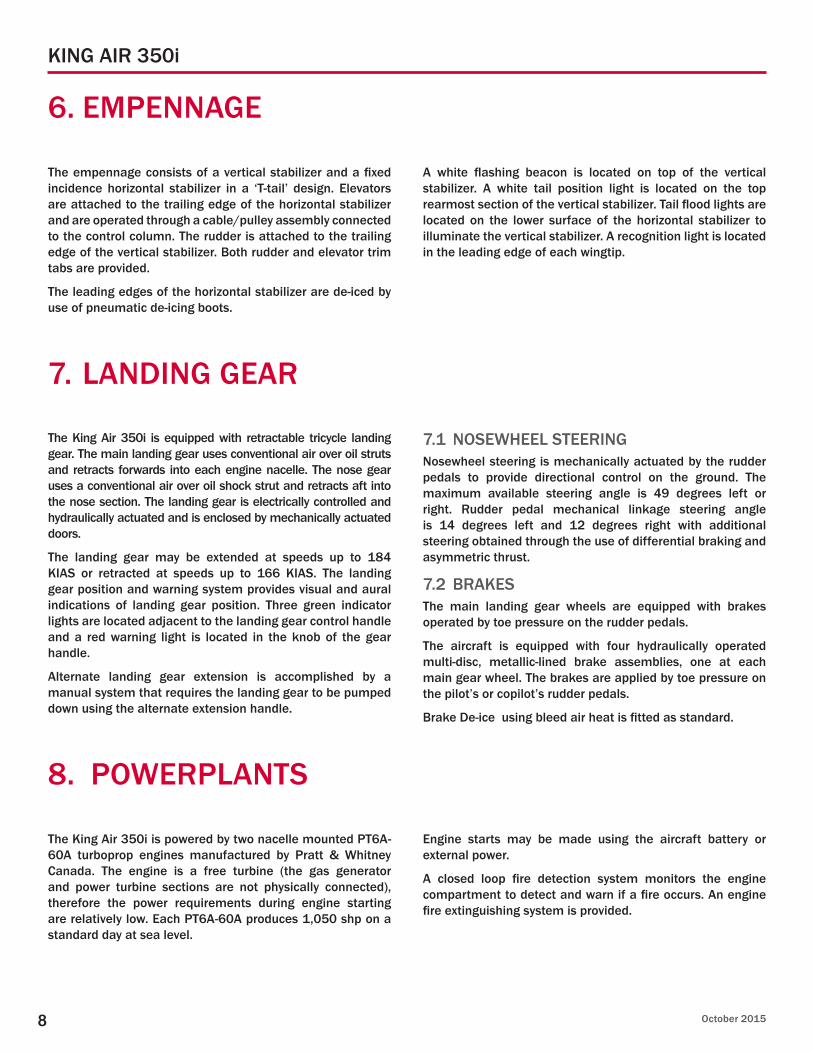
The empennage consists of a vertical stabilizer and a fixed incidence horizontal stabilizer in a ‘T-tail’ design. Elevators are attached to the trailing edge of the horizontal stabilizer and are operated through a cable/pulley assembly connected to the control column. The rudder is attached to the trailing edge of the vertical stabilizer. Both rudder and elevator trim tabs are provided.
The leading edges of the horizontal stabilizer are de-iced by use of pneumatic de-icing boots.
A white flashing beacon is located on top of the vertical stabilizer. A white tail position light is located on the top rearmost section of the vertical stabilizer. Tail flood lights are located on the lower surface of the horizontal stabilizer to illuminate the vertical stabilizer. A recognition light is located in the leading edge of each wingtip.
7. LANDING GEAR
The King Air 350i is equipped with retractable tricycle landing gear. The main landing gear uses conventional air over oil struts and retracts forwards into each engine nacelle. The nose gear uses a conventional air over oil shock strut and retracts aft into the nose section. The landing gear is electrically controlled and hydraulically actuated and is enclosed by mechanically actuated doors.
The landing gear may be extended at speeds up to 184 KIAS or retracted at speeds up to 166 KIAS. The landing gear position and warning system provides visual and aural indications of landing gear position. Three green indicator lights are located adjacent to the landing gear control handle and a red warning light is located in the knob of the gear handle.
Alternate landing gear extension is accomplished by a manual system that requires the landing gear to be pumped down using the alternate extension handle.
7.1 NOSEWHEEL STEERINGNosewheel steering is mechanically actuated by the rudder pedals to provide directional control on the ground. The maximum available steering angle is 49 degrees left or right. Rudder pedal mechanical linkage steering angle is 14 degrees left and 12 degrees right with additional steering obtained through the use of differential braking and asymmetric thrust.
7.2 BRAKESThe main landing gear wheels are equipped with brakes operated by toe pressure on the rudder pedals.
The aircraft is equipped with four hydraulically operated multi-disc, metallic-lined brake assemblies, one at each main gear wheel. The brakes are applied by toe pressure on the pilot’s or copilot’s rudder pedals.
Brake De-ice using bleed air heat is fitted as standard.
8. POWERPLANTS
The King Air 350i is powered by two nacelle mounted PT6A-60A turboprop engines manufactured by Pratt & Whitney Canada. The engine is a free turbine (the gas generator and power turbine sections are not physically connected), therefore the power requirements during engine starting are relatively low. Each PT6A-60A produces 1,050 shp on a standard day at sea level.
Engine starts may be made using the aircraft battery or external power.
A closed loop fire detection system monitors the engine compartment to detect and warn if a fire occurs. An engine fire extinguishing system is provided.

KING AIR 350i
October 2015 9
8.1 PROPULSION SYSTEM CONTROLSThe propulsion system is operated by three sets of controls: the power levers, propeller levers, and condition levers. The power levers serve to control engine power. The condition levers control the flow of fuel at the fuel control outlet and select fuel cutoff, low idle, and high idle functions. The propeller levers are operated conventionally and control the constant speed propellers through the primary governor.
8.2 POWER LEVERSThe power levers provide control of engine power from idle through takeoff power by operation of the gas generator (N1) governor in the fuel control unit. Increasing N1 rpm results in increased engine power.
8.3 PROPELLER LEVERSEach propeller lever adjusts the propeller governor, which results in an increase or decrease of propeller rpm. For propeller feathering, each propeller lever releases high pressure oil from the propeller allowing counterweights and feathering spring to change the pitch. Detents at the rear of lever travel prevent inadvertent movement into the feathering range. In flight, the operating range is 1,450 to 1,700 rpm.
8.4 CONDITION LEVERSThe condition levers have three positions: FUEL CUTOFF, LOW IDLE and HIGH IDLE. Each lever controls the fuel cutoff function of the fuel control unit and limits idle speed at 62% N1 minimum for low idle, and 70% N1 minimum for high idle.
8. POWERPLANTS (CONTINUED)
9. PROPELLERS
Each engine is equipped with a conventional Hartzell 105-inch diameter four blade, full feathering, constant speed, counter-weighted, reversing, variable pitch propeller mounted on the output shaft of the reduction gearbox. The propeller pitch and speed are controlled by engine oil pressure, through single action, engine driven governors. Centrifugal counterweights, assisted by a feathering spring, move the blades toward the low rpm (high pitch) position and into the feathered position. Governor boosted engine oil pressure moves the propeller to the high rpm (low pitch) hydraulic stop and reverse position. The propellers have no low rpm (high pitch) stops; this allows the blades to feather after engine shutdown.
Propeller tie-down boots are provided for use on the moored aircraft to prevent windmilling at zero oil pressure.
9.1 PROPELLER AUTOFEATHERWith the autofeather system armed, in the unlikely event of an engine failure during takeoff, the propeller on that engine will automatically feather.
9.2 SYNCHROPHASERThe King Air 350i’s synchrophaser system not only synchronizes propeller RPM, but also phases blade positions so that right and left propeller blades do not pass by the fuselage at the same time. This prevents the beating type noise sometimes present in non-phased twin engine aircraft. This system is displayed on the Multi-Function Display (MFD).
10. SYSTEMS
10.1 FLIGHT CONTROLSDual flight controls are provided. The primary control system is of conventional design and is manually operated through control cables, push-pull rods and mechanical linkages providing pitch, roll and yaw. Pitch attitude of the aircraft is controlled by the elevators. Roll is controlled through the ailerons. Yaw control is accomplished by use of the rudder.
The secondary control system provides manual and electrical trim for the pitch system, roll trim from the manually operated roll trim surfaces and yaw trim from the manually operated rudder trim surface.
A rudder boost system is installed and is armed by setting the pedestal mounted control switch to the Rudder Boost position. The system senses engine torque from both engines.

KING AIR 350i
October 201510
10. SYSTEMS (CONTINUED)
When the difference in torque exceeds a preset level, the electric servo is activated and deflects the rudder, which assists pilot effort.
Four flaps are mounted on the wings. The flaps move along tracks, actuated by the drive mechanism on the wing rear spar. The wing flaps are electrically actuated and are interconnected by a safety system to ensure symmetrical operation. The flap system is controlled by a flap control lever located on the center pedestal.
10.2 FUEL SYSTEMThe King Air 350i features a conventional, large capacity fuel system requiring minimum management. Fuel management is automatic in normal operation. The fuel system provides an independent fuel supply for each engine and is designed to operate at an altitude up to 35,000 ft within a temperature range of -40°C to +50°C on fuels Jet A, Jet A-1, Jet B, JP-4, JP-5, JP-8 or Chinese No. 3 Jet Fuel. All components in the fuel system are compatible with all fuels approved for the PT6A-60A engine.
The fuel system consists of two separate systems connected by a valve-controlled crossfeed line. The fuel system for each engine is further divided into a main and auxiliary fuel system. The main system consists of a nacelle tank, two wing leading edge tanks, two box section bladder tanks, and an integral (wet cell) tank, all interconnected to flow in to the nacelle tank by gravity. The tanks are filled from the filler near each wingtip.
The auxiliary fuel system consists of a center section tank with its own filler opening, and an automatic fuel transfer system to transfer the fuel into the main fuel system. When the auxiliary tanks are filled, they will be used first.
The engine driven fuel pump (high pressure) is mounted on the accessory case in conjunction with the fuel control unit. The primary boost pump (low pressure) is also engine driven.
10.3 HYDRAULIC SYSTEMThe hydraulic system is powered by an electric motor-driven pump and provides hydraulic pressure for landing gear retraction and extension.
10.4 ELECTRICAL SYSTEMElectrical power to the aircraft is provided by two 28V DC, 300 ampere each engine driven starter-generators. A 24 volt, 42 ampere-hour lead acid battery supplies electrical power for engine starting and emergency requirements. A 28V DC external power receptacle located under the right wing outboard of the nacelle is provided for connection of an external power unit.
Power from these sources is distributed through the DC electrical power distribution system, which provides power to the individual electrical loads through a multi-bus system. Each power source is electrically connected to the distribution system through relays and line contactors.
A 1,000 volt-ampere inverter located in the center fuselage under the floor provides 115 volt 60 Hz AC power to a maximum of six electrical outlets located in the cabin and one outlet in the cockpit.
10.5 PRESSURIZATION AND ENVIRONMENTAL SYSTEMThe pressurization and environmental systems utilize engine bleed air to pressurize and heat the cabin and de-fog the cabin windows. During normal operation, most functions are automatic. The only manual adjustments required are for individual comfort, such as cabin altitude and cabin rate of climb.
The cabin is pressurized by the flow of air from the cockpit and cabin air outlets. The system uses a variable isobaric controller to drive an outflow valve through a pneumatic relay. Both the outflow and safety valves open automatically at max differential pressure to protect the cabin from overpressure.
Cabin air distribution lines are composed of cold air ducts and warm air ducts. Recycled and/or air-conditioned air is delivered to the cockpit and cabin overhead eyeball outlets and the cockpit glareshield. Warm air is delivered through the cabin and cockpit floor outlets.
If additional cooling power is needed, some air-conditioned air will be diverted to flow out the lower cabin outlets by the temperature controller.
The temperature control system is a digital control unit that automatically regulates the temperature of air delivered to the cabin and the cockpit.
The automatic electronic temperature control for both heating and cooling keeps the cabin and cockpit at a constant temperature during climbs and descent. Individual temperature controls for cabin and cockpit, which are located in the cockpit, provides the ability to regulate temperatures in both areas.

KING AIR 350i
October 2015 11
10. SYSTEMS (CONTINUED)
10.6 OXYGEN SYSTEMThe 115 cubic foot oxygen system provides adequate oxygen flow for crew and passengers for a cabin pressure altitude of up to 35,000 ft. The system consists of an oxygen cylinder-regulator assembly mounted in the tail section.
The crew is provided with quick-donning oxygen masks. Oxygen supplies for passengers are provided through drop down masks that are delivered automatically if the cabin altitude rises above 12,500 ft.
10.7 ICE AND RAIN PROTECTION SYSTEMEngine exhaust heat is utilized for heating the engine air inlet lips. Anti-ice protection of the wing and horizontal stabilizer leading edges is provided through engine bleed air driven pneumatic boots. The windshield de-fogging system uses air supplied by the air conditioning system. The windshield, pitot mast, fuel vent, propellers and stall warning vane are electrically heated.
An oil to fuel heat exchanger, located on the engine accessory case, operates continuously and automatically to heat the fuel sufficiently to prevent ice from collecting in the fuel control unit.
Rain removal is achieved by use of a surface seal application. A two speed electromechanical windshield wiper system is also provided for rain removal on the ground and during slow speed flight operations.
10.8 PROTECTIVE COVERINGS3M protective tape is installed on the leading edge of the vertical stabilizer, both tips of the horizontal stabilizers and wings, both wing tip light glareshields, both wing wraparound fairings, and the air conditioner intake. A 3M protective boot is installed on the radome and the vertical stabilizer bullet. Akzo Nobel Aerospace Coatings protective coating is applied inboard and outboard of the engine nacelles on the wing leading edge. An additional layer of sealant is applied around the exterior of the windshield, both heated engine inlets and all windows (excluding the storm windows).

KING AIR 350i
October 201512
11. AVIONICS
FIGURE 2 - KING AIR 350i INSTRUMENT PANEL

KING AIR 350i
October 2015 13
11.1 GENERALThe King Air 350i is certified for single or two pilot operation. All the controls and switches are laid out for accessibility to either pilot. Circuit breakers are located on the pilot’s and copilot’s sidewall and are clearly marked to denote the related electrical bus from which power is provided.
An overhead light control panel, located between the two pilots, contains all the instrument panel light and dimmer switches. A second overhead panel contains generator load monitoring gauges and emergency instrument light controls.
11.2 AVIONICSThe standard flight instrument installation in the King Air 350i is the Rockwell Collins Pro Line Fusion integrated avionics system. The system features three 14.1 inch wide Electronic Flight Instrumentation System (EFIS) Adaptive Flight Displays featuring touchscreen operation.
Features include:
• Synthetic Vision,
• Graphical Flight Planning,
• Integrated charts and enhanced maps,
• Engine Indicating and Crew Alerting System (EICAS)
• Air Data System (ADS)
• Attitude Heading and Reference System (AHRS)
• Automatic Flight Guidance System (AFGS)
• Flight Management System (FMS)
• Weather Radar System (WXR)
• Dual navigation and communication radios.
A. FLIGHT DISPLAY SYSTEMThe Rockwell Collins Electronic Flight Instrumentation System (EFIS) consists of an two touchscreen-enabled AFD-3700 Primary Flight Display (PFD) on the pilot’s and copilot’s panels and a touchscreen-enabled AFD-3700 Multi-Function Display (MFD) located in the center of the panel. Each display includes molded finger grips and may be operated with gloves. Each display is capable of being configured to display information in full screen, half screen and quarter screen windows.
The PFD includes primary attitude, heading, altitude, airspeed, navigation, flight guidance and pilot selectable formats.
The MFD provides display of engine indication, crew alerting messages and pilot selectable formats including maps, charts, weather, navigation data, maintenance information and checklist.
The primary and multi-function displays incorporate touchscreen technology to allow for interactive control of display functions.
Synthetic vision is included as standard and uses a terrain database and current position information to generate a virtual landscape image for the PFD background. The synthetic vision system will also display the origin, destination and alternate airports that have been entered into the flight plan. The image replaces the normal sky/ground depiction that is part of the ADI. The synthetic image dynamically changes, giving the pilot better situational awareness of the surrounding terrain and obstacles, and the airports and runways in the flight plan.
The EFIS displays are also capable of displaying the Rockwell Collins TCAS II and ACSS TAWS+ information.
For the Rockwell Collins enhanced map overlays and Rockwell Collins navigational database a one year subscription service is provided for a customer’s home region beginning on the date of aircraft acceptance. For the Jeppesen Electronic Charts, a one year subscription service is provided for individuals and civilian entities only. Note: All military or government agencies will be able to obtain annual subscription services directly from Jeppesen at additional cost.
B. COCKPIT CONTROLSIn addition to touchscreen technology on the primary and multi-function displays, the system also includes dedicated cockpit controls for flight control mode selection, cursor manipulation, barometric setting, radar tilt control and alphanumeric entry. Control panels include a glareshield mounted Flight Control Panel, four single-knob controls for barometric setting and radar tilt (two per pilot position), two pedestal mounted Cursor Control Panels and one Multifunction Keypad Panel for entering data into the flight management and other systems.
Each Cursor Control Panel (CCP) features a three function concentric knob that acts as a free-floating cursor control, a tabbing cursor movement device and display data selection knob. It also contains controls for selecting COM 1 and 2, one-button traffic display selection and a radio tuning knob. The CCP is also used to position the cursor on the either the PFD or the MFD.
11. AVIONICS (CONTINUED)

KING AIR 350i
October 201514
11. AVIONICS (CONTINUED)
The Multifunction Keypad (MKP) features a QWERTY keypad with an numeric keypad and several shortcut keys to simplify data entry. One-button push accessibility is available for the selection of the following windows on each display:
• Map display in full, half or quarter screen window
• Charts
• Crew Alerting System (CAS)
• Flight Management System planning (FMS)
• Direct-To
• Departure and Arrival procedure dialogue box selection
• Checklists
• Aircraft System information- synoptics for engine start
• Radio tuning window or Datalink messaging window
• QIK Tune key for parsing radio frequencies
• Memory key for selecting any of six pre-programmed flight deck display window configurations. This will place all three flight deck displays in a pre-determined configuration of data windows.
C. INTEGRATED CHARTSThe center display has built-in, geo-referenced electronic navigation charts that display “own-ship” aircraft position for enhanced situational awareness during approaches. Airport diagams can be displayed after landing to make surface navigation easier. Displaying charts on each PFD is an optional feature.
D. ENGINE INDICATING AND CREW ALERTING SYSTEM (EICAS)The Engine Indicating and Crew Alerting System provides electronic displays primary engine operating information and provides alerts and display changes when operating outside limits. Crew alerts include caution, warning, advisory and status annunciators on the MFD.
E. ELECTRONIC CHECKLISTSElectronic checklists are provided to enable the pilot to systematically perform both normal and abnormal checklist tasks. Checklists can be displayed, indexed and selected by using the menu system controlled with the Cursor Control Device or by touching the screen.
F. FLIGHT GUIDANCE SYSTEM (FGS)The Rockwell Collins FGC-3000 Automatic Flight Guidance System (AFGS) provides an integrated fail-passive three-axis autopilot with yaw damper, flight guidance operation and automatic pitch trim. The AFGS consists of two identical flight guidance computers, three primary servos and a Flight Guidance Panel (FGP).
Two FGC-3000 Flight Guidance Computers (FGCs) provide independent flight guidance computation and operate together to provide 3-axis autopilot, pitch trim and rudder boost functions.
Pilot operation is accomplished through a single integrated FGP-3000 control panel. This panel contains controls for Flight Guidance modes and operation, autopilot operation and yaw damp operation.
G. AIR DATA SYSTEM (ADS)The dual Rockwell Collins ADC-3000 Digital Air Data Computers supply digital output signals to the displays (airspeed and altitude), IAPS, AHRS, transponders, Flight Guidance System and autopilot. The system is RVSM capable.
H. ATTITUDE HEADING SYSTEM (AHRS)The dual Rockwell Collins AHC-3000 AHRS provides precision attitude body rates and three-axis linear acceleration data necessary for precision flight path control. The AHRS system provides the basic attitude and heading data displayed on the Primary Flight Display (PFD).
I. FLIGHT MANAGEMENT SYSTEM (FMS)The dual Rockwell Collins Flight Management System is a multi-sensor, position blending, navigation/flight management system that derives precise aircraft position. The system is capable of using VOR/DME, DME/DME and GPS signals to determine position and provides RNP 0.3 accuracy and WAAS/LPV approach capability and Radius-to-fix (RF) legs.
The flight crew can use the Cursor Control Panels, multifunction Keypad Panel or touchscreen control to enter data and interface with the flight management system. Graphical Flight Planning simplifies navigation tasks and increases situational awareness through touch-interactive graphical maps with high-resolution terrain, weather overlays, obstacles and geopolitical boundaries.

KING AIR 350i
October 2015 15
11. AVIONICS (CONTINUED)
J. RADIO SYSTEM The avionics package includes the following radio systems:
• Dual Rockwell Collins VHF-4000 VHF Communication Transceivers that operate in the 118.00 to 136.975 MHz frequency range in 8.33 KHz spacing increments. Tuning through multifunction keypad or touchscreen. The VHF-4000 radios meet ICAO Annex 10 FM Immunity requirements.
• Single Rockwell Collins NAV-4000 Navigation Receiver integrates VOR/LOC/Glideslope/ADF/Marker Beacon functions. Tuning through multifunction keypad or touchscreen. The ADF has a frequency reception range from 190 to 1799.5 and 2179 to 2185 KHz (selectable in 500 Hz increments).
• Single Rockwell Collins NAV-4500 Navigation Receiver integrates VOR/LOC/Glideslope/Marker Beacon functions. Tuning through multifunction keypad or touchscreen. The NAV-4000 series radios meet ICAO Annex 10 FM Immunity requirements.
• Dual Rockwell Collins TDR-94D solid-state, airborne, Mode S air traffic control Transponders with Flight ID and ADS-B Out compliant with the DO-260B standard.
• Single Rockwell Collins DME-4000 Distance Measuring Equipment (DME). This unit is able to simultaneously interrogate three DME stations.
• Single Rockwell Collins ALT-4000 Radio Altimeter. The ALT-4000 is a solid-state radio altimeter that provides altitude information from 0 to 2,500 feet (762 m) AGL.
• Single GPS-4000S Global Positioning System (GPS). The GPS-4000S sensor processes the transmissions of up to twelve GPS satellites simultaneously and calculates navigation solutions based on information from all satellites in view. The computed position, velocity and time are input to the Flight Management System that integrates this data into the flight plan based navigation solution.
K. AUDIO SYSTEMThe dB Systems Model 700 amplifiers with Model 804 (pilot) / Model 805 (copilot) Audio Panels feature dual auto COMM and audio switches, crew interphone, dual cockpit speakers, microphone key button on pilot and copilot control wheels, dual hand-held microphones, dual boom microphone headsets, voice and ident filters.
L. WEATHER RADAR SYSTEM (WXR)The Rockwell Collins TWR-850 Weather Radar is a four color, 6 range weather radar designed to interface with the EFIS, Primary Flight Display (PFD) and Multi-Function Display (MFD). The radar features ± 15 degrees of antenna tilt (12 in. diameter antenna), 14 scans of 120 degrees per minute. Color weather depictions clearly identify the intensity and level of targets in any mode of operation.
M. ONBOARD MAINTENANCE SYSTEM (OMS)The Onboard Maintenance System provides data to the flight line technician to be used for aircraft maintenence. The system collects data from the various components of the avionic and aircraft systems and provides fault detection and analysis as well as identification, recording and display of maintenance information on the Multifunction Display.
N. TRAFFIC ALERT AND COLLISION AVOIDANCE (TCAS II)A Rockwell Collins TCAS-4000 TCAS II system with version 7.1 software is installed as standard. The TCAS interrogates transponders of surrounding aircraft and displays the relative position of the aircraft targets on either MFD. The system provides aural and visual Traffic Advisories (TAs) and Resolution Advisories (RAs).
For RAs, the system displays required vertical evasive maneuvers in the form of green arcs on the vertical speed indicator of both PFDs. Controls for the system are integrated in the MFDs and CDUs. The TCAS-4000 system complies with Change 7 and European ACAS requirements.
O. TERRAIN AWARENESS AND WARNING SYSTEM (TAWS+)The ACSS TAWS+ system provides a Terrain Awareness and Warning System Class A (TAWS) displayed on the MFD in normal mode or PFD in reversionary mode.
P. ELECTRONIC STANDBY INSTRUMENT SYSTEM (ESIS)A L3 Communications GH-3900 ESIS provides back-up display of attitude, heading, airspeed, altitude and nav with back-up battery.

KING AIR 350i
October 201516
Q. ADDITIONAL AVIONICS INCLUDE:• Cabin Paging System with five speakers.
• Solid-State Cockpit Voice Recorder (SSCVR) L3 Communications FA2100 with remote area microphone (120 minutes recording time).
11. AVIONICS (CONTINUED)
• Emergency Locator Transmitter (ELT) – Artex C406-N ELT with switch control in cockpit.
• Magnetic compass
12. INTERIOR
The King Air 350i offers a large and spacious 355 cubic foot (10.05 cu. m) cabin providing comfortable passenger seating. The cabin dimension from the floor to the ceiling is 4 ft 9 in. (1.45 m). Cabin width is 4 ft 6 in. (1.37 m). The length of the cabin is 19 ft 6 in. (5.94 m). At the rear of the passenger compartment is a private lavatory.
The cabin features LED lighting throughout including variable intensity indirect downwash lighting, reading and table lighting and floor level accent lighting.
The passenger seats are large and luxurious. Each seat is equipped with fore and aft travel, swivel and reclining capability. An armrest that can be raised or lowered is built into the inboard side of the chair. The seat controls are located in the armrest. New tailoring provides additional lumbar support and integrated headrest.
Cabinetry in the standard aircraft consists of a forward refreshment cabinet on the left side of the cabin. Features include insulated carafe, ice container, trash container, chilled wine bottle storage and customizable storage inserts.
Lower profile ‘pyramid’ cabinets are located on the forward right side, between the center seats and aft right side.
Executive writing tables are provided in the club seating areas on both the left and right side of the cabin and stow in the sidewall panels.
Each window includes electronically dimmable window darkeners.
In the lavatory area, a belted passenger seat is provided. The seat is certified for take-off and landing. The private lavatory features a flushing recirculating chemical toilet and relief tube. Seat cushion and seat back are tailored to suit aircraft interior.
12.1 INFLIGHT WI-FI CONNECTIVITYInstalled system will depend on intended usage. Customers can select from either:
US DOMESTIC• Gogo ATG 5000 Transceiver with Gogo Biz Service
Provides a broadband data connection operational above 10,000 feet above ground level (AGL) in the U.S. and portions of Canada and Alaska, providing a mobile broadband experience. (Requires Gogo Biz Data Subscription Service).
The system offers wireless internet access for multiple users in the aircraft cabin and cockpit and is compatible with IEEE 802.11 wireless-equipped personal devices such as laptops, tablets, and handheld devices. (Average connection speeds vary depending upon number of users and other factors).
Or:
INTERNATIONAL• Gogo Aviator 200 SwiftBroadband Satellite Service
The Aviator 200 system uses Inmarsat’s I-4 geostationary satellites, which offer service coverage in multiple regions around the world. (Gogo Business Aviation SwiftBroadband service charges apply).
The system offers wireless internet access for multiple users in the aircraft cabin and cockpit and is compatible with IEEE 802.11 wireless-equipped personal devices such as laptops, tablets, and handheld devices. The system is operational both in flight and on the ground (when a clear line of sight to the nearest satellite is available) and provides customers with connectivity speeds up to a maximum of 200 kbps. (Average connection speeds vary depending upon number of users and other factors).

KING AIR 350i
October 2015 17
FIGURE 3 - KING AIR 350i STANDARD FLOORPLAN
12. INTERIOR (CONTINUED)
19 ft. 6 in (5.94 m)
4 ft 6 in (1.37 m)
4 ft. 9 in (1.45 m)

KING AIR 350i
October 201518
12.2 “QUIET CABIN” NOISE CONTROLThe King Air 350i features several dynamic vibration absorbers mounted throughout the cabin and flight deck, with each one specifically tuned to attenuate tonal noise and vibration from the propellers. Skin-mounted constrained layer damping panels provide both damping and stiffening effects, thus yielding significant reduction of fuselage vibration induced noise. Phase adjustment between the propellers results in effective noise cancellation in the cabin.
12. INTERIOR (CONTINUED)
In addition, three inches of bagged fiberglass insulation, the use of sound-deadening trim panels and a vibration-isolated interior design creates one of the most effective acoustic treatments in any business aircraft.
13. BAGGAGE COMPARTMENT
Located at the rear of the cabin close to the main entry door is the baggage compartment. All interior baggage is heated and pressurized and fully accessible in flight. The size of the baggage compartment is 55.3 cubic feet (1.57 cu. m) with a 550 lb. (249 kg) capacity.
14. EXTERIOR
Distinctive exterior styling featuring polyurethane paint is provided.
15. ADDITIONAL EQUIPMENT
• Propeller Slings (2)
• Engine Inlet Plugs (2)
• Bleed Air Plugs (2)
• Fuel Sump Drain Wrench (1)
• Passenger Briefing Cards (8)
• Coat Hangers (8)
• Pitot Tube Covers (2)
• Gust Lock Assembly
• Flight Bag
• Extra Center Aisle Carpet
• MedAire Program
- MedAire First Aid Kit
- MedAire Automated External Defibrillator (AED)
- One year paid subscription to the MedLink Global Response Center.
External Raisbeck nacelle lockers add an additional 16.0 cu. ft. of baggage space, and an additional 600 lb. (272 kg) of baggage capacity.

KING AIR 350i
October 2015 19
16. EMERGENCY EQUIPMENT
• Fire Extinguisher in Cockpit and Cabin
• Crew & Passenger Oxygen
• Dual-cell Life Vests (10)
• Flashlight
17. DOCUMENTATION AND TECH PUBLICATIONS
Publications provided with and considered a part of the Aircraft include:
• Pilot’s Operating Manual/Aircraft Flight Manual
• Aircraft Technical Log, Section 3, Engine (2)
• Pilot’s Checklist
• Aircraft Technical Log, Section 3, Propeller (2)
• Avionics Pilots Guides
• Maintenance Information Sheet
• Flight Log
• Maintenance/Inspection Log
• Supplementary Log
• Beechcraft Corporation Interactive Maintenance Library CD-ROM including the following manuals:
- Component Maintenance Manual
- Wiring Diagram Manual
- Maintenance Manual
- Parts Manual
- Printed Circuit Board Manual
18. MAINTENANCE TRACKING PROGRAM
CAMP Systems maintenance tracking program provides computerized aircraft maintenance tracking with all data being exchanged electronically.
The CAMP Systems program is a full service aviation management system that continually monitors the entire range of aircraft maintenance and inspection requirements and brings them to the attention of the operator as they become due. CAMP Systems maintenance tracking program allows you to accurately track and predict the maintenance requirements of your aircraft.
CAMP Systems provides a dedicated analyst assigned to your aircraft to ensure that your aircraft data is as accurate and complete as possible. This is an aircraft specific program that is tailored to each specific aircraft serial number.
The first year of CAMP Systems service is provided at no charge to Buyers of a new King Air 350i. Subsequent years of CAMP are available through an annual subscription.
This program reflects Beechcraft Corporation’s commitment to provide all King Air 350i operators worldwide with the finest support services available.

KING AIR 350i
October 201520
19. BEECHCRAFT LIMITED WARRANTY
All new King Air 350i aircraft are covered by the following MANUFACTURER’S LIMITED WARRANTY, which gives Buyer specific legal rights. The law of Kansas applies to this warranty. Note: All warranty work must be accomplished by a Beechcraft Authorized Service Center rated to perform maintenance on King Air aircraft. (Ref: CSD-34414 Rev. 07/13).
A. BEECHCRAFT CORPORATION’S (“BEECHCRAFT”) LIMITED WARRANTY1) Subject to the limitations and conditions hereinafter set forth, Beechcraft warrants, at the time of delivery by Beechcraft, each part of the Aircraft structure (fuselage, empennage, wing and control surfaces) to be free from (i) defects in materials or workmanship, and (ii) defects in design that in view of the state-of-the-art as of the date of manufacture should have been foreseen; provided, however, that the defect must be discovered and reported to Beechcraft within sixty (60) months from the date of delivery of the Aircraft to Buyer.
2) Subject to the limitations and conditions hereinafter set forth, Beechcraft warrants, at the time of delivery by Beechcraft, each part of the Aircraft not mentioned in A. (1) above, except avionics and engines (reference paragraphs D and E below), to be free from (i) defects in materials or workmanship, and (ii) defects in design that in view of the state-of-the-art as of the date of manufacture should have been foreseen; provided, however, that the defect must be discovered and reported to Beechcraft within twenty-four (24) months or twelve hundred (1,200) hours of aircraft operation, whichever time period first expires or event first occurs from the date of delivery of the Aircraft to Buyer; provided further, however, that with respect to exterior paint and interior finish items designed, manufactured or installed by Beechcraft the defect must be discovered and reported to Beechcraft within twenty-four (24) months or four hundred (400) hours of aircraft operation, whichever time period first expires or event first occurs; provided further that with respect to maintenance manuals and other technical publications provided with the Aircraft by Beechcraft the defect must be discovered and reported to Beechcraft within the period of the free update subscription also provided with the aircraft for any such manual or publication.
3) Subject further to A. (4) below, the entire extent of Beechcraft’s liability shall be limited to that of either reimbursing Buyer for its costs of purchasing a rebuilt, overhauled or repaired part from either Hawker Beechcraft Parts & Distribution or a properly rated Beechcraft Authorized Service Center or, at Beechcraft’s election, reimbursing Buyer for its costs of having the part repaired at a properly rated Beechcraft Authorized Service Center. If Beechcraft elects
not to repair the part and if neither a rebuilt, overhauled or repaired part is, in Beechcraft’s opinion, timely available then Beechcraft will reimburse Buyer for its costs of purchasing a new part from either Hawker Beechcraft Parts & Distribution or a properly rated Beechcraft Authorized Service Center. The labor necessary to complete a repair or remove from the Aircraft such part or parts and to reinstall in the Aircraft such part or parts, as well as any repair made as the result of improper installations by Beechcraft, shall be covered by this Warranty, provided the work is performed at a properly rated Beechcraft Authorized Service Center. A claim must be submitted within sixty (60) days after the work is performed and the part to be replaced must be returned shipping prepaid to Hawker Beechcraft Parts & Distribution within sixty (60) days after the occurrence of the defect at Buyer’s own expense (including but not limited to, freight, insurance, customs duties, etc.) unless otherwise directed by Beechcraft Warranty. BEECHCRAFT’S LIMITED WARRANTY will apply to any part repaired or replaced by a properly rated Beechcraft Authorized Service Center pursuant to BEECHCRAFT’S LIMITED WARRANTY: however, the applicable warranty for such part repaired or replaced shall be limited to the unexpired portion of BEECHCRAFT’S LIMITED WARRANTY described in A. (1) or A. (2) above, as applicable. In other words, the warranty period of the part repaired or replaced does not start over from the date of reinstallation.
4) This limited warranty is pro-rated for life-limited parts. For Aircraft parts or systems that have life limitations (including replacement or overhaul intervals) established in the airworthiness section of the Beechcraft maintenance manual or in other technical publications including Safety Communiqués and Service Bulletins, Beechcraft’s liability hereunder shall be further limited to the remaining pro-rated life of the defective part, calculated as of the date the defect was discovered and reported to Beechcraft. For example, if a life limited part is found and reported to be defective at 1500 hours of a 2000 hour replacement or overhaul interval (or 750 cycles of a 1000 cycle interval or nine months of a one year age interval), 75% of its life will have been consumed and Beechcraft will provide 25% of the cost for replacing the part. If the part’s life limit is measured by alternative means (such as hours, cycles and/or age), the pro-ration calculation shall be based on the factor nearest to expiring as of the time the defect is discovered and reported. Nothing about this provision shall be construed to extend the total warranty period beyond the applicable time periods stated in A. (1) or A. (2) above. All warranties expire as noted in A. (1) or A. (2) above, regardless of any remaining life limits on parts. All life limited parts replaced during the New Aircraft Warranty are covered only by their own spare parts warranties; if and as applicable and shall have no coverage under this warranty.

KING AIR 350i
October 2015 21
5) Routine services (such as inspections, cleaning, adjustments, etc.) and replacement of items which deteriorate from expected normal wear and tear or exposure (such as paint, upholstery, trim items, bulbs, tires, brakes, hoses, belts, batteries, etc.) are not covered by this LIMITED WARRANTY. Such routine services and replacements required during the course of operation are not considered to be the result of any defect in the Aircraft.
B. LIMITATIONS APPLICABLE TO BEECHCRAFT’S LIMITED WARRANTY 1) Beechcraft will be relieved of all obligations and liability under this Warranty if:
i. The alleged defect in the part is due to expected normal wear and tear (such as that is normally expected to paint, upholstery, trim items, etc.), to environmentally induced corrosion or erosion, to foreign object damage, or to misuse or neglect on the part of someone other than Beechcraft; or
ii. Beechcraft’s and/or Beechcraft’s supplier’s identification mark or name or serial number has been removed from the part in question; or
iii. The Aircraft and/or equipment have not been maintained, operated or stored either in accordance with applicable manuals, communications or other written instructions (including, but not limited to, Mandatory Service Bulletins), of Beechcraft or any manufacturer of the part involved, or in accordance with applicable Federal Aviation Regulations and advisory circulars unless Buyer shows that such maintenance, operation or storage was not a contributory cause of the defect; or
iv. The part or system in question has been modified or altered after delivery other than by the Manufacturer or in accordance with a modification or alteration scheme approved in writing by the Manufacturer. In addition, any part or system of the aircraft affected by a modified or altered part or system will not be covered by Beechcraft’s Limited Warranty; or
v. The Aircraft is used for purposes other than conventional owner/operator usage. Usage not considered conventional owner/operator includes, but is not limited to, scheduled airline operations or military operations.
2) For the purpose of this Warranty, no part of the Aircraft or equipment will be regarded as breaching the LIMITED WARRANTY merely because, subsequent to its delivery, some modification or alteration becomes necessary for product improvements or in order to meet a change in the requirements of any applicable Federal Aviation Regulation.
3) TO THE EXTENT ALLOWED BY APPLICABLE LAW, BUYER WAIVES AS TO BEECHCRAFT AND SELLER ALL OTHER WARRANTIES, WHETHER OF MERCHANTABILITY, FITNESS OR OTHERWISE. THERE ARE NO WARRANTIES WHICH EXTEND BEYOND THE DESCRIPTION ON THE FACE HEREOF.
4) TO THE EXTENT ALLOWED BY APPLICABLE LAW, THE OBLIGATIONS OF BEECHCRAFT SET FORTH HEREIN SHALL BE THE EXCLUSIVE REMEDIES FOR ANY BREACH OF WARRANTY HEREUNDER, AND, TO THE SAME EXTENT, NEITHER BEECHCRAFT NOR SELLER SHALL BE LIABLE FOR ANY INCIDENTAL, INDIRECT, SPECIAL, CONSEQUENTIAL, MULTIPLE OR PUNITIVE DAMAGES, INCLUDING, WITHOUT LIMITATION, ANY DAMAGES FOR DIMINUTION OF MARKET VALUE, LOSS OF USE OR LOSS OF PROFITS, OR ANY DAMAGES TO THE AIRCRAFT CLAIMED BY BUYER OR ANY OTHER PERSON OR ENTITY UPON THE THEORIES OF NEGLIGENCE OR STRICT LIABILITY IN TORT.
5) ANY ACTION BY BUYER FOR BREACH OF THIS WARRANTY BE EITHER BEECHCRAFT OR SELLER MUST BE COMMENCED WITHIN ONE (1) YEAR AFTER THE CAUSE OF ACTION ACCRUES. THE CAUSE OF ACTION ACCRUES WHEN THE BUYER FIRST LEARNS THAT THE WARRANTY HAS BEEN BREACHED.
C. TRANSFER OF WARRANTYIn the event the Aircraft is resold to another person, firm or entity prior to the expiration of the Limited Warranty described in paragraph A above, any remaining term of that Limited Warranty is automatically transferred to subsequent purchasers of the Aircraft, but subject to the limitations described in paragraph B above.
D. AVIONICS EQUIPMENT WARRANTED BY APPLICABLE MANUFACTURERS.Factory installed standard avionics equipment is warranted by the respective manufacturers for varying periods of time. Details of these programs are available from the applicable manufacturer. The majority, but not all, of the Standard Equipment Avionics Suite is manufactured by Rockwell Collins. The following is a summary of the Limited Warranty provided by Rockwell Collins Commercial Systems Division of Rockwell International with respect to Rockwell Collins Pro Line Fusion avionics suite:
STANDARD AVIONICS WARRANTED BY ROCKWELL COLLINS
A. Rockwell Collins agrees to repair or replace at its discretion, without charge, any such equipment, which is defective as to design, workmanship or material, and which is returned to Rockwell Collins at its factory, transportation prepaid, provided:
(i) Notice of the claimed defect is given Rockwell Collins within five (5) years from date of delivery and equipment is returned in accordance with Rockwell Collins instructions.
(ii) Such equipment shall not be deemed to be defective, if, due to exposure to any condition in excess of those published in the product specification, it shall fail to operate in a normal manner.
19. BEECHCRAFT LIMITED WARRANTY (CONTINUED)
KING AIR 350i
October 201522
(iii) Rockwell Collins’ obligations with respect to such equipment are conditioned upon the proper installation and operation of such equipment by Buyer in accordance with Rockwell Collins written directions.
(iv) This warranty shall be void if such equipment is altered or repair is attempted or made by other than Rockwell Collins or Rockwell Collins’ authorized service center.
B. Rockwell Collins warrants that any software delivered hereunder, either embedded in equipment described herein or specifically designed for use in or with such equipment, will substantially provide the functions set forth in the applicable specification (or absent a specification, as described in the applicable Service Bulletin). Rockwell Collins will, at its option, without charge, revise or replace such nonconforming software provided:
(i) Notice of the claimed defect is given Rockwell Collins within twelve (12) months from the date of delivery.
(ii) Software shall not be deemed to be defective if the software or the host medium is exposed to any computer virus or to any conditions in excess of those published in the applicable specification(s).
(iii) Rockwell Collins’ obligations are conditioned upon the proper installation and operation of software and the host medium in accordance with Rockwell Collins’ written instructions.
(iv) This warranty shall be void if such software (or its host medium) is altered (or alterations are attempted) by other than Rockwell Collins or Rockwell Collins’ authorized service center.
NO OTHER WARRANTIES, EXPRESSED, IMPLIED, OR STATUTORY, INCLUDING ANY IMPLIED WARRANTY OF MERCHANTABILITY OR OF FITNESS FOR A PARTICULAR PURPOSE SHALL BE APPLICABLE TO ANY EQUIPMENT SOLD OR SOFTWARE DELIVERED HEREUNDER, AND THE FOREGOING SHALL CONSTITUTE THE BUYER’S SOLE RIGHT AND REMEDY.
Note: For avionics installed in all military use airplanes, Rockwell Collins warranty is two (2) years (24 months) from date of delivery of the airplane.
E. ENGINES WARRANTED BY PRATT & WHITNEY CANADA.Engines are warranted by their manufacturer, Pratt & Whitney Canada. Details of the engine warranty is available from Pratt & Whitney Canada. An outline of that engine warranty is as follows:
WARRANTY FOR NEW ENGINES.Pratt and Whitney Canada (P&WC) warrants that at the time of delivery, all parts of a new engine comply with the relevant specification and are free from defects in material and workmanship and that the engine shall be free from defects in design, having regard to the state of the art at the time of said design and the requirements for the engine as installed on the aircraft.
This warranty shall take effect immediately upon acceptance of the engine by the Buyer, either installed in an aircraft or delivered as a spare, and shall remain in force until the expiration of five (5) years from delivery to the first operator or the completion of 2,500 operating hours, whichever occurs first. This warranty is transferable to subsequent operators.
COVERAGE.During the warranty period, P&WC will repair or replace any parts found to be defective (including resultant damage to the engine) during the warranty period. Such replacement may, at P&WC’s option, be made with new parts or serviceable parts.
P&WC will pay reasonable troubleshooting labor, engine removal and reinstallation costs and transportation costs (excluding insurance, duties and taxes) to and from a repair facility designated by P&WC Warranty Administration.
When a rental engine is required to support an engine removal covered by the terms of this warranty, P&WC will provide a special warranty engine rental rate based on the reasonably expected engine maintenance cost for the operator’s mission profile.
The operator is responsible for the costs of scheduled maintenance during the warranty period, including but not limited to, routine line maintenance and adjustments, hot section inspection and refurbishment, and engine overhaul. Removal of a part from service because of hourly, cyclic, normal wear and tear or other limitations on its continued use specified in P&WC maintenance or service documents, will not constitute a defect under this warranty, but may be supported on a pro rata (pay for use) basis under the Primary Parts Service Policy.
Notice of a warranty defect must be provided to P&WC within thirty (30) days of the occurrence, and P&WC reserves the right to refuse any warranty claim received more than 180 days after removal from operation of any engine or engine part.
APPLICATION.This Warranty For New Engines applies only to engines operated in non-military aircraft used for commercial, corporate, or private transportation service.
19. BEECHCRAFT LIMITED WARRANTY (CONTINUED)
KING AIR 350i
October 2015 23
OPERATOR’S RESPONSIBILITIES.The operator is responsible for operating and maintaining the engine, and the cost thereof, in accordance with applicable manuals and recommendations. This includes, but is not limited to, routine line maintenance and adjustments, hot section inspection and refurbishment and engine overhauls described in P&WC manuals and required by regulatory authorities. All warranty repairs must be carried out at a facility designated by P&WC warranty administration. P&WC shall not be responsible for defects or damages, and the costs thereof, resulting from improper use or maintenance, normal wear and tear, accident, foreign object damage (FOD), erosion, corrosion, sulphidation or any other cause beyond the control of P&WC.
LIMITATIONS.This is the only warranty applicable to the engine and is given and accepted in place of all other warranties or remedies, express or implied, including without limitation any warranties as to MERCHANTIBILITY or fitness for purpose. In no event shall P&WC be responsible for incidental or consequential damages.
OTHER TERMS AND CONDITIONS APPLY TO THE WARRANTY. A COMPLETE COPY OF THE WARRANTY FOR NEW ENGINES MAY BE OBTAINED FROM P&WC PARTS AND COMMERCIAL SERVICES ON REQUEST.
F. WARRANTY BY HARTZELL PROPELLER INC.Propellers are warranted by their manufacturer, Hartzell Propeller, Inc. Details of the propeller warranty is available from Hartzell Propeller Inc. An outline of that engine warranty is as follows:
WARRANTY FOR NEW PROPELLERSHartzell Propeller Inc. warrants that at the time of delivery, all parts of the propeller conform to and meet the requirements of the specifications and are free from defects in material and workmanship.
This warranty shall take effect immediately upon acceptance of the aircraft and shall remain in force until the expiration of three (3) years from delivery to the first operator or the completion of 2,000 operating hours, whichever occurs first.
This warranty does not apply to normal wear and tear, components reaching the end of their useful lives, failures caused by accident, abuse, misuse, or environmental conditions, and failure to maintain, use or store in accordance with instructions provided.
20. CREW TRAINING AGREEMENT
CREW TRAININGSeller shall provide to Buyer (first retail buyer), as a part of the Total Aircraft Purchase Price, a training package consisting of a training/familiarization program for two (2) suitably qualified pilots and one (1) suitably qualified maintenance personnel. Training shall be conducted by a suitable Training Provider as determined by Seller on a case by case basis.
PILOT TRAININGTwo (2) pilots to type rating – Initial course.
• Minimum pilot qualification prerequisites: valid U.S. FAA Private Pilot Certificate with multi-engine aircraft instrument rating or a valid foreign equivalent, and 1000 hours total aircraft pilot time.
• Preferred pilot qualifications: valid U.S. FAA Commercial Pilot Certificate with multi-engine aircraft instrument rating or a valid foreign equivalent, 1500 hours total aircraft pilot time with 250 hours multi-engine time, and previous completion of turbine and high altitude training.
The Training Provider shall employ its standard established training curriculum consisting of ground school and flight simulator training currently developed to lead to achievement of a King Air 350i check ride and type rating. Should additional ground or flight training be required beyond the established course syllabus, the schedule, number of flight hours, and other details will be mutually agreed at such time between Buyer and the Training Provider. All additional ground or flight training shall be the responsibility of Buyer, will be accomplished in a Buyer provided aircraft, and all expenses associated with the additional training and/or operation of the aircraft shall be the responsibility of Buyer.
19. BEECHCRAFT LIMITED WARRANTY (CONTINUED)

KING AIR 350i
October 201524
MAINTENANCE TRAININGOne (1) maintenance personnel – Initial course.
• Minimum maintenance personnel qualification prerequisites: valid U.S. FAA Maintenance Technician Certificate or a valid foreign equivalent.
The Training Provider shall employ its standard training curriculum which currently consists of classroom instruction utilizing systems mock-ups and simulations. Should additional training be required beyond the established course syllabus, the schedule and/or number of hours will be mutually agreed at such time between Buyer and the Training Provider. All expenses associated with additional training shall be the responsibility of Buyer.
PERFORMANCE STANDARDS AND COMPLETION OF TRAINING The Training Provider is responsible for developing course curriculum and satisfactory performance standards in accordance with all current FAA Regulations, Seller requirements, and appropriate industry standards. Seller and the Training Provider cannot guarantee or otherwise assure successful completion of training or final qualification for any license, certificate, or rating. Neither Seller nor the Training Provider shall be responsible for the competency of Buyer’s crew during and after training. Neither does Seller or the Training Provider assume any responsibility or liability for training delay or incompletion due to factors beyond their control.
DURATION OF TRAINING SERVICES Buyer must avail itself of entire Seller provided crew training package within, and no later than, nine (9) month following the delivery date of the aircraft. No credit or any other financial adjustment shall be allowed for any training not used by Buyer within the nine (9) month time period. The Training Provider shall schedule all training, provide Buyer specific details regarding the training course, course requirements, and completion options, and endeavor to schedule training at a convenient time for Buyer.
BUYER’S EXPENSES Buyer shall be responsible for all expenses incurred by Buyer’s personnel in conjunction with training, including but not limited to: food, lodging, transportation, car rental, and all costs of operating, maintaining, and insuring the aircraft if utilized for training. Buyer shall also be responsible for all costs involved in acquiring an interpreter if Buyer’s personnel are not conversant in English.
In consideration of the above, Buyer hereby releases and will indemnify and save harmless the Seller and the Training Provider, their respective officers, employees, agents, subcontractors, and insurers against any and from all liabilities, claims, actions, and causes of action whatsoever, including any claims for damage to the Aircraft, regardless of the cause thereof (excluding however, any liability of claim relating to the manufacture of the Aircraft and except the negligence of willful misconduct of Seller and their respective officers, employees, agents, and insurers) and all expenses in connection therewith (including reasonable counsel fees) arising directly or indirectly out of or in connection with the use of the Aircraft for the training described above.
Buyer’s execution of Aircraft Purchase Agreement, of which the Specification and Description is a part, constitutes Buyer’s acceptance of the foregoing terms and conditions pertaining to the training to be furnished thereunder.
ADDITIONAL TRAININGIn the event Buyer requires additional training for the purpose of satisfying the certification and/or operational requirements of Buyer’s cognizant civil aviation authority (“CAA”) that is outside the scope the standard Pilot and Maintenance Training described above, the cost of any additional training will be Buyer’s responsibility.
If Seller learns of the need for additional training, Seller will exercise reasonable efforts to facilitate arrangements for the additional training between Buyer and the Training Provider.
However, because training requirements vary, it is Buyer’s responsibility to determine its CAA’s requirements for any additional training and then enroll in any applicable training class(es).
20. CREW TRAINING AGREEMENT (CONTINUED)


© 2015 Textron Aviation Inc. The names of aircraft manufactured by Textron Aviation Inc. (“TAI”) (or formerly by its subsidiaries Cessna Aircraft Company (“Cessna”) and Beechcraft Corporation (“Beechcraft”) including Hawker aircraft); some names for products or services of TAI, Cessna, Beechcraft or their subsidiaries, and logos are registered trademarks or registered service marks or trademarks or service marks of Textron Innovation Inc., used by permission, or Beechcraft whether or not appearing in large print, with trade marking symbols or otherwise denoting rights to or ownership of the same. Third party products names, marks, etc., whether or not appearing in large print or with trade marking symbols or otherwise denoting right or ownership of the same, belong to their respective owners.
October 2015SD-TBP-350i-1015
U.S. + 1.844.44.TXTAV | INTERNATIONAL +1.316.517.8270 | TXTAV.COM


