Page 1
2019-12-18 3040H2 Page 1 of 19
Rev.R0E
3040H2
53.7W maximum power capability
High brightness LED
Dimension : 28.0 x 28.0 x 1.55 mm
Precondition : JEDEC Level 2a
Lead-free reflow soldering application
RoHS compliant
SPECIFICATION DATASHEET
LUMENS CO., LTD
12, Wongomae-ro, Giheung-gu, Yongin-si, Gyeonggi-do, Korea
http://lumensleds.com
3040H2xxxxxx
Copyright 20191218 / Ver. E
Page 2
2019-12-18 3040H2 Page 2 of 19
Rev.R0E
Table of Contents
1. Product description ……………………………………………………………… 3
2. Absolute maximum ratings …..………………………………………………… 3
3. Electro-optical characteristics ………………………………………………….. 4
4. Electro-optical chart ……………..………………………...…………………….. 4
5. Luminous flux characteristics………………………………………………… 5-6
6. Chromaticity diagram & coordinates …………………………………………… 7
7. Characteristic Graphs …………………………………………………………. 8-11
8. Outline Dimensions ……………………………………………………………… 12
9. Circuit Design …………………………………………………………………….. 12
10. Packing ……………………………………………………………………… 13-14
11. Label Format …………………………………………………………………… 15
12. Product Code ………………………………………………………………… 16-17
13. Reliability test items and conditions ………………………………………… 17
14. Cautions ………………………………………………………………………. 18-19
Page 3
2019-12-18 3040H2 Page 3 of 19
Rev.R0E
1. Product description
(1) Description
The Ergon series LED is designed for the high power operation to get the high flux output applications.
It is ideal for the light source for general illumination applications, custom designed solutions.
(2) Features
Maximum drive current up to 1,500mA
Low thermal resistance as low as 0.85℃/W
Viewing angle of 115 degrees
Precondition JEDEC Level 2a
RoHS compliant
(3) Applications
Indoor lighting, Outdoor lighting, Industrial lighting
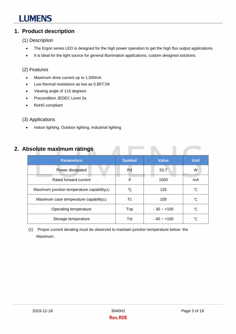
2. Absolute maximum ratings
Parameters Symbol Value Unit
Power dissipated Pd 53.7 W
Rated forward current If 1500 mA
Maximum junction temperature capability(1) Tj 125 ℃
Maximum case temperature capability(1) Tc 105 ℃
Operating temperature Top - 30 ~ +100 ℃
Storage temperature Tst - 40 ~ +100 ℃
(1) Proper current derating must be observed to maintain junction temperature below the
Maximum.
Page 4
2019-12-18 3040H2 Page 4 of 19
Rev.R0E
3. Electro-optical characteristics (Tj=85℃)
Parameters Symbol If(mA) Typ. Unit
Forward voltage Vf 1050 34.2 V
Viewing angle FWHM 2θ1/2 1050 115 degrees
Thermal resistance junction to solder pad Rthj-a
0.85 ℃/W
Lumens maintains a tolerance of 3% on forward voltage measurements.
4. Electro-optical chart (Sorting current, If=1050mA)
Product Description
CRI (Ra)
CCT (K)
If (mA)
Vf(V), typ.
at Tc=65℃
Pd(W), typ
at Tc=65℃
Φv(lm), typ.
at Tc=25℃
lm/W, typ.
at Tc=25℃
Φv(lm), typ.
at Tc=65℃
lm/W, typ.
at Tc=65℃
3040H2-827
80
2700 1050 34.2 35.9 6090 166 5520 154
3040H2-830 3000 1050 34.2 35.9 6430 175 5820 162
3040H2-835 3500 1050 34.2 35.9 6490 177 5880 164
3040H2-840 4000 1050 34.2 35.9 6640 181 6010 167
3040H2-850 5000 1050 34.2 35.9 6770 185 6130 171
3040H2-857 5700 1050 34.2 35.9 6670 182 6040 168
3040H2-927
90
2700 1050 34.2 35.9 5280 144 4780 133
3040H2-930 3000 1050 34.2 35.9 5550 151 5030 140
3040H2-935 3500 1050 34.2 35.9 5620 153 5090 142
3040H2-940 4000 1050 34.2 35.9 5870 160 5320 148
3040H2-950 5000 1050 34.2 35.9 6000 164 5430 151
3040H2-S27
95
2700 1050 34.2 35.9 4590 125 4160 116
3040H2-S30 3000 1050 34.2 35.9 4910 134 4450 124
3040H2-S35 3500 1050 34.2 35.9 4970 136 4500 125
3040H2-S40 4000 1050 34.2 35.9 5290 144 4790 133
Lumens maintains a tolerance of 7% on flux measurements.
Lumens maintains a tolerance of 3% on forward voltage measurements.
Lumens maintains a tolerance of 2 on CRI measurements.
Tc(Case temperature)=65℃ is equal to Tj(Junction temperature)=85℃.
Page 5
2019-12-18 3040H2 Page 5 of 19
Rev.R0E
5. Luminous flux characteristics (Sub current, If=900mA & 1200mA &1500mA)
Product Description
CRI (Ra)
CCT (K)
If (mA)
Vf(V), typ.
at Tc=65℃
Pd(W), typ
at Tc=65℃
Φv(lm), typ.
at Tc=25℃
lm/W, typ.
at Tc=25℃
Φv(lm), typ.
at Tc=65℃
lm/W, typ.
at Tc=65℃
3040H2-827
80
2700 900 33.8 30.4 5300 171 4810 158
3040H2-830 3000 900 33.8 30.4 5600 180 5070 167
3040H2-835 3500 900 33.8 30.4 5650 182 5120 168
3040H2-840 4000 900 33.8 30.4 5780 186 5230 172
3040H2-850 5000 900 33.8 30.4 5900 190 5340 176
3040H2-857 5700 900 33.8 30.4 5810 187 5260 173
3040H2-927
90
2700 900 33.8 30.4 4600 148 4160 137
3040H2-930 3000 900 33.8 30.4 4830 156 4380 144
3040H2-935 3500 900 33.8 30.4 4890 157 4430 146
3040H2-940 4000 900 33.8 30.4 5110 165 4630 152
3040H2-950 5000 900 33.8 30.4 5220 168 4730 155
3040H2-S27
95
2700 900 33.8 30.4 4000 129 3620 119
3040H2-S30 3000 900 33.8 30.4 4270 138 3870 127
3040H2-S35 3500 900 33.8 30.4 4330 139 3920 129
3040H2-S40 4000 900 33.8 30.4 4610 148 4170 137
Product Description
CRI (Ra)
CCT (K)
If (mA)
Vf(V), typ.
at Tc=65℃
Pd(W), typ
at Tc=65℃
Φv(lm), typ.
at Tc=25℃
lm/W, typ.
at Tc=25℃
Φv(lm), typ.
at Tc=65℃
lm/W, typ.
at Tc=65℃
3040H2-827
80
2700 1200 34.8 41.8 6840 161 6200 148
3040H2-830 3000 1200 34.8 41.8 7220 169 6540 157
3040H2-835 3500 1200 34.8 41.8 7290 171 6610 158
3040H2-840 4000 1200 34.8 41.8 7460 175 6750 162
3040H2-850 5000 1200 34.8 41.8 7610 179 6890 165
3040H2-857 5700 1200 34.8 41.8 7490 176 6790 163
3040H2-927
90
2700 1200 34.8 41.8 5930 139 5370 129
3040H2-930 3000 1200 34.8 41.8 6230 146 5650 135
3040H2-935 3500 1200 34.8 41.8 6310 148 5720 137
3040H2-940 4000 1200 34.8 41.8 6590 155 5980 143
3040H2-950 5000 1200 34.8 41.8 6740 158 6100 146
3040H2-S27
95
2700 1200 34.8 41.8 5160 121 4670 112
3040H2-S30 3000 1200 34.8 41.8 5520 130 5000 120
3040H2-S35 3500 1200 34.8 41.8 5580 131 5050 121
3040H2-S40 4000 1200 34.8 41.8 5940 139 5380 129
Lumens maintains a tolerance of 7% on flux measurements.
Lumens maintains a tolerance of 3% on forward voltage measurements.
Lumens maintains a tolerance of 2 on CRI measurements.
Tc(Case temperature)=65℃ is equal to Tj(Junction temperature)=85℃.
Page 6
2019-12-18 3040H2 Page 6 of 19
Rev.R0E
Product Description
CRI (Ra)
CCT (K)
If (mA)
Vf(V), typ.
at Tc=65℃
Pd(W), typ
at Tc=65℃
Φv(lm), typ.
at Tc=25℃
lm/W, typ.
at Tc=25℃
Φv(lm), typ.
at Tc=65℃
lm/W, typ.
at Tc=65℃
3040H2-827
80
2700 1500 35.8 53.7 8220 150 7450 139
3040H2-830 3000 1500 35.8 53.7 8680 159 7860 146
3040H2-835 3500 1500 35.8 53.7 8760 160 7940 148
3040H2-840 4000 1500 35.8 53.7 8970 164 8120 151
3040H2-850 5000 1500 35.8 53.7 9140 167 8280 154
3040H2-857 5700 1500 35.8 53.7 9010 165 8160 152
3040H2-927
90
2700 1500 35.8 53.7 7130 130 6450 120
3040H2-930 3000 1500 35.8 53.7 7490 137 6790 126
3040H2-935 3500 1500 35.8 53.7 7590 139 6870 128
3040H2-940 4000 1500 35.8 53.7 7930 145 7180 134
3040H2-950 5000 1500 35.8 53.7 8100 148 7330 136
3040H2-S27
95
2700 1500 35.8 53.7 6200 113 5620 105
3040H2-S30 3000 1500 35.8 53.7 6630 121 6010 112
3040H2-S35 3500 1500 35.8 53.7 6710 123 6080 113
3040H2-S40 4000 1500 35.8 53.7 7140 130 6470 120
Lumens maintains a tolerance of 7% on flux measurements.
Lumens maintains a tolerance of 3% on forward voltage measurements.
Lumens maintains a tolerance of 2 on CRI measurements.
Tc(Case temperature)=65℃ is equal to Tj(Junction temperature)=85℃.
Page 7
2019-12-18 3040H2 Page 7 of 19
Rev.R0E
6. Chromaticity diagram & coordinates
Lumens maintains a tolerance of 0.005 on chromaticity (CCx, CCy)
CCT(K) x y CCT(K) x y CCT(K) x y
5700K
0.3222 0.3243
4000K
0.3670 0.3578
3000K
0.4147 0.3814
0.3207 0.3462 0.3736 0.3874 0.4299 0.4165
0.3376 0.3616 0.4006 0.4044 0.4562 0.4260
0.3366 0.3369 0.3898 0.3716 0.4373 0.3893
5000K
0.3366 0.3369
3500K
0.3889 0.3690
2700K
0.4373 0.3893
0.3376 0.3616 0.3996 0.4015 0.4562 0.4260
0.3551 0.3760 0.4299 0.4165 0.4813 0.4319
0.3515 0.3487 0.4147 0.3814 0.4593 0.3944
* 3-step MacAdam Ellipse Color Definition
CCT(K) Center Ellipse Parameter
x y Axis a Axis b Angle(°)
5700K 0.3287 0.3417 0.00745 0.00320 59.1
5000K 0.3447 0.3553 0.00822 0.00354 59.6
4000K 0.3818 0.3797 0.00939 0.00402 53.7
3500K 0.4073 0.3917 0.00927 0.00414 54.0
3000K 0.4338 0.4030 0.00834 0.00408 53.2
2700K 0.4578 0.4101 0.00810 0.00420 53.7
0.31
0.33
0.35
0.37
0.39
0.41
0.43
0.45
0.31 0.33 0.35 0.37 0.39 0.41 0.43 0.45 0.47 0.49
CIE
y
CIE x
Black Body Locus
MacAdam 3step
ANSI C78.377A
Page 8
2019-12-18 3040H2 Page 8 of 19
Rev.R0E
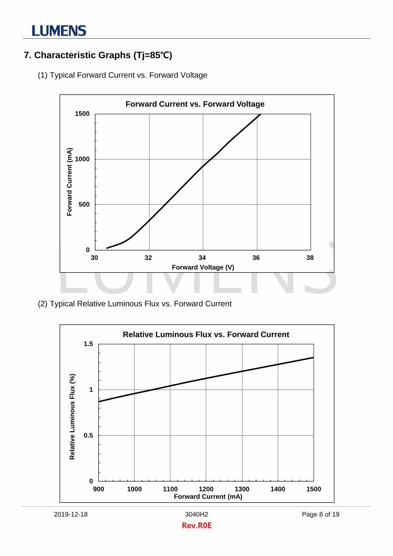
7. Characteristic Graphs (Tj=85℃)
(1) Typical Forward Current vs. Forward Voltage
(2) Typical Relative Luminous Flux vs. Forward Current
0
500
1000
1500
30 32 34 36 38
Fo
rward
Cu
rren
t (m
A)
Forward Voltage (V)
Forward Current vs. Forward Voltage
0
0.5
1
1.5
900 1000 1100 1200 1300 1400 1500
Rela
tiv
e L
um
ino
us F
lux (
%)
Forward Current (mA)
Relative Luminous Flux vs. Forward Current
Page 9
2019-12-18 3040H2 Page 9 of 19
Rev.R0E
(3) Typical Allowable Forward Current with Ambient Temperature
(4) Typical Spatial Radiation Characteristic
0
200
400
600
800
1000
1200
1400
0 25 50 75 100 125
Allo
wab
le F
orw
ard
Cu
rren
t (m
A)
Case Temperature (℃)
Allowable Forward Current vs. Case Temperature
0
0.2
0.4
0.6
0.8
1
-90 -60 -30 0 30 60 90
Rela
tiv
e I
nte
nsit
y (
%)
Angular Displacement (degrees)
Radiation Characteristic
Page 10
2019-12-18 3040H2 Page 10 of 19
Rev.R0E
(5) Spectrum
0
0.2
0.4
0.6
0.8
1
1.2
400 500 600 700 800
Rela
tiv
e I
nte
nsit
y
Wavelength (nm)
Spectral density vs. Wavelength (CRI80)
2700K / 80Ra
3000K / 80Ra
4000K / 80Ra
5700K / 80Ra
0
0.2
0.4
0.6
0.8
1
1.2
400 500 600 700 800
Rela
tiv
e I
nte
nsit
y
Wavelength (nm)
Spectral density vs. Wavelength (CRI90)
3000K / 90Ra
4000K / 90Ra
Page 11
2019-12-18 3040H2 Page 11 of 19
Rev.R0E
0
0.2
0.4
0.6
0.8
1
1.2
400 500 600 700 800
Rela
tiv
e I
nte
nsit
y
Wavelength (nm)
Spectral density vs. Wavelength (CRI95)
3000K / 95Ra
4000K / 95Ra
Page 12
2019-12-18 3040H2 Page 12 of 19
Rev.R0E
8. Outline Dimensions
Package outline (Width x Length x Height) of 28.0 x 28.0 x 1.55mm
Undefined tolerance is ± 0.2 mm
9. Circuit Design
(Unit : mm)
Page 13
2019-12-18 3040H2 Page 13 of 19
Rev.R0E
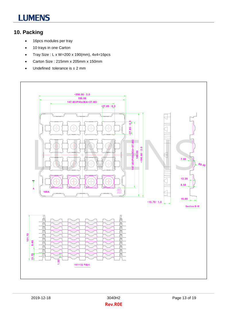
10. Packing
16pcs modules per tray
10 trays in one Carton
Tray Size : L x W=200 x 190(mm), 4x4=16pcs
Carton Size : 215mm x 205mm x 150mm
Undefined tolerance is ± 2 mm
10(11)단 적층시
15.7
08.6
0101.7
0
1.5
0
16EA
A
Section B-B'
10(11)단 적층시
+
-ERC 3070
+
-ERC 3070
+
-ERC 3070
+
-ERC 3070
*27.85±0.3
*27.8
5±
0.3
147.85(P40x3EA+27.85)
196.00
*200.00±2.0
147.8
5(P
40x3E
A+27.8
5)
186.0
0
*190.0
0±
2.0
*15.70±1.0
15.00
8.50
12.20
7.90
R9.45
15.7
08.6
0101.7
0
1.5
0
Page 14
2019-12-18 3040H2 Page 14 of 19
Rev.R0E
1Tray unit = 16pcs (4x4 Array) 1Set = 11Tray (10Tray+1Cover)
Tray Size = 200mm(L) * 190mm(W) Total size = 200mm(L)*190mm(W)*103mm(H)
Quantity = 16*10=160pcs
Box size = 215mm(L)*205mm(W)*150mm(H) Poly-bag size = 275*435*160mm
Attached label : Production Info. 1Set + Dry-Pack + Humidity Indicator
Quantity = 160pcs Quantity = 160pcs
+
-ERC 3070
+
-ERC 3070
+
-ERC 3070
+
-ERC 3070
16EA
*200.00±2.0
*190.0
0±
2.0
10(11)단 적층시
15.7
08.6
0101.7
0
1.5
0
16EA
A
Section B-B'
10(11)단 적층시
+
-ERC 3070
+
-ERC 3070
+
-ERC 3070
+
-ERC 3070
*27.85±0.3
*27.8
5±
0.3
147.85(P40x3EA+27.85)
196.00
*200.00±2.0
147.8
5(P
40x3E
A+27.8
5)
186.0
0
*190.0
0±
2.0
*15.70±1.0
15.00
8.50
12.20
7.90
R9.45
15.7
08.6
0101.7
0
1.5
0
Page 15
2019-12-18 3040H2 Page 15 of 19
Rev.R0E
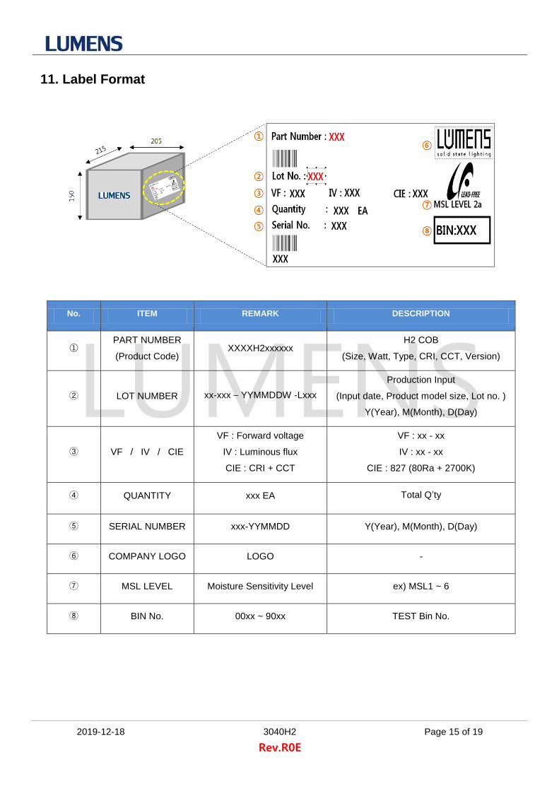
11. Label Format
No. ITEM REMARK DESCRIPTION
① PART NUMBER
(Product Code) XXXXH2xxxxxx
H2 COB
(Size, Watt, Type, CRI, CCT, Version)
② LOT NUMBER xx-xxx – YYMMDDW -Lxxx
Production Input
(Input date, Product model size, Lot no. )
Y(Year), M(Month), D(Day)
③ VF / IV / CIE
VF : Forward voltage
IV : Luminous flux
CIE : CRI + CCT
VF : xx - xx
IV : xx - xx
CIE : 827 (80Ra + 2700K)
④ QUANTITY xxx EA Total Q’ty
⑤ SERIAL NUMBER xxx-YYMMDD Y(Year), M(Month), D(Day)
⑥ COMPANY LOGO LOGO -
⑦ MSL LEVEL Moisture Sensitivity Level ex) MSL1 ~ 6
⑧ BIN No. 00xx ~ 90xx TEST Bin No.
Page 16
2019-12-18 3040H2 Page 16 of 19
Rev.R0E
12. Product Code
Color Code Product Code Remark
827 1309H2827xxx 1318H2827xxx 2025H2827xxx 2032H2827xxx 3040H2827xxx
CRI80
830 1309H2830xxx 1318H2830xxx 2025H2830xxx 2032H2830xxx 3040H2830xxx
835 1309H2835xxx 1318H2835xxx 2025H2835xxx 2032H2835xxx 3040H2835xxx
840 1309H2840xxx 1318H2840xxx 2025H2840xxx 2032H2840xxx 3040H2840xxx
850 1309H2850xxx 1318H2850xxx 2025H2850xxx 2032H2850xxx 3040H2850xxx
857 1309H2857xxx 1318H2857xxx 2025H2857xxx 2032H2857xxx 3040H2857xxx
927 1309H2927xxx 1318H2927xxx 2025H2927xxx 2032H2927xxx 3040H2927xxx
CRI90 930 1309H2930xxx 1318H2930xxx 2025H2930xxx 2032H2930xxx 3040H2930xxx
935 1309H2935xxx 1318H2935xxx 2025H2935xxx 2032H2935xxx 3040H2935xxx
940 1309H2940xxx 1318H2940xxx 2025H2940xxx 2032H2940xxx 3040H2940xxx
S27 1309H2S27xxx 1318H2S27xxx 2025H2S27xxx 2032H2S27xxx 3040H2S27xxx
CRI95 S30 1309H2S30xxx 1318H2S30xxx 2025H2S30xxx 2032H2S30xxx 3040H2S30xxx
S35 1309H2S35xxx 1318H2S35xxx 2025H2S35xxx 2032H2S35xxx 3040H2S35xxx
S40 1309H2S40xxx 1318H2S40xxx 2025H2S40xxx 2032H2S40xxx 3040H2S40xxx
Product Code Nomenclature detail
Size + Watt
(2) (2)
Type CRI CCT Version
(2) (1) (2) (3)
XXXX H2 8 : 80Ra 27 : 2700K xxx
9 : 90Ra 30 : 3000K
S : 95Ra 35 : 3500K
40 : 4000K
50 : 5000K
57 : 5700K
Serial number Nomenclature detail
Item
(1)
Product
(1)
Type Date (YYMM) Input # Machine Lot number
(1) (4) (2) (1) (3)
C : COB A A 1910 AX : A1~A9 A 001
B B BX : B1~B9 B 002
C C CX : C1~C9 C 003
D D
DX : D1~D9 D 004
•
•
•
•
•
•
•
•
•
•
•
•
•
•
•
Z Z
ZX : Z1~Z9 Z 999
Page 17
2019-12-18 3040H2 Page 17 of 19
Rev.R0E
Marking
13. Reliability test items and conditions
Item Reference Test Conditions Duration Cycle
Thermal Shock EIAJ
ED-4701 Ta = - 40℃ (30min) ~ 100℃ (30min) 100 Cycle
Room temperature Operating Life Test
Internal Reference
Ta = 25℃, If = Maximum current 1,000 Hours
High Temperature Operating Life Test
Internal Reference
Ta = 85℃, If = Sorting current 1,000 Hours
High Temperature High Humidity Life Test
Internal Reference
Ta = 85℃, 85% RH 1,000 Hours
Low Temperature Storage Test Internal
Reference Ta = -40℃ 1,000 Hours
High Temperature Storage Test Internal
Reference Ta = 100℃ 1,000 Hours
(1) Criteria for judging the damage
Item Symbol Condition
Criteria for Judgment
MIN MAX
Forward Voltage Vf If = 1050mA - USL (1) × 1.1
Luminous Intensity Φv If = 1050mA LSL (2) × 0.7 -
USL : Upper Standard Level
LSL : Lower Standard Level
3040H2830xxx
CSE-19xxJ2-A001
1309H2830xxx
CSE-19xxJ2-A001
1318H2830xxx
CSE-19xxJ2-A001
2025H2830xxx
CSE-19xxJ2-A001
2032H2830xxx
CSE-19xxJ2-A001
Product code
Serial number
Product code
Serial number
Product code
Serial number
Product code
Serial number
Product code
Serial number
Page 18
2019-12-18 3040H2 Page 18 of 19
Rev.R0E
14. Cautions
(1) Moisture-Proof Package
1.1 When moisture is absorbed into the LED package it may vaporize and expand products during soldering.
There is a possibility that this may cause exfoliation of the contacts and damage to the optical
characteristics of the LEDs. For this reason, the moisture-proof package is used to keep moisture to a
minimum in the package.
1.2 A package of a moisture-absorbent material (silica gel) is inserted into the shielding bag. The silica gel
changes its color from blue to pink as it absorbs moisture.
(2) Current limiting
A resistor should be used to limit current spikes that can be caused by voltage fluctuations.
Otherwise damage could occur.
(3) Storage Conditions
3.1 Before opening the package: The LEDs should be kept at 30℃ or less and 90%RH or less. The LEDs
should be used within a year. When storing the LEDs, moisture-proof packaging with moisture-absorbent
material (silica gel) is recommended.
3.2 After opening the package: The LEDs should be kept at 30℃ or less and 70%RH or less. The LEDs
should be soldered within 168 hours (7 days) after opening the package. If unused LEDs remain, they
should be stored in moisture-proof packages, such as sealed containers with packages of moisture-
absorbent material (silica gel). It is also recommended to return the LEDs to the original moisture-proof
bag and to reseal the moisture-proof bag again.
3.3 If the moisture-absorbent material (silica gel) has faded away or the LEDs have exceeded the
recommended storage time, baking treatment should be performed using the following conditions.
Baking treatment: more than 24 hours at 65±5℃
3.4 Lumens LED electrode sections are comprised of a silver-plated copper alloy. The silver surface may be
affected by environments which contain corrosive gases and so on. Please avoid condition which may
cause difficulty environments during soldering operations. It is recommended that the user uses the
LEDs as soon as possible.
3.5 Please avoid rapid transitions in ambient temperature, especially in high humidity environments where
condensation can occur.
Page 19
2019-12-18 3040H2 Page 19 of 19
Rev.R0E
(4) Handling of Silicone (Lens) LEDs
4.1 Avoid silicone resin parts especially with sharp tools such as tweezers.
4.2 Avoid leaving fingerprints on silicone lens part.
(5) Usage
5.1 Do not exceed the values given in this specification.
NOTE :
All the information published is considered to be reliable. However, Lumens does not assume any liability
arising out of the application or use of any product described herein.
Lumens reserves the right to make changes at any time without notice to any products in order to improve
reliability, function or design.
Lumens products are not authorized for use as critical components in life support devices or systems without
the express written approval from the managing director of Lumens.