13
www.data-modul.de DATA MODUL AG Landsberger Str. 322 80687 München Tel.: 089/ 56017-0 Fax 089/ 56017-119 BATRON 0 Specification for Version July 2003 BTHQ 42008VSS-SMN-LEDwhite

www.data-modul.deDATA MODUL AG Landsberger Str. 322 80687 München Tel.: 089/ 56017-0 Fax 089/ 56017-119
BATRON
0
Specification for
Version July 2003
BTHQ 42008VSS-SMN-LEDwhite

VL-FS-BTHQ 42008VSS-08 REV. A (BTHQ 42008VSS-SMN-LEDwhite)
JULY/2003
PAGE 2 OF 13
DOCUMENT REVISION HISTORY 1:
DOCUMENTREVISION
FROM TO
DATE DESCRIPTION CHANGEDBY
CHECKED
BY A 2003.07.15 First Release. HELEN HE LU MIN
YUAN
www.data-modul.deDATA MODUL AG Landsberger Str. 322 80687 München Tel.: 089/ 56017-0 Fax 089/ 56017-119

VL-FS-BTHQ 42008VSS-08 REV. A(BTHQ 42008VSS-SMN-LEDwhite)
JULY/2003
PAGE 3 OF 13
CONTENTS
Page No.
1. GENERAL DESCRIPTION 4
2. MECHANICAL SPECIFICATIONS 4
3. BACKLIGHT SPECIFICATION 6
4. INTERFACE SIGNALS 7
5. ABSOLUTE MAXIMUM RATINGS 85.1 ELECTRICAL MAXIMUM RATINGS (Ta=25 C) 85.2 ENVIRONMENTAL CONDITION 8
6. ELECTRICAL SPECIFICATIONS 96.1 TYPICAL ELECTRICAL CHARACTERISTICS 96.2 TIMING SPECIFICATIONS 106.3 TIMING DIAGRAM OF VDD AGAINST V0 126.4 CHARACTER GENERATOR ROM (KS0066U-10B) 13
www.data-modul.deDATA MODUL AG Landsberger Str. 322 80687 München Tel.: 089/ 56017-0 Fax 089/ 56017-119

VL-FS-BTHQ 42008VSS-08 REV. A(BTHQ 42008VSS-SMN-LEDwhite)
JULY/2003
PAGE 4 OF 13
Specificationof
LCD Module Type Model No.: BTHQ 42008VSS-08
1. General Description
20 characters (5 x 8 dots) x 4 line STN Negative Blue Transmissive LCD Character Module.
Viewing Angle: 6 O’clock direction.
Driving duty: 1/16 Duty, 1/5 bias.
‘SAMSUNG’ KS0066UP-10BCC (Die) LCD Controller & Driver or equivalent.
‘SAMSUNG’ KS0065B-PCC (Die) LCD Segment Drivers or equivalent.
White LED01 backlight.
2. Mechanical Specifications
The mechanical detail is shown in Fig. 1 and summarized in Table 1 below.
Table 1
Parameter Specifications UnitOutline dimensions 146.0(W) x 62.5(H) x 13.0 MAX.(D) mm Viewing area 123.0(W) x 42.5(H) mm Active area 118.84(W) x 38.47(H) mm Display format 20 characters x 4 lines -Character size 4.84(W) x 9.22(H) (5 x 8 dots) mm Character spacing 1.16(W) x 0.53(H) mm Character pitch 6.00(W) x 9.75(H) mm Dot size 0.956(W) x 1.139(H) mm Dot spacing 0.015(W) x 0.015(H) mm Dot pitch 0.971(W) x 1.154(H) mm Weight: Approx. 131.0 grams
www.data-modul.deDATA MODUL AG Landsberger Str. 322 80687 München Tel.: 089/ 56017-0 Fax 089/ 56017-119

VL-FS-BTHQ 42008VSS-08 REV. A(BTHQ 42008VSS-SMN-LEDwhite)
JULY/2003
PAGE 5 OF 13
Figure 1: Module Specification
www.data-modul.deDATA MODUL AG Landsberger Str. 322 80687 München Tel.: 089/ 56017-0 Fax 089/ 56017-119

VL-FS-BTHQ 42008VSS-08 REV. A(BTHQ 42008VSS-SMN-LEDwhite)
JULY/2003
PAGE 6 OF 13
3. Backlight Specification
Figure 2: Backlight Specification
www.data-modul.deDATA MODUL AG Landsberger Str. 322 80687 München Tel.: 089/ 56017-0 Fax 089/ 56017-119

VL-FS-BTHQ 42008VSS-08 REV. A(BTHQ 42008VSS-SMN-LEDwhite)
JULY/2003
PAGE 7 OF 13
4. Interface signals
Table 2: Pin assignment
Pin No. Symbol Description1 VSS Ground (0V) 2 VDD Power supply for logic (+5V) 3 V0 Power supply for LCD driver 4 RS Register Select Input:
“High” for Data register (for read and write), “Low” for Instruction register (for write),
Busy flag, address counter (for read). 5 R/W Read/Write signal:
“High” for Read mode. “Low” for Write mode.
6 E Enable. Start signal for data read /write. 7 DB0 Data input/output (LSB) 8 DB1 Data input/output 9 DB2 Data input/output 10 DB3 Data input/output 11 DB4 Data input/output 12 DB5 Data input/output 13 DB6 Data input/output 14 DB7 Data input/output (MSB) A LED(+) Anode of LED Backlight K LED(-) Cathode of LED Backlight
www.data-modul.deDATA MODUL AG Landsberger Str. 322 80687 München Tel.: 089/ 56017-0 Fax 089/ 56017-119

VL-FS-BTHQ 42008VSS-08 REV. A(BTHQ 42008VSS-SMN-LEDwhite)
JULY/2003
PAGE 8 OF 13
5. Absolute Maximum Ratings
5.1 Electrical Maximum Ratings (Ta = 25 ºC)
Table 3
Parameter Symbol Min. Max. UnitPower Supply voltage (Logic) VDD - VSS -0.3 +7.0 VPower Supply voltage (LCD drive)
VLCD=VDD- V0
-0.3 +15.0 V
Input voltage Vin -0.3 VDD+0.3 V
Note:
The modules may be destroyed if they are used beyond the absolute maximum ratings.
All voltage values are referenced to VSS = 0V.
5.2 Environmental Condition
Table 4
OperatingTemperature
(Topr)
StorageTemperature
(Tstg) Item
Min. Max. Min. Max.
Remark
Ambient Temperature 0 C +50 C -10 C +60 C DryHumidity 95% max. RH for Ta 40 C
< 95% RH for Ta > 40 Cno condensation
Vibration (IEC 68-2-6) cells must be mounted on a suitable connector
Frequency: 10 55 Hz Amplitude: 0.75 mm Duration: 20 cycles in each direction.
3 directions
Shock (IEC 68-2-27) Half-sine pulse shape
Pulse duration : 11 ms Peak acceleration: 981 m/s2 = 100g Number of shocks : 3 shocks in 3 mutually perpendicular axes.
3 directions
www.data-modul.deDATA MODUL AG Landsberger Str. 322 80687 München Tel.: 089/ 56017-0 Fax 089/ 56017-119

VL-FS-BTHQ 42008VSS-08 REV. A(BTHQ 42008VSS-SMN-LEDwhite)
JULY/2003
PAGE 9 OF 13
6. Electrical Specifications
6.1 Typical Electrical Characteristics
At Ta = 25 C, VDD = 5V 5%, VSS=0V.
Table 5
Parameter Symbol Conditions Min. Typ. Max. Unit
Supply voltage (Logic) VDD-VSS 4.75 5.0 5.25 VVDD =5.0V, Ta=0 C,Note1.
- 5.1 - V
VDD =5.0V, Ta=25 C,Note1.
4.5 4.7 4.9 V
Supply voltage (LCD) VLCD=VDD-V0
VDD =5.0V, Ta=50 C,Note1.
- 4.6 - V
VIH “H” level 2.2 - VDD VInput signal voltage for E,DB0-DB7,R/W,RS. VIL “L” level -0.3 - 0.6 VSupply Current (Logic & LCD)
IDD VDD = 5V, Character mode
- 2.0 3.0 mA
Supply Current (LCD) I0 VDD = 5V, Character mode, Note (1).
- 1.0 1.5 mA
Supply voltage of white LED01 backlight
VLED01 Forward current =80mA
Number of LED dies =1x4=4
3.9 4.0 4.1 V
Note (1) : There is tolerance in optimum LCD driving voltage during production and it will be within
the specified range.
www.data-modul.deDATA MODUL AG Landsberger Str. 322 80687 München Tel.: 089/ 56017-0 Fax 089/ 56017-119

VL-FS-BTHQ 42008VSS-08 REV. A(BTHQ 42008VSS-SMN-LEDwhite)
JULY/2003
PAGE 10 OF 13
6.2 Timing Specifications
At Ta =0 C to +50 C , VDD = +5V 5% ,VSS = 0V.
Refer to Fig. 3, the write mode timing diagram.
Table 6
Parameter Symbol Min. Max. UnitE Cycle Time tc 500 - nsE Rise/Fall Time tR,tF - 20 nsE Pulse Width(high, low) tW 230 - nsR/W and RS Setup Time tSU1 40 - nsR/W and RS Hold Time tH1 10 - nsData Set-up Time tSU2 80 - nsData Hold Time tH2 10 - ns
Refer to Fig. 4, the bus timing diagram for read mode.
Table 7
Parameter Symbol Min. Max. UnitE Cycle Time tc 500 - nsE Rise/Fall Time tR,tF - 20 nsE Pulse Width(high, low) tW 230 - nsR/W and RS Setup Time tSU 40 - nsR/W and RS Hold Time tH 10 - nsData Output Delay Time tD - 120 nsData Hold Time tDH 5 - ns
www.data-modul.deDATA MODUL AG Landsberger Str. 322 80687 München Tel.: 089/ 56017-0 Fax 089/ 56017-119

VL-FS-BTHQ 42008VSS-08 REV. A(BTHQ 42008VSS-SMN-LEDwhite)
JULY/2003
PAGE 11 OF 13
Figure 3: Write Mode Timing Diagram
Figure 4: Read Mode Timing Diagram
www.data-modul.deDATA MODUL AG Landsberger Str. 322 80687 München Tel.: 089/ 56017-0 Fax 089/ 56017-119
VL-FS-BTHQ 42008VSS-08 REV. A(BTHQ 42008VSS-SMN-LEDwhite)
JULY/2003
PAGE 12 OF 13
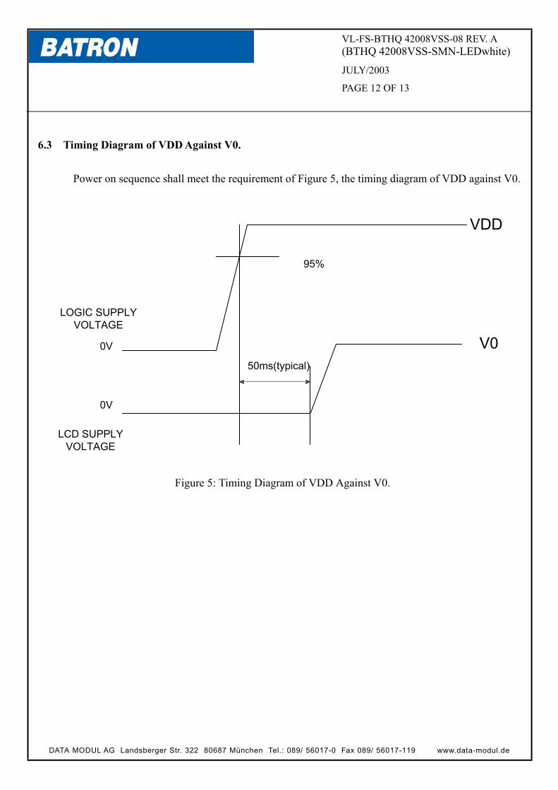
6.3 Timing Diagram of VDD Against V0.
Power on sequence shall meet the requirement of Figure 5, the timing diagram of VDD against V0.
VDD
0V
0V
V0
95%
50ms(typical)
LOGIC SUPPLYVOLTAGE
LCD SUPPLYVOLTAGE
Figure 5: Timing Diagram of VDD Against V0.
www.data-modul.deDATA MODUL AG Landsberger Str. 322 80687 München Tel.: 089/ 56017-0 Fax 089/ 56017-119
VL-FS-BTHQ 42008VSS-08 REV. A(BTHQ 42008VSS-SMN-LEDwhite)
JULY/2003
PAGE 13 OF 13
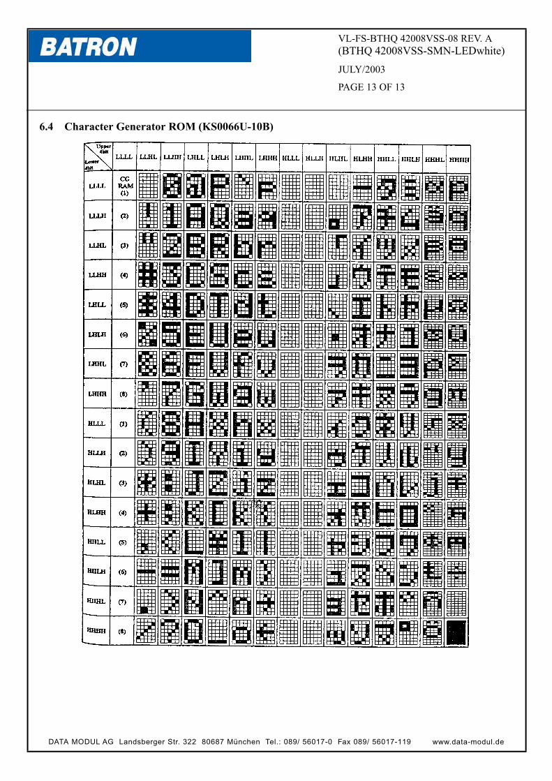
6.4 Character Generator ROM (KS0066U-10B)
www.data-modul.deDATA MODUL AG Landsberger Str. 322 80687 München Tel.: 089/ 56017-0 Fax 089/ 56017-119


