Efficiency Engineering Inc. Jan-11 Preface Page 1 of 67 Specification for Evaporative Condenser Retrofit at Exhibition Arena 70 Division Street Guelph, ON www.guelph.ca Prepared by: Cambridge, Ontario 519-624-9965 www.ee-solutions.com EEI Project: 0931 January 2011
Transcript
Efficiency Engineering Inc. Jan-11 Preface Page 1 of 67
Specification for Evaporative Condenser Retrofit at
Efficiency Engineering Inc. Jan-11 Preface Page 2 of 67
Table of Contents 00015 – List of Drawings, Master Drawings .................................................................................... 3 00030 – Project Management and Quality Control .......................................................................... 4 01000 – General Conditions ............................................................................................................ 5 02050 – Demolition ........................................................................................................................ 10 13175 – Ice Rink Systems, General Requirements ....................................................................... 12 15010 – Mechanical General Requirements.................................................................................. 15 15030 – Record Drawings.............................................................................................................. 19 15031 – Shop Drawings ................................................................................................................. 20 15047 – Identification ..................................................................................................................... 21 15056 – Nameplates ...................................................................................................................... 23 15057 – Valve Tags and Charts .................................................................................................... 24 15059 – Cleaning and Protection ................................................................................................... 25 15080 – Cutting and Patching ........................................................................................................ 26 15094 – Hangers and Supports ..................................................................................................... 27 15169 – Indicating Instruments ...................................................................................................... 30 15780 – Variable Frequency Drives for Fans and Pumps ............................................................. 32 16010 – Electrical General Requirements ..................................................................................... 36 16060 – Electrical Demolition ........................................................................................................ 41 16111 – Conduit ............................................................................................................................. 43 16120 – Wire and Cable ................................................................................................................ 45 16130 – Boxes ............................................................................................................................... 50 16141 – Wiring Devices ................................................................................................................. 53 16160 – Control Panel ................................................................................................................... 56 16190 – Electrical Identification ..................................................................................................... 59 16440 – Disconnect Switches ........................................................................................................ 61 16500 – Facility Start-Up and Commissioning ............................................................................... 62
Efficiency Engineering Inc. Jan-11 Section 00015 Page 3 of 67
00015 – List of Drawings, Master Drawings
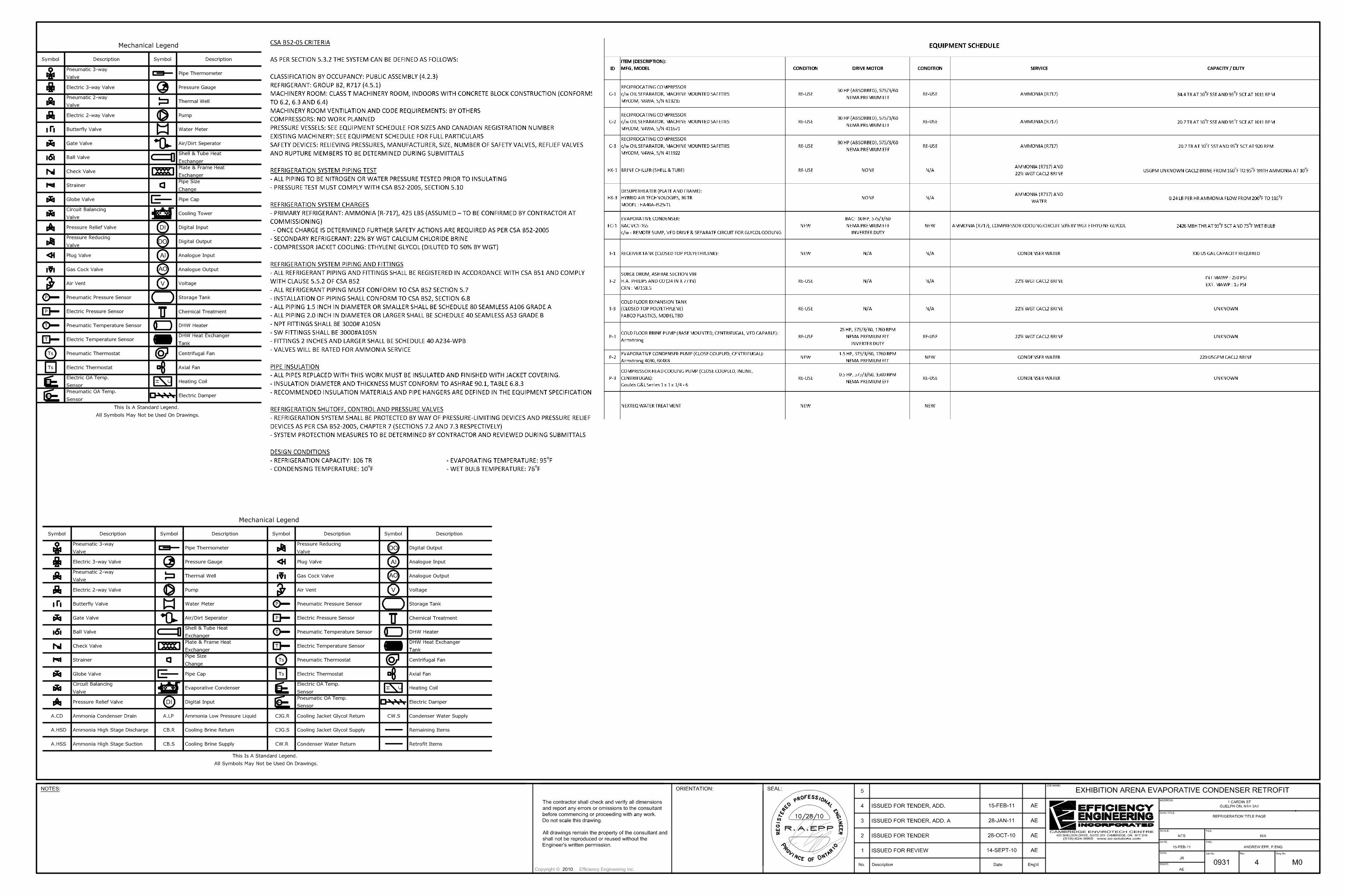
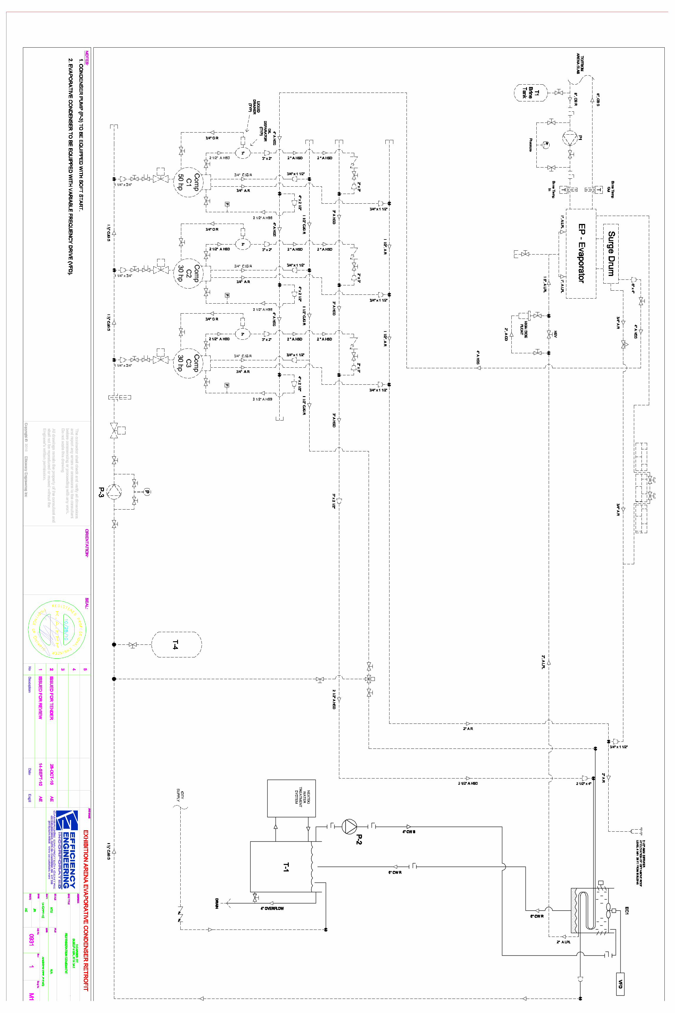
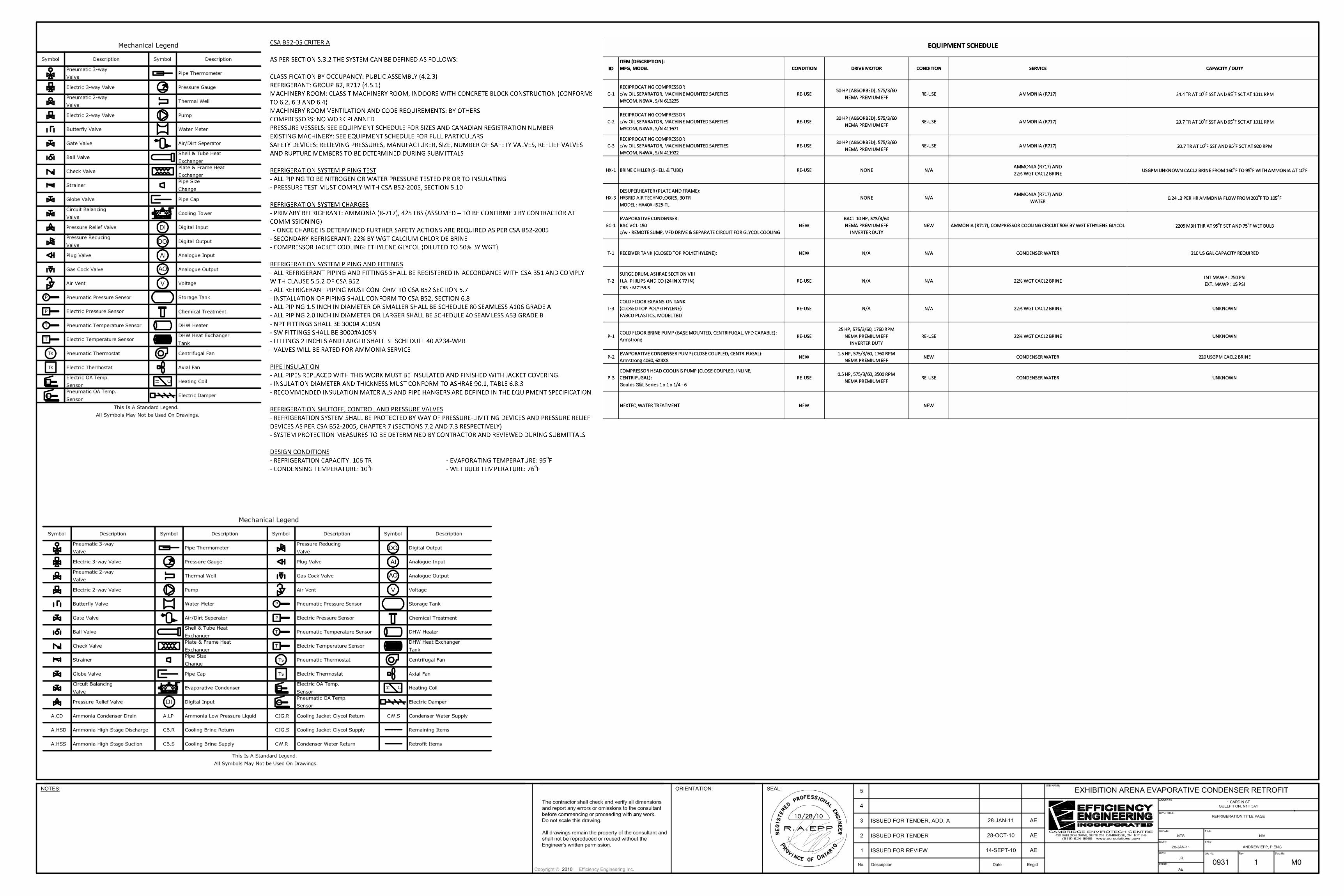
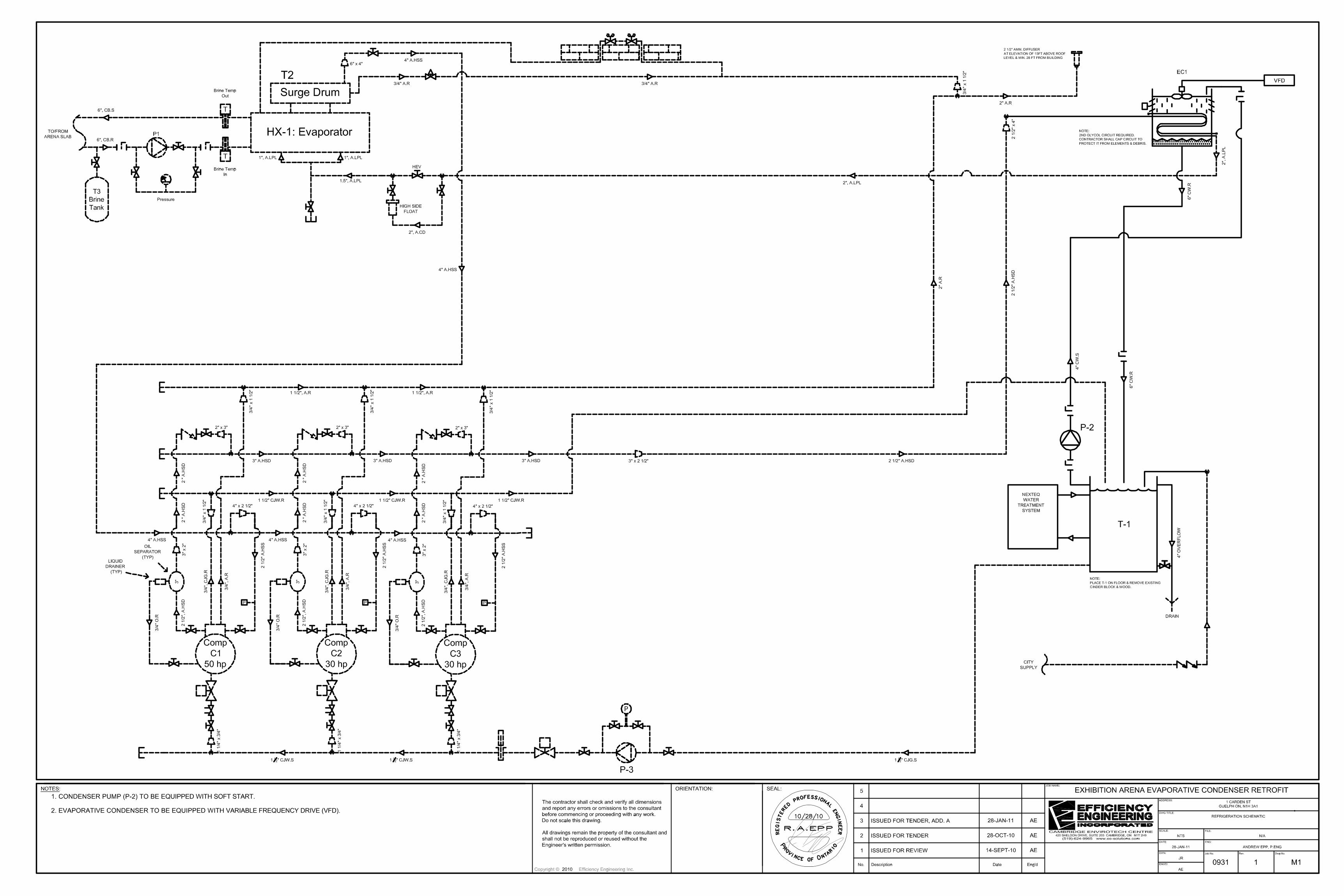
MASTER DRAWINGS (NOT INCLUDED WITH THIS DOCUMENT) M0 Refrigeration Title Page and Notes M1 Refrigeration Schematic S1 Key Plan and General Notes S2 Roof Framing Plan S3 Section & Steel Notes S4 Section & Steel Notes S5 Section & Steel Notes
Drawings which accompany these Specifications are diagrammatic and indicate general arrangement of the systems and work included in the contract. Misinterpretation of any requirements of either the drawings or specifications will not relieve the Contractor of responsibility to complete the work. END OF 00015
Efficiency Engineering Inc. Jan-11 Section 00030 Page 4 of 67
00030 – Project Management and Quality Control
1.0 GENERAL .1 Efficiency Engineering Inc. is acting as the Owner’s representative for the Work, to ensure timely
progress, completeness, and specified quality.
2.0 SITE REVIEWS .1 The Engineer shall conduct site reviews throughout construction and will be checking for the items
listed herein. .2 The Work will not be considered substantially complete until all items herein are found by the Engineer
to be Acceptable.
3.0 SUBMITTALS AND NOTIFICATIONS .1 All submittals and notifications indicated in this specification will be required by the Engineer in a
timely fashion. Equipment and materials submittals shall be provided prior to construction. Performance submittals shall be provided as soon as possible after equipment has been placed into service. Closeout submittals shall be provided upon substantial completion of the Work.
.2 The Engineer will provide a condensed list of submittal and notification requirements to the Contractor shortly after award of Contract.
.3 All equipment and materials submittals shall be provided before the Pre-Construction meeting is scheduled.
.4 The Engineer will make all reasonable efforts to review and return submittals quickly, with a standard of 10 working days from delivery to the Engineer’s office.
4.0 PRE-CONSTRUCTION (KICKOFF) MEETING .1 The Owner will convene a project Pre-Construction meeting with the Engineer and Contractor shortly
after Contract award. .2 The Contractor shall be represented by the assigned project manager at a minimum. .3 No construction or demolition may proceed prior to this meeting. .4 The intent of the kickoff meeting will be to finalize the construction schedule, to agree on quality
standards, to review and acknowledge required submittals and notifications, and to agree on business procedures.
.5 The Engineer will provide minutes of the kickoff meeting. .1 The Contractor will have five working days to respond to the minutes of the meeting, if any
amendment or clarification is sought. Failure to seek changes to the minutes will signify agreement to all of the items documented in the minutes.
END OF 00030
Efficiency Engineering Inc. Jan-11 Section 01000 Page 5 of 67
01000 – General Conditions
1.0. GENERAL
1.1. FACILITY LOCATION .1 This project shall be undertaken at Exhibition Arena, 70 Division Street, Guelph ON, N1H 1R5
1.2 TERMINOLOGY .1 For the purposes of this tender, the following terminology shall be used:
.1 Contractor - the Successful Bidder
.2 Owner (Site Contact and Construction Issues) City of Guelph Facilities department represented by Samantha Jansen, (519) 822-1260, ext 2759, email:
.4 Engineer - Efficiency Engineering Inc., represented by Andrew Epp, P.Eng, PMP, [email protected]
(519) 624-9965, email: [email protected] .5 The Work - This project in its entirety, as specified herein and on accompanying drawing and
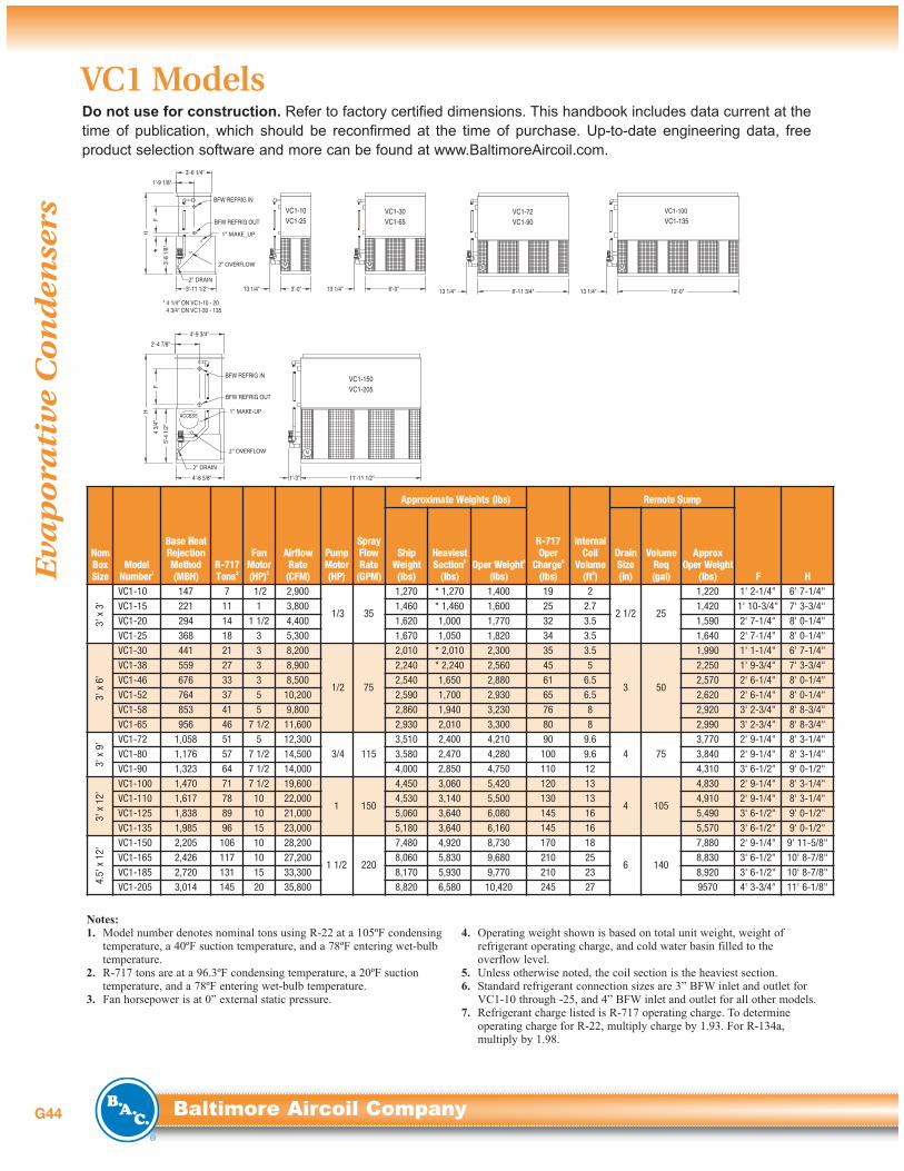
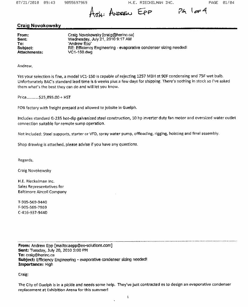
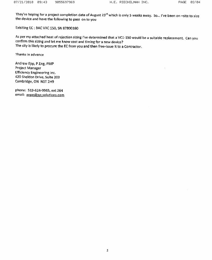
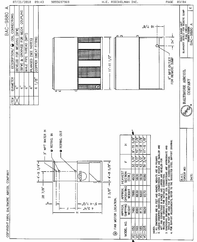
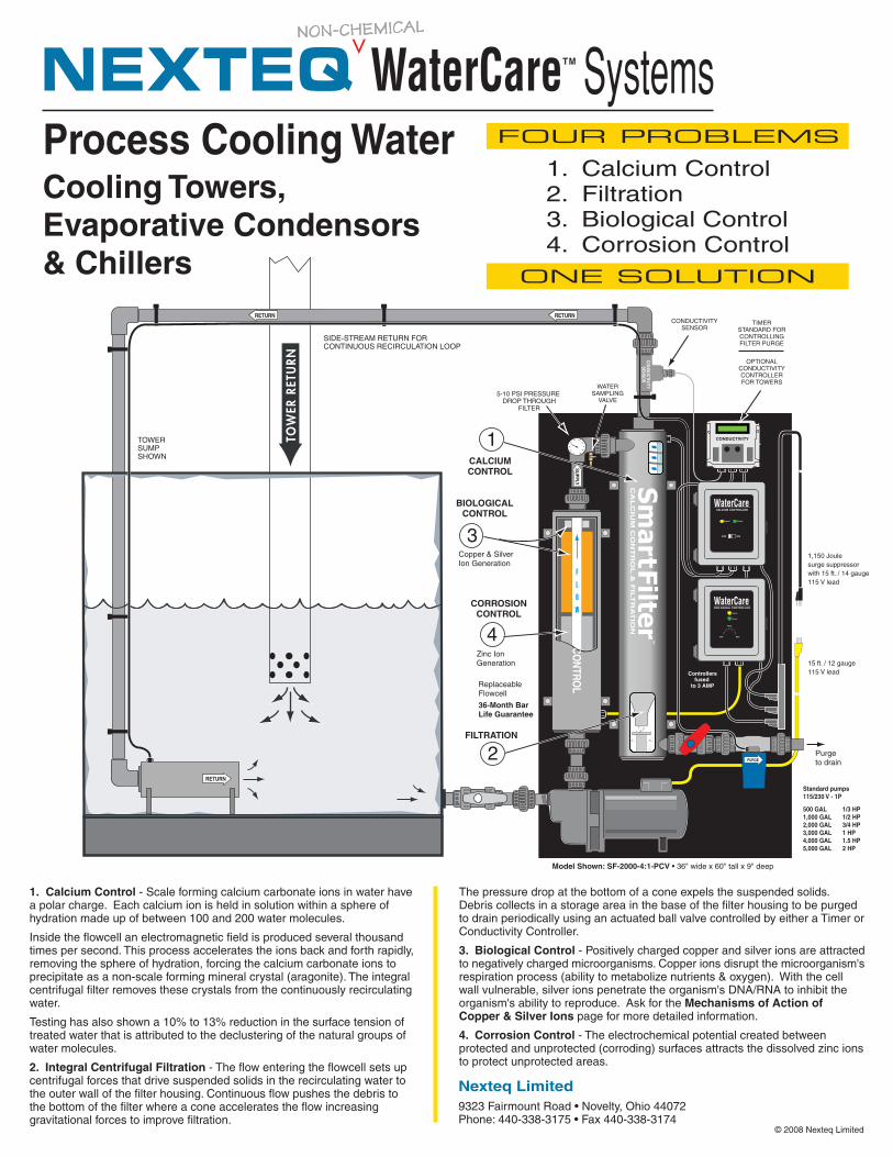
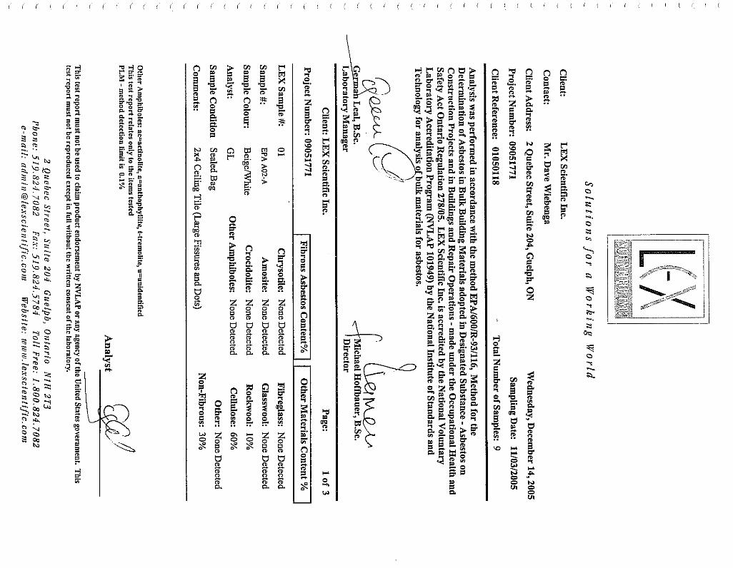
summarized as follows: .1 Replace existing evaporative condenser and associated components .1 Replace existing device with one (1) BAC VC1-150 evaporative condenser .2 See Appendix A for BAC Product Specifications .3 Replace receiver tank with 210 usgal capacity closed top polyethylene unit; .4 Replace existing evaporative condenser pump with new device (suggested
Armstrong 4030, 1.5 hp, 220 usgpm); .5 Install Nexteq Water treatment system (see Appendix C for Product Specification) .6 Replace all process piping required.
.2 Perform required structural re-enforcements to roof to accommodate new evaporative condenser (see Appendix B).
.1 Corroded joist to be reinforced with 7/8” diameter continuous steel bar (top and bottom chord);
.2 Corroded areas are to be cleaned and treated with zinc rich coating;
1.3 INSPECTION OF WORK .1 The Owner or Engineer shall be entitled to inspect the work at any time. Prior to completion of the
work, the Contractor shall request that the Engineer inspect the work. The Engineer shall be the judge of whether the work is adequate, complete, and performed in accordance with the Contract. Any deficiencies in the work shall be corrected by the Contractor at his expense prior to final payment.
1.4 WASTE MANAGEMENT PRACTICES .1 The Contractor shall reduce, reuse, and/or recycle waste in undertaking work under this Contract,
where applicable. The Contractor shall comply with the Environmental Protection Act.
1.5 REGULATORY REQUIREMENTS .1 Materials and workmanship shall be in accordance with requirements and recommendations of
applicable rules, regulations, standards and codes as specified hereunder. All products shall bear a certification label of CSA, CGA, TSSA, ULC, or ESA, as applicable. .1 ESA Electrical Safety Code (Canadian Electrical Code and Electrical Safety Authority
Supplements); .2 Canadian Standards Association (CSA); .3 Underwriter's Laboratories of Canada (ULC); .4 Ministry of Health (MOH); .5 Ontario Building Code (OBC); .6 Ontario Fire Code (OFC); .7 Boards, Services, Companies or other Authorities having jurisdiction; .8 Technical Standards and Safety Authority (TSSA);
Efficiency Engineering Inc. Jan-11 Section 01000 Page 6 of 67
.2 PERMITS, FEES, AND CERTIFICATES – The Contractor shall give notices, obtain permits, and pay all fees required for work under the Contract. Before the Owner issues final certification of payment, these certificates shall be furnished as evidence that work installed conforms to laws and regulations of all governing authorities. The Contractor is expected to determine the requirements of local authorities having jurisdiction and conform to those requirements.
1.6 LABOUR .1 The work shall be performed by persons experienced and skilled in the work. The Contractor shall
provide effective supervision of the work, and shall employ local labour where practicable. The hours of work, wages paid, terms of employment, and working conditions shall conform to labour agreements and all applicable legislation and guidelines issued from time to time by the Ontario Ministry of Labour and governing authorities.
1.7 SUB-CONTRACTS .1 The Contractor may assign or subcontract any part of the Contract. However, all subcontractors and
their contribution shall be clearly identified as part of the bid submission. After award of the Contract, the Contractor shall neither assign nor sub-contract any part of the Contract without the prior written consent of the Engineer. Every subcontract entered into by the Contractor shall adopt all of the terms and conditions of the Contract.
.2 The Contractor shall be responsible to the Owner for the acts and omissions of its subcontractors and suppliers, and of persons directly or indirectly employed by them. Nothing contained in the Contract shall create any contractual relationship between any sub-contractor or supplier and the Owner.
1.8 MATERIALS SUPPLIED .1 The Contractor shall supply only new materials and components for the Work. Used, re-
manufactured, or rebuilt components shall not be used except as expressly permitted herein. .2 Products shall be provided with complete documentation. Undocumented products must be tagged
and accepted by the Engineer prior to installation. Do not install undocumented products without such acceptance.
.3 All products and materials shall be new, clean, and free of defects, damage and corrosion.
.4 The Contractor shall ship and store products and materials in a manner that will protect them from damage, weather, and entry of debris. Damaged products or materials cannot be installed and the Contractor is obliged to take immediate steps to obtain replacements or implement repairs.
1.9 CHANGES IN THE WORK .1 Change orders shall be issued and fees adjusted only where the Owner makes a significant change in
the project scope as outlined herein. Extras shall not be granted due to the Contractor's unfamiliarity with the site, or due to the Contractor's lack of thorough investigation prior to bid submission. Any additions to the Work under this contract shall conform to all construction standards and conditions laid out herein, whether or not such conditions are expressly stated in the Owner’s acceptance of the addition(s).
1.10 DELAYS .1 Should the performance of the work be delayed due to an act or omission of the Contractor or any of
his sub-contractors, the Owner will have the right to hold back, set off or recover from the Contractor, and the Contractor shall be liable to the Owner for, any and all damages that the Owner incurs as a consequence of such delay.
1.12 CONTRACTOR QUALIFICATIONS .1 The Contractor shall be one with a reputable history in the business of either new construction,
refrigeration plant design or retrofitting of mechanical and electrical systems in existing buildings. The Contractor shall be staffed with trained personnel fully capable of providing instructions and routine or emergency maintenance service on all systems affected by the Work.
Efficiency Engineering Inc. Jan-11 Section 01000 Page 7 of 67
1.13 PROJECT MANAGER .1 The Contractor shall assign an experienced and competent project manager who shall be responsible
for this project from beginning to completion. This person shall act as the Owner's and Engineer’s contact to the Contractor, and shall not be changed without significant reason and prior notification and agreement of the Owner.
1.14 PROJECT SCHEDULE AND OWNER NOTIFICATION .1 The installation shall be ready for inspection by July 15/10 (substantial completion date).
Correction of deficiencies shall be finished within 15 days of presentation of the deficiency list by the Engineer to the Contractor. When all terms have been met, written system acceptance by the Owner and approval of payment will be within 15 days of demonstration of correction of all deficiencies.
.2 Prior to commencing the Work, the Contractor shall provide the Owner with schedules for each site designating periods when the Work will require: .1 loud noise and/or fumes; .2 electrical service disruptions; .3 service water disruption (either hot or cold); .4 disruptions of normal use and/or occupancy;
.3 All such schedules shall require Owner approval. The Contractor shall provide for weekly coordination meetings, at the discretion of the Owner Contact.
.4 In the absence of schedules being provided, the Owner will assume that no such disruption will take place.
1.15 INTERFERENCE WITH OWNER’S OPERATIONS
.1 The Contractor shall keep all work areas clean and shall minimize interference with Owner’s operations. Where damage or interruption of existing operations may occur, the Contractor shall coordinate with the Site Contact. No disruption of normal facility operation without prior agreement of the Site Contact shall be acceptable.
1.16 SITE FAMILIARITY .1 The Contractor shall visit the building to become familiar with working conditions and work involved
before submitting proposals. No extras will be granted due to lack of thorough preliminary investigation. A compulsory bidders’ site visit shall be held at the time and place indicated in the tender documents.
1.17 MATERIAL SAFETY DATA SHEETS .1 The Contractor shall provide MSDS sheets to the Owner for any substances introduced to the sites.
1.18 PRELIMINARY START UP .1 Should the Owner request that any portion of the systems or equipment be operated prior to the final
completion and acceptance of the work, the Contractor shall consent. Such operation shall be under the direct supervision of the Contractor, but the expense thereof shall be borne by the Owner. The cost for the temporary operation (Utilities, Operating, Labour, etc.) shall be separate from any money paid towards the Contract sum. Such preliminary operation, or payment thereof, shall not be construed as an acceptance of any of the work.
.2 If final completion of the work is not completed in accordance with the approved construction schedule, and operation of the equipment is required to meet Owner’s lease commitments as defined in the construction schedule, the cost of temporary operation of the equipment shall be the Contractor's.
.3 The warrantee period for work and systems of this project shall commence after the Owner’s final acceptance.
Efficiency Engineering Inc. Jan-11 Section 01000 Page 8 of 67
1.19 SITE CLEANLINESS .1 During construction the Contractor shall care for the existing facility.
.1 The Contractor shall provide all cutting, patching, and refinishing of the existing structure required for the Work;
.2 The Contractor shall keep all work areas clean;
.3 All areas shall be accessible to the Owner at all times for normal equipment operation;
.4 At the completion of the Work, the Contractor shall clean and finish all work areas as necessary, equivalent to existing finishes;
.5 The Contractor shall be responsible for the condition of the building and equipment and shall at all times make adequate provision to protect adjacent equipment and materials;
.6 The Contractor shall replace or put in good condition anything damaged in carrying out the Work;
.7 The Contractor shall provide for removal and disposal of all replaced equipment and construction debris. All materials removed shall be disposed of in a safe and legal manner;
1.20 SITE STORAGE .1 Where available, site storage will be provided by the Owner. The Contractor shall accept full
responsibility and liability for loss or damage of any materials stored on site. If this risk is acceptable, the Contractor may arrange a small amount of site storage with each Site Contact as convenient.
1.21 COORDINATING WITH OTHER CONTRACTORS .1 The Contractor is expected to carry out the Work in full cooperation with other on-site contractors. .2 A joint health and safety committee may be required to co-ordinate all work conducted by the
Contractor and others on-site at the same time. The Contractor is obliged to co-ordinate such a meeting via the Owner and act as the lead trade during this project.
1.22 SHOP DRAWINGS AND PRODUCT DATA .1 The Contractor shall submit all shop drawings and data for installed products to the Engineer for
review. .2 For each product the Contractor shall provide a schedule of submissions, with each line describing
showing product description, date of submittal, date of review, date of resubmittal, and date of approval. An updated copy of the schedule is required with each submission package.
.3 Allow two calendar weeks for Engineer’s review of any shop drawing from date of arrival at his office.
.4 Shop drawings and product data shall show: .1 Mounting arrangements. .2 Operating and maintenance clearances. E.g. access door, swing spaces. .3 Type, name, catalogue numbers, wiring diagrams. .4 Other details as required in this specification.
.5 Shop drawings and product data shall be accompanied by: .1 Detailed drawings of bases, supports, and anchor bolts.
.2 Acoustical sound power data, where applicable.
.3 Points of operation on performance curves.
.4 Manufacturer certification that drawings are for current model production.
.5 Certification of compliance to applicable codes.
1.23 NOTICE OF DEVIATION .1 The Contractor shall provide a written notice of any deviations from construction requirements, for
formal review and approval by the Engineer.
1.24 PREVIOUS DISCUSSIONS .1 Any previous discussions with bidding firms are irrelevant. Bids shall be derived solely from
information obtained in this document or information obtained from the Owner or Engineer after receiving this document.
Efficiency Engineering Inc. Jan-11 Section 01000 Page 9 of 67
1.25 PROJECT CLOSE-OUT PACKAGE .1 The Contractor shall provide the following documentation to the Engineer upon formal closeout of the
project: .1 As-built drawings; .2 All product warranties; .3 All product technical manuals; .4 All TSSA certifications; .5 All inspection reports
END OF 01000
Efficiency Engineering Inc. Jan-11 Section 02050 Page 10 of 67
02050 – Demolition
1.0. GENERAL
1.1. EXISTING CONDITIONS .1 Take over structures to be demolished based on their conditions (on date that tender is accepted).
1.2. DEMOLTION DRAWINGS .1 Where required by authorities having jurisdiction, submit for approval drawings, diagrams or details
clearly showing sequence of disassembly work or supporting structures.
1.3. PROTECTION .1 Protect existing items designated to remain and materials designated for salvage. In the event of
damage to such items, immediately replace or make repairs to approval of Owner and at no cost to Owner.
2.0. PRODUCTS
.1 Not applicable
3.0. EXECUTION
3.1. WORK .1 Dispose of demolished materials except where noted otherwise.
3.2 SAFETY CODE .1 Unless otherwise specified, carry out demolition work in accordance with Canadian Construction
Safety Code 1980. .2 Should material resembling spray or trowel-applied asbestos be encountered, notify the Engineer.
Any asbestos encountered will be removed by the Owner.
3.3 PREPARATION .1 Disconnect electrical and telephone service lines entering areas to be demolished as per rules and
regulations of authorities having jurisdiction. Post warning signs on electrical lines and equipment which must remain energized to serve other areas during period of demolition.
.2 Inspect site and rectify with Engineer items designated for removal and items to remain;
.3 Disconnect and cap mechanical services in accordance with requirements of local authorities;
.4 Natural gas supply lines to be removed by Gas Company;
3.4 DEMOLITION AND FIELD WORKS .1 Demolish areas as indicated on drawings; .2 Remove existing equipment, services and obstacles, where required, for refinishing or making good of
existing surfaces and replace same as work progresses; .3 At the end of each day’s work, leave site in safe condition so that no part is in danger of toppling or
falling. Protect interiors of parts not to be demolished from exterior elements at all times; .4 Demolish in a manner to minimize dusting. Keep dusty materials wetted; .5 Burning materials on site is not permitted; .6 Remove contaminated or dangerous materials form site and dispose of in safe manner; .7 Employ rodent or vermin exterminators to comply with health regulations;
Efficiency Engineering Inc. Jan-11 Section 02050 Page 11 of 67
3.5. SALVAGE .1 Carefully dismantle items containing materials for salvage and stock pile salvaged materials as
directed by the Engineer;
3.6. RESTORATION .1 Upon completion of work, remove debris, trim services and leave work site clean; .2 Re-install areas and existing works outside areas of demolition to match condition of adjacent,
undisturbed areas;
END OF 02050
Efficiency Engineering Inc. Jan-11 Section 13175 Page 12 of 67
13175 – Ice Rink Systems, General Requirements
1.0. GENERAL
1.1. SCOPE OF WORK .1 This section describes the design, equipment and material supply, installation, testing, start-up and
warranty of a renovated ammonia refrigeration system at the Exhibition Arena in Guelph ON as outlined herein.
.2 This section includes all equipment work called for, or implied, by the drawings and specifications, together with all necessary incidentals, whether referred to or not, as will be required to complete the work to the full intent and meaning of the drawings and specifications, to upgrade the refrigeration plant of this arena.
.3 The base work includes but is not limited to: .1 Replacement of existing evaporative condenser (including pump and piping) with one equivalent
(see Para 2.3 below) and replacement of existing sump with new; .2 Start-up, testing and troubleshooting of new refrigeration plant; .3 Two (2) days of on-site training for arena staff;
1.2. REFERENCED STANDARDS .1 All construction shall comply with the standards defined in section 01000. .2 In particular the work must comply with: .1 ASHRAE 15 .2 ASHRAE B31.5 – Refrigeration Pressure Piping Code .2 CSA B-52-2005 Refrigeration Code;
1.3. DESIGN .1 The Contractor shall furnish design collaboration with the Engineer to assure project continuity with
regards to structural, mechanical, electrical and aesthetic requirements. .2 Any errors or omissions in the design shall be brought to the Engineer’s attention immediately for
resolution. .3 Modifications to the design shall be co-ordinated via the EEI Change Request procedure. .4 Drawings (shop or as-builts) and submittals shall be provided to the Engineer in a timely fashion for
assembly into the final drawings for the Owner’s use.
1.4. QUALITY ASSURANCE .1 The Contractor shall use only skilled trades people (welders, pipefitters, millwrights, etc) and each
shall hold a current, active certificate from a recognized testing association. .2 All workmanship shall conform to standards of best practices. .3 Piping .1 Piping shall run straight between fittings; .2 Vertical piping shall be plumb and horizontal piping shall be parallel with walls wherever possible; .3 Unnecessary offsets and elbows shall be avoided; .4 Piping shall be solidly supported in place. Piping that crosses an open space in the refrigeration
room only that affords passageway shall be not less than 7'-3" above floor unless the piping is against the ceiling;
.5 Overhead piping heights outside of the refrigeration room must be coordinated with the structural designers to maintain minimum heights required for access by larger equipment;
.4 Commissioning .1 The refrigeration system shall be commissioned by a qualified refrigeration mechanic; .2 The ventilation system shall be commissioned by a qualified HVAC technician;
Efficiency Engineering Inc. Jan-11 Section 13175 Page 13 of 67
1.5. WARRANTY .1 The Contractor shall warrant the goods and installation specified hereunder against original defects in
manufacture and workmanship for a period of two years after Substantial Completion of the refrigeration contract.
.2 Warranty shall include “Parts and Labour”.
.3 If warranty work is required during the initial 2 year period, then the warranty period for the repair shall be an additional two years from the time of repair.
1.6. OPERATING MANUALS AND AS-BUILT DRAWINGS .1 The Contractor shall provide three copies of operating and maintenance manuals for all ice rink
equipment covered under this contract, including as-built drawings. .2 Manuals shall contain the following at a minimum: .1 System operating and maintenance instructions; .2 Start-up and shutdown procedures; .3 Troubleshooting guidelines; .4 Operating log .5 Safety bulletins and material safety data sheets; .6 Equipment operation and maintenance instructions; .3 As built drawings shall contain the following at a minimum: .1 All wiring and flow schematics .2 Refrigeration package layout and schedules
2.0. DETAILED REQUIREMENTS
2.1. PACKAGING OF EQUIPMENT .1 The main equipment of the refrigeration system (all specified equipment, piping, valves, controls,
insulation and wiring) shall be delivered factory packaged. .2 Package mounted motors shall be factory aligned. .3 Package piping systems shall be factory pressure tested.
2.2. EQUIPMENT .1 Manufacturers and equipment specified below are for the purpose of setting a minimum standard of
capacity and quality of equipment for the performance of the ice rink system. .1 Refrigeration capacity 170 Tons (approx); .2 Saturated evaporative temperature: 10oF; .3 Condensing temperature: 95F .4 Primary refrigerant: R717 ammonia; .5 High Side DWP: 400 psig; .6 Low Side DWP: 250 psig; .7 Secondary refrigerant: Calcium chloride brine; .8 Electrical Supply: 3/60/575 V; .9 Compressors: Mycom reciprocating compressors; .10 Compressor motor assemblies: 50 Hp high efficiency, 75 hp high efficiency and 75 hp high
2.3. EVAPORATIVE CONDENSER (EC-1) .1 Replace existing EC-1 and EC-2 (LSCA 170C and LSCB-75 respectively) with either of the following:
.1 One (1) BAC VC1-N257 evaporative condenser c/w 25 hp, 575/3/60, NEMA premium efficiency inverter duty fan motor and glycol cooling circuit; .1 Duty: 3615 MBH THR at 90oF saturated condensing temperature and 75oF wet bulb
temperature .2 One (1) EVAPCO LSCB 250 evaporative condenser c/w 20 hp, 575/3/60, NEMA premium
efficiency inverter duty fan motor and glycol cooling circuit; .1 Duty: 3656 MBH THR at 90oF saturated condensing temperature and 75oF wet bulb
temperature
Efficiency Engineering Inc. Jan-11 Section 13175 Page 14 of 67
.2 Each compressor shall be c/w discharge oil separator, liquid drainer, relief valve, service valves, suction & discharge thermometers, safety cutouts, crankcase heater, glycol cooled oil cooler, jacket and heads. Glycol to be cooled via glycol coil in evaporative condenser
2.4. CONDENSER PUMP (P-5) .1 Replace existing P-5 and P-6 (pumps for EC-1 and EC-2 respectively) with either of the following:
.1 One (1) Armstrong 4600 5x4x10L pump if BAC evaporative condenser used;
.2 One (1) Armstrong 4280 5x4x10 pump if EVAPCO evaporative condenser used; .2 The water pump shall be base mounted, centrifugal design and bronze fitted iron body construction
c/w mechanical seals and stainless steel sleeves. Motor shall be suitable for full voltage non-reversing (FVNR) starting.
2.5. CONDENSER WATER TANK .1 The condenser water tank (sump) is to be of polyethylene construction complete with overflow and
drain connection and water make-up float valve assembly .2 This sump shall not overflow when pump cycles off. .3 540 us gallon capacity required for BAC selection; .5 Overflow drain, float required
2.6. REFRIGERANT PIPING .1 All R717 ammonia piping shall conform to the latest edition of the ASME B31.5 Refrigerant Pressure
Piping Code;
2.7. REFRIGERANT VALVES AND CONTROLS .1 Supply and install all necessary R717 ammonia valves and controls as indicated on the drawings; .2 Valves shall be manufactured by Henry, Hansen, Phillips, R/S or Sporlan; .3 All ammonia relief valves shall be sized and piped to a suitable location as defined by ASHRAE 15;
2.8. REFRIGERANT CHARGE .1 The Contractor shall supply and install a complete operating charge of R717 ammonia refrigerant. .2 The system shall be considered fully charged when the system is operating and the Chiller lower sight
glass is half full;
2.9. PAINTING .1 All shop fabricated package equipment and piping shall be painted with one coat of industrial finish
enamel. Touch up any abrasions as required after package is installed and construction is complete. .2 All field fabricated steel shall be painted with a rust resistant primer, ready to receive final coat.
2.10. POWER AND CONTROL WIRING .1 The Contractor shall provide all power and control wiring for all refrigeration equipment specified
herein.
2.11. REFRIGERATION SYSTEM COMMISSIONING .1 The Contractor shall solely responsible for charging of brine, refrigerants and oil into the system. .2 The refrigeration system shall be commissioned by a qualified journeyman refrigeration mechanic or
technician, experienced in ice rink systems. .3 During commissioning the mechanic/technician shall provide a minimum of two (2) days training at the
project site for the operating staff. The Owner shall make operating staff available during the commissioning period for training.
.4 Training shall include: .1 System operation; .2 System care and maintenance;
3.0 EXECUTION
3.1 INSTALLATION .1 Install equipment according to Drawings and applicable manufacturer's instructions. END OF 13175
Efficiency Engineering Inc. Jan-11 Section 15010 Page 15 of 67
15010 – Mechanical General Requirements
1.0 GENERAL .1 This Section covers items common to all other Sections of Division 15.
1.1 DESCRIPTION OF WORK .1 The Mechanical Contractor, hereinafter referred to as the "Contractor" shall furnish all labour, material,
tools, equipment, supervision and other services as may be required to execute the work described in the Specification and on the accompanying drawings.
.2 Base Bid with the specified equipment is required.
1.2 SITE EXAMINATION .1 Before submitting Tenders, carefully examine the Mechanical Drawings and all Specifications having a
bearing on the work, visit the site of the existing building and thoroughly ascertain that the work can be carried out satisfactorily without any changes to the Drawings or Specifications in the existing structure. No extras will be allowed for anything which would have been revealed in the course of such an examination.
1.3 CODES AND STANDARDS .1 The installation shall comply with the latest editions and all amendments of the following codes and
standards. Where conflicts in requirements occur, the higher standards will apply: .1 Ontario Building Code .2 Ontario Fire Code .3 CAN/CSA-B52 Mechanical Refrigeration Code .4 Canadian Heating, Ventilating and Air Conditioning Code .5 N.F.P.A. Standards .6 American Society of Heating, Refrigeration and Air Conditioning Engineers Standards .7 Local Codes, Standards and Bylaws .8 Ontario Ministry of Environment .9 Technical Standards and Safety Authority (TSSA)
1.4 REGULATIONS, PERMITS, FEES, CONNECTION CHARGES AND CERTIFICATES .1 All materials and workmanship shall meet all Provincial Building, Municipal, N.F.P.A., and Fire
Marshall Regulations, Codes and Bylaws in force in the area of the project. .2 All equipment shall be CSA approved. .3 Each Contractor shall obtain all necessary permits and pay for all fees and connection charges for all
services provided by this division. .4 Any changes required by authorized inspectors shall be at the expense of the Contractor.
1.5 GUARANTEE .1 Provide a written guarantee to cover all materials and installation of the complete mechanical systems.
This guarantee shall extend for a period of one year from the date of the Certificate of Substantial Completion.
.2 Specific guarantee of manufacturers whose warranty normally extends over longer or shorter periods than one year, shall in no way limit the guarantee of the mechanical work.
.3 Any defects occurring within the guarantee period shall be repaired/replaced at no cost to the Owner.
.4 Where permanent equipment is used to provide temporary services, the warranty shall be extended so that the warranty period does not commence until the Certificate of Substantial Completion is issued.
Efficiency Engineering Inc. Jan-11 Section 15010 Page 16 of 67
1.6 COOPERATION OF TRADES .1 Read Specifications and Drawings of other trades and conform with their requirements before
proceeding with any work specified in this Division related to other trades. .2 Cooperate with all other trades on the job so that all equipment can be satisfactorily installed, so that
no delay is caused to any other trade. .3 Arrange for openings in the walls and floors for transportation and installation of large and heavy
equipment. Extra charges for cutting and making good of walls or floors will not be accepted. .4 Misinterpretation of any requirements of either the drawings or specifications will not relieve the
Contractor of responsibility to complete the work. If in doubt, contact the Engineer for written clarification prior to submitting tender prices.
1.7 DRAWINGS .1 Drawings which accompany these Specifications are diagrammatic and indicate the general
arrangement of the mechanical systems and work included in the contract. .2 Where the exact locations of equipment are not definitely established, the Contractor shall obtain this
information from the Engineer. .3 Make changes or additions to the mechanical systems as dictated by the Structural or Architectural
Conditions at no extra cost to the Owner.
1.8 ENERGY CONSUMPTION .1 The Engineer may reject equipment submitted for approval on the basis of performance or energy
consumed or demanded.
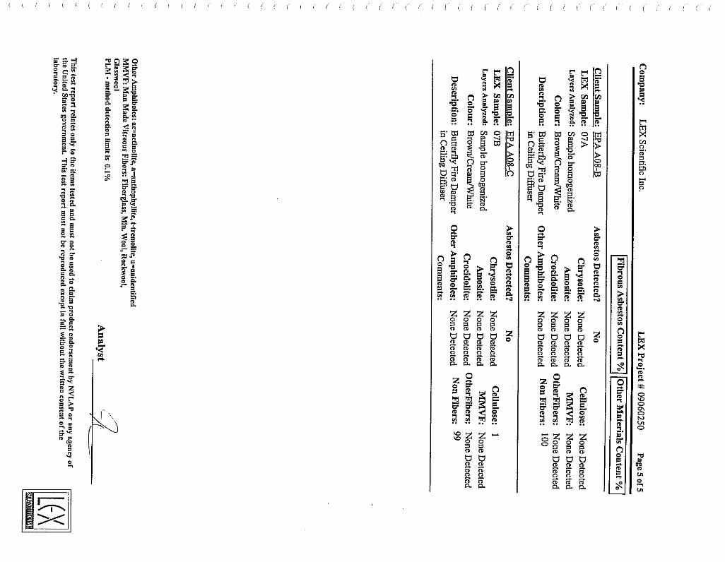
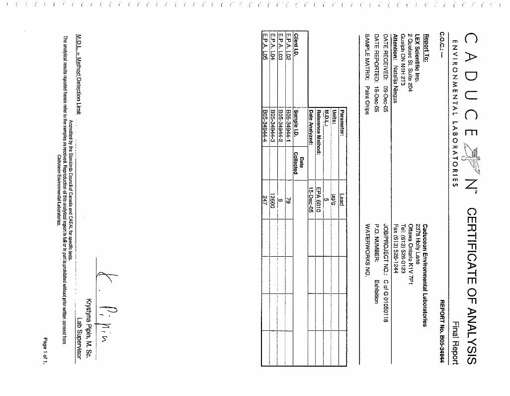
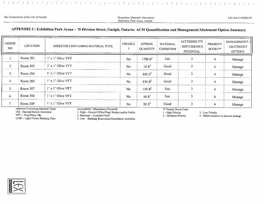
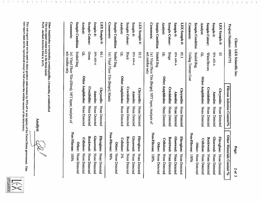
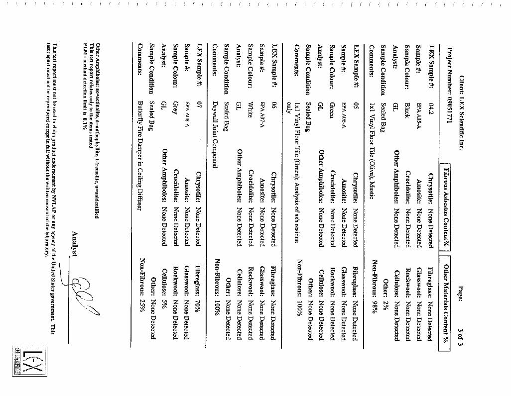
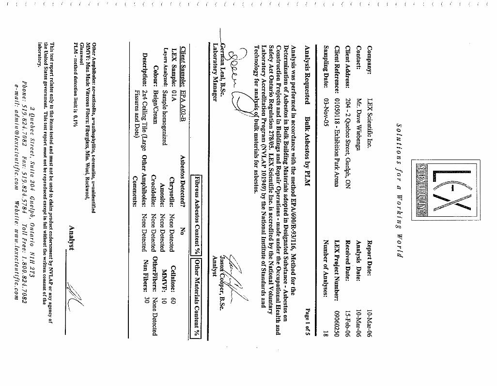
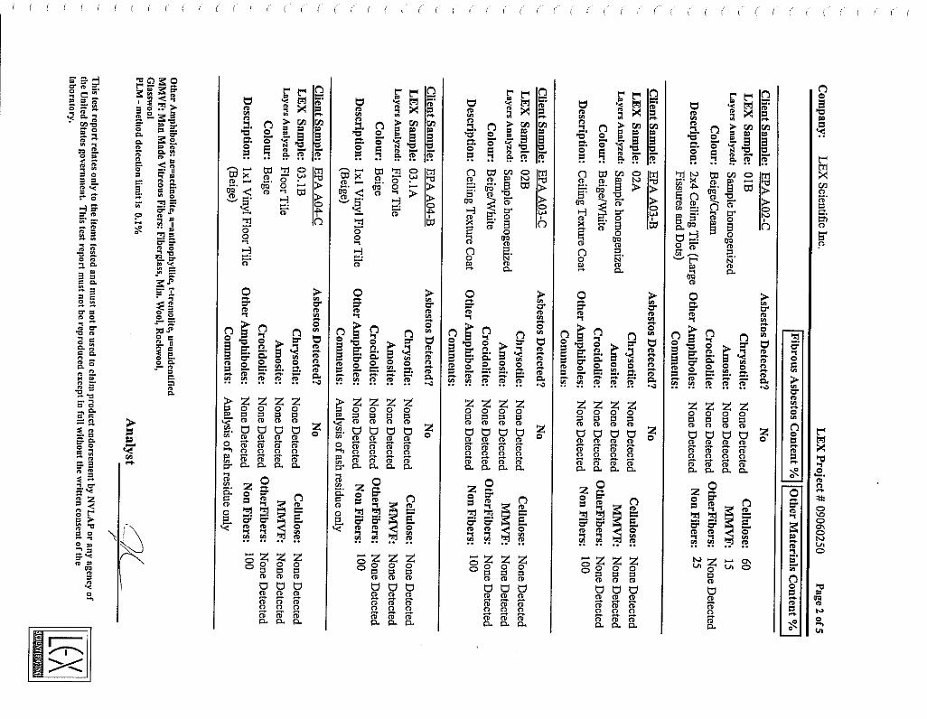
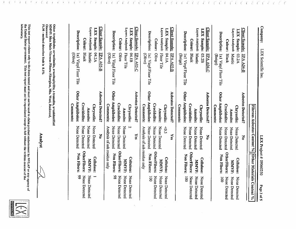
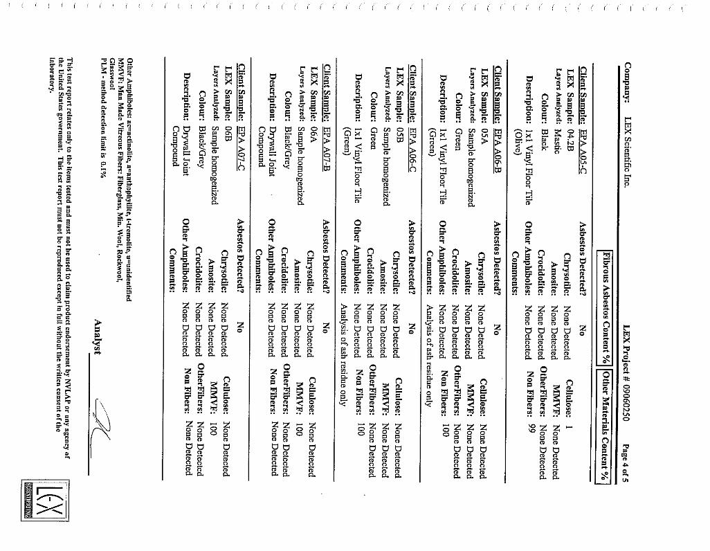
1.9 ASBESTOS .1 The City has completed a study of the facility and determined that there is no asbestos in the area. A
copy of that report can be made available to the Contractor if requested.
1.10 ALTERATION TO EXISTING .1 Prior to removal and alteration of the existing mechanical systems, the contractor shall identify to the
Engineer at which sections of the existing mechanical equipment and piping shall be cut back and removed.
.2 Relocate existing mechanical equipment and appurtenances as required to suit alteration work, or as specifically indicated on drawings or specified herein. Clean relocated equipment and install in new location, in a neat orderly manner with same attention as given to new equipment.
.3 Obtain written authorization from Engineer for alteration work that is not specifically called for under "Execution" or clearly indicated on drawings.
.4 Where existing material or equipment is damaged during execution of the Work, make good to satisfaction of the Engineer or replace with equivalent new equipment or materials as approved by the Engineer.
.5 When existing material or equipment is disconnected or disassembled to facilitate relocation, reinstall as original, including auxiliary work, piping, valves, gauges, insulation, electrical work, etc.
.6 Where equipment or material is found to be damaged or in an unsuitable condition, notify Engineer for instructions.
.7 Existing mechanical equipment shall be removed to suit new construction and alteration work as indicated on drawings.
.8 Materials removed by this Division shall become Contractor's property and be removed from work site, provided: .1 The item(s) have been inspected by the Owner and released for removal. .2 Item(s) have not been designated for reuse in other sections of specifications or drawings.
1.11 REMOVAL OF EXISTING EQUIPMENT .1 Examine the existing building and include in tender price all necessary moneys to remove and legally
dispose of existing equipment as detailed on drawings and specifications.
1.12 PROTECTION OF OPENINGS .1 Protect equipment and system openings from dirt, dust, and other foreign materials.
Efficiency Engineering Inc. Jan-11 Section 15010 Page 17 of 67
.2 The Contractor shall protect finished and unfinished work of his own and other subcontractors from damage due to carrying out the Work. The Contractor shall be responsible for the condition of all materials and equipment supplied under this contract or removed from existing building for reuse and shall provide all necessary protection for same. The Contractor shall be responsible for the protection and maintenance of the work of this section, until the building has been completed and accepted.
1.13 CUTTING AND PATCHING .1 All cutting of openings to walls, floors, roof, ceilings, plaster and drywall ceilings and any other
surfaces or finishes in the structure shall be the responsibility of the Contractor when related to any of the Work. The patching of finished assemblies restricted by the Work of this Division shall be performed by the affected (expert) trade at the expense of the Contractor.
.2 Under no circumstances shall any cutting or burning of the structural parts of the building be undertaken without the written authority of the Engineer.
.3 Work of this nature must comply with section 15080 – Cutting and Patching.
1.14 EQUIPMENT INSTALLATION .1 Unions or flanges: provide for ease of maintenance and disassembly. .2 Space for servicing, disassembly and removal of equipment and components: provide as
recommended by manufacturer or as indicated. .3 Equipment drains: pipe to floor drains .4 Install equipment parallel to or perpendicular to building lines. .5 Control panels, electrical panels and wiring termination points provide minimum 40" clearance.
1.15 ANCHOR BOLTS AND TEMPLATES .1 Supply anchor bolts and templates for installation by other divisions.
1.16 TRIAL USAGE .1 Obtain written permission from Engineer to start and test permanent equipment and systems to
acceptance by Owner. .2 Engineer and Owner may use equipment and systems for test purposes prior to acceptance. Supply
labour, material and instruments required for testing.
1.17 PIPE HANGERS AND SUPPORTS FOR STEEL PIPING .1 Upper attachments/inserts shall be suitable for application and building construction. .2 Middle attachment carbon steel threaded rod black. .3 Pipe attachment to suit pipe material, horizontal movement and rod length. .4 Hanger spacing:
Pipe Size, NPS Steel Rod Diameter
Maximum Spacing
up to 1-1/4 3/8" 7 ft. 1-1/2 3/8" 9 ft. 2 3/8" 10 ft. 2-1/2 3/8" 12 ft.
.5 Hanger Installation .1 Install hangers so that rod is vertical under operating conditions. .2 Adjust hangers to equalize load. .3 Support from structural members. Where structural bearing does not exist or inserts are not in
suitable locations, provide supplementary structural steel members.
Efficiency Engineering Inc. Jan-11 Section 15010 Page 18 of 67
1.18 PAINTING OF MECHANICAL WORK .1 Apply at least one coat of corrosion resistant primer paint to ferrous supports, site fabricated work and
uninsulated steel pipe for natural gas distribution. .2 Prime and touch up marred finished paint work to match original. .3 Restore to new condition damaged finishes on new materials.
1.19 DIELECTRIC COUPLINGS .1 Provide where pipes of dissimilar metals are joined. Shall be compatible with and to suit pressure
rating of piping system. .2 Pipes NPS 2 and under shall be with isolating unions. Pipes NPS 2½ and over shall be isolating
flanges. .3 Provide felt or rubber gaskets to prevent dissimilar metals contact.
1.20 DRAIN VALVES .1 Locate at low points and at section isolating valves unless otherwise specified. .2 Minimum NPS 3/4 unless otherwise specified: bronze, with hose end male thread and complete with
cap and chain.
1.21 DEMONSTRATION, OPERATION AND MAINTENANCE INSTRUCTIONS .1 Supply tools, equipment and personnel to demonstrate and instruct operating and maintenance
personnel in operating, controlling, adjusting, trouble-shooting and servicing of all systems and equipment during regular work hours, prior to acceptance.
.2 Manufacturers to provide demonstrations and instructions as specified in appropriate sections;
.3 Use O&M manual, as-built drawings, audio visual aids, etc as part of instruction materials.
.4 Instruction duration time requirements as specified in appropriate sections.
.5 Where deemed necessary by the Engineer demonstrations shall be recorded for future reference.
1.22 OPERATION AND MAINTENANCE MANUAL .1 Provide operation and maintenance data for incorporation into manual. .2 Operation and maintenance manual to be approved by, and final copies deposited with, the Engineer
before final inspection. .3 Operation data to include:
.1 Operation instructions for each system and each component.
.2 Description of actions to be taken in event of equipment failure.
.3 Valves schedule and flow diagram.
.4 Colour coding chart. .4 Maintenance data shall include:
.1 Servicing, maintenance, operation and trouble-shooting instructions for each item of equipment.
.2 Data to include schedules of tasks, frequency, tools required and task time. .5 Performance data to include:
.1 Equipment manufacturer's performance data sheets with point of operation as left after commissioning is complete.
.2 Equipment performance verification test results.
.3 Special performance data as specified elsewhere. .6 Approvals:
.1 Submit 2 copies of draft Operation and Maintenance Manual to Engineer for approval. Submission of individual data will not be accepted unless so directed by Engineer.
.2 Make changes as required and re-submit as directed by Engineer. .7 Additional data:
.1 Prepare and insert into operation and maintenance manual when need for same becomes apparent during demonstrations and instructions specified above.
1.23 CLEANING .1 Upon completion and in preparation for final acceptance, contractor shall remove protective coverings,
clean and refurbish all equipment, free all obstructions, clean strainers and leave in operating condition. All surplus and waste material shall be promptly removed from the premises.
END OF 15010
Efficiency Engineering Inc. Jan-11 Section 15030 Page 19 of 67
15030 – Record Drawings
1.0 GENERAL
1.1 PRINTS .1 The Engineer shall provide the Contractor with two complete sets of white prints to mark the project
progress, changes and deviations.
2.0 PRODUCTS
2.1 NOT USED
3.0 EXECUTION
3.1 DOCUMENTATION REQUIREMENTS .1 As the project progresses mark all changes and approved deviations from that shown on the drawings
to the white prints. .2 After inspection and approval of service lines in trenches, take as-built measurements, including all
depths, prior to commencement of backfilling operations. It will not be sufficient to check off line locations. Take and record definitive measurements for each service line. Show locations and inverts of buried piping on the drawings and dimensioned from grid co-ordinates. .1 Submit moisture penetration report and applicable drawing.
.3 Keep drawings up-to-date during construction and in addition to field measurements include change orders, site instructions and all other changes. Drawings shall be available for review at all times.
.4 On completion of the work, forward to the Engineer the two sets of drawings indicating all such changes and deviations for review.
.5 After the drawings have been reviewed, the Engineer shall transfer all as-built mark-ups from prints to math model using latest release of AutoCAD software.
.6 Final as-built prints/plots shall not contain markings or corrections by hand (i.e. marker, pen, pencil, etc.). Drawings containing mark-ups shall be revised re-printed/re-plotted.
.7 The project will remain incomplete and a holdback will be retained until satisfactory as-built information is provided.
3.2 FINAL DRAWINGS .1 The Engineer shall produce final drawings for the Owner of this project based on the information
submitted by the Contractor in the form of as-builts. .2 The Contractor is entitled to one (1) copy of final prints for their records. Additional copies may be
purchased for a price.
END OF 15030
Efficiency Engineering Inc. Jan-11 Section 15031 Page 20 of 67
15031 – Shop Drawings
1.0 GENERAL
1.0 GENERAL REQUIREMENTS .1 The GENERAL and SPECIAL CONDITIONS, Section 15010, are included as a part of this Section as
though written in full in this document.
2.0 PRODUCTS
2.1 SHOP DRAWINGS .1 Shop drawings shall be organized by specification section. Do not combine more than one section into
one submission. Incorrect submissions will be returned without review. .2 Shop drawings shall indicate clearly the materials and/or equipment actually being supplied, all details
of construction, accurate dimensions, capacity, operating characteristics and performance. Each shop drawings shall give the identifying number as noted in the documents of the specific pump, fan, etc. for which it was prepared.
.3 Each shop drawing for non-catalogue items shall be prepared specifically for this project. Shop drawings and brochures for catalogue items shall be marked clearly to show the items being supplied.
.4 When requested, shop drawings shall be supplemented by data explaining the theory of operation - for example: a variable speed motor control - the Engineer may also request that this information be added to the maintenance and operating manual.
.5 Provide a cover sheet with the project name, issue date, issue number, specification section number, title of section and with space for shop drawing review stamps from the Contractor and Engineer.
3.0 EXECUTION
3.1 SUBMISSIONS .1 Each shop drawing or catalogue sheet shall be stamped and signed by the Contractor to indicate that
he has checked the drawing for conformance with all requirements of the drawings and specifications, that he has co-ordinated this equipment with other equipment to which it is attached and/or connected and that he has verified all dimensions to ensure the proper installation of equipment within the available space and without interference with the work of other trades. Ensure that electrical co-ordination is complete before submitting drawings for review.
.2 Installation of any equipment shall not start until after final review of shop drawings by the Engineer has been obtained.
.3 Provide all necessary copies required for the trades, suppliers or other Engineers.
END OF 15031
Efficiency Engineering Inc. Jan-11 Section 15047 Page 21 of 67
15047 – Identification
1.0 GENERAL
1.1 SUMMARY .1 Section Includes: Identification including necessary accessories indicated on Construction Documents
and specified in this section or as required for proper identification of equipment and piping.
1.2 SUBMITTALS .1 Submit properly identified product and technical data including printed installation instructions before
starting work.
1.3 QUALITY ASSURANCE .1 Regulatory Requirements:
.1 Color Coding: ANSI Z535.1 (latest edition) shall take precedence over any discrepancies in determining proper color code identification.
.2 Conform to the standards established in ANSI A13.
.3 Comply with OSHA standards.
2.0 PRODUCTS
2.1 EQUIPMENT IDENTIFICATION .1 Identify equipment served by piping systems by number or legend as shown on Construction
Documents. .1 Provide identification for all components given an identifying code on Construction Documents. .2 Provide identification on all cabinets.
.2 Engraved Plastic Name Plates: Provide engraved laminated plastic name plates with 1 inch high letters on all equipment cabinets.
.3 Brass Tags: Provide 2" square brass tags on equipment where cabinets do not exist, stamped with ½" numbers and letters.
.4 Piping Identification conforming to ASME A13.1 scheme for the identification of pipes. 1. Color Coding: Identify piping with markers and directional arrows according to the following color
coding system: Description Background Letters Hot Water Yellow Black Cold Water Green White Gas Yellow Black Air Blue White Vacuum Green White Steam Yellow Black Nitrogen Green White Oxygen Yellow Black Hydrogen Yellow Black Refrigerant Yellow Black Fire Red White
.2 Piping Identification Materials: Identify contents and flow direction of piping or pipes wrapped with insulation by using: .1 Brady B-946 self-sticking vinyl. .2 Champion America Inc., pressure sensitive vinyl. .3 Seton Opti-Code. .4 Ready Made adhesive pipe markers.
.3 Identify flow direction using arrows on a roll tape, applied to wrap completely around the pipe .1 Apply arrows at each end of each pipe marker to add extra adhesion to the marker
Efficiency Engineering Inc. Jan-11 Section 15047 Page 22 of 67
2.2 VALVE IDENTIFICATION: .1 Identify location and system under valve control with a color coded thumb tack under valve on lay-in
ceiling tile. .2 Label each balancing valve with a waterproof plastic tag, showing ID code, dial setting, flow, and date
of balancing. Attach the tag securely with a tie-wrap or similar device capable of withstanding the temperatures that the valve will experience in operation.
.1 BURIED ELECTRICAL LINE BELOW - No.37236 by Seton. .2 2" Metallic Detection Tapes:
.1 BURIED SEWER LINE BELOW - No.37220 by Seton.
.2 BURIED WATER LINE BELOW - No.37222 by Seton.
3.0 EXECUTION
3.1 INSPECTION .1 Do not proceed with the work of this section until conditions detrimental to the proper and timely
completion of the work have been corrected in an acceptable manner. .2 Verify surfaces are clean and dry before application of identification signage.
3.2 INSTALLATION .1 Brass Tags or Engraved Plastic Name Plates:
.1 Install brass tags or engraved plastic name plates according to manufacturer's instructions. .1 Place brass tags or name plates in locations easily visible within the space at normal eye
level or as otherwise directed by A/E. .2 Piping Markers and Directional arrows:
.1 Location: .1 Pipes Passing through Walls: Provide pipe markers and directional arrows on the pipe on
each side of the wall. .2 Pipes behind Access Doors/Panels: Provide pipe markers and directional arrows within
view. .3 Continuous Run Pipe Lines: Provide pipe markers and directional arrows at intervals not
exceeding 50 feet. .4 Risers and "T" Joints: Provide pipe markers and directional arrows at each riser and "T"
joint. .5 Vertical and Horizontal Change of Direction: Provide pipe markers and directional arrows
at each vertical and horizontal change of direction. .2 Special Requirements:
.1 Directional Arrows: When identifying by directional arrows, point arrow head away from pipe markers and in the direction of flow. .1 Direction of Flow: If the flow can be in both directions, identify by using double
headed directional arrows. .2 Thin Film Pipe Markers and Thin Film Directional Arrows: When using both thin film pipe
markers and thin film directional arrows on soft insulation, provide a spiral wrap of accepted pipe banding tape around the pipe as foundation for both markers and directional arrows.
.3 Underground Tapes: .1 Electrical Warning Tape: Install warning tape 8 inches below finish grade on all underground
grade on all underground outside plumbing and air-conditioning lines.
END OF 15047
Efficiency Engineering Inc. Jan-11 Section 15056 Page 23 of 67
15056 – Nameplates
1.0 GENERAL
1.0 GENERAL REQUIREMENTS .1 The GENERAL and SPECIAL CONDITIONS, Section 15010 are included as a part of this Section as
though written in full in this document.
1.1 SCOPE OF WORK .1 Every piece of equipment shall have a nameplate. .2 Specification of nameplates covered in the Articles specifying particular equipment shall take
precedence over this Section.
1.3 SUBMITTALS .1 Submit samples of nameplates before installation.
2.0 PRODUCTS
2.1 NAMEPLATE MATERIALS .1 The nameplates shall be a minimum of 2 mm (3/32 in.) thick laminated phenolic plastic. Minimum size
shall be 100 mm (4 in.) long x 50 mm (2 in.) wide with maximum size to suit nomenclature required. .2 Nameplate shall be with black face and white centre and with 5 mm (7/32 in.) high lettering engraved
through to the white lamination .3 The nameplates shall have the equipment type and name as indicated in the equipment schedules. .4 The nameplates shall have the service and area of the building served (e.g. Chilled Water - South
Zone).
3.0 EXECUTION
3.1 INSTALLATION .1 Nameplates shall be securely fastened with screws or brass chains in a conspicuous place on the
equipment.
END OF 15056
Efficiency Engineering Inc. Jan-11 Section 15057 Page 24 of 67
15057 – Valve Tags and Charts
1.0 GENERAL
1.1 GENERAL REQUIREMENTS .1 The GENERAL and SPECIAL CONDITIONS, Section 15010, are included as a part of this Section as
though written in full in this document.
1.2 SUBMITTALS .1 Submit samples of charts and numbering system before installation.
2.0 PRODUCTS
2.1 VALVE TAGS .1 Tags shall be square colour coded phenolic with engraved numbers and/or letters as required. Tags
shall be a minimum of 25 mm (1 in.) square and maximum to suit numbering system. Numbers shall be nominally 9 mm (3/8 in.) high. Letters shall be nominally 6 mm (1/4 in.) high.
.2 Number and nameplates for standpipe and sprinkler system supervisory and main operating valves shall be minimum 2 mm (3/32 in.) thick laminated phenolic plastic and a minimum 125 mm (5 in.) long x 100 mm (4 in.) wide with red face and white centre. Lettering shall be a minimum 9 mm (3/8 in.) high with maximum to suit local authorities and shall be engraved through to the white lamination. Each nameplate shall contain the system name, service and valve number.
.3 For all other valves on standpipe and sprinkler system not required to have laminated number and nameplates, provide plastic tags as specified above.
.4 Abbreviations and colour code shall be as shown on Standard Details.
3.0 EXECUTION
3.1 INSTALLATION .1 Tags and nameplates shall be attached to the valve body or handle with brass hooks or chains. .2 All valves shall be provided with tags, other than valves on convectors, induction units or other space
heating, cooling units and valves on plumbing fixtures. Provide a chart or charts, indicating location, service and zone of each valve. This work shall be co-ordinated between the various Mechanical Sections to prevent overlapping of numbering systems.
.3 Provide separate charts for all fire system nameplates and tags.
.4 For extension and/or alterations to existing systems, provide new charts conforming in appearance to the existing charts.
.5 Co-ordinate valve identification with pipe and ductwork identification.
.6 Charts shall be set in metal picture frames with a clear acrylic front and fastened securely where directed by Engineer or Owner.
.7 All valve tag numbers for all systems shall be shown on the as-built drawings.
END OF 15057
Efficiency Engineering Inc. Jan-11 Section 15059 Page 25 of 67
15059 – Cleaning and Protection
PART 1 GENERAL
1.1 GENERAL REQUIREMENTS .1 The GENERAL and SPECIAL CONDITIONS, Section 15010, are included as a part of this Section as
though written in full in this document.
PART 2 PRODUCTS
2.1 NOT USED
PART 3 EXECUTION
3.1 INSTALLATION .1 Clean thoroughly all fixtures and equipment from grease, dirt, plaster or any other foreign material.
Chrome-plated fittings, piping and trim shall be polished upon completion. .2 Any dirt, rubbish, or grease on walls, floors or fixtures accumulated from the work shall be removed
promptly from the premises. .3 Fixtures and equipment shall be properly protected from damage during the construction period and
shall be cleaned and polished in accordance with manufacturer's directions. Motors and equipment bearings shall be protected with plastic sheets, tied or taped in place. Aluminum fin heating or cooling elements shall be protected with cardboard covers.
.4 Any unpainted steel surfaces, installed for longer than one year prior to the completion date, shall be prime coated.
.5 During construction protect all services and equipment from dirt and debris, by using temporary caps over the open ends of pipes, ductwork, and equipment connections.
.6 All equipment installed or stored on site shall be maintained in accordance with manufacturers recommended instructions (i.e. rotate shafts on fans, pumps, etc).
.7 Refinish and restore to the original condition and appearance all mechanical equipment which has sustained damage to the manufacturer's prime and finish coats of enamel or paint. Materials and workmanship shall be equal to the manufacturers original.
END OF 15059
Efficiency Engineering Inc. Jan-11 Section 15080 Page 26 of 67
15080 – Cutting and Patching
1.01 GENERAL
1.0 GENERAL REQUIREMENTS .1 The GENERAL and SPECIAL CONDITIONS, Section 15010, are included as a part of this Section as
though written in full in this document.
1.1 SCOPE OF WORK .1 Cutting and patching is required whenever services (wires, pipes, ducting, etc.) are required to pass
through an existing wall.
2.0 PRODUCTS
2.1 MATERIALS .1 All services and materials used for the cutting and patching shall be carried out by professional
workers experienced in the cutting and patching work to be done.
3.0 EXECUTION
3.1 INSTALLATION .1 Locate all openings in non structural elements requiring cutting and patching to avoid unnecessary
cutting. All openings shall be shown on Drawings and submitted to the Engineer for review. No holes through structure shall be permitted prior to review by the Engineer.
.2 Core drilling for individual services shall be by this Division. Cut all openings no larger than is required for the services.
.3 Locate all openings in structure elements requiring cutting and patching and x-ray the structure to obtain the Engineer’s approval prior to cutting or core drilling of existing structure. Make adjustments to location of openings as required to minimize cutting of rebar and completely avoid electrical conduit. .1 Cut holes through slabs only. .2 Do not cut holes through beams. .3 Holes to be cut are 200mm (8 in.) diameter or smaller only. .4 Maintain at least 100mm (4 in.) clear from all beam faces. Space at least 3 hole diameters on
Centre. .5 For holes that are required closer than 25% of slab span from the supporting beam face, use
cover meter above the slab to clear slab top bars. .6 For holes that are required within 50% of slab span, use cover meter underside of slab to clear
slab bottom bars. .7 X-rays shall be performed by a qualified technician, in a safe manner and in accordance with
all applicable regulations governing this activity. .4 Obtain written approval from the structural Engineer before cutting or core drilling any openings or
holes. .5 Patch all openings after services have been installed to match the surrounding finishes.
END OF 15080
Efficiency Engineering Inc. Jan-11 Section 15094 Page 27 of 67
15094 – Hangers and Supports
1.0 GENERAL .1 The GENERAL and SPECIAL CONDITIONS, Section 15010 are included as a part of this Section as
though written in full in this document.
1.1 SCOPE OF WORK .1 Piping and equipment provided under the Mechanical Division shall be complete with all necessary
supports and hangers required for a safe and workmanlike installation. .2 Hangers, supports, anchors, guides, and restraints shall be selected to withstand all static and
dynamic loading conditions which act upon the piping system and associated equipment. The Mechanical Division shall prepare detailed shop drawings showing all anchors and guides for all systems with the potential for thermal expansion/contraction and/or loads due to weight or thrust. The drawings shall bear the signed seal of a Professional Engineer licensed to practice in the appropriate discipline and place of work. The drawings shall include all details of construction, static and dynamic forces at points of attachment, etc. necessary for review and acceptance by the project Structural Engineer. Make adjustments as necessary to satisfy the requirements of the Structural Division. No anchor points shall be permitted without reviewed shop drawings and, where installed prior to review, shall be removed and replaced to the satisfaction of the Engineer.
2.0 PRODUCTS
2.1 HANGERS AND SUPPORTS .1 Provide hangers and supports manufactured by Anvil International or E. Myatt & Co. .2 All pipe hangers and supports shall be manufactured to the latest requirements of MSS-SP- 58.
Where applicable, design and manufacture of hangers and supports shall also conform to ANSI/ASME Code for Pressure Piping B31.1.
.3 Pipe rolls shall have cast iron rollers, shaped to accept the outside diameter of the insulated pipe. Roll shall either rotate on a steel shaft mounted on a cast iron stand or shall roll on a cast iron bed plate.
.4 Roof supports for duct runs greater than 30 ft. shall be Thaler Roof Specialties.
.5 Roof supports for duct runs less than 30 ft. shall be Thaler Roof Specialties or Portable Pipe Hangers Inc.
.6 Roof supports for pipe runs shall be Thaler Roof Specialties or ABI (A Better Idea) premade rubber-coated roof blocks.
.7 All hangers, supports, brackets and other devices installed exterior to the building shall be galvanized to prevent failure from environmental corrosion. If galvanized components cannot be used submit samples of proposed substitute for review prior to installation.
3.0 EXECUTION
3.1 INSTALLATION .1 Pipe hangers shall be capable of supporting the pipe in all conditions of operation. They shall allow
free expansion and contraction of the piping. .2 Piping shall be supported from walls, beams, columns, and slabs using approved structural
attachments. In situations where approved attachments cannot be used, alternative attachments or substructure assemblies shall receive approval prior to installation. Prior approval shall be given for any cutting or drilling of building structural steel. Damage or modification to the structure through welding, cutting, or drilling shall not be permitted if it reduces the integrity of the building structure as deemed by the Structural Engineer. It shall be the responsibility of the Mechanical Division to supply anchor bolts and base diagrams for equipment and pipe supports showing exact location of attachments.
.3 All drilling for hangers, rod inserts and work of similar nature shall be done by this Division.
.4 Auxiliary structural members shall be provided under the Mechanical Section concerned where piping, ducts or equipment must be suspended between the joists or beams of the structure, or where required to replace individual hanger to allow for installation on new services. Submit details for review as requested.
.5 Depending on the type of structure, hangers shall be either clamped to steel beams or joists, or attached to approved concrete inserts. Submit proposed hanger details for review and acceptance by
Efficiency Engineering Inc. Jan-11 Section 15094 Page 28 of 67
the Structural Engineer. Make adjustments as necessary to satisfy the requirements of the Structural Division.
.6 Approved type expansion shields and bolts may be used for pipe up to 100 mm (4 in.) diameter where the presetting of concrete inserts is not practical. Submit proposed hanger details for review and acceptance by the Structural Engineer. Make adjustments as necessary to satisfy the requirements of the Structural Division.
.7 Suspension from metal deck shall not be allowed unless specifically accepted by the Engineer. Drawings of the proposed method of suspension must be submitted for review.
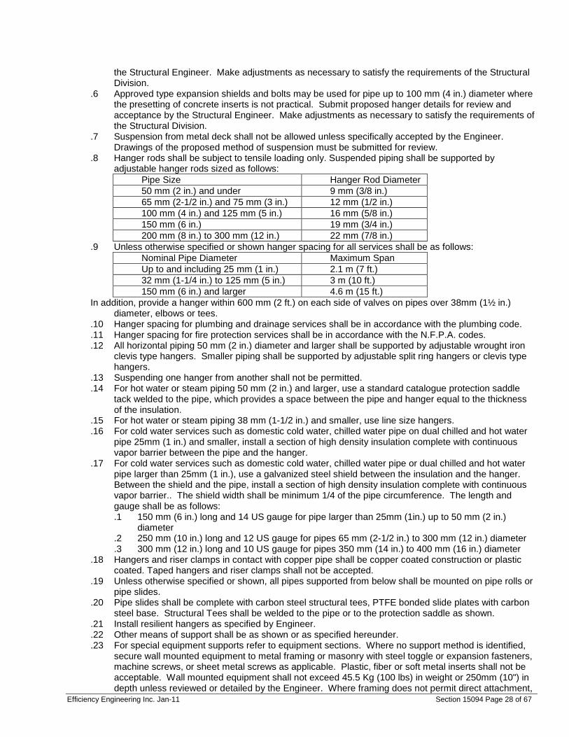
.8 Hanger rods shall be subject to tensile loading only. Suspended piping shall be supported by adjustable hanger rods sized as follows:
Pipe Size Hanger Rod Diameter 50 mm (2 in.) and under 9 mm (3/8 in.) 65 mm (2-1/2 in.) and 75 mm (3 in.) 12 mm (1/2 in.) 100 mm (4 in.) and 125 mm (5 in.) 16 mm (5/8 in.) 150 mm (6 in.) 19 mm (3/4 in.) 200 mm (8 in.) to 300 mm (12 in.) 22 mm (7/8 in.)
.9 Unless otherwise specified or shown hanger spacing for all services shall be as follows: Nominal Pipe Diameter Maximum Span Up to and including 25 mm (1 in.) 2.1 m (7 ft.) 32 mm (1-1/4 in.) to 125 mm (5 in.) 3 m (10 ft.) 150 mm (6 in.) and larger 4.6 m (15 ft.)
In addition, provide a hanger within 600 mm (2 ft.) on each side of valves on pipes over 38mm (1½ in.) diameter, elbows or tees.
.10 Hanger spacing for plumbing and drainage services shall be in accordance with the plumbing code.
.11 Hanger spacing for fire protection services shall be in accordance with the N.F.P.A. codes.
.12 All horizontal piping 50 mm (2 in.) diameter and larger shall be supported by adjustable wrought iron clevis type hangers. Smaller piping shall be supported by adjustable split ring hangers or clevis type hangers.
.13 Suspending one hanger from another shall not be permitted.
.14 For hot water or steam piping 50 mm (2 in.) and larger, use a standard catalogue protection saddle tack welded to the pipe, which provides a space between the pipe and hanger equal to the thickness of the insulation.
.15 For hot water or steam piping 38 mm (1-1/2 in.) and smaller, use line size hangers.
.16 For cold water services such as domestic cold water, chilled water pipe on dual chilled and hot water pipe 25mm (1 in.) and smaller, install a section of high density insulation complete with continuous vapor barrier between the pipe and the hanger.
.17 For cold water services such as domestic cold water, chilled water pipe or dual chilled and hot water pipe larger than 25mm (1 in.), use a galvanized steel shield between the insulation and the hanger. Between the shield and the pipe, install a section of high density insulation complete with continuous vapor barrier.. The shield width shall be minimum 1/4 of the pipe circumference. The length and gauge shall be as follows: .1 150 mm (6 in.) long and 14 US gauge for pipe larger than 25mm (1in.) up to 50 mm (2 in.)
diameter .2 250 mm (10 in.) long and 12 US gauge for pipes 65 mm (2-1/2 in.) to 300 mm (12 in.) diameter .3 300 mm (12 in.) long and 10 US gauge for pipes 350 mm (14 in.) to 400 mm (16 in.) diameter
.18 Hangers and riser clamps in contact with copper pipe shall be copper coated construction or plastic coated. Taped hangers and riser clamps shall not be accepted.
.19 Unless otherwise specified or shown, all pipes supported from below shall be mounted on pipe rolls or pipe slides.
.20 Pipe slides shall be complete with carbon steel structural tees, PTFE bonded slide plates with carbon steel base. Structural Tees shall be welded to the pipe or to the protection saddle as shown.
.21 Install resilient hangers as specified by Engineer.
.22 Other means of support shall be as shown or as specified hereunder.
.23 For special equipment supports refer to equipment sections. Where no support method is identified, secure wall mounted equipment to metal framing or masonry with steel toggle or expansion fasteners, machine screws, or sheet metal screws as applicable. Plastic, fiber or soft metal inserts shall not be acceptable. Wall mounted equipment shall not exceed 45.5 Kg (100 lbs) in weight or 250mm (10") in depth unless reviewed or detailed by the Engineer. Where framing does not permit direct attachment,
Efficiency Engineering Inc. Jan-11 Section 15094 Page 29 of 67
provide metal strut sub-framing or minimum 19mm (3/4 in.) fire retardant treated plywood backboards, unpainted, attached to the framing. Provide attachments for backboards at 600 mm (24 in.) on centres with no less than 4 attachments.
END OF 15094
Efficiency Engineering Inc. Jan-11 Section 15169 Page 30 of 67
15169 – Indicating Instruments
1.0 GENERAL .1 The GENERAL and SPECIAL CONDITIONS, Section 15010, are included as a part of this Section as
though written in full in this document.
1.1 SUBMITTALS .1 Shop Drawings: Further to requirements of Section 15010, submit working ranges of thermometers
and gauges with shop drawings.
2.0 PRODUCTS
2.1 MATERIALS .1 Pipeline thermometers shall be complete with:
.1 Dust-tight stainless case and stem with 127 mm (5 in.) dial.
.2 Bi-metal type.
.3 White face with black lettering
.4 Range normally 0 to 115 deg. C. (32 to 240 deg. F.) for hot water and -17 to 49 deg. C. (0 to 120 deg. F.) for chilled water but range shall suit maximum and minimum temperatures of location and be shown on shop drawings.
.5 Temperature marking in 1 deg. C. (2 deg. F.) increments in both imperial and metric scales.
.6 External recalibration adjustment.
.7 Separable socket with extension neck as required for insulated pipe.
.8 Universal adjustable hinge
.9 Wells shall be registered with the provincial Boiler and Pressure Vessel Safety Branch and have a C.R.N. registration number.
.2 Pressure gauges shall be complete with: .1 Dust-tight nominal 115 mm (4-1/2 in.) dia. case, solid front complete with back blow-out to
A.N.S.I. B40-1 Grade 2A Level Standards. .2 Back-flanged where required. .3 Black pointer .4 White dial with black markings .5 Dial range to cover twice the average working pressure of the equipment and shall be compound
gauges on pump suction for all open systems. .6 Clear lens .7 Phosphor bronze bourdon tube, silver soldered. .8 Brass or stainless steel movement, bronze or nylon brushed, scale and movement mounted
independent of the case. .9 Brass socket .10 kPa and psi scales .11 Provincial Boiler and Pressure Vessel Safety Branches registration number
.3 Manometers shall be Magnahelic gauge type in dust free case with black pointer. Gauge range shall be 2-1/2 times the maximum filter resistance. Case shall be suitable for duct or plenum mounting. Provide bracket for mounting gauge on insulated ducts or plenums.
.4 Thermometers shall be Trerice, Taylor, Weksler, Winters or Ashcroft.
.5 Pressure gauges shall be Trerice, Ashcroft, Morrison, Winters or Weksler.
.6 Manometers shall be Airflow Developments or Dwyer.
Efficiency Engineering Inc. Jan-11 Section 15169 Page 31 of 67
3.0 EXECUTION
3.1 INSTALLATION .1 Locate all thermometers and pressure gauges so as to assure easy reading from the floor or platform. .2 Where direct reading instruments cannot be satisfactorily located use a remote instrument. .3 Locate remote instruments next to the point of the reading, on wall or structure. .4 Each remote or panel mounted instrument shall have an engraved lamacoid nameplate identifying the
system and service. .5 Insert pipeline thermometer into tanks, equipment tapings or in pipeline using screwed tees or forged
steel couplings, welded into the lines. .6 Insert pressure gauges into equipment tapings or in pipelines using screwed tees or forged steel
couplings welded into the lines. .7 Provide thermometers in the following locations in pipelines:
.1 In and out of each water coil or other coil, handling liquid, except individual reheat coils in ductwork.
.2 On each branch of 3 port control valves, excluding valves on fan coil, induction units, or individual reheat coils in ductwork.
.3 In and out of each heat exchanger, condenser, cooler or type of other heat exchanger.
.4 Each heating water return and each heating water supply for each main system
.5 Each hot or cold water storage tank
.6 And where specifically shown .8 When a common supply header provides the same temperature water to many coils or to many zones,
provide a thermometer on the common header only, rather than a thermometer on each branch. .9 For control valves with by-pass located thermometer in common pipe to allow for manual temperature
control. .10 Provide test wells for thermometers where shown. Test wells shall be compatible with the
thermometers used. Wells shall be registered with the Provincial Boiler and Pressure Vessel Safety Branch and have a C.R.N. registration number.
.11 Provide a Watts B6000 ball valve on the inlet to each gauge. In addition, install a coil siphon on each steam gauge. Install a pressure snubber on any gauge installed near a pump or in any location where damping is required to prevent rapid oscillation of the pointer. When the equipment is subject to vibration, mount the gauge on adjacent wall or on a mounting plate, supported from the floor.
.12 Provide pressure gauges in the following areas: .1 City water line where it enters the building .2 In and out of each pump .3 In and out of all pressure reducing valves .4 On each steam, hot water supply and hot water return header .5 Air cushion tank or expansion tank .6 City water make-up line .7 In and out of each heat exchanger, condenser, cooler or type of other heat exchanger .8 And where specifically shown
.13 Valve connections for pressure gauges shall be installed on each side of coils.
.14 Install manometer at each bank of filters to show the resistance to air flow through the filters. Where pre-filters and final filters are mounted in a common frame it is only necessary to provide a single manometer to show the resistance across the total filter assembly. Where filters are separately mounted in individual frames provide a manometer for each set of filters.
END OF 15169
Efficiency Engineering Inc. Jan-11 Section 15780 Page 32 of 67
15780 – Variable Frequency Drives for Fans and Pumps
1.0 GENERAL REQUIREMENTS .1 The GENERAL and SPECIAL CONDITIONS, Section 16010, are included as a part of this Section as
though written in full in this document.
1.1 SCOPE OF WORK .1 The Contractor shall supply, install, program, and commission variable frequency drives (VFDs) on
fans or pumps as indicated. .2 The Contractor shall replace the existing motors.
1.4 REFERENCES .1 Ontario Building Code .2 Ontario Electrical Safety Code .3 Ontario Ministry of Labour .4 Canadian Standards Association .5 Local Electrical Authority .6 All other Codes, Standards, and Regulations referred to in the above documents, adopted by the
authorities having jurisdiction and/or applicable to the work of this Section.
and size of field connections. .2 Submit product data indicating capacities, weights, specialties and accessories, electrical
requirements, and wiring diagram, .3 Submit schedule of equipment typically indicating sizes and number of units, including capacity data. .4 Submit Manufacturer’s Installation Instructions. Indicate rigging, assembly, and installation
instructions.
1.6 OPERATION AND MAINTENANCE DATA .1 Submit operation and maintenance data .2 Include manufacturer’s descriptive literature, operating instructions, maintenance instructions, and unit
parts. .3 Upon completion of the installation, supply three complete sets of service and maintenance manuals
including wiring and connection diagrams.
1.7 WARRANTY .1 Provide a 24-month parts and labor warranty on all components.
2.0 PRODUCTS
2.1 INVERTER-DUTY MOTOR .1 Approved Manufacturers:
General Electric Westinghouse Leeson Baldor
.2 The motor shall be a high efficiency, inverter duty, TEFC motor. The motor shall match the existing motor in every other manner, including voltage, horsepower, service factor, frame size, synchronous speed, etc.
.3 CSA Certified
Efficiency Engineering Inc. Jan-11 Section 15780 Page 33 of 67
2.2 VARIABLE FREQUENCY DRIVE .1 Approved Manufacturers:
ABB Danfoss-Graham
.2 ELECTRICAL RATING – As indicated. The VFD shall be capable of operating with input voltage variations of ±10% and input frequency variations of ±5%.
.3 OVERLOAD CAPACITY – The VFD shall have a current overload capacity (in variable torque mode) of 120% for 60 seconds and 180% for peak.
.4 DRIVE EFFICIENCY – The VFD shall have a drive efficiency above 96% at full load and a drive efficiency above 93% over the entire range of operating speeds.
.5 POWER FACTOR – The VFD shall have a displacement power factor greater than 0.97.
.6 OUTPUT FREQUENCY – The VFD shall have an output frequency range of 5 Hz to 75 Hz with an accuracy of ±1%. The VFD shall be programmed to limit the output frequency to 60 Hz to prevent inadvertent high speed operation. The VFD shall have 2 selectable critical frequency rejection points with adjustable bands.
.7 AUTO RESTART – The VFD shall have a selectable auto restart after momentary power loss.
.8 HARMONICS – The VFD shall operate with a voltage total harmonic distortion (THD) of less than 5% over the entire Output Frequency. Other electrical devices (line reactors, isolation transformers, etc.) shall be installed as required to bring the THD to below 5%.
.9 CONTROL PANEL – The VFD shall have an LCD alpha/numeric display with keypad. The control panel shall be capable of displaying the following in a clear manner: .1 Speed in percent (%), electrical frequency (Hz) and motor RPM. .2 Output frequency, voltage, current and torque. .3 Input voltage and power. .4 Values of all input and output signals.
.10 VOLTS / HERTZ RATIO – The Volts / Hertz (V/Hz) ratio pattern, which dictates the torque variability over the motor speed range, shall be programmable over the entire frequency range.
.11 CONTROL INTERFACE: .1 ANALOG INPUT – The VFD shall be capable of receiving an analog-in (AI) signal (the signal
may be either 0-10 V or 4-20 mA). The VFD shall be programmable to control the motor speed using the AI signal and PID controls.
.2 DIGITAL INPUT – The VFD shall be capable of starting and stopping the motor based on a DI (dry contact) signal.
.3 ANALOG OUTPUT – The VFD shall be capable of sending an analog-out (AO) signal (either 0-10 V or 4-20 mA) indicating the motor speed.
.4 DIGITAL OUTPUT – The VFD shall be capable of sending a digital-out (DO) signal indicating the drive status.
.5 COMMUNICATION BUS INTERFACE – The VFD shall be supplied with a bidirectional BACnet or LonWorks interface for communication bus connection, compliant with the standard specified in Section 15920.
.12 PROTECTIVE FEATURES .1 ENCLOSURE – The VFD shall be enclosed in NEMA enclosure with a rating suitable to the drive
location. .2 MOTOR STARTING – The VFD shall be capable of starting a rotating motor (either forwards or
backwards) without any damage to the motor or drive. .3 AMBIENT CONDITIONS – The VFD shall be capable of operating, without damage, in ambient
temperatures of –10°C to 40°C with relative humidity up to 95%. .4 MOTOR PROTECTION – The VFD shall be designed, installed and programmed to minimize
any harmful effects such as voltage reflection, voltage spikes, etc. .5 TEST OPERATION - The drive shall be capable of running without a motor connected for setup
and testing. .6 FREQUENCY REJECTION POINTS - The drive shall be programmable with up to three
frequency rejection points to prevent the pump from operating at a resonant speed. Both the centre frequencies and the band widths shall be adjustable.
Efficiency Engineering Inc. Jan-11 Section 15780 Page 34 of 67
.7 THERMISTOR RELAY - Provide a thermistor relay for the motor. If the relay is activated due to a motor over temperature condition, the VFD shall shut down and register a "Motor Over temperature" alarm.
2.3 VFD BYPASS .1 Where indicated, provide a manual bypass panel sized for the application to provide power directly to
the motor in the event of VFD or control failure. .2 Nema 2 enclosure with a three-position "Bypass / Off / VFD" switch mounted on the face. .3 Complete with local fused disconnect switch.
2.4 FUSES .1 For VFD’s without bypass, use Gould A4J fast-acting fuses or equivalent, sized for the motor. .2 Select fuses for each application, with proper dimensions for existing fuse clips within MCC or local
starter, and sized for electrical load. .3 For VFD’s with bypass, use Gould Type J time delayed fuses or equivalent, sized for the motor.
3.0 EXECUTION
3.1 INSTALLATION .1 The VFD and motor shall be installed as recommended by the VFD manufacturer and shall meet all
applicable codes. .1 Use TECK-90 cable into and out of VFDs
.1 Power conductors plus ground, within a continuous metal jacket.
.2 Waterproof black PVC outer jacket.
3.2 LOCATION .1 The VFD shall be wall or base mounted as close to the motor as practical, at approximately 60" height,
taking into account RFI, EMI and temperature concerns. The VFD shall not be installed in an MCC panel. The cable length between the VFD and the motor shall not exceed 25 feet. If the cable length is more than 25 feet, dv/dt filters shall be installed where voltage reflection may occur. The cable shall be installed so that it is not a tripping hazard.
.2 Install bypass and fused disconnect on the same structural surface as the VFD, at a similar height, and as close as practical to the VFD enclosure without restricting cooling air flow.
.3 Make connections as per manufacturer’s wiring instructions.
3.3 REMOVAL OF EXISTING INLET OR OUTLET THROTTLING .1 Pumps. Remove and dispose of any existing inlet or outlet throttling devices and associated controls
in a safe and legal manner. .1 Piping shall be adapted as necessary and to a standard equal to the surrounding pipe work and
as detailed elsewhere in this specification. Insulation shall be as detailed elsewhere in this specification.
.2 Fans. Remove and dispose of any existing fan inlet vanes or outlet flow control dampers in a safe and legal manner. .1 Patch ductwork and insulation to a standard equal to the surrounding ductwork and as detailed
elsewhere in this specification.
3.5 VFD AND MOTOR INITIAL STARTUP AND TESTING .1 The equipment supplier will provide VFD and motor startup by a Certified Drive Manufacturer’s
Technician. Coordinate with the supplier to ensure that all requirements are included at startup. .2 Documentation
.1 Provide a documented startup form for every drive, to register the warranty with the manufacturer.
.2 Provide the Owner with startup and commissioning documentation in paper form and also in electronic form on CD-ROM.
.3 Set the speed of the VFD to respond in a linear fashion to the output signal from the building automation system. The V/Hz ratio shall be set at either squared or automatic. The V/Hz ratio shall be as low as possible while still allowing correct equipment operation.
Efficiency Engineering Inc. Jan-11 Section 15780 Page 35 of 67
.1 The drive operating speed ranges shall be set from 30Hz to 60Hz for a full input control signal range.
.4 The VFD / motor combination shall be tested over the output frequency range (up to 60 Hz). Critical frequency rejection points and bands shall be set up for any frequencies that cause instabilities in the fan or pump operation or excessive vibration in the fan or pump housing. .1 Ensure that VFDs and motors are tested under full load.
.1 For fan applications, this may involve building staff adjusting controls on variable volume boxes to ensure that the boxes open to full air flow.
.2 For pump applications, this may involve building staff adjusting central heating or cooling controls to allow flow control valves in the distribution system to open fully.
.5 Make the following control connections functional and available for the Controls Contractor, and coordinate with the Controls Contractor with respect to specific interface requirements: .1 Analog input to set voltage frequency to motor (drive speed). .3 Digital output indicating drive status.
.1 Set the status point so that a loss of power to the VFD (including bypass operating mode) indicates an alarm condition.
.4 Digital input for start/enable of VFD.
3.6 WARRANTY .1 The VFD / motor combination and installation warranty shall be for 24 months from the date of certified
start-up. The warranty shall include all parts, labour, travel time and expenses. The warranty shall include the installation of any power quality correction devices (line reactors, dv/dt filters, etc.) that may be necessary to bring the THD to an acceptable level (as defined above).
END OF 15780
Efficiency Engineering Inc. Jan-11 Section 16010 Page 36 of 67
16010 – Electrical General Requirements
1.0 GENERAL .1 This specification, along with the provided drawings, covers the materials, labour and other services to
complete the electrical installation for the project. 1.1 GENERAL WORK INCLUDED .1 Supply and install all wiring, materials, equipment, etc., shown or required unless otherwise specified.
Any item or system which is shown, mentioned or reasonably implied on either the drawings or in the specifications shall be considered to be properly and sufficiently specified and shown, and must be provided. Include all labour, equipment, tools, etc., required to complete all installations as intended. Install all equipment according to the method indicated, manufacturer's instructions and according to standard industry practices.
.2 During the course of construction and testing, contractor shall report any equipment that fails to
operate correctly, is damaged, or is in a condition that will not allow it to last for another 5 years. Contractor must provide, on request, a time and material estimate to repair or replace the faulty equipment. No additional work shall be undertaken without an estimate and approval in writing by the Engineer and the Owner.
.3 Cables shall be installed as per manufacturer’s guidelines. Only proper pulling equipment shall be
utilized. Minimum bending radii and cable pulling tension shall not be exceeded. Ducts and cables shall be neatly trained in trenches and shall be adequately supported. Contractor shall decide means and set-up of pulling equipment and direction of pull. Plan to be reviewed with Engineer prior to set-up.
.4 All test and installation equipment shall be operated safely using the procedures outlined in the
manufacturer’s operating manual. Only personnel trained and qualified to operate the equipment shall perform this work.
.5 The contractor shall be responsible for all permits, locates and inspections necessary to successfully
perform the work. The contractor will pay for all associated costs of the above and include these costs in his proposal.
1.2 SCOPE OF WORK .1 The following outlines the scope of work of the project. Details regarding materials and installation
methods are covered in the accompanying specifications. The drawings included in the package show the general layout of the work and include details regarding the installation.
.1 Installation of new evaporative condenser in place of existing on panel; .2 Installation of new evaporative condenser pump in place of existing on panel;
.2 The Contractor shall be responsible for receiving, handling, storage, installation, and connection of the
all of the equipment.
Efficiency Engineering Inc. Jan-11 Section 16010 Page 37 of 67
.3. The Contractor shall be responsible for: .1. Complete systems in accordance with the intent of these Contract Documents. .2. Coordinating the details of facility equipment and construction for all Specification Divisions which affect the work covered under this Division. .3 Furnishing and installing all incidental items not actually shown or specified, but which are required by good practice to provide complete functional systems. 1.3 DESIGN REQUIREMENTS .1 Equipment and devices to be installed outdoors or in unheated enclosures shall be capable of
continuous operation within an ambient temperature of -25 to +40 degrees C. .2 Compliance by the Contractor with the provisions of this Specification does not relieve him of the
responsibilities of furnishing equipment and materials of proper design, mechanically and electrically suited to meet operating guarantees at the specified service conditions.
.3. All electrical components shall be CSA listed and labeled. 1.4 SUBMITTALS .1 Submittals shall be made in accordance with the provisions of Section 01300, Submittals, and the
requirements of this Section. .2 Include inspection and permit certificates and certificates of final inspection and acceptance from the
authority having jurisdiction. .3 Manufacturer's standardized schematic diagrams and catalog cuts shall not be acceptable unless
applicable portions of same are clearly indicated and non-applicable portions clearly deleted or crossed out.
1.5 RULES, REGULATIONS, AND PERMITS .1 Provide all work and materials in accordance with the latest editions of the Ontario Electrical Safety
Code, the Ontario Building Code, The Ontario Health and Safety Act, any applicable CSA Standards, the requirements of the Electrical Safety Authority, and all other applicable Municipal and Provincial codes and regulations. Any materials, equipment or installations not meeting all requirements of the appropriate regulatory agencies will not be accepted. It is the Contractor's responsibility to ensure these requirements are met and provide evidence of such.
.2 Contractor shall obtain and pay for all permits and fees for the execution and inspection of the
electrical work. All work shall be provided by qualified journeyman electricians or apprentices holding valid Ontario Certificates of Qualification and be supervised by a competent foreman. The contractor shall also be a registered Master Electrician if such is required in the particular municipality where the work is performed. Certificates verifying that the installation and equipment meets all applicable inspections shall be presented to the Engineer.
.3 The Contractor is obliged to inform the Engineer immediately of any contradiction or omission in the
specifications or drawings relating to conformance with the aforementioned codes and standards so that it can be corrected prior to tender closing. Failure to do so will not relieve the Contractor from meeting the intent of paragraph 1.06, A.
.4 Provide all necessary grounding as required by Electrical Safety Authority regardless of whether it is
shown on the drawings. .5 All necessary cutting and patching for the electrical work will be provided by the appropriate skilled sub
trade with at least 5 years skill-specific experience at the expense of the Contractor. Holes through
Efficiency Engineering Inc. Jan-11 Section 16010 Page 38 of 67
exterior walls are to be flashed and made weatherproof. Repair any damage caused by the Contractor to existing buildings, equipment, or grounds, etc., to the satisfaction of the Engineer, The Owner. Upon completion of the work, clean all equipment and remove from the site all debris associated with the work of all trades.
.6 Provide legible signs and barriers on or around all live panels and test equipment during construction
and testing to prevent injury or shock. .7 Test all equipment and wiring at any time requested by the Engineer as part of the Contract. Provide
all meters, materials and qualified personnel required to perform this work. .8 The Contractor and all associated sub trades must carry proper and adequate liability insurance to
protect all affected parties including the Owner and the Engineer from all claims related to their work for this project.
.9 Perform all work in such a manner as to cause as little disturbance or inconvenience as possible to the
existing operations of the owner. Ensure that all outages are coordinated with the Owner’s designated representative. Provide temporary measures (such as electrical power) as may be required from time to time by the Owner or the Engineer.
.10 Provide all sleeves, inserts, and hangers required for the electrical work. Treat all sleeves or holes
piercing acoustical separations for installations of this Division to maintain acoustical rating. All gaps shall be packed with acoustical insulation and sealed at both ends with acoustical caulking. Patch all openings around installations of this section piercing fire or smoke separations with an approved watertight smoke and fire stop sealant such as manufactured by Dow Corning. All penetrations requiring fire stops shall be sealed with materials consistent with the required fire rating.
.11 Plan work well in advance to eliminate delivery and installation difficulties. Co-ordinate work with other
trades to prevent conflicts on site. Any additional costs that are borne by the Owner resulting from the Contractor's failure to do so, shall be the responsibility of the Contractor.
1.6 DRAWINGS .1 Drawings which accompany these specifications are diagrammatic and show the required distribution,
number and locations of the electrical equipment, fixtures, and outlets and indicate suggested circuiting. Do not scale drawings but use only dimensions that are shown. Where exact building dimensions and details are required, use only job site dimensions. The contractor shall be responsible for the proper routing of raceway, subject to prior review by Engineer.
.2 Submit shop drawings for all items and equipment to the Engineer for approval prior to ordering of the
material. .3 Provide a complete set of As-Built drawings to the Engineer, indicating in red ink all deviations and
approved changes from the Contract Drawings. This must be done before final payment will be approved.
.4 The contractor shall immediately notify the Engineer of any errors or omissions so that they can be
corrected prior to installation. 1.7 GUARANTEE .1 Provide a written guarantee that covers all materials and installations of all work performed under the
contract for this project. The guarantee shall extend for a period of Two Years from the date of final acceptance of the work.
Efficiency Engineering Inc. Jan-11 Section 16010 Page 39 of 67
1.8 EQUIPMENT, MATERIALS AND METHODS .1 Where there are questions arising from the specifications, the drawings, or the underground plans, it is
the responsibility of the Contractor to obtain clarification from the Engineer. Do not proceed in uncertainty.
.2 All items installed must be CSA approved for the particular application. All work and installations must
be acceptable to the equipment manufacturer or system supplier and be approved by Electrical Safety Authority. All materials specified with manufacturer's name, type, etc., are to establish type and quality of materials required and first choice of manufacturer. Equivalent materials by other manufacturers may be used, but only after obtaining approval from the Engineer. Unless otherwise specified used equipment and material shall not be used.
.3 Generally, mount equipment as close to practical to the location shown on the drawings taking into
account site conditions. Ensure all equipment is located in a manner allowing easy access for maintenance, repair, or adjustment.
.4 The Engineer reserves the right to relocate any outlet, equipment etc., up to 10 feet prior to installation
without incurring any extra cost. .5 Provide outlet boxes of adequate size and type and approved as required for all wiring devices, light
fixtures etc. Provide junction boxes as required and secure all boxes independent of the conduit/wiring system.
.6 Use only approved conduit and raceways of adequate size to suit type and number of conductors
being carried. Every section of conduit or armoured cable shall be adequately secured using approved supports, clamps, and fasteners. All conduit or armoured cable run in finished areas shall be concealed in walls, ceilings, or furring unless otherwise approved by the Engineer. All installed raceways shall carry an insulated equipment bonding conductor sized as per the OESC.
.7 All conductors used shall be copper. .8 Identify all new equipment such as panels, cabinets, starters, contactors, disconnect switches, etc.,
with “Lamacoid” plates with ½” high black lettering on white background. Label all junction boxes with black marker identifying circuits, panels, and systems.
Efficiency Engineering Inc. Jan-11 Section 16010 Page 40 of 67
2.0 PRODUCTS 2.1 MATERIALS AND EQUIPMENT .1 Materials and Equipment: Labeled and/or listed as acceptable to the authority having jurisdiction as
suitable for the use intended. .2 Where two or more units of the same class of material are required, provide products of a single
manufacturer. Component parts of materials or equipment need not be products of the same manufacturer.
.3 Provide manufacturer's standard finish color, except where specific color is indicated. 3.0 EXECUTION 3.1 WORKMANSHIP .1 Install work using procedures defined in Ontario Electrical Safety Code. .2 Install material and equipment in accordance with manufacturers' instructions. Provide calibrated
torque wrenches and screwdrivers as required. 3.2 SERVICE CONTINUITY .1 Maintain continuity of electric service to all functioning portions of process or buildings during the
hours of normal use. .2 Arrange temporary outages for tie-in work with the Owner. Keep outages to a minimum number and
length of time. 3.3 PERMITS, FEES, AND INSPECTIONS .1 Contractor shall be responsible for the following: .1 Notify and arrange for inspections by the inspection authority as required. .2 Notify Engineer of any necessary changes. .3 Make changes as required to meet inspection requirements. .4 Furnish final certificates of acceptance from the inspection authority as required. 3.4 TESTS .1 Provide tests specified hereinafter and as indicated under individual items of materials and equipment
specified in other sections. .2 During checkout and startup (commissioning) of various systems, provide a crew skilled craftsmen to
be available for check-out and troubleshooting activities as required by the Engineer. .3 Performance Tests: .1. At the completion of electrical system installation, and at such time as the Engineer may indicate, conduct an operating test for acceptance. .2 Demonstrate that equipment operates in accordance with the Contract Documents. .3 Perform test in presence of the Engineer or his delegate. .4 Furnish all instruments and personnel required for the tests. .5. All test results to be bound in a neat and organized manner and two copies submitted to the Engineer. END OF 16010
Efficiency Engineering Inc. Jan-11 Section 16060 Page 41 of 67
16060 – Electrical Demolition
1.0 GENERAL
1.1 WORK INCLUDED .1 Minor electrical demolition for remodeling.
1.2 RELATED WORK .1. This Section shall be used in conjunction with the following other specifications and
related Contract Documents to establish the total requirements for minor electrical demolition for remodeling.
.2 Section 16010 - Basic Electrical Requirements.
.3. In the event of conflict regarding minor electrical demolition requirements between this Section and any other section, the provisions of this Section shall govern.
2.0 PRODUCTS 2.1 MATERIALS AND EQUIPMENT
.1. Materials and equipment for patching and extending work: As specified in individual Sections.
3.0 EXECUTION 3.1 EXAMINATION
.1. Verify field measurements and circuiting arrangements are as shown on Drawings.
.2. Verify that abandoned wiring and equipment serve only abandoned facilities.
.3. Demolition Drawings are based on casual field observation and existing record documents. Report discrepancies to owner and engineer before disturbing existing installation.
.4. Beginning of demolition means Contractor accepts existing conditions. 3.2 PREPARATION
.1. Disconnect electrical systems in walls, floors, and ceilings scheduled for removal.
.2 Coordinate utility service outages with Utility Company.
.3 Provide temporary wiring and connections to maintain existing systems in service during construction. When work must be performed on energized equipment or circuits, use personnel experienced in such operations.
.4 Existing Electrical Service: Maintain existing system in service until new system is complete and ready for service. Disable system only to make switchovers and connections. Obtain permission from Owner at least 24 hours before partially or completely disabling system. Minimize outage duration. In case the power supply is to the essential and critical load, and power outage is not permitted, make temporary connections to maintain service in areas adjacent to work area.
.5 Existing Fire Alarm System: Maintain existing system in service until new system is accepted. Disable system only to make switchovers and connections. Notify Owner [and local fire service] at least 24 hours before partially or completely disabling system. Minimize outage duration. In case the power supply is to the essential and critical load, and power outage is not permitted, make temporary connections to maintain service in areas adjacent to work area.
.6. Existing Telephone System: Maintain existing system in service until new system is complete and ready for service and new system is accepted. Disable system only to make switchovers and connections. Notify Owner and Telephone Utility Company at least 24 hours before partially or completely disabling system. Minimize outage duration.
3.3 DEMOLITION AND EXTENSION OF EXISTING ELECTRICAL WORK
Efficiency Engineering Inc. Jan-11 Section 16060 Page 42 of 67
.1 Remove, relocate, and extend existing installations to accommodate new
construction. .2 Remove abandoned wiring to source of supply. .3 Remove exposed abandoned conduit, including abandoned conduit above accessible
ceiling finishes. Cut conduit flush with walls and floors, and patch surfaces. .4 Disconnect abandoned outlets and remove devices. Remove abandoned outlets if
conduit servicing them is abandoned and removed. Provide blank cover for abandoned outlets which are not removed.
.5 Disconnect and remove abandoned panel boards and distribution equipment.
.6 Disconnect and remove electrical devices and equipment serving utilization equipment that has been removed.
.7 Disconnect and remove abandoned luminaries. Remove brackets, stems, hangers, and other accessories.
.8 Repair adjacent construction and finishes damaged during demolition and extension work.
.9 Maintain access to existing electrical installations which remain active. Modify installation or provide access panel as appropriate.
.10 Extend existing installations using materials and methods compatible with existing electrical installations, or as specified.
3.4 CLEANING AND REPAIR
.1 Clean and repair existing materials and equipment which remain or are to be reused.
.2 Panel boards: Clean exposed surfaces and check tightness of electrical connections. Replace damaged circuit breakers and provide closure plates for vacant positions. Provide typed circuit directory showing revised circuiting arrangement.
.3 Luminaries: Remove existing luminaries for cleaning. Use mild detergent to clean all exterior and interior surfaces; rinse with clean water and wipe dry. Replace lamps, ballasts, and broken electrical parts.
END OF SECTION 16060
Efficiency Engineering Inc. Jan-11 Section 16111 Page 43 of 67
16111 – Conduit
1.0 GENERAL
1.1 WORK INCLUDED .1 Rigid metal conduit and fittings; .2 Electrical metallic tubing and fittings; .3 Flexible metal conduit and fittings; .4 Flexible non-metallic conduit and fittings
1.2 RELATED WORK .1 This Section shall be used in conjunction with the following other specifications and related Contract
Documents to establish the total requirements for conduit. 1. Section 16010 - Basic Electrical Requirements
.2 In the event of conflict regarding conduit requirements between this Section and any other section, the provisions of this Section shall govern.
2.0 PRODUCTS
2.1 RIGID METAL CONDUIT AND FITTINGS .1 Rigid Steel Conduit: CSA C22.2 No.45-M1981 (R1992) .2 PVC Externally Coated Conduit: rigid steel conduit with external 20 mil PVC coating and internal
phenolic coating over a galvanized surface. .3 Fittings and Conduit Bodies: CAN/CSA 22.2 No.18-92; threaded type, material to match conduit.
2.3 FLEXIBLE METAL CONDUIT AND FITTINGS .1 Conduit: CSA 22.1 No.56-1977 (R1992) .2 Fittings and Conduit Bodies: CAN/CSA 22.2 No.18-92
2.4 CONDUIT SUPPORTS .1. Conduit Clamps, Straps, and Supports: Steel or malleable iron.
3.0 EXECUTION
3.1 CONDUIT SIZING, ARRANGEMENT, AND SUPPORT .1 Size conduit for conductor type installed or as indicated on drawings. .2 Arrange conduit to maintain headroom and present a neat appearance. .3 Route exposed conduit and conduit above accessible ceilings parallel and perpendicular to walls and
adjacent piping. .4 Maintain minimum 6 inch clearance between conduit and piping. Maintain 12 inch clearance between
conduit and heat sources such as flues, steam pipes, and heating appliances. .5 Arrange conduit supports to prevent distortion of alignment by wire pulling operations. Fasten conduit
using galvanized straps, lay in adjustable hangers, clevis hangers, or bolted split stamped galvanized hangers. Support intervals must meet the requirements of the OESC.
.6 Group conduit in parallel runs where practical and use conduit rack constructed of steel channel with conduit straps or clamps. Provide space for 25 percent additional conduit.
.7 Do not fasten conduit with wire or perforated pipe straps. Remove all wire used for temporary conduit support during construction, before conductors are pulled.
.8. Do not notch or penetrate structural members for passage of raceways except without prior review of the Engineer.
.9 Do not support conduit from piping or supports for mechanical equipment. .10 Do not penetrate the roof deck for any reason without the approval of the Engineer. The contractor
shall be responsible for the integrity of the roof membrane.
Efficiency Engineering Inc. Jan-11 Section 16111 Page 44 of 67
.11 Provide mechanical support for conduit to be less than 12 inches from where it changes planes or terminates. This support should be sufficient such that the conduit cannot flex more than ½ the diameter.
.12 Inadequately supported conduit as deemed by the Engineer shall be made good at the cost of the contractor.
3.2 CONDUIT INSTALLATION .1 Cut conduit square using a saw or pipe cutter; de-burr cut ends. .2 Bring conduit to the shoulder of fittings and couplings and fasten securely. .3 Use conduit hubs or sealing locknuts for fastening conduit to cast boxes, and for fastening conduit to
sheet metal boxes in damp or wet locations. .4 Install no more than the equivalent of three 90 degree bends between pull boxes. .5 Use factory elbows for bends in conduit larger than 2 inch size. All parallel bends to be concentric. .6 Avoid moisture traps where possible; where unavoidable, provide junction box with drain fitting at
conduit low point. All conduits to enter from bottom or side, no top entry without the Engineer's approval.
.7 Use suitable conduit caps to protect installed conduit against entrance of dirt and moisture.
.8 Provide nylon pull string rope secured at each end of each empty conduit, except sleeves and nipples. Identify with tags at each end the origin and destination of each empty conduit.
.9 Install expansion joints for long runs or where conduit crosses building expansion joints.
.10. Where conduit penetrates fire rated walls and floors, seal opening around conduit with CSA listed foamed silicone elastomer compound.
.11 All open ended conduit shall be capped using bushings.
3.3 CONDUIT INSTALLATION SCHEDULE .1 Exposed Outdoor Locations and Panel Service: Hot dipped galvanized rigid steel .2 Wet or moist Interior Locations: Electrical Metallic Tubing with Nema 3 connectors .3 Connections to Motors and other power devices: Flexible PVC coated metal conduit. The Maximum
length of flexible conduit is 3 feet. .4 Exposed Dry Interior Locations: Electrical Metallic Tubing with Nema 3 connectors Note: No PVC conduit is to be used.
END OF 16111
Efficiency Engineering Inc. Jan-11 Section 16120 Page 45 of 67
16120 – Wire and Cable
1.0 GENERAL
1.1 WORK INCLUDED .1 Building wire. .2 Cable. .3 Wiring connections and terminations. .4 Modular wiring system.
1.2 RELATED WORK .1. This Section shall be used in conjunction with the following other specifications and related Contract
Documents to establish the total requirements for wire and cable. .1 Section 16010 - Basic Electrical Requirements. .2. Section 16195 - Electrical Identification.
.2 In the event of conflict regarding wire and cable requirements between this Section and any other section, the provisions of this Section shall govern.
1.3 SUBMITTALS .1 Submittals shall be made in accordance with the provisions of Section 01300, Submittals, and the
requirements of this Section. .2 Submit shop drawings for modular wiring system including layout of distribution devices, branch circuit
conduit and cables, circuiting arrangement, and outlet devices. .3 Submit manufacturer's product data for all cables and conductors furnished under this Section.
2.0 PRODUCTS
2.1 BUILDING WIRE .1 Thermoplastic insulated Building Wire: C22.2 No.75-M1983 (R1992) .2 Thermoset-insulated Building Wire: C22.2 No.38-95 .3 Feeders and Branch Circuits Larger Than 6 AWG: Copper, stranded conductor, 600 volt insulation,
R90 .4 Feeders and Branch Circuits 6 AWG and Smaller: Copper conductor, 600 volt insulation, T90
stranded conductor. .5 Control Circuits: Copper, stranded conductor 600 volt insulation, T90 or TEW.
2.2 ARMORED CABLE .1 Armored Cable, Size 14 through 6 AWG: Copper conductor, 600 volt XLPE insulation, rated 90
degree C, Type TECK90. .2 Armored Cable, Size 4 through 1 AWG: Copper conductor, 600 volt XLPE insulation, rated degree C,
Type TECK90. .3. Armored Cable Larger Than 1 AWG: Copper conductor, 600 volt XLPE insulation, rated 90 degrees
C; conductor assembly covered with aluminum interlocked metal ,entire cable covered with a PVC jacket, suitable for use in cable trays; directly buried; Type TECK90.
2.3 REMOTE CONTROL AND SIGNAL CABLE .1 Acceptable Manufactures:
1. Brand Rex. 2. Pirelli Cable Corp.
.2. Type 1, 600 volt Control Cable for Class 1 Remote Control and Signal Circuits, Type TECK90: 1. Individual Conductors: 14 AWG, stranded copper, PVC insulation, Nylon jacket, rated
90 degrees C dry, 75 degree C wet, color coded per ICEA method 1 plus one green equipment grounding conductor.
2. Assembly: Bundle wrapped with cable tape and covered with aluminum interlocked armor and a PVC jacket.
3. Use only 5-, 7-, 12-, 25-, 37- conductor cable. Grounding conductor is in addition to number of conductors shown in table below:
.3. Type 2, 300 volt Control Cable for Class 2 or Class 3 Remote Control and Signal Circuits:
Efficiency Engineering Inc. Jan-11 Section 16120 Page 46 of 67
1. Individual Conductors: 15 AWG, solid copper, PVC insulated, rated 105 degrees C (dry), individual conductors twisted together [, shielded] plus bare stranded tinned copper drain conductor.
2. Assembly: Bundle covered with overall PVC jacket. 3. Use only 2-, 3-, 4-conductor cable.
.4. Type 3, 150 volt Plenum Rated Control Cable for Class 2 or Class 3 Remote Control and Signal Circuits: 1. Individual Conductors: 14 AWG, solid copper, Teflon insulated, rated 60 degrees C, individual
conductors twisted together [, shielded]. 2. Assembly: Bundled covered with overall clear or red Teflon jacket. 3. Use only 2-, 3-, or 4-conductor cable.
2.4 POWER CABLE .1 Type 4, 600 Volt Power Cable, Type TECK90:
1. Individual Conductors: Conductor size per schedule on Drawings, 7 or 19 strand copper, PVC insulation, Nylon jacket, rated 90 degree C dry, 75 degree C wet, color coded per ICEA Method 1. Note: On 600/347 volt systems, conductors shall be marked with vinyl tape per the schedule under the Section 16195, Electrical Identification. Provide one green grounding conductor.
2. Assembly: Bundle wrapped with cable tape and covered with a PVC jacket, Aluminum interlocking armor, with an overall PVC jacket.
3. Use only the following cables:
No. and Size Size of Grounding Maximum Outside of Conductors Conductor Diameter
.2 Type 5, 300 Volt Instrumentation Cable, Single Pair, Overall Shield, Type PLTC: 1. Individual Conductors: 20 AWG, stranded, tinned copper, polyethylene or PVC insulated, rated
105 degrees C, black and white color coding. 2. Assembly: Twisted single pair, continuous 100 percent coverage aluminum polyester shield, 18
AWG stranded tinned copper drain wire, overall PVC jacket. Maximum outer diameter shall be 0.28 inch.
.3 Type 5, 300 Volt Instrumentation Cable, Multiple Pairs, Overall Shield, Type PLTC: 1. Individual Conductors: 20 AWG, stranded, tinned copper, polyethylene or PVC insulated, rated
105 degrees C, black and white numerically printed and coded pairs. 2. Assembly: Individual twisted pairs having a 100 percent coverage aluminum polyester shield
and 20 AWG stranded tinned copper drain wire. Conductor bundle shall be shielded with a 100 percent coverage overall aluminum polyester shield complete with 20 AWG drain wire. All group shields completely isolated from each other. Bundle wrapped with cable tape and covered with a PVC jacket, an aluminum sheath with an overall PVC jacket.
Efficiency Engineering Inc. Jan-11 Section 16120 Page 47 of 67
.2 Nanmac .2 Type 7, 300 Volt Thermocouple Extension Cable, Single Pair, Overall Shield, Type PLTC:
.1 Individual Conductors: 16 AWG, solid alloys per ANSI MC96.1, PVC insulation, rated 105 degree C, pigmented insulation on individual conductors. Color code per ISA, alloy type as shown on the Drawings.
.2 Assembly: Twisted single pair, continuous 100 percent coverage aluminum polyester shield, 20 AWG stranded, tinned copper drain wire. Bundle wrapped with cable tape and covered with a PVC jacket, an aluminum sheath with an overall PVC jacket, tinned copper drain wire. Maximum outer diameter shall be 0.25 inch.
.3 Type 8, 300 Volt Thermocouple Extension Cable, Multiple Shielded Pairs, Overall Shield, Type PLTC: .1 Individual Conductors: 16 AWG, solid alloys per ANSI MC96.1, PVC insulation, rated
105 degree C, pigmented insulation on individual conductors. Negative conductor numerically printed for group identification. Color code per ISA, alloy type as shown on the Drawings.
.2 Assembly: Twisted single pair, continuous 100 percent coverage aluminum polyester shield, 20 AWG stranded, tinned copper drain wire. Bundle wrapped with cable tape and covered with a PVC jacket, an aluminum sheath with an overall PVC jacket, tinned copper drain wire. Conductor bundle shall be shielded with a 100 percent coverage overall aluminum polyester shield complete with 20 AWG drain wire. All group shields completely isolated from each other. Outer PVC jacket.
2.7 MODULAR WIRING SYSTEMS .1 Modular Wiring Systems: Prewired flexible metal conduit assemblies with polarized special
connectors, to distribute lighting and receptacle branch circuits from accessory distribution boxes; UL listed.
Efficiency Engineering Inc. Jan-11 Section 16120 Page 48 of 67
3.0 EXECUTION
3.1 GENERAL WIRING METHODS .1 Use no wire smaller than 12 AWG for power and lighting circuits, and no smaller than 14 AWG for
control wiring. .2 Place an equal number of conductors for each phase of a circuit in same raceway or cable. .3 Splice only in junction or outlet boxes. Control cables shall not be spliced. .4 Neatly train and lace wiring inside boxes, equipment, and panel boards. .5 Make conductor lengths for parallel circuits equal. .6 Where connection of cables installed under this section are to be made by others, provide pigtails of
adequate length for neat, trained and bundled connections.
3.2 WIRING INSTALLATION IN RACEWAYS .1 Pull all conductors into a raceway at the same time. Use CSA-listed wire pulling lubricate for pulling 4
AWG and larger wires. .2 Install wire in raceway after interior of building has been physically protected from the weather and all
mechanical work likely to injure conductors has been completed. .3 Completely and thoroughly swab raceway system before installing conductors.
3.3 CABLE INSTALLATION .1 Provide protection for exposed cables where subject to damage. .2 Support cables above accessible ceilings; do not rest on ceiling tiles. Use spring metal clips or to
support cables from structure. .3 Cables installed in cable tray or on channel shall maintain a spacing of a least one cable diameter
from the next. Cable diameter is to be the largest of the two adjacent cables. .4 Use suitable cable fittings and connectors.
3.4 MODULAR WIRING SYSTEM INSTALLATION .1 Install modular wiring system in accordance with manufacturer's instructions. .2 Use spring metal clips to support cables longer than 6 feet from structure.
3.5 WIRING CONNECTIONS AND TERMINATIONS .1 Splice only in accessible junction boxes. .2 Use solder less pressure connectors with insulating covers for copper wire splices and taps, 8 AWG
and smaller. For 10 AWG and smaller, use insulated spring wire connectors with plastic caps on lighting and receptacle circuits.
.3 Control circuit conductors shall terminate at terminal blocks only.
.4 Use hydraulic compression type connectors for copper wire splices and taps, 6 AWG and larger. Tape uninsulated conductors and connectors with electrical tape to 150 percent of the insulation value of conductor.
.5 Thoroughly clean wires before installing lugs and connectors.
.6 Make splices, taps and terminations to carry full ampacity of conductors without perceptible temperature rise.
.7 Terminate spare conductors with electrical tape.
.8 Splices below grade shall be in hand holes or manholes and shall be made watertight with epoxy resin type splicing kits similar to Scotchcast.
3.6 FIELD QUALITY CONTROL .1 Inspect wire and cable for physical damage and proper connection. .2 Torque test conductor connections and terminations to manufacturer's recommended values or to
Table D6 or D7 in the OESC. .3 Perform continuity and insulation tests on all power and equipment branch circuit conductors. Verify proper phasing connections.
Efficiency Engineering Inc. Jan-11 Section 16120 Page 49 of 67
3.7 WIRE AND CABLE INSTALLATION SCHEDULE .1 Concealed Interior Locations: Building wire in raceways. .2 Exposed Interior Locations: Building wire in raceways. .3 Above Accessible Ceilings: Building wire in raceways. .4 Wet or Damp Interior Locations: Building wire in raceway. .5 Exterior Locations: Building wire in raceways. .6 Underground Locations: Building wire in raceways, Armored cable in duct .
END OF 16120
Efficiency Engineering Inc. Jan-11 Section 16130 Page 50 of 67
16130 – Boxes
1.0 GENERAL
1.1 WORK INCLUDED .1 Wall and ceiling outlet boxes. .2 Floor boxes. .3 Pull and junction boxes.
1.2 RELATED WORK .1 This Section shall be used in conjunction with the following other specifications and related Contract
Documents to establish the total requirements for boxes. 1. Section 16010 - Basic Electrical Requirements.
.2 In the event of conflict regarding requirements for boxes between this Section and any other section, the provisions of this Section shall govern.
2.1 OUTLET BOXES .1 Sheet Metal Outlet Boxes: galvanized steel, with 1/2 inch male fixture studs where required.
Minimum depth of 2 inches. .2 Nonmetallic Outlet Boxes: Minimum depth of 2 inches. Provide gasketed, watertight cover. .3 Cast Boxes: Cast Feralloy, deep type, gasketed cover, threaded hubs. Minimum depth of 2 inches.
For hazardous locations, provide boxes approved for applicable atmosphere classification.
2.2 FLOOR BOXES .1 Floor Boxes for Installation in Cast-In-Place Concrete Floors: Full adjustable, formed steel.
2.3 PULL AND JUNCTION BOXES .1 Sheet Metal Boxes: galvanized steel. .2 Sheet Metal Boxes Larger Than 300 mm in Any Dimension: Hinged enclosure in accordance with
Section 16160, Cabinets and Enclosures. .3 Cast Metal Boxes for Outdoor and Wet Location Installations: flat flanged, surface mounted junction
box, CSA listed as rain tight 3R. Galvanized cast iron box and cover with ground flange, Neoprene gasket, and stainless steel cover screws. For hazardous locations, provide boxes approved for applicable atmosphere classification.
.4 Cast Metal Boxes for Underground Installations: Type 4, inside flanged, recessed cover box for flush mounting, CSA listed as rain tight. Galvanized cast iron box and plain cover with Neoprene gasket and stainless steel cover screws.
.5 Fiberglass Hand holes for Underground Installations: Die- molded with precut 152 by 152 mm cable entrance at center bottom of each side; fiberglass weatherproof cover with nonskid finish.
.6 Concrete (Precast) Hand holes for Underground Installations: 254 by 432 mm minimum inside dimensions cable entrance at center bottom of each side; cast iron cover marked ELECTRICAL, TELEPHONE, or as shown on the Drawings.
Efficiency Engineering Inc. Jan-11 Section 16130 Page 51 of 67
3.0 EXECUTION
3.1 LOCATION AND BOX TYPE .1 Types to be provided, steel raceway system. Locations: Box Type
.2. Types to be provided, plastic raceway system. Locations : Box Type
.1 Exposed raceways : Nonmetallic
.2 Concealed raceways : Nonmetallic
.3 Concrete encased raceways : Cast steel
3.2 COORDINATION OF BOX LOCATIONS .1 Electrical box locations shown on Contract Drawings are approximate unless dimensioned. .2 Locate and install boxes to allow access. .3 Locate and install to maintain headroom and to present a neat appearance.
3.3 OUTLET BOX INSTALLATION .1 Do not install boxes back-to-back in walls. Provide minimum 6 inch separation, except provide
minimum 24 inch separation in acoustic rated walls. .2 Locate boxes in masonry walls to require cutting of masonry unit corner only. Coordinate masonry
cutting to achieve neat openings for boxes. Use boxes with sufficient depth to permit conduit hubs to be located in masonry void space.
.3 Provide knockout closures for unused openings.
.4 Support boxes independently of conduit.
.5 Use multiple gang boxes where more than one device are mounted together; do not use sectional boxes. Provide barriers to separate wiring of different voltage systems.
.6 Install boxes in walls without damaging wall insulation.
.7 Coordinate mounting heights and locations of outlets mounted above counters, benches, and backsplashes.
.8 Position outlets to locate luminaries as shown on reflected ceiling plans.
.9. In inaccessible ceiling areas, position outlets and junction boxes within 6 inches of recessed luminaire, to be accessible through luminaire ceiling opening.
.10 Provide recessed outlet boxes in finished areas; secure boxes to interior wall and partition studs, accurately positioning to allow for surface finish thickness. Use stamped steel stud bridges for flush outlets in hollow stud wall, and adjustable steel channel fasteners for flush ceiling outlet boxes.
.11 Align wall mounted outlet boxes for switches, thermostats, and similar devices.
.12 Provide cast outlet boxes in exterior locations and wet locations.
3.4 FLOOR BOX INSTALLATION .1 Set boxes level and flush with finish flooring material. .2 Use formed steel floor boxes for installations in slab on grade.
Efficiency Engineering Inc. Jan-11 Section 16130 Page 52 of 67
3.5 PULL AND JUNCTION BOX INSTALLATION .1 Locate pull boxes and junction boxes above accessible ceilings or in unfinished areas. .2 Support pull and junction boxes independent of conduit. .3 Provide pull boxes to limit conduit runs to 30.5 m and contain no more than three, 90 degree, right
angle bends unless accepted by the Engineer. .4 All boxes shall be accessible. .5 Use boxes of the types listed for specific locations under Article 3.01, LOCATION AND BOX TYPE.
END OF 16130
Efficiency Engineering Inc. Jan-11 Section 16141 Page 53 of 67
16141 – Wiring Devices
1.0 GENERAL 1.1 WORK INCLUDED
.1 Wall switches.
.2 Wall dimmers.
.3 Receptacles.
.4 Floor mounted service fittings.
.5 Device plates and box covers. 1.2 RELATED WORK
.1 This Section shall be used in conjunction with the following other specifications and related Contract Documents to establish the total requirements for wiring devices.
1. Section 16010 - Basic Electrical Requirements. .2 In the event of conflict regarding requirements for wiring devices between this Section and any other
section, the provisions of this Section shall govern. 1.3 DESIGN REQUIREMENTS
.1 CSA C22.2 N0.42-M1984 (R1996) - General Use Receptacles, Attachment plugs and Similar Wiring Devices.
.2 CSA C22.2 N0.182.1-1988 (R1993) - Industrial Type, Special Use Attachment Plugs, Receptacles, and Connectors.
.1 Wall Switches for Lighting Circuits and Motor Loads Under 1/2 HP: ac general use snap switch with toggle handle, rated 20 amperes and 120-240 volts ac. Handle: Brown in all areas. Screw type terminals only.
.2 Pilot Light Type: Red pilot handle; handle lighted when switch is ON.
.3 Locator Type: Lighted handle.
.4 Weatherproof: Switches as specified mounted in a cast metal box with gasketed, weatherproof device plate as specified.
2.3 ACCEPTABLE MANUFACTURERS - RECEPTACLES
.1 Bryant.
.2 Hubbell.
.3 Leviton.
.4 Pass and Seymour. 2.4 RECEPTACLES
.1 Convenience and Straight blade Receptacles:
.2 Locking Blade Receptacles:
.3 Convenience Receptacle Configuration: CSA Type 5-15 R , 5-20RA. Plastic Free: Brown in all areas. Emergency receptacles: Red plastic face, with prewired Neon glow lamp behind each pair of slots.
.4 Weatherproof Receptacles: Receptacles as specified mounted in a cast steel box with gasketed, weatherproof device plate as specified.
.5 Specific use Receptacle Configuration: type as indicated on Drawings, brown plastic face.
Efficiency Engineering Inc. Jan-11 Section 16141 Page 54 of 67
.6 GFCI Receptacles: Duplex convenience receptacle with integral ground fault current interrupter. NEMA Type 5-15R. All units shall be feed through type for downstream device protection.
.7 Weatherproof Receptacles: Receptacles as specified mounted in a cast steel box with gasketed, weatherproof device plate as specified.
2.5 TELEPHONE OUTLETS
.1 Empty outlet boxes and cover plates conforming to the requirements of the telephone system vendor. 2.6 SPECIFIC PURPOSE RECEPTACLES
.1 Type as indicated on Drawings.
.2 Pin and Sleeve Type: Number of poles and wires as indicated on Drawings. Provide back boxes where indicated. Devices shall have gasketed cover and watertight sealing glands
.3 Isolated Ground Type: Straight blade type 5-15R as indicated on the Drawings. Orange plastic face.
.4 Corrosion Resistant: Twist lock type L5-15R. Flanged inlet mounted on yellow polycarbonate weatherproof lift cover plate. Receptacle face color: yellow.
2.7 ACCEPTABLE MANUFACTURERS - FLOOR MOUNTED SERVICE FITTINGS
.1. Decorative Cover Plate: Satin finish smooth stainless steel in office areas. Satin finish smooth stainless steel in all other areas. All isolated ground receptacle covers shall bear the engraved phrase "ISOLATED GROUND" in addition to the engraved circuit number.
.2 Engraved Plates: Same plate as specified herein. Provide with engraved characters 1/8 inch high characters (all letters in upper case) with filler of black color. Cover plates to be engraved with panel board and circuit number, e.g., LP-16, of serving device.
.3 Cast Metal Plates: Use with cast metal box. All screws to be stainless steel.
.4 Raised Sheet Steel Plates: Use 1/2 inch high zinc- or cad plated covers with surface mounted sheet steel boxes.
.5 Weatherproof Cover Plate: Gasketed cast metal with hinged gasketed device covers.
Efficiency Engineering Inc. Jan-11 Section 16141 Page 55 of 67
3.0 EXECUTION 3.1 INSTALLATION
.1 Install wall switches 48 inches above floor, OFF position down. .2 Install wall dimmers 48 inches above floor; derate ganged dimmers as instructed by manufacturer; do
not use common neutral. .3 Install convenience receptacles 12 inches above floor, 6 inches above counters, backsplash,
grounding pole on bottom. .4 Install specific use receptacles at heights shown on Contract Drawings. .5 Drill opening for poke through fitting installation in accordance with manufacturer's instructions. .6 Corridor Convenience Receptacles: Hospital grade. .7 Install decorative plates on switch, receptacle, and blank outlets in finished areas, using jumbo size
plates for outlets installed in masonry walls. .8 Install galvanized steel plates on outlet boxes and junction boxes in unfinished areas, above
accessible ceilings, and on surface mounted outlets. .9 Install devices and wall plates flush and level.
END OF 16141
Efficiency Engineering Inc. Jan-11 Section 16160 Page 56 of 67
16160 – Control Panel
1.1 GENERAL .1 This specification describes the necessary features, components and methods required to construct
and supply the industrial grade control panel for the Exhibition Arena Renovation.
1.2 ENCLOSURE .1 The enclosure is to be as per the manufacturer and part number specified on the drawings.
1.3 COMPONENTS .1 All components shall be as per the drawings and shall carry ULC or CSA approval. .2 The bill of materials is provided to assist the contractor in pricing the panel. Where practicable the
components shall comply with plant standards. Any deviations shall be listed in the quotation and must be subsequently approved by the owner.
.3 The contractor must include all additional sundries and materials necessary to complete the panel for its intended use.
.4 All materials shall be new and undamaged.
.5 Where fuse blocks are specified, fuses shall be included.
.6 Spare fuses shall be supplied as follows:
.1 2 or 20% (whichever is greater) of each size for single phase circuits.
1.4 LAYOUT .1 The layout of the panel shall be such that the components are placed in a logical fashion and that
there is sufficient clearance to allow replacement or removal at a later date. .2 Approximately 20% spare shall be allowed for future. .3 All components other than operator devices mounted in the door shall be secured to the removable
back plate. .4 The terminals of all components shall be front access and all necessary adjustments accessible from
the front. .5 Components utilizing higher voltages shall be segregated from those operating only at control
voltages. .6 The main disconnect shall be located at the top right of the panel. .7 Transformers, power supplies, fuses and other heat producing devices shall be located near the top of
the panel. .8 Terminal blocks shall be installed as indicated on the drawings.20% spare terminals shall be installed.
1.5 WIRING
.1 Pricing of the panel shall be performed using the drawings attached to this specification as a guideline. Final drawings shall be furnished with the purchase order for construction purposes. Voltages shall be as specified on the drawings.
.2 Colour coding of wire shall be as specified below: AC power black AC control red AC neutral white DC power black DC control blue Interlocks yellow Equipment ground green
.3 Wire shall be type TEW rated at 75 degrees C or better. The minimum wire size for power conductors shall be #14 AWG. The minimum size for conductors within the panel shall be #16 AWG. Internal wiring shall be enclosed in wiring ducts. All signal wiring shall use Belden twisted and shielded cable.
.4. All door mounted devices shall be neatly harnessed and wired to terminal blocks on the back plate.
1.6 GROUNDING .1 Panel shall have a ground bus or stud installed to consolidate the various equipment and chassis
grounds. The main ground from the incoming supply shall be connected to this bus.
Efficiency Engineering Inc. Jan-11 Section 16160 Page 57 of 67
.2 The enclosure door(s) shall be bonded to the enclosure. Where necessary to make a positive connection to ground, the panel paint shall be scraped to bare metal.
.3 Signal grounds shall be installed as per the drawings.
1.7 MARKING AND LABELING .1 All marking and labeling shall be neat and easily readable. .2 All panel components shall be identified with lamacoid tags attached to the panel in proximity to the
component. .3 Lamacoid tags shall be used to provide additional information regarding the operation of the panel or
safety issues. Lamacoid tags shall be white with black lettering. .4 Tags for warnings or danger shall be red with white lettering. .5 Tags indicating the presence of interlocks or voltage from other sources shall be yellow with black
lettering. .6 All wires shall be marked at each end using plastic sleeve or pre-numbered markers. Adhesive tape
markers are not acceptable. .7 All terminal blocks shall be marked using the manufacturer's recommended method. .8 The contractor is responsible for supplying all additional labeling required by the Electrical Safety
Authority.
1.8 CONSTRUCTION .1 The contractor shall be responsible to ensure that the panel is constructed to perform all functions as
indicated on the drawings. .2 Any errors or omissions discovered in the drawings shall be immediately communicated to the
Engineer for resolution. .3 Any work deemed as an extra shall not be performed without written authorization from the Engineer.
1.9 DOCUMENTATION .1 The contractor shall provide all maintenance and operating instructions for all components included in
the construction of the panel. In addition, the contractor shall provide a complete bill of materials and test results. This information shall be bound neatly in a three-ring binder or other suitable method.
.2 All documentation to be forwarded to the Engineer.
1.10 TESTING .1 The contractor shall perform the following tests and checks on the completed panel: 1. Voltage checks to ensure correct levels. 2. Point to point continuity check. 3. Terminal screws and fasteners are tightened to correct torque as per Tables D4 and D7 of the Ontario
Electrical Safety Code. 4. Panel to be burned-in for a period of 24 hours.
1.11 GUARANTEE .1 All equipment will be fully warranted by the Contractor to be free of defects in design, workmanship
and materials for one year after date of startup or 18 months after date of shipment, whichever comes first. It will render continuous rated service under all normal operating conditions.
.2 If the equipment is or becomes defective during the warranty period, the Contractor will repair the defective units or parts at the Contractor's expense. All repairs and replacement parts will conform to the requirements of the original specification unless the Purchaser agrees in writing to a change or substitution to improve performance.
.3 The Contractor's warranty will cover all repairs and replacement parts installed to meet the original specification or warranty.
.4 The Purchaser reserves the right to reject any or all equipment that contains defective or substandard workmanship. Rejected items will be promptly removed from the site at the Contractor's expense. Transportation cost both ways will be the responsibility of the Contractor.
1.12 APPROVALS
Efficiency Engineering Inc. Jan-11 Section 16160 Page 58 of 67
.1 The panel shall be built in compliance with all applicable sections of the Canadian Electrical Code Part 1. The panel shall be built to CSA standards and be CSA approved. Alternatively, Special Approval by the Electrical Safety Authority must be obtained.
.2 The contractor shall be responsible for and shall include in the price, all necessary inspections and shall be responsible for all necessary modifications to obtain approval.
1.13 DEVIATION FROM SPECIFICATION .1 The contractor shall identify any and all areas where unable to comply fully with the specification. .2 The contractor is welcome to propose alternative components and methods that would enhance the
overall quality and functionality of the panel. These alternatives must be priced as a separate addition or reduction to the total price.
.3 Contractor must confirm in his quotation that delivery of the panel is achievable and he is committed to the delivery date.
END OF 16160
Efficiency Engineering Inc. Jan-11 Section 16190 Page 59 of 67
16190 – Electrical Identification
1.0 GENERAL 1.1 WORK INCLUDED
.1 Nameplates and tape labels.
.2 Wire and cable markers.
.3 Conduit and cable color coding.
1.2 RELATED WORK .1 This Section shall be used in conjunction with the following other specifications and related Contract
Documents to establish the total requirements for electrical identification. .1 Section 16010 - Basic Electrical Requirements .2 In the event of conflict regarding electrical identification requirements between this Section and any
other section, the provisions of this Section shall govern. 2.0 PRODUCTS 2.1 MATERIALS
.1. Nameplates: Engraved laminated plastic, minimum 6 mm high black letters on a white background. Emergency equipment nameplates: White letters on a red background.
.2 Tape Labels: Embossed adhesive tape is not permitted. Vinyl tape is not permitted.
.3 Wire and Cable Markers: Split sleeve or tubing type. Cloth or wraparound adhesive types not approved.
.1 Degrease and clean surfaces to receive nameplates.
.2 Install nameplates parallel to equipment lines.
.3 Secure nameplates to equipment fronts using screws or rivets. Use of adhesives is not allowed. Secure nameplate to outside face of flush mounted panel board doors in finished locations.
.4 Embossed or vinyl tape will not be permitted for any application. 3.2 WIRE IDENTIFICATION
.1 Provide wire markers on each conductor in panel board gutters, pull boxes, outlet and junction boxes, and at load connection. Identify with branch circuit or feeder number for power and lighting circuits, and with control wire number as indicated on schematic and interconnection diagrams for control wiring.
.2 Conductors for power circuits to be identified per the following schedule. System Voltage Conductor 600Y/347V 208Y/120V Phase A Brown Black Phase B Orange Red Phase C Yellow Blue Neutral White White Grounding Green Green Switch leg Purple Pink (Lighting)
3.3 NAMEPLATE ENGRAVING SCHEDULE .1 Provide nameplates to identify all electrical distribution and control equipment, and loads served.
Letter Height: 6 mm for individual switches and loads served, 13 mm for distribution and control equipment identification.
Efficiency Engineering Inc. Jan-11 Section 16190 Page 60 of 67
.2 Provide nameplates of minimum letter height as scheduled below.
.3 Panel boards, Switchboards and Motor Control Centers: 13 mm; identify equipment designation: 6 mm; identify voltage rating and source.
.4 Individual Circuit Breakers, Switches, and Motor Starters in Panel boards, Switchboards, and Motor Control Centers: 6 mm; identify source to device and the load it serves, including location.
.5 Individual Circuit Breakers, Enclosed Switches, and Motor Starters: 6 mm; identify load served and source.
.6 Transformers: 13 mm; identify equipment designation. 6 mm; identify primary and secondary voltages, primary source, and secondary load and location.
3.4 CONDUIT COLOR CODING SCHEDULE
.1 Use colored tape to identifying conduit by system.
.2 Primary Distribution System: Orange.
.3 600 Volt, Three Phase System: n/a .
.4 208 Volt, Single and Three Phase System: n/a .
.5 Fire Alarm System: Red.
.6. Motor and Other Control Systems. n/a .
.7 Telephone System: n/a .
.8 Process Power System: n/a .
END OF 16190
Efficiency Engineering Inc. Jan-11 Section 16440 Page 61 of 67
16440 – Disconnect Switches
1.0 GENERAL 1.1 WORK INCLUDED
.1 Disconnect switches.
.2 Fuses.
.3 Enclosures. 1.2 RELATED WORK
.1 This Section shall be used in conjunction with the following other specifications and related Contract Documents to establish the total requirements for disconnect switches.
1. Section 16010 - Basic Electrical Requirements. .2 In the event of conflict regarding disconnect switch requirements between this
Section and any other section, the provisions of this Section shall govern. 2.0 PRODUCTS 2.1 ACCEPTABLE MANUFACTURERS - DISCONNECT SWITCHES
.1 Schneider Electric.
.2 Cutler Hammer.
.3 Square D. 2.2 DISCONNECT SWITCHES
.1 Fusible Switch Assemblies: quick make, quick break, load interrupter enclosed knife switch with externally operable handle interlocked to prevent opening front cover with switch in ON position. Handle lockable in OFF position. Fuse Clips: Designed to accommodate Class J fuses.]
.2 Non-fusible Switch Assemblies: quick make, quick break, load interrupter enclosed knife switch with externally operable handle interlocked to prevent opening front cover with switch in ON position. Handle lockable in OFF position.
.3 Enclosures: Type 12 indoors Type 3R outdoors Type 4 in wet or wash down areas
2.3 ACCEPTABLE MANUFACTURERS - FUSES
.1 Bussmann.
.2 Gould. 2.4 FUSES
.1 Fuses 600 Amperes and Less: Class J, current limiting, time delay, 600 volt.
.1 Install disconnect switches where indicated on Drawings. .2 Install fuses in fusible disconnect switches.
END OF 16440
Efficiency Engineering Inc. Jan-11 Appendix C Page 62 of 67
16500 – Facility Start-Up and Commissioning
1.0 GENERAL
2.0 PRODUCTS Not used
3.0 EXECUTION
3.1 QUALITY CONTROL To ensure Owner satisfied and high quality the Contractor shall: .1 Arrange for inspection of all Work by the authorities having jurisdiction. .2 On completion of the Work furnish final unconditional certificates of approval by the inspection authorities to the Engineer. .3 Provide detailed list of all gauges, instruments, and other necessary measuring equipment required for review by the Engineer. .4 Arrange for review of products during their manufacture. .5 Promptly attend to any deficiencies reported .6 Provide full time supervision and inspection of the Work and be responsible for quality control. .7 Request final review when the completed installation has been checked and all deficiencies have been rectified.
3.2 COMMISSIONING AND DEMONSTRATION .1 The total commissioning function involves: .1 Complete activation of all systems; .2 Calibration, testing and verification of all systems; .3 Demonstration and instruction to Owner's staff; .2 Commissioning shall commence with activation and verification of all systems in accordance with requirements of the Specifications. This will include but not be limited to the following items to be tested, adjusted and verified: .1 Life safety systems and equipment inspected and approved by governing authorities, and are fully operational .2 Manufacturers' equipment lasted, adjusted and verified; .3 Air and fluid systems tested, adjusted and verified; .4 Vibration isolators adjusted; .5 Noise levels checked and correction made; .6 Fan drives are aligned, all fans and air handling units are performing to design requirements. .7 All air filters have been installed; .8 Pump drives are aligned and pumps are performing to design requirements; .9 Sequence of operation of automatic control devices and safety interlocks set and verified by the manufacturer. Design space temperatures and relative humidity’s are being maintained. .10 Balancing dampers in ductwork set. Fire dampers and smoke dampers are set in the open position; .11 Balancing valves in piping systems set; .12 Air and fluid pressures and flow rates tested and adjusted; .13 Diffusers, registers and grilles set; .14 Automatic control valves, dampers and temperature control devices adjusted and tested for sequence of operation; .15 Terminal air devices adjusted; .16 Deficiencies corrected to the Engineer's approval; .17 All motor starters have been checked for correct size of thermal overload; .18 Fluid systems have been flushed, cleaned and chemically treated;
Efficiency Engineering Inc. Jan-11 Appendix C Page 63 of 67
.19 Duct access doors are in place; .20 Fuel supply and storage systems are complete; .21 Pressure vessels have been inspected by the proper authorities and certificates have been received; .22 Pipe and duct insulation has been installed to prevent condensation; .23 Systems subject to freezing conditions have been protected; .3 As part of commissioning, demonstrate to the Owner and Engineer the operation of all systems. .4 If field tests show deficient equipment, independent tests of the equipment may be requested by the Engineer; .5 Arrange for and pay for services of manufacturer's representatives required to provide instruction on specialized portions of the installation. .6 Demonstration and instruction will be provided on the following systems: .1 Operation of all automatic control dampers and temperature control devices; .2 Response of all terminal units to thermostat and other controls; .3 Location of and operation of all access panels; .4 Location of all valves and control devices above ceilings; .5 Operation of building occupied /unoccupied controls; .6 Location and operability of fire dampers; .7 Noise levels of all mechanical equipment and terminal devices under maximum operating conditions; .8 Operation of all equipment and systems under each mode of operation including: .1 Automatic controls and safety interlocks; .2 Boilers and associated gas; .3 Evaporative Condenser; .4 Compressors; .5 Fans; .7 At the completion of commissioning, testing, balancing and demonstration submit the following to the Engineer: .1 Letter certifying that all work specified is complete, clean and operational in accordance with the Contract Documents; .2 As-built documents, sequences of operation and all maintenance manuals; .3 All inspection authorities approvals; .4 Provide as acceptance a 'sign-off chart' for all equipment on a separate form for each piece of equipment. Form to be signed by Owner and Contractor and to indicate: .1 Instruction received and acceptable; .2 Deficiencies noted; .3 Incomplete work noted; .8 The Contractor shall direct the management and coordination of the commissioning process. This agent will act on behalf of the Owner to ensure that a commissioning team is established, and that all work relating to testing, demonstrating, Owner instruction and acceptance is carried out. This includes: .1 Assignment of staff to the commissioning team, and provision of full support of this activity in addition to the detailed work outlined in this Section; .2 Ensuring that all sub-Contractors and suppliers are aware of this formalized commissioning process, and that due allowances and considerations are applied. .
Efficiency Engineering Inc. Jan-11 Appendix C Page 64 of 67
3.3 TRIAL USAGE .1 The Owner has the right to use the mechanical systems or parts thereof for the purpose of testing and learning operational procedures. .2 Continue trial usage over a period of time as deemed reasonable by the Engineer. .3 The Contractor will supervise and maintain responsibility over the systems during the period of trial usage. .4 Trial usage will not be construed as acceptance by the Owner.
3.4 OPERATION AND MAINTENANCE MANUAL .1 The Contractor shall assemble three (3) manuals, each containing data sheets, brochures. operating, maintenance, recommended spare parts, and lubricating instructions and a complete set of reviewed shop drawings in a hard cover binder. .2 The Contractor shall present one copy for review by the Engineer and make all corrections requested. The Contractor shall forward the corrected review copy plus a duplicate to the Owner with a copy of transmittal to the Engineer for his records. .3 Include the following information in each manual. .1 Valves and Fittings .1 Provide two (2) framed copies of valve charts for the building; .2 A list of valves on the valve chart indicating size, type, catalogue numbers, source of supply, make of each valve, strainer and steam trap. indicate service and location of each valve; .3 Include drawings showing the location of each part in the complete assembly; .2 Instrumentation and Control .1 Complete instrument list for all gauges, thermometers gauge glasses and other instruments; .2 Sequence and description of operation for each control system including all settings for gauges, etc; .3 Control diagram for each system complete with equipment summary giving system designation and catalogue number for each component; .4 Catalogue leaflet of each component used. .3 Other Equipment .1 Maintenance instruction for all other equipment containing moving parts or requiring lubrication or chemical charging; .2 Include in instructions all information as listed for specific equipment in this article of the Specification. .4 A list of all motors serving mechanical equipment. Include in the list: .1 Location of motor; .2 Name of unit serviced by motor; .3 Motor serial number, manufacturer; .4 Horsepower, voltage, full load current, service factor and rpm of motor (nameplate data), rating and catalogue number of motor starter thermal overload relays. .5 Serial number, rpm, cfm, manufacturer, static pressure (or head) of fan (or pump); .6 Belts, quantity, size and V-belt number. .7 Type of oil or grease lubrication for motor, lubrication intervals in hours of operation .8 Type of oil or grease lubrication for motor, lubrication Intervals in hours of operation; .9 Type of grease lubrication for driven equipment, lubrication interval in hours of operation.
Efficiency Engineering Inc. Jan-11 Appendix C Page 65 of 67
3.5 CORRECTION AFTER COMPLETION .1 Attend immediately, at no cost to the Owner, to any and all defects occurring during a period of one (1) year form the "Certificate for Substantial Performance" of the completed Work, or as further defined elsewhere. .2 Repair all defects in manner to prevent recurrence. .3 Instruct all manufacturers and suppliers that guarantees of Products will commence at the date for Substantial Performance and not from the date the Products are put into operation or shipped.
3.6 TESTING, ADJUSTING AND BALANCING .1 General Requirement .1 Test, balance and adjust all systems to requirements of the Specifications in accordance with the intent and requirements of the ASHRAE Guide - Testing, Adjusting and Balancing Chapter (Chapter 37, 1984 Systems handbook). . 2 Contractor Cooperation and Coordination .1 Provide sufficient time for testing and balancing prior to substantial completion. .2 Adjust systems and components (drives, sheaves, belts, etc.) as required. .3 Maintain systems in full operation during testing and balancing. .4 Make adjustments to control systems as required to facilitate balancing. Maintain ail safety controls in operation .5 Check and correct alignment of V-belts, drive shaft coupling drives, etc. .6 Provide pitot tube last fittings at all main branches of sheet metal work and at intake and discharge locations or air handling systems. .3 General Scope of Work .1 Submit schedules showing start and completion dates of balancing work for all systems. .2 Consult with the Engineer as to the general intent of design prior to starting any balancing. Obtain relevant temperature drop / rise in heating and cooling mains. .3 Obtain permission from the Engineer to start balancing. Do not start before all systems have been cleaned, properly set up, and water treatment completed. .4 Submit a brief summary of methods to be used when balancing all systems for approval .5 Submit copies of format of balance report for approval. .6 Use instruments which are new, of correct Scale and accurately calibrated. .7 Perform spot checks, where requested, for and in the presence of the Engineer or his representative. .8 Check and make final balance adjustments when weather conditions provide natural loads .9 Submit a draft report of all balancing to the Engineer for approval. Include approved copies of all balancing reports in operating and maintenance manuals. .10 Submit a Statutory Declaration to the Engineer certifying that: .1 All testing and balancing has been completed and design requirements have been met. .2 All faults and omissions have been corrected. .3 Testing after correction of faults and omissions has been completed and recorded.
Efficiency Engineering Inc. Jan-11 Appendix C Page 66 of 67
.4 The performance of all systems is in accordance with the requirements of the Contract Documents. .5 Balancing reports have been distributed as directed. .4 Air Systems .1 Adjust duct balance dampers . Adjust or change drive/sheaves to obtain design quantities within +5% at each inlet or outlet. .2 Maintain design relationships between supply and return air quantities. .3 Check, adjust and set controllers. .4 Preload air filters using cardboard sheets to 50% of clean/dirty pressure drop. .5 Include the following in the balance report: .1 Outdoor air temperature. .2 Air volume at each inlet and outlet. .3 Static pressure across each fan. .4 Fan speed .5 Motor speed. .6 Motor running current (all phases) and voltage (all phases), .5 Fluid Systems .1 Adjust balance valves and fittings to obtain the specified flow and temperature drops / rises across terminal heating/cooling elements, coils and heat exchangers. .2 Mark the final balance position on all valves and balance fittings. .3 Include the following in the balance report: .1 Outdoor air temperature. .2 Supply and return temperatures across each pump circuit. .3 Pump inlet and discharge pressures. .4 Pump flow rate as determined form manufacturers pump curves. .5 Measures flow rates. .6 Motor rpm, voltage (all phases) and current (all phases). .7 Entering and leaving temperatures and pressures of ail heating/cooling elements. .6 Vibration and Noise Control System .1 Perform octave band sound measurements over the complete audible frequency range and perform vibration measurements at locations requested by the Engineer. .2 Before commencing tests and adjustments, remove all temporary covers, obstructions etc. to flow, and remove all blocks from spring hangers and supports.
3.6 CONTROLS .1 Prior to acceptance, the following steps will be used by the Contractor to produce a testing and commissioning report by system to be submitted for approval. .2 Field Points Testing: .1 This step will verify if all of the installed points receive or transmit the correct information, prior to loading (programming) the system. .2 All binary output points are to be tested using the associated HAND/OFF/AUTO selector switch on the Controller .3 ON/OFF commands from the workstation should be performed in order to verify its true operation. .4 All binary input points are to be tested using the HAND/OFF selector switch on the associated motor control center. .5 All analog output points are to be tested using a command from the workstation modulating the output from 4 to 20 mAdc (in increments of 2 mAdc) and recording its associated pneumatic output pressures.
Efficiency Engineering Inc. Jan-11 Appendix C Page 67 of 67
.6 All analog input points are to be tested by comparing the reading obtained through the workstation and through an independent reading device (meter) with equal or better accuracy than the element used as an input device. .3 Off Line Program Testing. .1 This step will verify the sequences prior to its ON LlNE operation. .2 With all of the related points enabled, all of the Controllers selector switches on the ON position and all of the output signals to the field devices disconnected, run the associated programs and explain all of the alarms and point values obtained the system's log report features during the past 24 hours. .4 On Line Program Testing: .1 This step will verify the sequence once ON LINE. With all of the related points enabled, all of the Controllers selector switches on the AUTO position and all of the output signals to the field devices connected, run the associated programs and explain all of the system's log report features during the past 7 days. .5 Verification .1 This testing and commissioning report must be submitted for approval before acceptance. In addition to the Contractor's testing and commissioning report, the Owner may independently verify the test results. END OF 16509
Ev
ap
ora
tiv
e C
on
de
nse
rs
G44 Baltimore Aircoil Company
Notes:
1. Model number denotes nominal tons using R-22 at a 105ºF condensingtemperature, a 40ºF suction temperature, and a 78ºF entering wet-bulb temperature.
2. R-717 tons are at a 96.3ºF condensing temperature, a 20ºF suction temperature, and a 78ºF entering wet-bulb temperature.
3. Fan horsepower is at 0” external static pressure.
4. Operating weight shown is based on total unit weight, weight of refrigerant operating charge, and cold water basin filled to the overflow level.
5. Unless otherwise noted, the coil section is the heaviest section.6. Standard refrigerant connection sizes are 3” BFW inlet and outlet for
VC1-10 through -25, and 4” BFW inlet and outlet for all other models.7. Refrigerant charge listed is R-717 operating charge. To determine
operating charge for R-22, multiply charge by 1.93. For R-134a, multiply by 1.98.
VC1 ModelsDo not use for construction. Refer to factory certified dimensions. This handbook includes data current at the
time of publication, which should be reconfirmed at the time of purchase. Up-to-date engineering data, free
product selection software and more can be found at www.BaltimoreAircoil.com.
1. Calcium Control - Scale forming calcium carbonate ions in water have a polar charge. Each calcium ion is held in solution within a sphere of hydration made up of between 100 and 200 water molecules.
Inside the flowcell an electromagnetic field is produced several thousand times per second. This process accelerates the ions back and forth rapidly, removing the sphere of hydration, forcing the calcium carbonate ions to precipitate as a non-scale forming mineral crystal (aragonite). The integral centrifugal filter removes these crystals from the continuously recirculating water.
Testing has also shown a 10% to 13% reduction in the surface tension of treated water that is attributed to the declustering of the natural groups of water molecules.
2. Integral Centrifugal Filtration - The flow entering the flowcell sets up centrifugal forces that drive suspended solids in the recirculating water to the outer wall of the filter housing. Continuous flow pushes the debris to the bottom of the filter where a cone accelerates the flow increasing gravitational forces to improve filtration.
The pressure drop at the bottom of a cone expels the suspended solids. Debris collects in a storage area in the base of the filter housing to be purged to drain periodically using an actuated ball valve controlled by either a Timer or Conductivity Controller.
3. Biological Control - Positively charged copper and silver ions are attracted to negatively charged microorganisms. Copper ions disrupt the microorganism's respiration process (ability to metabolize nutrients & oxygen). With the cell wall vulnerable, silver ions penetrate the organism's DNA/RNA to inhibit the organism's ability to reproduce. Ask for the Mechanisms of Action of Copper & Silver Ions page for more detailed information.
4. Corrosion Control - The electrochemical potential created between protected and unprotected (corroding) surfaces attracts the dissolved zinc ions to protect unprotected areas.