Page 1
© 2010 Telenor. All rights reserved. Passing or copying of this document, use or communication of its contents is not permitted without written authorisation.
Specification
Edition
3.0 Valid from
2010-05-01 Specification number/reference
A83
Document owner
Vidar Skovli Telephone
+47 8107 7000 e-mail
[email protected]
Approved (sign)
Torleif Bakken Approved date
2010-05-01
Title
Specification for the network side of
the user-network interface:
SHDSL modem (STU-R)
Telenor N-1331 Fornebu
Norway Telephone: +47 81077000
www.telenor.com
Page 2
Title
A83: Specification for the network side of the user-network interface: SHDSL modem (STU-R)
Edition
3.0 Page 2 of 12
© 2010 Telenor. All rights reserved. Passing or copying of this document, use or communication of its contents is not permitted without written authorisation.
Editions
Edition Approved date Valid from date Comments
01 2003-02-21 2003-03-01 Deviating document
title/identity 02 2004-02-01 2004-02-01
1.0 2004-06-01 2004-06-01
2.0 2004-09-01 2004-09-01 M-pair mode (M ≤ 8)
3.0 2010-05-01 2010-05-01 Editorial updates
Page 3
Title
A83: Specification for the network side of the user-network interface: SHDSL modem (STU-R)
Edition
3.0 Page 3 of 12
© 2010 Telenor. All rights reserved. Passing or copying of this document, use or communication of its contents is not permitted without written authorisation.
Table of contents
1. Scope ................................................................................................................................. 5
2. References ......................................................................................................................... 5
2.1 Normative references ........................................................................................................ 5
2.2 Informative references ...................................................................................................... 6
3. Definitions and abbreviations ............................................................................................ 7
3.1 Abbreviations .................................................................................................................... 7
4. Requirements ..................................................................................................................... 7
4.1 General .............................................................................................................................. 7
4.2 Transmission requirements ............................................................................................... 8
4.2.1 Electrical and functional requirements ................................................................................ 8
4.2.1.1 Line code and duplex principle for SHDSL ........................................................................ 8
4.2.1.2 One pair transmission capability ......................................................................................... 8
4.2.1.3 Two pair transmission capability ........................................................................................ 8
4.2.1.4 M-pair mode (M ≤ 8) transmission capability .................................................................... 9
4.2.1.5 Intermediate regenerator(s) ................................................................................................. 9
4.2.1.6 ATM transport ..................................................................................................................... 9
4.2.2 Interworking with the STU-C of Telenor ............................................................................ 9
4.2.2.1 Compatibility for Alcatel Lucent ASAM 7300 SHDSL line cards .................................... 9
4.2.2.2 Compatibility for Alcatel Lucent ISAM 7302 SHDSL line cards ...................................... 9
4.2.2.3 Compatibility for Nokia D50e SHDSL line cards .............................................................. 9
4.2.2.4 Compatibility for Nokia D500 SHDSL line cards .............................................................. 9
4.2.3 Performance ........................................................................................................................ 10
4.2.3.1 Reach for symmetrical bit rate, one pair transmission ........................................................ 10
4.2.3.2 Reach for symmetrical bit rate, M-pair transmission .......................................................... 10
4.2.3.3 Sync time ............................................................................................................................. 10
4.3 Management and configuration ........................................................................................ 10
4.3.1 Vendor identification notation (recommendations) ............................................................ 10
4.3.2 Dying gasp (recommendations)........................................................................................... 10
4.4 ATM requirements ............................................................................................................ 10
4.4.1 Functionality ....................................................................................................................... 10
4.4.2 F5 loop back ........................................................................................................................ 10
4.4.3 Pre-configuration of VPI/VCI ............................................................................................. 10
4.4.4 Performance functions ........................................................................................................ 10
4.5 Auxiliary requirements ..................................................................................................... 11
4.5.1 No pre-configuration needed ............................................................................................... 11
4.6 Physical interface and indicators ...................................................................................... 11
4.6.1 Customer premise’s interface, U-R0 ................................................................................... 11
4.6.1.1 External adaptor for one pair connections only (optional) .................................................. 11
4.6.2 SHDSL port, U-R (recommendations) ................................................................................ 11
4.6.3 Power status indication ....................................................................................................... 11
4.6.4 Link status Indication .......................................................................................................... 11
4.6.5 Link initialisation state indication (recommendations) ....................................................... 11
4.6.6 Traffic status indication (recommendations) ...................................................................... 11
Page 4
Title
A83: Specification for the network side of the user-network interface: SHDSL modem (STU-R)
Edition
3.0 Page 4 of 12
© 2010 Telenor. All rights reserved. Passing or copying of this document, use or communication of its contents is not permitted without written authorisation.
4.7 Environmental requirements ............................................................................................. 11
4.7.1 CE-marking ......................................................................................................................... 11
4.7.2 EMC .................................................................................................................................... 12
4.7.3 Resistibility ......................................................................................................................... 12
4.7.3.1 Gas discharge tubes ............................................................................................................. 12
4.7.3.2 Protection (recommendations) ............................................................................................ 12
4.7.4 Climatic and mechanical recommendations ........................................................................ 12
4.7.4.1 Storage (recommendations) ................................................................................................ 12
4.7.4.2 Transportation (recommendations) ..................................................................................... 12
4.7.4.3 Operational (recommendations) .......................................................................................... 12
4.8 Electrical safety ................................................................................................................. 12
Page 5
Title
A83: Specification for the network side of the user-network interface: SHDSL modem (STU-R)
Edition
3.0 Page 5 of 12
© 2010 Telenor. All rights reserved. Passing or copying of this document, use or communication of its contents is not permitted without written authorisation.
1. Scope
This specification describes the network side of SHDSL access to the network of Telenor as
prescribed in Article 4.2 of RTT&E-directive [11]. The requirements in Telenor Networks
Specification OA 100 [6] also apply.
This specification depicts the technical parameters for a customer owned SHDSL modem (STU-
R) interworking with Telenor DSLAM (STU-C).
The objective is to ensure full interoperability between STU-C and STU-R from different
vendors and with different hardware chip sets.
It is recommended that the vender of STU-R defines a test regime to ensure compatibility
between the STU-R and the network resources (STU-C, DSLAM etc.).
NOTE: Presently the focus is to have STU-R from different vendors working together with STU-C from Nokia (D50e DSL interface specification [1] or later releases), Nokia (D500 DSLAM Public Interface Specifica-tion, Interface Specification D500 R. 3.1, R2.2, March 23. 2004 [4] or later releases) and Alcatel (ASAM Release 4.2 for 7300 ASAM Error! Reference source not found. or later releases).
In no event shall Telenor be liable to other parties for any direct, indirect, special, incidental, or
consequential damages resulting from errors or defects in these specifications.
Functionality and performance at the customer side regarding the local area network (LAN) or
the data terminal equipment (DTE) are outside the scope for this specification; e.g. firewalls,
DHCP, NAT and interfaces like 10BaseT, USB, PCI and WLAN.
2. References
2.1 Normative references
This specification incorporates by dated or undated references, provisions from other publica-
tions/standards. These normative references are cited at the appropriate places in the text and the
references are listed hereafter. For dated references, subsequent amendments to or revisions of
any of these publications apply to this specification only when incorporated in it by amendment
or revision. For undated references, including amendments, the last edition of the document
referred to applies.
[1] Alcatel 1000 ADSL (Asymmetric Digital Subscriber Line) and 7300 ASAM (Advanced
Services Access Manager), Network Compatibility Disclosure Document, ASAM Re-
lease 4.7/R4.7.05. (Dated December 23, 2004 or updated/revised)
[2] Alcatel Lucent 7302 ISAM compliance with xDSL modems (Issue 1 - 2010)
[3] Nokia Interface specification, D50e DSL interface specification for Telenor Networks
(Dated 25.02.2003 or updated/revised)
[4] Nokia D500 DSLAM Public Interface Specification, Interface Specification D500 R.3.1,
R2.2 (Dated 16.3.2004 or updated/revised)
[5] Telenor Networks Specification OA 107, Requirements for equipment to be connected
to the local loop in the access network of Telenor. SHDSL equipment providing Nx64
Page 6
Title
A83: Specification for the network side of the user-network interface: SHDSL modem (STU-R)
Edition
3.0 Page 6 of 12
© 2010 Telenor. All rights reserved. Passing or copying of this document, use or communication of its contents is not permitted without written authorisation.
kbit/s digital transmission, full unbundled access (service type G)
http://www.jara.no
[6] Telenor Networks Specification OA 100, General requirements for equipment to be
connected to the local loop in the access network of Telenor and/or for equipment to be
installed and operated in Telelosji
http://www.jara.no
[7] ITU-T Recommendation G.991.2 Single-Pair High-Speed Digital Subscriber Line
(SHDSL) transceivers
[8] ITU-T Recommendation G.994.1 Handshake procedures for Digital Subscriber Line
(DSL) transceivers
[9] ITU-T Recommendation G.996.1 Test procedures for Digital Subscriber Line (DSL)
transceivers
[10] ITU-T Recommendation I.610 B-isdn operation and maintenance principles and
functions abstract
[11] Directive R&TTE 1999/05/EEC: (The Radio Equipment and Telecommunications
Terminal Equipment)
http://ec.europa.eu/enterprise/sectors/rtte/documents/guidance/index_en.htm
[12] CENELEC EN 60603-7:1996, Connectors for frequencies below 3 MHz for use with
printed boards – Part 7: Detail specification for connectors, 8 way, including fixed and
free connectors with common mating features (IEC 60603-7:1996)
[13] CENELEC EN 60950 Safety of information technology equipment (IEC 60950)
2.2 Informative references
[14] ETSI TS 101524 Transmission and Multiplexing (TM); Access transmission system on
metallic access cables; Symmetrical single pair high bitrate Digital Subscriber Line
(SDSL)
[15] ETSI EN 300 019-1-1: Environmental Engineering (EE); Environmental conditions and
environmental tests for telecommunications equipment; Part 1-1: Classification of envi-
ronmental conditions; Storage
[16] ETSI EN 300 019-1-2: Environmental Engineering (EE); Environmental conditions and
environmental tests for telecommunications equipment; Part 1-2: Classification of envi-
ronmental conditions; Transportation
[17] ETSI EN 300 019-1-3: Environmental Engineering (EE); Environmental conditions and
environmental tests for telecommunications equipment; Part 1-3: Classification of envi-
ronmental conditions; Stationary use at weatherprotected locations
[18] ITU-T Recommendation K.21 Resistibility of telecommunication equipment installed in
customer's premises to overvoltages and overcurrents
Page 7
Title
A83: Specification for the network side of the user-network interface: SHDSL modem (STU-R)
Edition
3.0 Page 7 of 12
© 2010 Telenor. All rights reserved. Passing or copying of this document, use or communication of its contents is not permitted without written authorisation.
[19] Directive EMC 89/336/EEC etc.: http://ec.europa.eu/enterprise/policies/european-
standards/documents/harmonised-standards-legislation/list-references/electromagnetic-
compatibility/index_en.htm
[20] Norwegian regulations:
http://www.lovdata.no/for/sf/sd/sd-20000620-0628.html
3. Definitions and abbreviations
IT system A power distribution system having no direct connection to earth, the exposed
conductive parts of the electrical installation being earthed.
3.1 Abbreviations
ASAM ATM subscriber access multiplexer (DSLAM)
ATM Asynchronous transfer mode
CBR Constant bit rate
DHCP Dynamic host configuration protocol
DSL Digital subscriber line
DSLAM Digital subscriber line access multiplexer (usually housing the STU-C)
DTE Data terminal equipment
ETSI European Telecommunications Standards Institute
ITU-T International Telecommunication Union – Telecommunication sector
NAT Network address translation
nrt-VBR Non-real-time variable bit rate
OAM Operation, administration and maintenance
PC Personal computer
PCI Peripheral component interconnect
PVC Permanent virtual connection
SDSL Symmetrical single pair high bitrate digital subscriber line
SHDSL Single-pair high-bit-rate DSL
STU SHDSL transceiver unit
STU-C STU at the central office (i.e network operator)
STU-R STU at the remote end (i.e customer’s premises)
TE Terminal equipment
UBR Unspecified bit rate
UBR+ UBR with minimum cell rate (MCR) specified
USB Universal serial bus
VBR.3 Conformance definition according to ATM Forum TM4.0. (Cells above SCR but within
PCR shall be tagged)
VCI Virtual channel identifier
VPI Virtual path identifier
WLAN Wireless local area network
4. Requirements
4.1 General
Requirements in order to obtain interoperability are considered to be mandatory. The equipment
is compliant to this specification if all mandatory requirements are fully compliant.
Page 8
Title
A83: Specification for the network side of the user-network interface: SHDSL modem (STU-R)
Edition
3.0 Page 8 of 12
© 2010 Telenor. All rights reserved. Passing or copying of this document, use or communication of its contents is not permitted without written authorisation.
Some statements may be considered optional or recommended if stated in the heading. Non-
compliance to statements indicated as ‘optional’ or ‘recommandations’ does not exclude
compliance to this specification.
The STU-R shall comply with the generic specification, Telenor Networks Specifications OA
100 [6].
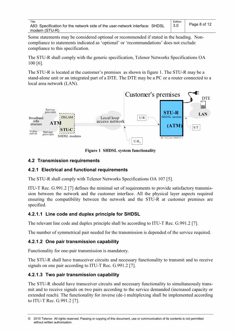
The STU-R is located at the customer’s premises as shown in figure 1. The STU-R may be a
stand-alone unit or an integrated part of a DTE. The DTE may be a PC or a router connected to a
local area network (LAN).
DSLAM
STU-C
SHDSL modems
Videoserver
Local loopaccess network
STU-R SHDSL modem
(ATM)
Pkl FoU-Lsm 20040121-1
ATM
LANBroadband
infrastructure
U-R
Serviceprovider
Serviceprovider
Customer's premises
S/T
U-R 0
DTE
Figure 1 SHDSL system functionality
4.2 Transmission requirements
4.2.1 Electrical and functional requirements
The STU-R shall comply with Telenor Networks Specifications OA 107 [5].
ITU-T Rec. G.991.2 [7] defines the minimal set of requirements to provide satisfactory transmis-
sion between the network and the customer interface. All the physical layer aspects required
ensuring the compatibility between the network and the STU-R at customer premises are
specified.
4.2.1.1 Line code and duplex principle for SHDSL
The relevant line code and duplex principle shall be according to ITU-T Rec. G.991.2 [7].
The number of symmetrical pair needed for the transmission is depended of the service required.
4.2.1.2 One pair transmission capability
Functionality for one-pair transmission is mandatory.
The STU-R shall have transceiver circuits and necessary functionality to transmit and to receive
signals on one pair according to ITU-T Rec. G.991.2 [7].
4.2.1.3 Two pair transmission capability
The STU-R should have transceiver circuits and necessary functionality to simultaneously trans-
mit and to receive signals on two pairs according to the service demanded (increased capacity or
extended reach). The functionality for inverse (de-) multiplexing shall be implemented according
to ITU-T Rec. G.991.2 [7].
Page 9
Title
A83: Specification for the network side of the user-network interface: SHDSL modem (STU-R)
Edition
3.0 Page 9 of 12
© 2010 Telenor. All rights reserved. Passing or copying of this document, use or communication of its contents is not permitted without written authorisation.
4.2.1.4 M-pair mode (M ≤ 8) transmission capability
The functionality of inverse (de-) multiplexing shall be implemented according to Alcatel
Interface specifications on the ASAM 7300 platform according to [1] and ISAM 7302 [2], which
is based on ITU-T Rec. G.991.2 [7].
4.2.1.5 Intermediate regenerator(s)
The STU-R shall be able to operate in presence of intermediate regenerator(s). The provision of
remote power feeding for the regenerator(s) is not a part of this specification.
4.2.1.6 ATM transport
The equipment shall transport ATM cells over SHDSL according to ITU-T Rec. G.991.2 [7]. For
cell transport, the ATM-specific parts shall apply.
4.2.2 Interworking with the STU-C of Telenor
The Telenor transport service ATM over SHDSL is presently supplied by two vendors of STU-C:
Alcatel and Nokia. The STU-R shall comply with both vendors, according to clauses 4.2.2.1,
4.2.2.2, 4.2.2.3 and 4.2.2.4.
4.2.2.1 Compatibility for Alcatel Lucent ASAM 7300 SHDSL line cards
The STU-R shall interwork with the STU-C depicted in Alcatel Interface specification ASAM
Release 4.2 for 7300 ASAM, ATM Subscriber Access Multiplexer [1] regarding ITU-T Rec.
G.991.2.
ITU-T Rec. G.991.2 Annex A is not applicable.
4.2.2.2 Compatibility for Alcatel Lucent ISAM 7302 SHDSL line cards
The STU-R shall interwork with the STU-C as defined in Alcatel Lucent 7302 ISAM compliance
with xDSL modems [2] regarding ITU-T Rec. G.991.2.
ITU-T Rec. G.991.2 Annex A is not applicable.
4.2.2.3 Compatibility for Nokia D50e SHDSL line cards
The STU-R shall interwork with the STU-C depicted in Nokia Interface specification D50e DSL
interface specification for Telenor Networks [3] regarding ITU-T Rec. G.991.2 (not applicable in
M-pair mode operation).
ITU-T Rec. G.991.2 Annex A is not applicable.
4.2.2.4 Compatibility for Nokia D500 SHDSL line cards
The STU-R shall interwork with the STU-C depicted in Nokia D500 DSLAM Public Interface
Specification, Interface Specification D500 R.3.1, R2.2 [4] regarding ITU-T Rec. G.991.2 (not
available in M-pair mode operation - under consideration).
ITU-T Rec. G.991.2 Annex A is not applicable.
Page 10
Title
A83: Specification for the network side of the user-network interface: SHDSL modem (STU-R)
Edition
3.0 Page 10 of 12
© 2010 Telenor. All rights reserved. Passing or copying of this document, use or communication of its contents is not permitted without written authorisation.
4.2.3 Performance
The reach requirements shall apply with STU-R connected to STU-C for all cases as specified in
section 4.2.2.1, 4.2.2.2, 4.2.2.3 and 4.2.2.4.
4.2.3.1 Reach for symmetrical bit rate, one pair transmission
The STU-R shall at least support symmetrical transmission on a distance L2 as defined in ITU-T
rec. G.991.2 /Table B-2 [7].
The tests shall be performed to confirm compliance to section 4.2.2.1, 4.2.2.2, 4.2.2.3 and
4.2.2.4.
4.2.3.2 Reach for symmetrical bit rate, M-pair transmission
The reach of the M-pair transmission shall be equal to the one pair transmission as specified in
section 4.2.3.1.
4.2.3.3 Sync time
The sync time shall be according to ITU-T rec. G.991.2 [7].
4.3 Management and configuration
4.3.1 Vendor identification notation (recommendations)
The STU-C should be able to identify the vendor of the remote STU-R. The data in the vendor
ID information block should be available as specified in ITU-T Rec. G.994.1 [8].
4.3.2 Dying gasp (recommendations)
The STU-R should be able to detect when the electrical power has been shut off (loss of power)
according to ITU-T Rec. G.991.2 [7].
4.4 ATM requirements
4.4.1 Functionality
The present ATM service categories supported by Telenor are UBR.1, UBR+, and nrt-VBR with
conformance VBR.3.
4.4.2 F5 loop back
The ATM OAM F5 end-to-end or segment loop-back functionality at virtual channel level
according to ITU-T Rec. I.610 [10] shall be supported.
4.4.3 Pre-configuration of VPI/VCI
A PVC shall be pre-configured with VPI/VCI = 8/35.
4.4.4 Performance functions
The bitrate measured on the ATM level, the ATM header included, should be close to the DSL
bitrate verified in section 4.2.3.1 and – if applicable – also in section 4.2.3.2.
Page 11
Title
A83: Specification for the network side of the user-network interface: SHDSL modem (STU-R)
Edition
3.0 Page 11 of 12
© 2010 Telenor. All rights reserved. Passing or copying of this document, use or communication of its contents is not permitted without written authorisation.
4.5 Auxiliary requirements
4.5.1 No pre-configuration needed
Before customer installation and start up, no configuration of the STU-R shall be necessary.
4.6 Physical interface and indicators
4.6.1 Customer premise’s interface, U-R0
The wall socket terminating the access network complies with EN 60603-7 [12] (RJ45).
Pair one is connected to pins 4 and 5. Optionally pair two is connected to pins 3 and 6, pair three
is connected to pins 1 and 2 and pair four is connected to pins 7 and 8.
In case of M-pair mode (M=5 to 8) operation, pairs 5 to 8 are terminated to a separate wall
socket. Pair five is then connected to pins 4 and 5, pair six is connected to pins 3 and 6, pair
seven is connected to pins 1 and 2 and pair eight is connected to pins 7 and 8.
It is important to notice that the provision of cabling arrangements to connect STU-R to the wall
socket is at the responsibility of the STU-R provider.
4.6.1.1 External adaptor for one pair connections only (optional)
In case the wall socket terminating the access network is the old three-pin Norwegian/Finish, an
adapter with socket according to EN 60603-7 [12] (RJ45) may be applied (as illustrated).
4.6.2 SHDSL port, U-R (recommendations)
To be decided by the vendor. In case connector is according to EN 60603-7 [12] (RJ45), the pin
configuration may be equal to interface U-R0.
4.6.3 Power status indication
The STU-R shall indicate presence of power.
4.6.4 Link status Indication
The STU-R shall indicate the following status:
- SHDSL link not available
- SHDSL link available
4.6.5 Link initialisation state indication (recommendations)
The STU-R should indicate presence of link initialisation state (training).
4.6.6 Traffic status indication (recommendations)
The STU-R should indicate presence of SHDSL link traffic.
4.7 Environmental requirements
4.7.1 CE-marking
Equipment shall comply with requirements specified in order to obtain the CE marking.
Page 12
Title
A83: Specification for the network side of the user-network interface: SHDSL modem (STU-R)
Edition
3.0 Page 12 of 12
© 2010 Telenor. All rights reserved. Passing or copying of this document, use or communication of its contents is not permitted without written authorisation.
4.7.2 EMC
The EU directives concerning EMC are in force and conformance to these EU directives is
mandatory. The EU directives are made legal also in Norway (1989/366/EØF, 1991/263/EØF,
1993/97/EØF, 1992/31/EØF, 1993/68/EØF, 1999/05/EØF).
For requirements in Norwegian regulations, see the relevant EEC directives:
http://ec.europa.eu/enterprise/policies/european-standards/documents/harmonised-standards-
legislation/list-references/rtte/index_en.htm
4.7.3 Resistibility
4.7.3.1 Gas discharge tubes
The provision of gas discharge tubes is not mandatory. If gas discharge tubes are provided, the
requirements in Telenor Networks Specification OA 100 [6] clause 6.3 shall apply.
4.7.3.2 Protection (recommendations)
The major power distribution system in Norway is the IT system, which is more susceptible for
electromagnetic disturbances. It is recommended that equipment connected to telecommunication
lines or power lines should resist lightning pulses of 10 kV (instead of 4/6 kV as stated in K.21
[18]).
4.7.4 Climatic and mechanical recommendations
The modems (STU-R) will typically be ordered in large quantities and distributed by one and one
unit by public transportation.
4.7.4.1 Storage (recommendations)
Requirements in EN 300019-1-1 class1.2 [15] apply for storage. Humidity is normally not
controlled.
4.7.4.2 Transportation (recommendations)
Requirements in EN 300019-1-2 class 2.3 [16] apply for public transportation.
4.7.4.3 Operational (recommendations)
Requirements in EN 300019-1-3 class 3.2 [17] apply for stationary use at weather-protected
locations. Equipment may be exposed to direct sunshine and humidity is normally not controlled.
It is recommended that the equipment may operate over the temperature range of +5ºC to +55ºC.
4.8 Electrical safety
Requirements in CENELEC EN 60950 [13] apply in general.
Requirements in Norwegian regulations [20]: http://www.lovdata.no/cgi-wift/ldles?doc=/sf/sf/sf-
20000620-0628.html