PUBLICLY AVAILABLE SPECIFICATION PAS 108:2007 Specification for the production of tyre bales for use in construction ICS codes: 83.160.99; 91.100.01 NO COPYING WITHOUT BSI PERMISSION EXCEPT AS PERMITTED BY COPYRIGHT LAW British Standards Institution 389 Chiswick High Road London W4 4AL United Kingdom http://www.bsi-global.com ISBN 978 0 580 50349 8 9 780580 503498 ISBN 978-0-580-50349-8
Transcript
PUBLICLY AVAILABLE SPECIFICATION
PAS 108:2007
Specification for theproduction of tyre balesfor use in construction
ICS codes: 83.160.99; 91.100.01
NO COPYING WITHOUT BSI PERMISSION EXCEPT AS PERMITTED BY COPYRIGHT LAW
British Standards Institution389 Chiswick High RoadLondon W4 4ALUnited Kingdom
14 .......................... 6 Handling and storage of the bales
15 .......................... 7 Transport, storage on site and placement of the bales
Annexes16 .......................... Annex A (normative) Factory production control19 .......................... Annex B (normative) The measurement of
tyre bale properties21 .......................... Annex C (informative) Engineering properties and
behaviours of tyre bales associated with their use in construction
35 .......................... Annex D (informative) Applications of tyre bales in construction
54 .......................... Annex E (informative) End of service life options
55 .......................... Bibliography
ContentsPage
This Publicly AvailableSpecification comes into effect on 23 April 2007
ForewordThis Publicly Available Specification (PAS) has been developed by The Waste &Resources Action Programme (WRAP)1) in collaboration with the British StandardsInstitution (BSI). It has been written by Jonathan Simm of HR Wallingford2) and Dr Mike Winter of TRL Limited3).
The overall aim of this PAS is to provide a specificationthat can be adopted by suppliers for producing tyrebales such that potential customers will be assured thatthey are procuring a construction material of consistentand verifiable quality. Thus the core of this documentaddresses the production, handling, storage, transportand placement of standardized tyre bales, thedimensions and properties of which are described inthis PAS. In addition, guidance is given on engineeringproperties and typical construction applications.
Acknowledgement is given to the followingorganizations that were involved in the developmentof this specification.
• John Barritt, WRAP (The Waste & Resources ActionProgramme)
• Dr Ken Collins, University of Southampton
• Paul Hallett, Department of Trade and Industry
• Dr John Harris, Scottish Environment ProtectionAgency (SEPA)
• Steven Mendes, Anglo Environmental
• Dennis Scott, Northern Tyre Recycling
• Peter Senior, Faber Maunsell
• Andrew Usborne, Environment Agency
• Steve Waite, WRAP
Wider comments from other interested parties wereinvited by BSI. The expert contributions made by theorganizations and individuals consulted in thedevelopment of this PAS are gratefully acknowledged.
This Publicly Available Specification has been preparedand published by BSI, which retains its ownership andcopyright. BSI reserves the right to withdraw or amendthis Publicly Available Specification on receipt ofauthoritative advice that it is appropriate to do so. This Publicly Available Specification will be reviewed at intervals not exceeding two years. If technologicaldevelopments in this field require that the content ofthis PAS be reviewed before two years have elapsedthis will be completed and any amendments arisingfrom the review will be published as an amendedPublicly Available Specification and publicized inUpdate Standards.
This Publicly Available Specification is not to beregarded as a British Standard. It will be withdrawnupon publication of its contents in, or as, a BritishStandard.
Compliance with this Publicly Available Specificationdoes not of itself confer immunity from legalobligations.
This Publicly Available Specification does not purportto include all the necessary provisions of a contract.Users are responsible for its correct application.
Whilst every care has been taken in developing andcompiling this publication, The British StandardsInstitution nor the authors and contributors accept any liability whatsoever for any loss or damage caused,arising directly or indirectly, in connection with relianceon its contents except that such liability which may notbe excluded in law.
While steps have been taken to ensure its accuracy,WRAP cannot accept responsibility or be held liable toany person for any loss or damage arising out of or inconnection with this information being accurate,incomplete of misleading. The listing or featuring of aparticular product or company does not constitute anendorsement by WRAP and WRAP cannot guaranteethe performance of individual products or materials.For more detail, please refer to WRAP’s Terms &Conditions on its web site: www.wrap.org.uk
1) The Waste & Resources Action Programme was created to promote sustainable waste management and to createstable and efficient markets for recycled materials andproducts. www.wrap.org.uk
2) HR Wallingford is an independent company specialising inconsultancy and research in civil engineering hydraulics andthe water environment. www.hrwallingford.co.uk
3) TRL Limited undertakes research and specialist consultancy,and provides advice across a broad spectrum of transport,infrastructure, environment, waste and resource concerns.www.trl.co.uk
Introduction
The disposal of used tyres in the UK is a significantproblem; every day over 100,000 worn tyres are takenoff cars vans and trucks accounting for a total ofaround 46 million tyres (460,000 tonnes) per year. Of this figure, about 27 million tyres (260,000 tonnes)are from cars, with truck and van tyres making up the remainder.
The compression of whole tyres into bales offers one of a number of ways of putting post-consumer tyres to good use, at the same time reducing the use ofprimary materials (typically aggregates).
Conversion of post-consumer tyres into tyre bales iscurrently a process which is managed under the WasteManagement Licensing Regulations 1994 (as amended)[2]. The process of baling is a regulated activity, butRegulators in England and Wales are not activelypursuing licensing applications for tyre baling. InScotland, subject to limits on the amounts involved, the baling of waste tyres is now an exempt activity.Separately, the transport of whole tyres and tyre balesrequires a Waste Transfer Note as specified by theEnvironmental Protection (Duty of Care) Regulations1991 (as amended).
The specific use of bales (once manufactured) inconstruction is generally accepted by the waste
regulators in the UK as a low risk activity. Regulators inEngland and Wales are not actively pursuing licensingapplications for use of bales in construction; futureamendments to regulations may introduce exemptionsto cover this use. In Scotland the use of tyre bales incertain specified works is now an exempt activity.Studies to date have indicated that leachates are wellwithin regulatory limits and fire risks are acceptablysmall. Tyre bales offer significant advantages inconstruction projects due to their high permeabilityand low bulk density, whilst still providing goodfrictional response and stiffness.
This specification is intended to assist manufacturers of bales of post-consumer tyres to produce a highquality, consistent and traceable product for use inconstruction by responsible and competentorganizations. It is also intended to assist balers indemonstrating that their product is of a high andconsistent quality via their Factory Production Controlprocesses (see Annex A).
This specification encompasses the following activitiesand aspects of tyre bale manufacture, storage and usein construction:
• Receipt, inspection and cleaning of tyres (see Clause 3);
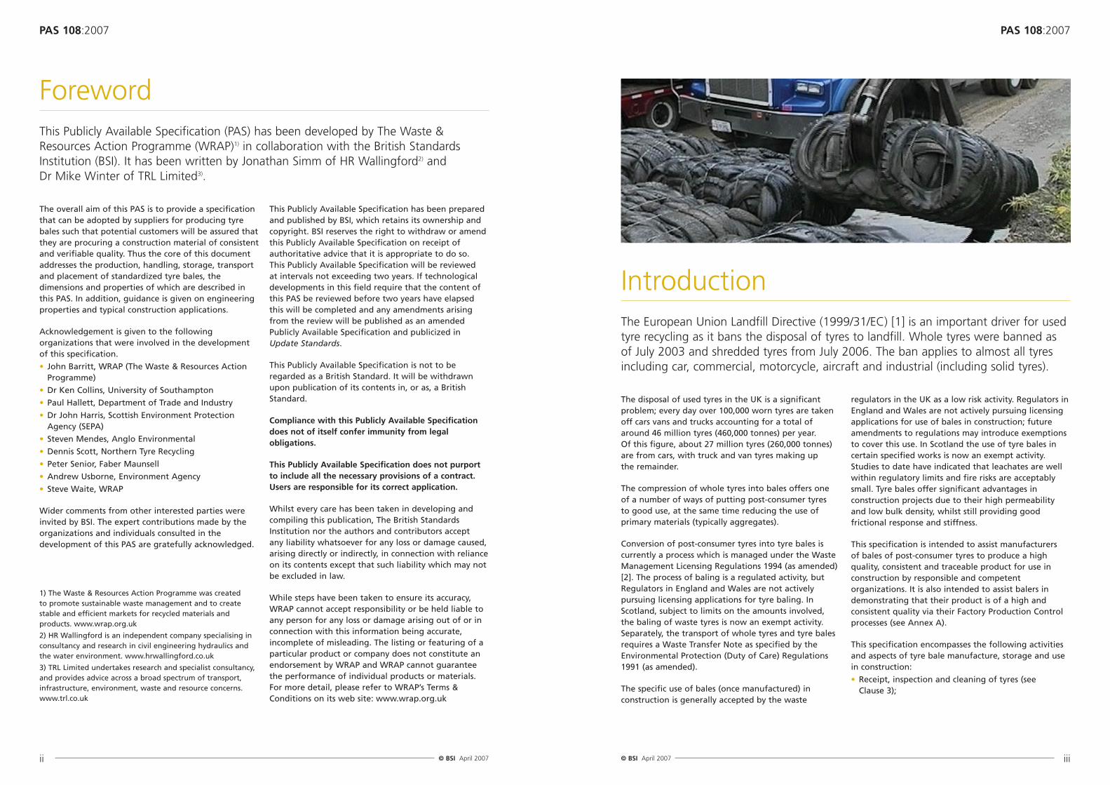
The European Union Landfill Directive (1999/31/EC) [1] is an important driver for usedtyre recycling as it bans the disposal of tyres to landfill. Whole tyres were banned asof July 2003 and shredded tyres from July 2006. The ban applies to almost all tyresincluding car, commercial, motorcycle, aircraft and industrial (including solid tyres).
This Publicly Available Specification specifies theminimum requirements for the manufacture of tyrebales for use in construction, including:
• the receipt, inspection, cleaning, handling andstorage of tyres intended for incorporation intobales;
• the process of compressing and baling, handling,transport, and storage of tyre bales intended for use in construction;
• the final placement of tyre bales into construction works;
• a factory production control procedure for tyre balemanufacture;
• the measurement of basic properties (dimensions,mass and density).
Information is also given on the likely engineeringproperties and behaviours of tyre bales, procedures for measuring the properties, potential applications for tyre bales for use in construction, and end ofservice life options.
NOTE Attention is drawn to the following regulations:
The Management of Health and Safety at Work Regulations1999 [3].
The Provision and Use of Work Equipment Regulations 1998 [4].
The Personal Protective Equipment Work Regulations 1992 [5].
The Construction (Design and Management) Regulations1994 [6].
2 Terms and definitions
For the purposes of this PAS, the following terms anddefinitions apply.
2.1 capping tyre non-low profile tyre from wheels with a rim diameterof 14 inches or greater
2.2 compressed bale lengthfinal dimension of the bale within the tyre balingmachine in the direction of application of thecompressive load prior to fixing of tie wires and releaseof compressive load
2.3 construction worksengineering works designed and executed with dueskill and care in a manner appropriate to the purposeof the structure and subject to relevant planning andenvironmental controls
• Handling and storage of tyres (see Clause 4);
• Production of reference bales and both larger and smaller sizes of bale, including a system formeasuring and labelling bales manufactured inaccordance with this PAS (see Clause 5);
• Handling and storage of the bales (see Clause 6);
• Transport, storage on site and placement of the bales (see Clause 7);
• Factory production control (see Annex A).
This specification is based on reference balesmanufactured in a standard width baling machine. The length of bales produced in such machines can be varied from the reference length. In addition thisspecification permits the production of two prescribedalternative widths of bales, but it is important to notethat baling machines to manufacture such modified-width bales may not be commercially available. Whilstthe use of reference width bales is encouraged,alternative width bales may be useful in certainspecialist applications.
This PAS has been prepared based on current UKpractice within the industry and covers the bale sizesspecified herein. However, in the future alternative and satisfactory rectilinear shapes of bales and/or formsof tying/wrapping of the bales may be developed toproduce bales that are useful for constructionpurposes. The properties of these bales can be testedusing the methods set out in Annex C. For acceptableuse in construction, the densities of the new bales (and hence their porosities and permeabilities) shouldbe similar to those indicated in Annex C, Table C1. Care will also be needed over the tyre placing patternadopted when placing the tyres in the baler to ensuresatisfactory structural properties for the bale. Evidenceof satisfactory performance derived from such testingwill help to make the case for revising this PAS toinclude new bale types.
Guidance is given to assist construction professionals in formulating preliminary design and constructionproposals. This guidance is not intended to cover allaspects of detailed design but to provide keyinformation that could not be sourced from otherengineering documents. This information includes:
• The measurement of relevant tyre bale properties(Annex B);
• Engineering properties and behaviours of tyre bales associated with their use in construction (see Annex C);
• Example applications for tyre bales in construction(see Annex D);
• End of service life disposal options for tyre bales (see Annex E).
2.4 depth of balethe smaller of the two principal dimensions (see Figure1) of the enclosing cuboid perpendicular to the lengthdimension as determined in accordance with this PAS
2.5 enclosing cuboidthe smallest cuboid (see Figure 1) which just fits arounda completed tyre bale
2.6 length of balethe finished dimension (see Figure 1) of the enclosingcuboid in the direction of application of thecompressive load in the tyre baling machine asdetermined in accordance with this PAS
NOTE 1 Dotted line in Figure 1 indicates enclosing cuboid.
NOTE 2 Configuration of tyres and tie wires in Figure 1 isbased on that in a reference bale (see 5.2)
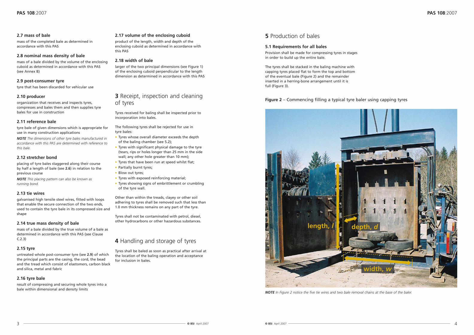
5.1 Requirements for all balesProvision shall be made for compressing tyres in stagesin order to build up the entire bale.
The tyres shall be stacked in the baling machine withcapping tyres placed flat to form the top and bottomof the eventual bale (Figure 2) and the remainderinserted in a herring-bone arrangement until it is full (Figure 3).
2.7 mass of balemass of the completed bale as determined inaccordance with this PAS
2.8 nominal mass density of balemass of a bale divided by the volume of the enclosingcuboid as determined in accordance with this PAS (see Annex B)
2.9 post-consumer tyretyre that has been discarded for vehicular use
2.10 producerorganization that receives and inspects tyres,compresses and bales them and then supplies tyrebales for use in construction
2.11 reference baletyre bale of given dimensions which is appropriate foruse in many construction applications
NOTE The dimensions of other tyre bales manufactured inaccordance with this PAS are determined with reference tothis bale.
2.12 stretcher bondplacing of tyre bales staggered along their course by half a length of bale (see 2.6) in relation to theprevious course
NOTE This placing pattern can also be known as running bond.
2.13 tie wiresgalvanised high tensile steel wires, fitted with loopsthat enable the secure connection of the two ends,used to contain the tyre bale in its compressed size andshape
2.14 true mass density of balemass of a bale divided by the true volume of a bale asdetermined in accordance with this PAS (see ClauseC.2.3)
2.15 tyreuntreated whole post-consumer tyre (see 2.9) of whichthe principal parts are the casing, the cord, the beadand the tread which consist of elastomers, carbon blackand silica, metal and fabric
2.16 tyre bale result of compressing and securing whole tyres into abale within dimensional and density limits
2.17 volume of the enclosing cuboidproduct of the length, width and depth of theenclosing cuboid as determined in accordance with this PAS
2.18 width of balelarger of the two principal dimensions (see Figure 1) of the enclosing cuboid perpendicular to the lengthdimension as determined in accordance with this PAS
3 Receipt, inspection and cleaning of tyres
Tyres received for baling shall be inspected prior toincorporation into bales.
The following tyres shall be rejected for use in tyre bales:
• Tyres whose overall diameter exceeds the depth of the baling chamber (see 5.2);
• Tyres with significant physical damage to the tyre(tears, rips or holes longer than 25 mm in the sidewall; any other hole greater than 10 mm);
• Tyres that have been run at speed whilst flat;
• Partially burnt tyres;
• Blow out tyres;
• Tyres with exposed reinforcing material;
• Tyres showing signs of embrittlement or crumbling of the tyre wall.
Other than within the treads, clayey or other soiladhering to tyres shall be removed such that less than1.0 mm thickness remains on any part of the tyre.
Tyres shall not be contaminated with petrol, diesel,other hydrocarbons or other hazardous substances.
4 Handling and storage of tyres
Tyres shall be baled as soon as practical after arrival atthe location of the baling operation and acceptancefor inclusion in bales.
5 Production of bales
Figure 2 – Commencing filling a typical tyre baler using capping tyres
NOTE In Figure 2 notice the five tie wires and two bale removal chains at the base of the baler.
Figure 3 – Filling a typical tyre baler withtyres in a herring-bone pattern
The tyres shall then be compressed in the direction ofthe application of the load.
This process shall be repeated until the requisitenumber of tyres has been incorporated and therequired compressed bale length has been achieved(see Figures 4 to 7).
The doors of balers shall not be opened duringcompression operations.
NOTE The door of the baler shown in Figure 4 was openedespecially for the purpose of illustrating this PAS.
Figure 5 – Further tyres added to the baleready for further compression. A typical tyrebaler is shown
Figure 6 – Filling a typical tyre baler, cappingtyres on the top
Figure 7 – A fully compressed bale with tie wires ready to wrap around a balemanufactured in a typical tyre baler
Figure 8 – Connecting the ends of the tiewires together (main picture) and afterconnection (inset)
Provision shall be made to wrap tie wires around thereference bale when it is under maximum compression(see Figure 7).
These shall comprise high tensile steel wires of aminimum diameter of 3.8 mm, (tensile strength 1,500 MPa to 1,700 MPa).
All wires supplied for use in bales shall be looped attheir ends and then electro-galvanised to a thickness of at least 3 μm or hot dip galvanised to a thickness of at least 6 μm.
The tie wires shall then be fitted to the bale (seeFigures 8 and 9) such that they are evenly spaced and approximately parallel around the perimeter of the bale.
Figure 10 – As the platen is raised the slack istaken up in the bale removal chains.
NOTE 1 Designers should be aware that the outputdimensions of all tyre bales will vary from the nominal valuesdepending on the tyres used and the depth will generally beslightly greater than the depth of the chamber. Typicaloutput bale dimensions are given in Annex C.
NOTE 2 The number of tyres contained in each balemanufactured in accordance with this specification is likelyto depend on the range and proportions of vehicle typesfrom which the tyres originated. Such variations may besignificant on a regional basis.
NOTE 3 The likely ranges of nominal mass density and truemass density of tyre bales, based on researchmeasurements, may be found in Table C.2 of Annex C.
Figure 11 – The chains tip the bale out of atypical baler
Figure 12 – The bale is removed from atypical baling machine
NOTE 4 Due to the degree of compression required (volumecompression ratios are typically 4 or 5 to 1), it is normallynecessary to compress the bale in more than one stage,securing the part compressed bale temporarily prior toadding additional tyres and completing the compressionprocess.
NOTE 5 The advantages of using capping tyres placed flatat the top and bottom of the bale include:
a) The tie wires are less likely to penetrate into the tyrematerial on the edges of the bales;
b) The resulting bale is of a more rectilinear form.
5.4 Reduced width bales5.4.1 Full length reduced width bale
Each full length reduced width bale shall contain atleast 66 tyres selected in accordance with Clause 3.
Each bale shall be formed in a baling machine with anequivalent rectilinear cavity measuring 2.0 m (± 0.1 m)in the direction of compression, 1.15 m (± 0.05 m) inwidth and 0.75 m (± 0.05 m) in depth.
The number of capping tyres to be placed flat adjacentto one another at the top and bottom of the bale inaccordance with 5.1 shall be two at the top and two atthe bottom of the bale.
Four tie wires shall be used each 3.5 m long includingloops.
The compressed bale length prior to fixing of tie wiresshall be 1.10 m.
5.4.2 Reduced length reduced width bale
Each reduced length bale shall be formed in a balingmachine with a rectilinear cavity measuring 1.15 m (± 0.05 m) in width and 0.75 m (± 0.05 m) in depth.
The number of capping tyres to be placed flat adjacentto one another at the top and bottom of the bale inaccordance with 5.1 shall be two at the top and two atthe bottom of the bale.
Each reduced length bale shall contain a number oftyres selected in accordance with Clause 3 andappropriate to the selected compressed bale lengthand achieving the density required by 5.1.
Four tie wires shall be used.
The length of each tie wire, including loops, shall be ofreduced length compared with the length of tie wiresused in the production of reference bales.
The reduced length shall be calculated using:
where
l is the length of a reduced length bale and
lref is the length of a reference bale.
NOTE 1 The values of both lref and l are dimensions for the length of a completed bale and not for the compressedlength of a bale immediately prior to placement of the tie wires.
NOTE 2 The length of tie wires can be estimated using 5.3including Note 1.
NOTE 3 The numbers of tyres required in the bale can bemade using the guidance given in the Note 2 to 5.3, butreplacing Nref by the number of tyres in a full lengthreduced width bale.
5.5 Increased width bale5.5.1 Full length increased width bale
Each full length increased width bale shall contain atleast 133 tyres selected in accordance with Clause 3.
Each bale shall be formed in a baling machine with anequivalent rectilinear cavity measuring 2.0 m (± 0.1 m)in the direction of compression, 1.95 m (± 0.05 m) inwidth and 0.75 m (± 0.05 m) in depth.
The number of capping tyres to be placed flat adjacentto one another at the top and bottom of the bale inaccordance with 5.1 shall be four at the top and fourat the bottom of the bale.
Six tie wires shall be used each 3.5 m long includingloops.
The compressed bale length prior to fixing of tie wiresshall be 1.10 m.
5.5.2 Reduced length increased width bale
Each reduced length bale shall be formed in a balingmachine with a rectilinear cavity measuring 1.95 m (± 0.05 m) in width and 0.75 m (± 0.05 m) in depth.
The number of capping tyres to be placed flat adjacentto one another at the top and bottom of the bale inaccordance with 5.1 shall be four at the top and fourat the bottom of the bale.
Each reduced length bale shall contain a number oftyres selected in accordance with Clause 3 andappropriate to the selected compressed bale lengthand achieving the density required by 5.1.
Six tie wires shall be used.
The length of each tie wire, including loops, shall be ofreduced length compared with the length of tie wiresused in the production of reference bales.
5.2 Reference balesEach reference bale shall contain at least 100 tyresselected in accordance with Clause 3.
Each reference bale shall be formed in a balingmachine with a rectilinear cavity measuring 2.0 m (± 0.1 m) in the direction of compression, 1.55 m (± 0.05 m) in width and 0.75 m (± 0.05 m) in depth.
The number of capping tyres to be placed flat adjacentto one another at the top and bottom of the bale inaccordance with 5.1 shall be three at the top and three at the bottom of the bale.
Five tie wires shall be used each 3.5 m long includingloops.
The compressed bale length prior to fixing of tie wiresshall be 1.10 m.
NOTE 1 The number of tyres within a reference bale willtypically vary between about 100 and 115 tyres.
NOTE 2 When compressing the bale, typical balingmachines are capable of applying forces of the order of 600 kN.
NOTE 3 Measurements on 50 bales produced to thisspecification using two machines gave the following output values:
• Length 1.33 m (+ 0.08 m/-0.06 m)
• Width 1.55 m (± 0.07 m)
• Depth 0.83 m (± 0.04 m)
A factor influencing the depth of the bales is the mix oftyres used.
NOTE 4 For some applications bales of sizes different fromthe reference bale may be more appropriate to the end usebut a consistent size of bale should be used for a particularproject or application.
5.3 Reduced length baleEach reduced length bale shall be formed in a balingmachine with a rectilinear cavity measuring 1.55 m (± 0.05 m) in width and 0.75 m (± 0.05 m) in depth.
The number of capping tyres to be placed flat adjacentto one another at the top and bottom of the bale inaccordance with 5.1 shall be three at the top and threeat the bottom of the bale.
Each reduced length bale shall contain a number oftyres selected in accordance with Clause 3 andappropriate to the selected compressed bale lengthand achieving the density required by 5.1.
Five tie wires shall be used.
The length of each tie wire, including loops, shall be ofreduced length compared with the length of tie wiresused in the production of reference bales.
N = (Nref l)lref
l = 3.5 – 2 (lref – l)
The reduced length shall be calculated using:
wherel is the length of a reduced length bale and
lref is the length of a reference bale.
NOTE 1 The values of both lref and l are dimensions for thelength of a completed bale and not for the compressedlength of a bale immediately prior to placement of the tie wires.
NOTE 2 If the length of the reduced-length bale, l, which itis desired to use in the reduced-length bale, is known, anestimate of the number of tyres, N, after the final stage ofcompression prior to fastening the tie wires may becalculated using:
where
Nref is the number of tyres in a reference bale, and
lref is the length of a reference bale.
Or, if the number of tyres, N, which it is desired to use inthe reduced-length bale, is known, an estimate of thelength of the reduced-length bale, l, after the final stage of compression prior to fastening the tie wires may becalculated using:
If information on the dimensions and number of tyres usedin the manufacture of reference bales with the mix of tyresto be employed in the reduced length bales is available then this should be used in the above equations. If suchinformation is not available then information presented in this specification may be used as a starting point fordetermining either the length of bale that will be requiredwhen a specific number of tyres is used or the number oftyres required to produce a tyre bale of a specific length.Adjustments to the number of tyres (or the length of thebale) can then be made until the required density of bale is achieved.
6 Handling and storage of the balesat the baling facility
Bales shall always be lifted in a manner which avoidsdamage to the tie wires of the completed bale.
Tyre bales shall never be lifted by the tie wires.
The stacking of tyre bales shall be arranged so as toensure stability of the stack.
Subsequent layers of bales shall be stacked in astretcher bond pattern.
Bales shall be organized in such a way as to permitproper rotation of stock.
Bales shall be stored at approved storage locations andsubject always to any statutory or licensing restrictions.
If bales need to be stored for more than 12 months,then the producer shall demonstrate the need for theadditional storage time on the basis of evidence oforders received and the additional storage time shallbe agreed, as necessary, with the regulatoryauthorities.
NOTE 1 Wood bolsters under the first layer of bales may be used to lay back the front face of bale stacks as an aid to stability.
NOTE 2 A ‘loggers’-clam’, brick grab or forklift should beused for lifting and handling tyre bales during storage.
NOTE 3 The stacking of tyre bales should be organized in such a way as to minimize their exposure of tyres tosunlight and thus the potential further degradation due to UV-exposure.
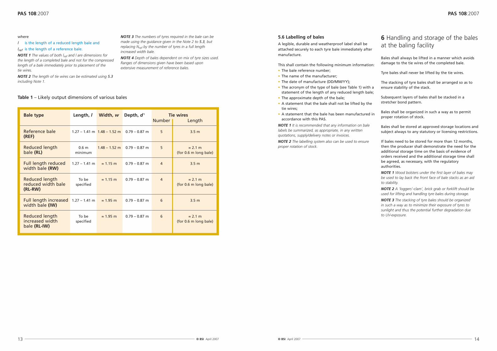
Table 1 – Likely output dimensions of various bales
5.6 Labelling of balesA legible, durable and weatherproof label shall beattached securely to each tyre bale immediately aftermanufacture.
This shall contain the following minimum information:
• The bale reference number;
• The name of the manufacturer;
• The date of manufacture (DD/MM/YY);
• The acronym of the type of bale (see Table 1) with astatement of the length of any reduced length bale;
• The approximate depth of the bale;
• A statement that the bale shall not be lifted by thetie wires;
• A statement that the bale has been manufactured inaccordance with this PAS.
NOTE 1 It is recommended that any information on balelabels be summarized, as appropriate, in any writtenquotations, supply/delivery notes or invoices.
NOTE 2 The labelling system also can be used to ensureproper rotation of stock.
Bale type Length, l Width, w Depth, d 1 Tie wires Number Length
Reference bale 1.27 – 1.41 m 1.48 – 1.52 m 0.79 – 0.87 m 5 3.5 m(REF)
Reduced length 0.6 m 1.48 – 1.52 m 0.79 – 0.87 m 5 ≈ 2.1 mbale (RL) minimum (for 0.6 m long bale)
Full length reduced 1.27 – 1.41 m ≈ 1.15 m 0.79 – 0.87 m 4 3.5 mwidth bale (RW)
Reduced length To be ≈ 1.15 m 0.79 – 0.87 m 4 ≈ 2.1 mreduced width bale specified (for 0.6 m long bale)(RL-RW)
Full length increased 1.27 – 1.41 m ≈ 1.95 m 0.79 – 0.87 m 6 3.5 mwidth bale (IW)
Reduced length To be ≈ 1.95 m 0.79 – 0.87 m 6 ≈ 2.1 mincreased width specified (for 0.6 m long bale)bale (RL-IW)
where
l is the length of a reduced length bale and
lref is the length of a reference bale.
NOTE 1 The values of both lref and l are dimensions for the length of a completed bale and not for the compressedlength of a bale immediately prior to placement of the tie wires.
NOTE 2 The length of tie wires can be estimated using 5.3including Note 1.
NOTE 3 The numbers of tyres required in the bale can bemade using the guidance given in the Note 2 to 5.3, butreplacing Nref by the number of tyres in a full lengthincreased width bale.
NOTE 4 Depth of bales dependent on mix of tyre sizes used.Ranges of dimensions given have been based uponextensive measurement of reference bales.
NOTE 1 Wood bolsters under the first layer of bales may beused to help lay back the front face of bale stacks as an aidto stability.
NOTE 2 Experience has shown that a ‘loggers’-clam’ (Figure 14), brick grab or forklift are effective tools for liftingand handling tyre bales during storage on site. However,when placing bales in their final position in constructionworks, it is useful to be able to rotate and positively placethe bales and, for this purpose, experience shows that a‘loggers’-clam’ or brick grab are the most effective tools.
NOTE 3 Best confinement of bales will normally be achievedby placing the bales such that the tie wires are parallel tothe longer axis of the structure. For example, in the case of
a linear structure, such as a road or an embankment, thebales should be placed such that the tie wires are in linewith the direction of the chainage. Tight abutting of the bales ensures that the friction between the bales is maximized.
NOTE 4 As well as a longitudinal stretcher bond, the formof construction may or may not require a stagger in thebales and/or the joints between the bales in the transversedirection. Examples of both staggered and non-staggeredjoints between bales in transverse courses are illustrated inAnnex D.
NOTE 5 Details of uses of bales in construction, includingsome structure-specific suggestions, are given in Annex D.
A.1 IntroductionThis Annex specifies a factory production controlsystem for tyre bales to ensure that they conform tothe requirements of this standard.
The performance of the factory production controlsystem shall be assessed according to the principlesused in this Annex.
A.2 OrganizationA.2.1 Responsibility and authority
The responsibility, authority and the interrelationbetween all personnel who manage, perform andcheck work affecting quality shall be defined, includingpersonnel who need organizational freedom andauthority to:
a) initiate action to prevent the occurrence of productnon-conformity;
b) identify, record and deal with any product qualitydeviations.
A.2.2 Management representative for factory production control
For every plant producing tyre bales the producer shallappoint a person with appropriate authority to ensurethat the requirements given in this Annex areimplemented and maintained.
A.2.3 Management review
The factory production control system adopted tosatisfy the requirements of this Annex shall be auditedand reviewed at appropriate intervals by managementto ensure its continuing suitability and effectiveness.
Records of such reviews shall be maintained.
A.3 Control proceduresA.3.1 General
The producer shall establish and maintain a factoryproduction control manual setting out the proceduresby which the requirements for factory productioncontrol are satisfied.
A.3.2 Document and data control
A procedure concerning the management ofdocuments and data shall be documented in theproduction control manual covering procedures andresponsibilities for approval, issue, distribution andadministration of internal and external documentation
and data; and the preparation, issue and recording ofchanges to documentation.
A.3.3 Sub-contract services
If any part of the operation is sub-contracted by theproducer a means of control shall be established.
A.4 Management of the productionThe factory production control system shall fulfil thefollowing requirements:
a) There shall be procedures to identify and control the materials;
b) There shall be procedures to ensure that bales areput into stock in a controlled manner and thestorage locations are identified by bale referencenumber and date;
c) There shall be procedures to ensure that bales taken from stock have not deteriorated in such away that their conformity is compromised;
d) Each bale shall be identifiable up to the point of use.
A.5 Inspection and testA.5.1 General
The producer shall make available all the necessaryfacilities, equipment and trained personnel to carry outthe required inspections and tests.
A.5.2 Equipment
The producer shall be responsible for the control,calibration and maintenance of inspection, measuringand test equipment.
Equipment shall be used in accordance withdocumented procedures.
Equipment shall be uniquely identified.
Calibration records shall be retained.
A.5.3 Frequency and location of inspection, samplingand tests
The production control document shall describe thefrequency and nature of inspections. The frequency ofsampling and the tests when required shall be carriedout as specified in Table A.1.
NOTE 1 The requirements for factory production controlinclude visual inspection.
A.6 RecordsThe results of factory production control shall berecorded including sampling locations, dates and timesand product tested with any relevant information e.g. weather conditions.
Where the product inspected or tested does not satisfythe requirement laid down in the specification, or ifthere is an indication that it may not do so, a noteshall be made in the records of the steps taken to dealwith the situation (e.g. carrying out of a new testand/or measures to correct the production process).
The records required by all the clauses of this Annexshall be included.
The records shall be kept for at least the statutoryperiod.
NOTE “Statutory period” is the period of time records arerequired to be kept in accordance with Regulations applyingat the place of production.
A.7 Control of non-conforming productFollowing an inspection or test which indicates that a product does not conform the affected material shall be:
a) reprocessed; or
b diverted to another application for which it issuitable; or
c) rejected and marked as non-conforming.
All cases of non-conformity shall be recorded by theproducer, investigated and if necessary correctiveaction shall be taken.
NOTE Corrective actions could include:
a) investigation of the cause of non-conformity including an examination of the testing procedure and making any necessary adjustments;
b) analysis of processes, operations, quality records, servicereports and customer complaints to detect and eliminatepotential causes of non-conformity;
c) initiating preventive actions to deal with problems to a level corresponding to the risks encountered;
d) applying controls to ensure that effective correctiveactions are taken;
e) implementing and recording changes in proceduresresulting from corrective action.
A.8 Handling and storage in production areasThe producer shall make the necessary arrangementsto maintain the quality of the product during handlingand storage.
A.9 TransportThe producer’s factory production control system shallidentify the extent of his responsibility in relation totransport, delivery and storage on site.
A.10 Training of personnelA.10.1 General
The producer shall establish and maintain proceduresfor the training of all personnel involved in the factoryproduction system.
Records of training shall be maintained.
Operators shall receive practical training in themanufacture of tyre bales under the direct supervisionof competent persons before being allowed tomanufacture tyre bales for use in construction.
A.10.2 Competent person
A competent person is one who can demonstrate that they have sufficient professional knowledge ortechnical training, ability, actual experience andauthority to enable them to:
a) carry out their assigned duties at the level ofresponsibility allocated to them;
b) understand any potential hazards to the work (or equipment) under consideration;
c) detect any technical defects or omissions in thatwork (or equipment), recognize any implications forhealth and safety, where appropriate, caused bythose defects or omissions, and be able to specify a remedial action to mitigate those implications.
NOTE The level of responsibility within an organization will dictate the degree of competence required, e.g. morewill be expected of managers/supervisors than a shop floor worker.
NOTE 2 Any deviations indicated by these inspections maylead to increased test frequencies.
NOTE 3 When the measured value is close to a specifiedlimit the frequency may need to be increased.
NOTE 4 Under special conditions the test frequencies may be decreased below those given in Table A.1.Theseconditions could be:
a) Highly automated production equipment.
b) Long-term experience with constancy of specialproperties.
c) Sources of high conformity.
d) Running a Quality Management System with exceptionalmeasures for surveillance and monitoring of theproduction process.
The producer shall prepare a schedule of testfrequencies taking into account the minimumrequirements of Table A.1. All of the measurementsdescribed in Table A.1 shall be carried out on all balessampled.
Reasons for decreasing the test frequencies shall bestated in the factory production control document.
Table A.1 – Minimum test frequencies for general properties
Property Clause Notes/references Test method Minimum test frequency
1 Length, width and B.3.1 Dimensions of PAS 108 Annex B 10 bales per 1000depth of bale enclosing cuboid bales produced
2 Mass of bale B.3.2 Mass of tyres and tie wires PAS 108 Annex B 10 bales per 1000 comprising the bale bales produced
3 Volume of bale B.4.1 Volume of enclosing cuboid PAS 108 Annex B 10 bales per 1000bales produced
4 Mass density B.4.2 Mass density related to PAS 108 Annex B 10 bales per 1000of bale volume of enclosing cuboid bales produced
Annex B (normative)The measurement of tyre bale properties
B.1 PrincipleThe nominal mass density (mass density of theenclosing cuboid) of individual tyre bales shall bedetermined at the frequency prescribed in Annex A.
The principal dimensions of the enclosing cuboid (see Figure 1 in the main text of the PAS): length (l),width (w) and depth (d) shall be determined usingstraight laths and a tape measure. The mass shall bedetermined and the mass density computed by dividingthe mass by the volume of the enclosed cuboid.
B.2 ApparatusB.2.1 Two straight laths, of length greater than thelargest dimension of a tyre bale (l = 1.55 m for areference bale) to be tested.
B.2.2 Tape measure, readable to ± 25 mm of the largestdimension of the tyre bale to be measured.
B.2.3 Calliper as shown in Figure B.1.
B.2.4 Weighing equipment, accurate to ± 2 % of the mass to be measured (nominally ± 15 kg for areference bale).
ρ is the nominal mass density of the tyre bale in kg/m3.
V is the volume of the enclosing cuboid containing thetyre bale in m3.
The dimensions shall be recorded to the nearest 0.01 m, the mass to the nearest 10 kg, and the densityto the nearest 10 kg/m3.
B.5 Test ReportB.5.1 Required data
The test report shall include the following information:
• A statement that the bales have been manufacturedand tested in accordance with this PAS;
• Identity and address of the tyre bale manufacturer;
• Identity of the body carrying out the testing;
The test report shall also include the following data:
• The bale reference number;
• The date of manufacture;
• The type of bale (e.g. reference bale, reduced-lengthbale, reduced width bale);
• The dimensions, volume and mass density asdescribed in B.4;
• The date of test.
Figure B.1 – Calliper
Tape measure
L-SteelDimension
B.3.1 Dimensions
Position the bale such that its two extremities arebetween two straight laths positioned parallel to eachother, at right angles to the dimension to be measuredand coincident with the centreline of the face of thebale being measured. Measure each of the threeprinciple dimensions (l, w and d) at right angles to the laths using the tape measure to ± 25 mm.
If this accuracy cannot be met using the aboveprocedure the calliper (Figure B.1) shall be used.
B.3.2 Mass
The mass of each bale for which the dimensions aremeasured shall be measured using the weighingequipment.
If the bale needs to be moved or turned duringweighing this shall be achieved using suitable liftingplant. The bale shall not be moved by means ofmanual handling or by the tie wires.
B.4 Calculation and Expression of ResultsB.4.1 Volume
For each tyre bale the volume of the bale shall becalculated from the following equation:
where
l is the length of the tyre bale in metres;
w is the width of the tyre bale in metres;
d is the depth of the tyre bale in metres;
V is the volume of the tyre bale in m3.
B.4.2 Nominal Mass Density
For each tyre bale the nominal mass density shall becalculated from the following equation:
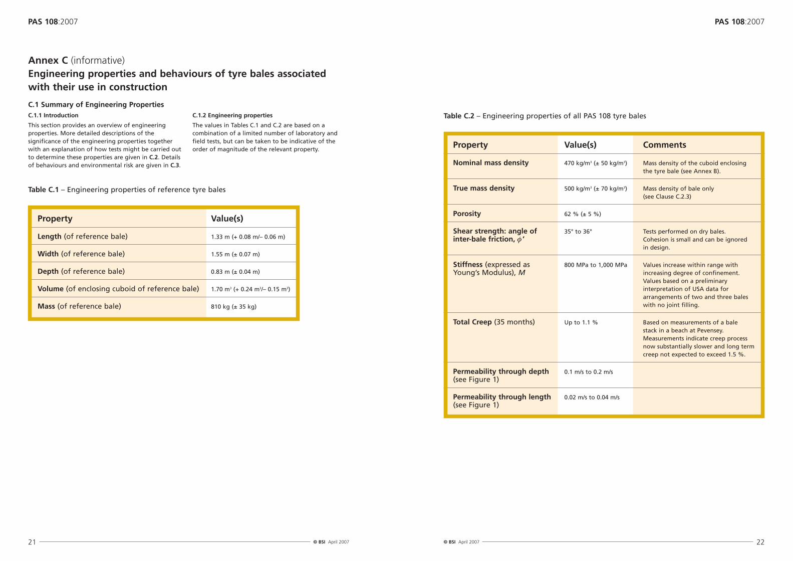
This section provides an overview of engineeringproperties. More detailed descriptions of thesignificance of the engineering properties togetherwith an explanation of how tests might be carried outto determine these properties are given in C.2. Detailsof behaviours and environmental risk are given in C.3.
C.1.2 Engineering properties
The values in Tables C.1 and C.2 are based on acombination of a limited number of laboratory andfield tests, but can be taken to be indicative of theorder of magnitude of the relevant property.
Annex C (informative)Engineering properties and behaviours of tyre bales associatedwith their use in construction
Table C.1 – Engineering properties of reference tyre bales
Property Value(s)
Length (of reference bale) 1.33 m (+ 0.08 m/– 0.06 m)
Table C.2 – Engineering properties of all PAS 108 tyre bales
Property Value(s) Comments
Nominal mass density 470 kg/m3 (± 50 kg/m3) Mass density of the cuboid enclosing the tyre bale (see Annex B).
True mass density 500 kg/m3 (± 70 kg/m3) Mass density of bale only (see Clause C.2.3)
Porosity 62 % (± 5 %)
Shear strength: angle of 35° to 36° Tests performed on dry bales.inter-bale friction, φ ’ Cohesion is small and can be ignored
in design.
Stiffness (expressed as 800 MPa to 1,000 MPa Values increase within range withYoung’s Modulus), M increasing degree of confinement.
Values based on a preliminaryinterpretation of USA data forarrangements of two and three bales with no joint filling.
Total Creep (35 months) Up to 1.1 % Based on measurements of a bale stack in a beach at Pevensey.Measurements indicate creep process now substantially slower and long termcreep not expected to exceed 1.5 %.
Permeability through depth 0.1 m/s to 0.2 m/s(see Figure 1)
Permeability through length 0.02 m/s to 0.04 m/s(see Figure 1)
Lift the tyre bale into tank of water using the liftingdevice with load cell or dynamometer. Still holding thetyre bale with the lifting device, add further steelingots until the bale is just submerged, but the trayand weights remain exposed to air. Record the weightof the submerged bale plus tray and ingots.
Lift the bale from the tank and remove the tray ofsteel weights and plastic wrapping.
Lower the bale back into the tank of water until it isjust fully immersed but still held by the lifting device.Note the weight at regular time intervals untilmeasurable changes have ceased. Record the stableweight of the submerged unwrapped tyre bale.
NOTE A variety of methods may be used to seal the tyrebale in flexible plastic wrapping. These include the use ofmachines designed to wrap agricultural products, and heator vacuum sealed plastic wrappers.
In this clause more detailed descriptions are given of the significance of the engineering propertiessummarized in the previous clause, together with an explanation of how tests might be carried out todetermine these properties. Each property is dealt with in turn, first explaining its significance and thendescribing how tests could be carried out to determinethat property.
In the event that a manufacturer wishes to promotethe widespread use of bales other than reference bales such testing will be of benefit in confirming any variations in their properties. Similarly if amanufacturer wishes to promote a type of baledifferent to the bale types/sizes described in the PAS (manufacturing process, shape, density, etc) theannex will give guidance on obtaining relevant datafor engineering design.
C.2.2 Dimensions, volume, mass, density and porosity
Apart from the practical need to know basicdimensional and mass properties when designing andbuilding structures, density and porosity are alsoimportant when assessing the stability of structures forexample against sliding and overturning and thevolumetric ability of a tyre stack to store water.
The measurement of enclosing cuboid dimensions andtyre bale mass and the calculation of enclosing cuboidvolume and density are described in Annex B. Once themass density of the enclosing cuboid, ρc , is known, it ispossible to infer the porosity, P, of this cuboid by usingthe known density of tyre material, ρTy:
This porosity can be used for assessing the volume ofwater that can be stored within a bale stack withoutgranular fill. (For the purposes of this calculation, ρTy can be taken as 1,300 ± 40 kg/m3.)
Should fill be included within the tyre bale stack thenit is also important to know the difference betweenthe volume of the tyre bale itself and its enclosingcuboid (estimated as being between 4 % and 8 % forreference bales). This is important both for estimatingthe amount of fill required and the resultant overallmass density and porosity of the resultant bale/fill mix(see Box D.1). A method for measuring these propertieswhen determining the porosity of the bales is given in C.2.3.
C.2.3 True volume, porosity and density of bale massand density of tyre material
C.2.3.1 Principle
The challenge when measuring the true volume andhence porosity and density of a tyre bale is its unevenexternal shape. The method therefore makes use ofArchimedes’ principle, namely that when a body iswholly or partially immersed in a fluid it experiences an upthrust force equal to the mass of liquid displaced.To exclude water from the bales, it is necessary to wrap the bales using flexible plastic wrapping beforesubmerging the bale and measuring its submergedweight.
Subsequently the wrapping is removed and the volumeof voids in the bale is determined with the assistanceof a further weighing of the unsealed bale in water.
NOTE A small amount of air will remain trapped in the voidsof the bale. Thus, the porosity determined by this test islikely to be a slight underestimate of the true value.However, the difference in porosity is not considered to besignificant for most engineering purposes.
C.2.3.2 Apparatus
C.2.3.2.1 Flexible plastic wrapping and means to makethis watertight.
C.2.3.2.2 Lifting equipment, including appropriatestraps/shackles, able to lift bale in and out of waterwithout using the tie wires.
C.2.3.2.3 Weighing device (dynamometer, load cell, etc)connected to lifting equipment able to weigh bales toan accuracy of ± 0.5%.
C.2.3.2.4 Tray of steel ingots of total mass at leastequivalent to that of the bale, each individual ingotweighing a known mass (e.g. 10 kg).
C.2.3.2.5 Tank of fresh water of sufficient dimensionsto hold tyre bale and water displaced by it.
C.2.3.3. Procedure
Weigh the tyre bale in air.
Seal the tyre bale in plastic wrapping and weigh baleagain in air.
Fill the tray with ingots to a total weight (including thetray) just smaller than that of the wrapped tyre bale.
Place the tray of steel ingots on top of the tyre baleand measure combined weight of the tyre bale and thetray of ingots.
MWDW = MTF = (MTBW + MTI ) + MAI – MTBW
VTB = MWDW / ρW
ρTB = MTB / VTB
P = (1000 – ρc ) / ρTy
C.2.3.4 Calculation and expression of results
Calculate mass of water displaced by wrapped tyre bale, MWDW, as equivalent to final mass of tray plus ingots,MTF required to submerge wrapped tyre bale as follows:
where
MTBW is the measured mass of wrapped tyre bale
MTI is the measured mass of initial tray of ingots
MAI is the measured mass of additional ingots required to finally submerge bale.
Calculate volume of tyre bale, VTB , as equivalent to the volume of water displaced by the wrapped tyre bale from:
where
ρW is the density of water in tank (assume 1,000 kg/m3 for fresh water at 20 °C).
Darcy’s law is used to determine the permeability oftyre bales. In its simplest form for steady flow througha media, it may be written as:
where
Q is the discharge (m3/s),
k is the permeability coefficient (m/s),
A is the flow cross sectional area (m2),
Δh is the head difference over flow length (m), and
L is the length of flow path (m).
C.2.4.3 Apparatus
C.2.4.3.1 A hydraulic recirculating discharge flume ofwidth greater than the width of the tyre bale beingtested (say not less than 2 m). The flume shall be ableto sustain a water depth of about 0.7 m and ameasurable steady state water flow discharge of notless than 0.10 m3/s. The flume shall have a means ofcontrolling the downstream water level to allow slowfilling of the flume and tyre bale at the start of a test(see C.2.4.4). This is best achieved by a tail gate thatcan be adjusted to produce free or controlled flow. If free outflow conditions are required, a false floormay need to be installed on which the tyre bale will sit.The flow discharge shall be measured using a flowmetering device of high accuracy (typically ± 2 %) suchas an electromagnetic flow meter or a calibratedmeasuring weir.
C.2.4.3.2 Accurately levelled, mounted point gauges orother devices for measurement of water depths in theflume to a repeatable accuracy of ± 1.0 mm.
C.2.4.3.3 Impermeable flume inserts of dimensions ableto make up the difference between the width of thebale and the width of the flume.
C.2.4.3.4 Foaming or other waterproof sealant to filluneven gaps between the sides of the bale and theflume inserts (see Figure C.1)
Q = k.A (Δh / L)
Figure C.1 – Bale in flume for permeability testing showing (timber) flume inserts andfoaming sealant between bale and flume/insert walls
C.2.4.4 Procedure
Measure (using the method of Annex B) and report alldimensions of the tyre bale. Record the orientation ofthe bale in the flume, including the bale dimension inthe direction in which flow is to take place and theheight of the bale from the (false) floor of the flume.
Install flume inserts.
Install bale in flume and secure on downstream side(e.g. with stanchions and bolts).
Figure C.2 – Flume set up for bale permeability testing
Direction of flow
Tail gate
h1 h2
L
Calculate the mass of water displaced by unwrappedtyre bale, MWD , from:
where
MTBS is the measured mass of submerged unwrappedtyre bale.F
Calculate volume of solid tyre material in bale, VTM ,equivalent to the volume of water displaced from:
where
ρW is the density of water in tank (1,000 kg/m3 forfresh water).
Calculate the porosity of the tyre bale from
Calculate the average density of the tyre bale material, ρTM, from:
where
MTB is the mass of the unwrapped tyre bale.
C.2.4 Permeability
C.2.4.1 Significance of engineering property
Permeability is a key parameter when bales are beingused with a drainage function, as it determines therate at which water is able to pass through and escapefrom the layer. It is also significant in regard to stabilityunder hydraulic loading as it will determine the way inwhich pore water pressures within the bale mass areable to dissipate. For example, reference bales do notfloat in steady state conditions, because they areporous and the density of tyre material is greater thanthat of water. However, under wave action, the balesappear to ‘float’ because their permeability is too lowfor the water to enter a significant proportion of thepore space.
Using foaming waterproof sealant, seal between baleand sides in contact with flume or insert wall. Also sealbottom edge in contact with floor of flume.
Making use of the tail gate (or other device) fill thedownstream end of the flume to allow gradual fillingthrough the tyre bale.
Slowly increase flow though flume increasing theupstream water depth until it appears to be constant,but without overtopping the tyre bale (Figure C.2).
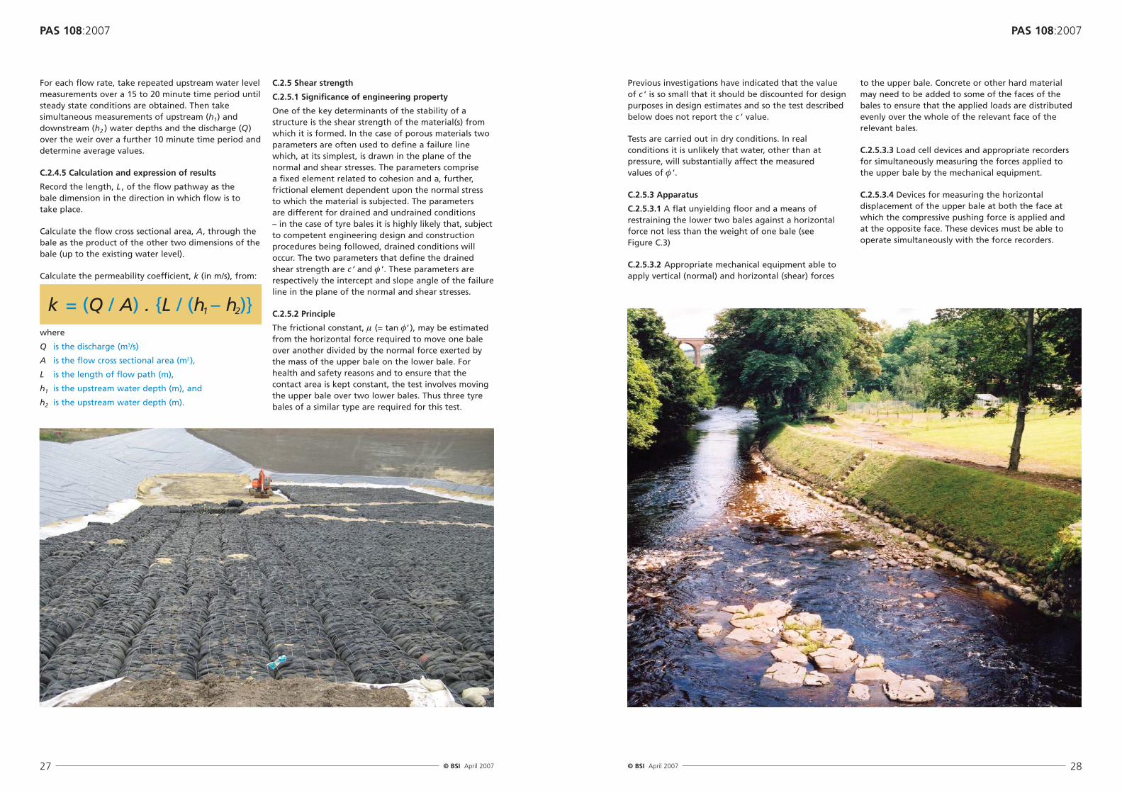
For each flow rate, take repeated upstream water levelmeasurements over a 15 to 20 minute time period untilsteady state conditions are obtained. Then takesimultaneous measurements of upstream (h1) anddownstream (h2 ) water depths and the discharge (Q)over the weir over a further 10 minute time period anddetermine average values.
C.2.4.5 Calculation and expression of results
Record the length, L , of the flow pathway as the bale dimension in the direction in which flow is to take place.
Calculate the flow cross sectional area, A, through thebale as the product of the other two dimensions of thebale (up to the existing water level).
Calculate the permeability coefficient, k (in m/s), from:
where
Q is the discharge (m3/s)
A is the flow cross sectional area (m2),
L is the length of flow path (m),
h1 is the upstream water depth (m), and
h2 is the upstream water depth (m).
C.2.5 Shear strength
C.2.5.1 Significance of engineering property
One of the key determinants of the stability of astructure is the shear strength of the material(s) fromwhich it is formed. In the case of porous materials twoparameters are often used to define a failure linewhich, at its simplest, is drawn in the plane of thenormal and shear stresses. The parameters comprise a fixed element related to cohesion and a, further,frictional element dependent upon the normal stress to which the material is subjected. The parameters are different for drained and undrained conditions – in the case of tyre bales it is highly likely that, subjectto competent engineering design and constructionprocedures being followed, drained conditions willoccur. The two parameters that define the drainedshear strength are c ’ and φ ’. These parameters arerespectively the intercept and slope angle of the failureline in the plane of the normal and shear stresses.
C.2.5.2 Principle
The frictional constant, μ (= tan φ’ ), may be estimatedfrom the horizontal force required to move one baleover another divided by the normal force exerted bythe mass of the upper bale on the lower bale. Forhealth and safety reasons and to ensure that thecontact area is kept constant, the test involves movingthe upper bale over two lower bales. Thus three tyrebales of a similar type are required for this test.
Previous investigations have indicated that the value of c ’ is so small that it should be discounted for designpurposes in design estimates and so the test describedbelow does not report the c ’ value.
Tests are carried out in dry conditions. In realconditions it is unlikely that water, other than atpressure, will substantially affect the measured values of φ ’.
C.2.5.3 Apparatus
C.2.5.3.1 A flat unyielding floor and a means ofrestraining the lower two bales against a horizontalforce not less than the weight of one bale (see Figure C.3)
C.2.5.3.2 Appropriate mechanical equipment able toapply vertical (normal) and horizontal (shear) forces
to the upper bale. Concrete or other hard material may need to be added to some of the faces of thebales to ensure that the applied loads are distributedevenly over the whole of the relevant face of therelevant bales.
C.2.5.3.3 Load cell devices and appropriate recordersfor simultaneously measuring the forces applied to the upper bale by the mechanical equipment.
C.2.5.3.4 Devices for measuring the horizontaldisplacement of the upper bale at both the face atwhich the compressive pushing force is applied and at the opposite face. These devices must be able tooperate simultaneously with the force recorders.
The stiffness or stress-strain response of the tyre bales is important because it determines the way thestructures, of which the bales form part, deform underloading, including both self weight and live loads. As such it is normally most important when assessingserviceability limit state conditions.
C.2.6.2 Principle
The stiffness of tyre bales, E (MN/m2), describes theextent to which the bales resist compression underload and is effectively the gradient of thestress/deformation curve.
Stiffness tests should ideally be in confined conditionsrepresenting those existing in most construction works.However, full confinement is difficult to achieve in thelaboratory, and simple unconfined tests are clearlymuch more straightforward, and will (conservatively)underestimate the stiffness. An analysis of work carriedout in the USA suggests that the underestimate is onlyof the order of 5 % to 15 % and should not be criticalfor most engineering applications.
The number of bales to be stacked and compressed isclearly a balance between maximising deflection inorder to minimise errors in measuring the compressivestrain and minimising the effects of lack ofconfinement. Experience suggests that two balesstacked vertically is the best compromise.
C.2.6.3 Apparatus
C.2.6.3.1 A flat unyielding floor.
C.2.6.3.2 Appropriate mechanical equipment able toapply vertical (normal) forces to the upper bale up to amaximum of between 50 kN and 100 kN. Concrete orother hard material may need to be added to some ofthe faces of the bales to ensure that the applied loadsare distributed evenly over the whole of the relevantface of the relevant bale.
C.2.6.3.3 Load cell device and deflection recorders forsimultaneously measuring the force applied to theupper bale by the mechanical equipment and thedeflection of the top of the upper bale.
Install the three bales in the equipment. Measure thecontact area between the upper and lower bales. Thismay be simplified to the product of the length andwidth of the upper bale as measured in accordancewith Annex B.
Apply a fixed normal force, and then apply a graduallyincreasing horizontal force. Measure displacements atthe front and back faces of the upper (or moving) bale.Clearly the displacement at the back face indicates baledisplacement and that at the front face indicates thesum of bale displacement and any compression of thebale that may occur.
Identify the point of shear failure. This is when the first slippage of the upper bale over the lower balesoccurred. Prior to this point the displacements at thetwo faces will be unequal, indicating that compressionof the bale was indeed occurring. After failure theadditional displacements will became more or lessequal, indicating limited further compression. Note thehorizontal force applied to the upper bale at the pointof shear failure.
Change the applied normal force and repeat the aboveprocedure.
C.2.5.5 Calculation and expression of results
Prepare a table of horizontal stress recorded at thepoint of shear failure against the total normal forcearising at the interface between upper and lowerbales. Note that this total normal force is the additionof the compressive force applied to the top of theupper bale plus the weight of the upper bale and any concrete or other facing material applied to its surfaces.
Convert the forces into stresses by dividing these valuesby the contact area between upper and lower bales.
Plot the results on a graph of normal force (horizontalaxis) against shear force (vertical axis). The output willlook similar to that in Figure C.4. Determine and reportthe gradient of the line, μ, and the intercept, c ’.Calculate and report the internal angle of friction atthe shear interface, φ’ = tan-1 ( μ).
Figure C.3 – Layout for shear tests
Shear Stress, τ
Normal stress, σ
Fro
nt
face
Bac
k fa
ce
Moving bale
Fixed baleFixed bale
length, l
depth, d
Figure C.4 – Typical shear test results based on data from the USA. Lines representing thenormal stress imposed by the self weight of 1, 2 and 3 bales are shown
Research carried out at BRE Fire and Risk SciencesDivision indicated that ignition of tyre bales was muchmore difficult than for granular tyre product and thatburning rates were much slower than for loose tyrecasings or granular product. The evidence suggests thattyre bales pose the lowest fire risk of all tyre products.
Further, for a fire to propagate within a mass of tyrebales after ignition (either spontaneous or deliberate)a temperature of at least 350 °C must be reached andmaintained.
There are no known explosive hazards associated withany tyre material.
The risk of tyre fires started by arson are significantlydiminished with the proper consideration andapplication of security provisions.
C.3.3 Chemical leaching
Laboratory and field measurements (to date) onleachates indicate that levels of all regulated metalsand organics fall well below current UK regulatorylimits.
The principal leachates that might be of concern from tyres are metals and metallic compounds andbenzothiazole and its derivatives.
Of a range of potential metallic leachates (chromium,lead, nickel, copper, cadmium, and zinc) zinc has beenidentified as the most significant, totalling 10 mg/tyreafter three months. The reason for this seemingly lowleachate concentration (the total zinc content is in theregion of 200 g/tyre) is that the chemicals are onlyleaching from the outer 2 mm of the tyre previouslyaffected by ultra-violet.
Test results indicate that tyres do not leach volatileorganic compounds. Research into long term safetyindicates that most of the compounds detected inwater samples are at, or near lower detection limits atonly trace levels: 10 to 100 times less than regulatorylimits for drinking water. They should not, therefore,pose a threat to health or the environment.
The pH level has been shown in field and laboratorytests to affect leaching. Organic materials may leachmore freely under neutral conditions while metalsleach more freely under acidic conditions. In properapplications though, used tyres are not considered asoil contaminant as the leached amount of Poly-Aromatic Hydrocarbons (PAHs) and metals underlaboratory conditions is negligible.
PAHs have not been produced in leachate at significantconcentrations when tyres are placed below the watertable, and appear to be even less of a problem whentyres are placed above the water table.
Normal pH in soil will generally limit the mobilisationof zinc. However, the use of tyres in aquaticapplications may permit leaching of chemicals.However, it is unlikely that the pollution load from atyre-based structure will have any significant effect onthe environment; leachate levels are low in comparisonwith leachate in rainwater run-off from roads, whichhas been received in watercourses for many yearswithout adverse impact.
Leachate laboratory and field studies indicate that forall regulated metals and organics the results for usedtyres are well below regulatory levels. Substanceswhich could potentially leach from post-consumer tyrematerials are already present at low levels ingroundwater in developed areas. Studies suggest thatleachate levels for the majority of determinants fallbelow acceptable regulatory limits and have negligibleimpacts on the general quality of water in closeproximity to tyres. Benzothiazole and its derivativeshave to be present in very high concentrations (> 1,000 μg/L) to be toxic. From the evidence, onecould conclude that in an open aquatic system(relevant to the natural environment around moststorage or construction works), the flushing rate will be high and benzothiazole toxicity would not be a problem.
Measure the contact area between lower bale and the floor. This may be simplified to the product of thelength and width of the upper bale as measured inaccordance with Annex B.
Place the two tyre bales on top of one another on the floor.
Measure the height of the two bale stack following the principles in Annex B.
Apply increasing vertical forces to the stack of bales upto the capacity of the mechanical equipment.
Measure and record forces and displacementssimultaneously.
NOTE Failure of the tyre bale is unlikely in this test.
C.2.6.5 Calculation and expression of results
Convert the applied forces to stresses by dividing bythe area of contact of the bale with the floor.
Convert the deflections to strains, by dividing by thedeflections by the height of the two bale stack.
Plot the stresses against the strains and determine thegradient of the resulting line. Report the gradient asthe tyre bale stiffness.
C.2.7 Creep
Creep response of a material or structure describes its strain under constant stress and environmentalconditions. In the context of tyre bales such tests willbe carried out in compression, rather than in tension as described in many textbooks, and as such failure ofthe element under test is unlikely to be experienced.Creep tests must almost always be carried out over along period of time. Whilst the strain immediatelyfollowing the application of stress may be significant,continued observation yields a very slow decline in therate of strain to zero over a period of days, weeks,months or even years depending upon the material.
Such tests may be carried out in either the laboratoryor in the field. The use of dead weights for theapplication of stress is usually preferred as variableload apparatus are seldom stable over the periodsunder consideration.
The time period of the test also has bearing on wherethe test will be undertaken. Only rarely is it practical toconduct such tests in advance of construction, nor is itoften affordable to tie-up expensive laboratory spacefor such long time periods. Accordingly such tests are
most often carried out in the field and upon specificstructural arrangements. In such circumstances the tests must be seen as confirming the behaviour withinexpected limits. It is also important to note that creeptests conducted in the field will not experienceconstant environmental conditions, although forburied elements the all important temperature maywell vary less than might at first be thought.
Field tests conducted at Pevensey Beach indicate thatfor a 3.71 m deep buried bale mass the creep strainsafter 35 months were 0.7 % of filled bales and 1.1 %for wrapped (but not filled) bales. These figures arenot expected to increase beyond 1.1 % and 1.5 %respectively over a period of more than 10 years.
C.3 Behaviours and environmental risk
C.3.1 General assessment of environmental risk fromusing tyre bales
Data amassed over more than 30 years concerning the potential impacts of used tyre materials on humanhealth and the environment indicates that they areneither hazardous nor dangerous. They do not appearon any EU or Basel Convention list of hazardousmaterials. It can be concluded that used tyres andrelated materials do not pose a threat to theenvironment or to human health so long as normalprecautions are followed for treatment, processing,storage and use.
This clause summarizes the issues in connection withthe use of tyre bales in regard to:
• The risk of fire;
• The potential leaching of chemicals and compoundsinto local water courses and potable supplies;
• Human health and safety issues.
C.3.2 Resistance to fire
The spontaneous combustion of whole tyres isunknown although calculations indicate thattheoretically it can occur if their temperature exceedsabout 180 °C. The risk of spontaneous combustion istherefore low for typical construction works.
The main risk of fire arises from arson, either as wholeor semi-processed tyres.4) However, igniting balesdeliberately is difficult and only possible whilst balesare being stored prior to being buried in constructionworks; appropriate safety and security measures willminimize this risk.
4) Environment Agency licensed storage sites are required to follow the Home Office guidance on fire safety for tyresites, 1995.
Tyres degrade if exposed to ultra-violet light and thebinding wires corrode if the galvanising is breached.However, adoption of good practice as set out in thisPAS will minimize any adverse impact on engineeringperformance.
C.3.5 Human health and safety
There are no permanent effects from physical contactwith whole tyres or tyre bales. There are no knownhealth effects due to short term exposure to thematerial. Prolonged dermal contact can create skinirritation, sensitisation or disorders with repeatedexposure. The material contains untreated naphthenicor aromatic oils, which are classified as carcinogenicand could be released from the surface through skincontact. Prolonged contact has caused skin cancer instudies with animals. Normal protective wear (steelreinforced boots, eye, ear and head protection,protective gloves and dust masks) together with longsleeves and trousers has proven sufficient against anypotential irritations from the handling of tyres and tyre based rubber materials, should they arise.
When subjected to heat potentially carcinogenicmaterials (e.g. nitrosamines), carbon oxides (CO, CO2),acrid fumes, and flammable hydrocarbons may beliberated due to thermal decomposition/combustion.Precautions against fire will minimize this risk.
The most enduring known risks arising from tyres inthe workplace are from manual handling operationsleading to strains and sprains. There is an added risk of injury that pertains particularly to tyre bales duringstorage and/or loading and unloading; tyre balesweigh around one tonne and there is a risk of injury to staff if not handled with the correct machinery orstacked appropriately.
In July 1998 tyre modules and concrete controlmodules were deployed alongside an existingcement stabilized coal ash reef study site in 12 mof water off the South Coast of England nearPoole in Dorset. Five hundred scrap tyres wereused in various configurations. Organisms sampledfrom both the concrete units and the tyres wereroutinely analysed for heavy metals and organiccompounds. No evidence of significant uptake ofzinc was detected. Benzothiazoles or PAHs werenot detected in the reef epibiota. The lack ofeffect on the development of the artificial reeforganisms can be explained by the limited releaseof leachates from the tyres. Tyres in the stable pHconditions of seawater and away from thedeleterious effects of UV in sunlight, are verystable and leaching is confined to a 2 mm surfacelayer. This leaching decreases exponentially with a time scale of days. A review of toxicity studiesshows decreasing effect with time of immersion.In a coastal environment, leachates are quicklydispersed by tidal currents. Tyres recovered from a World War II wreck off Scotland after 42 yearsimmersion were found to be in excellent physical condition.
In 1997 a 200 m wall of lorry tyres was built alongthe shore of Copperas Wood Farm, Wrabness in anorth Essex estuary to stop erosion of the claycliffs. This was formed of stacks of tyres four highand two deep, tied together with polypropylenerope and filled with stone and soil. Seaweed(Fucus vesiculosus) was sampled from the tyre wall
along with control specimens growing on stonesand concrete blocks 50m further along the beach.No difference in levels of zinc were foundbetween the two populations.
In November 2002, some 350 tyre bales (eachcontaining 100 car tyres compressed to form ablock 150 by 125 by 75 cm) were placed in a beach at Pevensey Bay in the South East ofEngland and surrounded by a number of samplingwells to monitor water quality in the shingle.Water inundation is restricted to tide inducedpercolation through the beach. Whilst the base of the tyres are at the level of mean neap tidehigh water, the limited permeability of the beachmaterial only allows sea water to reach the baseof the tyre bales during the higher spring tides.Detailed monitoring of this trial demonstratedthat levels of zinc leachates in beach interstitialwater were below EQS levels and declined withtime. It was possible to model the levels of zincobserved within the tyre bales. In addition, noevidence of cadmium contamination was foundeven within the tyre bales.
Between October 2003 and May 2004 some 10,000tyre bales were used in almost 2 km of flooddefence embankment on the River Witham inLincolnshire. Monitoring has been carried outsince construction (2004) and to date there havebeen no unexpected leachate effects on theadjoining water bodies.
Box C.1 – Construction projects involving tyres or tyre bales with data on effects of tyreleachates on receptors
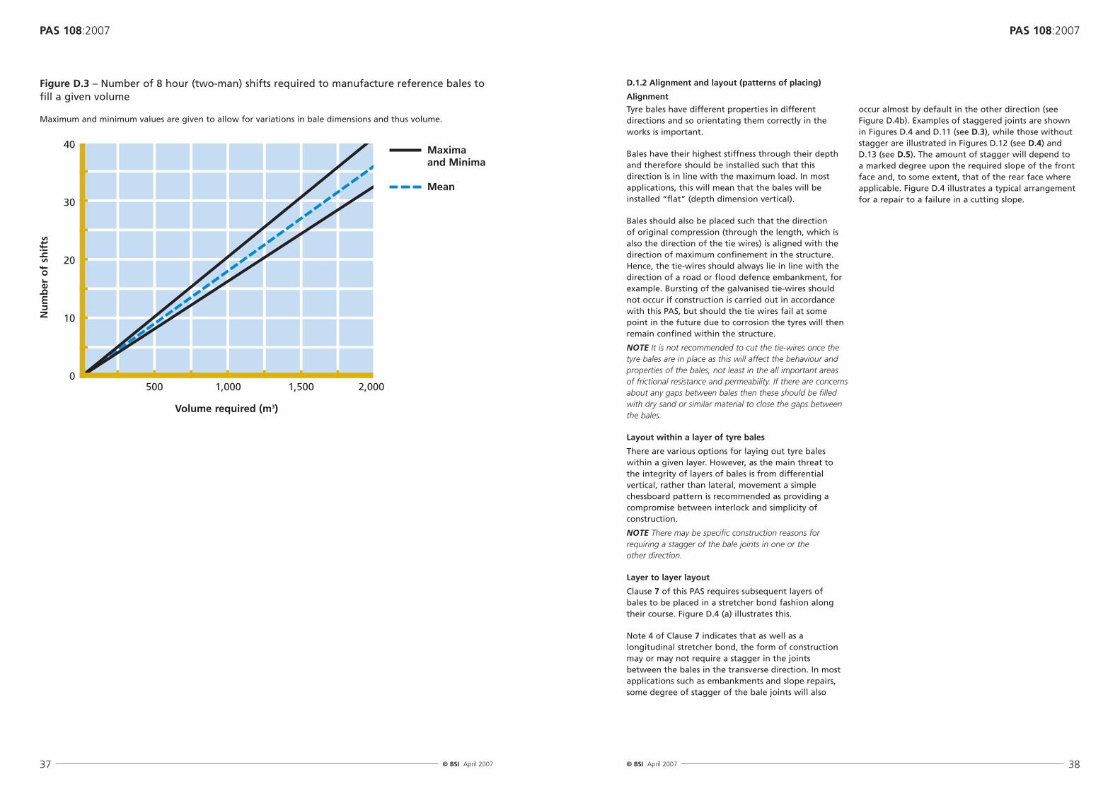
Cost. The manufacturing cost is a function of material,plant and labour at the point of production. Materialquantities can be assessed as above. Plant costs arespecific to the balers being used. An initial assessmentof labour costs can be made using Figure D.3 which isbased on a typical production rate of four bales perhour during a two man shift. The figure gives thenumber of eight hour (two man) shifts required tomanufacture tyre bales of a given volume.
To the production costs need to be added transportand construction costs. The former are minimized bylocating the point of tyre collection and baleproduction as close to the site as possible. However thismay not always be practicable and so alternativemodes of transport should be considered to minimizethe carbon footprint. Unit construction costs aregenerally found to be low due to the simplicity ofplacing the bales.
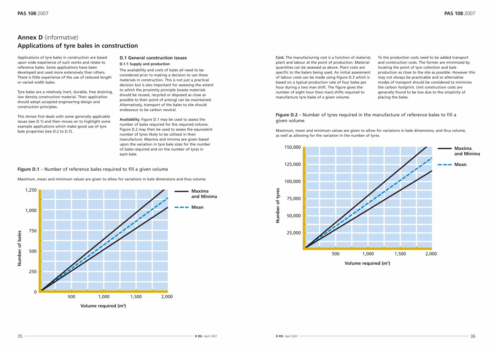
Applications of tyre bales in construction are basedupon wide experience of such works and relate toreference bales. Some applications have beendeveloped and used more extensively than others.There is little experience of the use of reduced lengthor varied width bales.
Tyre bales are a relatively inert, durable, free draining,low density construction material. Their applicationshould adopt accepted engineering design andconstruction principles.
This Annex first deals with some generally applicableissues (see D.1) and then moves on to highlight someexample applications which make good use of tyrebale properties (see D.2 to D.7).
D.1.1 Supply and production
The availability and costs of bales all need to beconsidered prior to making a decision to use thesematerials in construction. This is not just a practicaldecision but is also important for assessing the extentto which the proximity principle (waste materialsshould be reused, recycled or disposed as close aspossible to their point of arising) can be maintained.Alternatively, transport of the bales to site shouldendeavour to be carbon neutral.
Availability. Figure D.1 may be used to assess thenumber of bales required for the required volume.Figure D.2 may then be used to assess the equivalentnumber of tyres likely to be utilised in theirmanufacture. Maxima and minima are given basedupon the variation in tyre bale sizes for the number of bales required and on the number of tyres in each bale.
Annex D (informative)Applications of tyre bales in construction
Figure D.1 – Number of reference bales required to fill a given volume
Maximum, mean and minimum values are given to allow for variations in bale dimensions and thus volume.
500 1,000 1,500 2,000
Volume required (m3)
Nu
mb
er o
f b
ales
Maxima and Minima
Mean
Figure D.2 – Number of tyres required in the manufacture of reference bales to fill a given volume
Maximum, mean and minimum values are given to allow for variations in bale dimensions, and thus volume, as well as allowing for the variation in the number of tyres.
Figure D.3 – Number of 8 hour (two-man) shifts required to manufacture reference bales tofill a given volume
Maximum and minimum values are given to allow for variations in bale dimensions and thus volume.
40
30
20
10
0500 1,000 1,500 2,000
Volume required (m3)
Nu
mb
er o
f sh
ifts
Maxima and Minima
Mean
Tyre bales have different properties in differentdirections and so orientating them correctly in theworks is important.
Bales have their highest stiffness through their depthand therefore should be installed such that thisdirection is in line with the maximum load. In mostapplications, this will mean that the bales will beinstalled “flat” (depth dimension vertical).
Bales should also be placed such that the direction of original compression (through the length, which isalso the direction of the tie wires) is aligned with thedirection of maximum confinement in the structure.Hence, the tie-wires should always lie in line with thedirection of a road or flood defence embankment, forexample. Bursting of the galvanised tie-wires shouldnot occur if construction is carried out in accordancewith this PAS, but should the tie wires fail at somepoint in the future due to corrosion the tyres will thenremain confined within the structure.
NOTE It is not recommended to cut the tie-wires once thetyre bales are in place as this will affect the behaviour andproperties of the bales, not least in the all important areasof frictional resistance and permeability. If there are concernsabout any gaps between bales then these should be filledwith dry sand or similar material to close the gaps betweenthe bales.
Layout within a layer of tyre bales
There are various options for laying out tyre baleswithin a given layer. However, as the main threat tothe integrity of layers of bales is from differentialvertical, rather than lateral, movement a simplechessboard pattern is recommended as providing acompromise between interlock and simplicity ofconstruction.
NOTE There may be specific construction reasons forrequiring a stagger of the bale joints in one or the other direction.
Layer to layer layout
Clause 7 of this PAS requires subsequent layers of bales to be placed in a stretcher bond fashion alongtheir course. Figure D.4 (a) illustrates this.
Note 4 of Clause 7 indicates that as well as alongitudinal stretcher bond, the form of constructionmay or may not require a stagger in the joints between the bales in the transverse direction. In mostapplications such as embankments and slope repairs,some degree of stagger of the bale joints will also
occur almost by default in the other direction (seeFigure D.4b). Examples of staggered joints are shownin Figures D.4 and D.11 (see D.3), while those withoutstagger are illustrated in Figures D.12 (see D.4) andD.13 (see D.5). The amount of stagger will depend to a marked degree upon the required slope of the frontface and, to some extent, that of the rear face whereapplicable. Figure D.4 illustrates a typical arrangementfor a repair to a failure in a cutting slope.
Bales have been placed successfully with, and, withoutfill between the bales. Whether fill should beintroduced depends on the application and the design criteria.
Omitting filling between bales can be advantageouswhen structural rigidity is not critical and has theadvantages of:
• Maximizing the permeability of the tyre bale layer which can be useful in layers with a drainage function.
• Minimizing the load imposed on the underlyingground which can be important when total
settlement of the embankment is critical. Forexample when flood defence embankments areconstructed on soft ground the value of limitinggross settlement may outweigh the disadvantage ofany increased differential settlement (see below).
However, if the gaps between the bales are not filledthen the entire bale structure should be encapsulatedwithin a geosynthetic of suitable form to prevent theingress of the surrounding soil into the bale mass. This approach was adopted on a project on the RiverWitham (see Figure D.5).
D.1.4 Covering of bales (depth and stability of cover)
As required by Clause 7 of this PAS, tyre bales shouldalways be covered at the end of the constructionperiod in order to avoid degradation due to exposureto ultra-violet light. It is also likely that tyre bales will be covered for reasons of aesthetics. A minimumcover depth of 0.5 m of inert fill is recommended. Fine-grained material may be used to help reduce the ingress of water.
The stability of the cover soil should be addressed;where the slope is steep erosion can be a particularproblem, albeit that the stepped nature of anuncovered tyre bale slope aids stability of the cover,limiting the likelihood of larger areas failing.Geosynthetic materials that contain growth media,often described as biosynthetics, can be particularlyuseful in this respect. The range of such materials isconsiderable and independent advice should be soughtin terms of making such a selection. Hessian mats inconjunction with seed mulch have been successfullyused on slopes of up to 1:2. The successful use of such
materials on slopes much steeper than this may requirethe use of sacrificial staples to pin the Hessian mat tothe topsoil.
Such systems are unlikely to be effective for slopes inwhich the soil is placed at angles greater than that ofrepose. Where greater angles are required systemscomprising a steel mesh incorporating a seededbiosynthetic in order to promote vegetation growthmay offer a solution. These are generally formed froma sheet of a horizontal steel mesh attached to a similarsheet set at an angle to the first corresponding to thedesired slope angle. These pre-formed steel meshelements are then placed in layers with the tyre balesin order to form a smooth slope. The same materialused to fill around the bales, with the addition of asmall amount (< 10 %) of organic matter, may then be used to fill the void between the tyre bales and the steel mesh behind the face of the slope. Thevertical dimension of the steel mesh can be specified to match the dimensions of tyre bales makingconstruction simpler.
Filling between bales has several advantages which areimportant when total and differential settlement is tobe minimised (including that under vertical loading):
• Maximising the friction between the bales byminimising the effect of the joint gaps between thebales caused by the slight curvature at the edges andcorners of the bales. This has the dual benefits of:
• Maximising the internal stability of the bale mass, and
• Helping to reduce differential settlement betweenadjacent bales.
• Minimising the potential for the surrounding soil tobe washed into these same gaps.
• Reducing any long term creep settlement of the balestack (see C.2.8).
For these reasons filling between the bales isparticularly important for structural applications inwhich the friction and interlock between the balesmust be optimised (usually maximised), for example in transport infrastructure embankments.
Guidance on the amount of material required to fillthese gaps is given in Box D.1.
The material used to fill the gaps must be acompromise in terms of its properties between beingable to flow freely into the gaps, exhibiting frictional
strength and being able to drain freely. Coarse sandand fine gravel have been found to be good materialsfor this use. The addition of water in excess of theoptimum moisture content is sometimes useful topromote the free flow of the material into the gaps,provided that suitable drainage exists for excess waterto escape. Placement of fill between layers of tyrebales should be avoided (except for the occasionalregulating layers described below). This avoids thepotential to create a preferential slip plane betweenthe layers of bales (and also minimises the amount offill required).
Depending on the form of structure, the key designconsiderations, and the grading of both the fill and theadjacent soil, the entire bale structure may need to beencapsulated within a geosynthetic of suitable form toprevent the ingress of the surrounding soil into thebale mass and to further limit differential settlement.
Regulating layers take up the cumulative minorirregularities which develop in the surface of the tyrebale layer when a significant number of bale layers are involved. It is therefore suggested that if fillingbetween bales within layers is acceptable, anadditional regulating layer of 200 mm to 400 mmdepth should be placed between each “lift” of 3 or 4tyre bale layers.
It is estimated that the gaps between the bales take up between 4 % and 8 % of the volume of a massof bales.
The density of the resultant bale mass, ρM, with void filling will be different to that of the balesthemselves and, given the above, lies between:
and
where
ρTr the true bale mass density (as opposed to that of the enclosing cuboid) varies between 430 kg/m3
and 570 kg/m3,
and
ρF is the mass density of the fill used.
Thus taking the density of the fill between the bales, ρF , to be 1,600 kg/m3 the density of the tyre balemass, ρM , will increase to between 480 kg/m3 and 650 kg/m3.
Clearly this does not take account of any additional fill placed in regulating layers. However, similarprinciples may be used to calculate the bale-fill density in these circumstances.
Box D.1 – Filling gaps between bales: quantity and density implications
In areas of deep soft soil, full replacement techniquesare unattractive as large volumes of material must be excavated, transported and disposed of with theconsequential effect on costs. Additionally, thesurrounding soft material may create technicaldifficulties related to excavation support, basal heaveand other factors, making the proposed projectdifficult if not uneconomic.
Where the natural surface ‘crust’ is stiffer than thelower layers due to vegetation, desiccation,compaction and other factors the surface may besuitable for use as the road foundation. Care is needed to ensure that the crust is not broken orotherwise compromised during construction and thatas the road is built the imposed loads are spread overas wide an area as practical. Historically, variousmaterials have been used to enhance the ‘crust’ effectand spread loads. The shallow embankment on whichthe Airedale Railway runs through Bingley in Yorkshireis constructed over a peat bog with bundles of faggotsand sheep pelts placed on top of the peat to spreadthe load of the embankment.
Above ground construction has often utilized bundlesof twigs, called fascines, placed at subgrade level toprovide resistance to differential movement. Oftenthese were orientated at 90° to one another in twolayers. On constructions designed to take higher trafficflows logs and timber grillages were used above thefascines. This generally worked best where a stiffermaterial, such as fibrous peat, overlay less competentmaterial, such as amorphous peat. The modernequivalent is a geosynthetic material often with a sandregulating layer. The use of tyre bales on top of thegeosynthetic/sand layer allows the applied load to beminimized.
The removal of in-situ materials and replacement withnew, preferably lightweight, materials is undoubtedly a more expensive option. However, due to the lateralrestraint provided by the excavation boundaries a more durable construction is likely. The key to suchconstruction lies in ensuring that the new materialadds as little load as possible.
Buried construction may be preferred in morecompetent materials, or shallow poor materials forwhich removal is an option. Such materials includenormally consolidated silts and clays, and softpredominately mineral soils for example. A geotextileis a key element in ensuring that the subsoil isseparated from the tyre bale construction, thuspreventing pumping, and the potential for differential
settlement between adjacent bales is minimized, inparticular under construction loads.
The repair or reconstruction of an existing road oversoft ground presents particular problems. Often therepair is required as a result of differential settlement.The road materials will have settled giving an unevensurface, poor ride quality and an increased risk offlooding. The placement of additional material to raiseand regulate the pavement surface is simple but willincrease the loading on the formation and almostcertainly cause additional differential settlement. Thereplacement of the existing material is thus a necessity.
Typical cross-sections for buried and floatingconstruction are illustrated schematically in Figure D.7.
When placing bales without filling of the gapsbetween them, it may be appropriate to consider theplacement of short breaks in the longitudinal balecourses formed using frictional fill. The fill is to beplaced with each course in such a way as to maintainthe stretcher bond pattern and typically will be oflongitudinal dimension half to one times the length ofa tyre bale. The reasons for considering this break arepartly to correct unevenness in the stretcher bondpattern that may have developed over a length of, say,100 m. They can also provide reassurance to thoseconcerned about the potential for arson duringconstruction as they will provide a natural fire break.
D.2 Road foundations over soft ground
Tyre bales can provide lightweight foundations toroads over soft ground. They can be particularlyeffective in situations where the layer of soft materialis sufficiently thick that solutions involving the removaland replacement of its full depth are impractical oruneconomic. Many roads over soft ground allow accessto remote and relatively under-populated regions andas a result carry relatively little traffic and musttherefore be constructed and maintained withinlimited budgets.
There are essentially two approaches to construction of roads over soft ground: above ground or ‘floating’construction and below ground construction (Figure D.6). Both conventionally use large volumes of granular fill.
Figure D.6 – Schematic illustrating the differences between ‘floating’ and buried construction
Floating Construction
• Mass of construction is additive• Risk of settlement• Surface ‘crust’ remains intact
Buried Construction
• Mass of construction may not be additive
• Lesser risk of settlement• Surface ‘crust’ breached
D.2.2 Other design and construction considerations
Experience of tyre bale road foundations is limited toannual average daily traffic (two-way) levels of 200 to 1,600 vehicles per day. However there seems littlereason to restrict their use in carefully engineered, low risk projects subject to traffic levels of < 5,000vehicles per day.
Whether floating or buried construction is adopted it is important that the bales are properly aligned andlaid out as described in D.1.2. Filling between the balesis required in order to provide maximum stability andresistance to differential settlement (D.1.3), as is theuse of a suitable geosynthetic beneath the bales.Consideration should also be given to wrapping thegeosynthetic around the entire bale mass.
The required form of road pavement construction willbe constructed on top of the bales; typically this maybe between 250 mm and 450 mm thick.
The design of the surface and subsurface drainage ofthe construction will be determined by the prevailingclimate and construction specifications in the locationin which the road is constructed. In the case of fullybound surfaces local specifications will determine bothtypes of drainage. In the case of unbound surfaces lessinformation may be available and as the custom isoften to construct such road pavements wider thantheir bound equivalents this must be taken account of in the design of the edge drainage, the subsurfacetransverse fall and the surface cambers or crossfall.
D.3 Slope failure repairSlope failures and landslides occur in five basic modes:falls, topples, slides, flows and spreads. A sixth mode,‘complex failures’, involves one of the five types ofmovement following another type (or types), rock fall-debris flow for example.
Typical approaches to the remediation of failed soilslopes include:
• The placement of mass at the toe;
• The placement of soil nails, anchors or piles tostrengthen the in-situ material;
• Construction of a retaining wall (including gabionand crib walls) to resist further movement of the in-situ material;
• The use of geosynthetics to strengthen either the in-situ material or replacement fill;
• Stabilisation, or solidification, of the in-situ material;
• Drainage improvement;
• Replacement of the in-situ material with stronger,better draining fill.
Not all types of slope failure lend themselves toremediation using tyre bales. The essential feature that determines the suitability of tyre bales for use in slope failure remediation is the presence of a largevoid, usually created by the movement of the failedmaterial. Often this material will need to be excavatedto fully reveal the extent and shape of the failure (e.g. Figure D.8). The role of water is usually critical in the creation of failures and, thus, the voids thatresult from the excavation of the failed material. This is demonstrated by the fact that free-draining rockfill is often used to improve the subsequent drainage(Figure D.9) and hence free-draining tyre bales offer a natural alternative.
Typically, slides (in circular, translational or wedgeform) will involve the movement of relatively largevolumes of material. Such volumes of failed materialwill often be removed to create a large void which isthen filled as part of the remediation works (FigureD.8). The object of such excavation and replacementworks is to reform the slope using a higher strength,freer-draining material. Flows may also produce largevoids as gullies may be formed or enlarged during theirerosional phase (Figure D.9). Slides and flows aretherefore most likely to provide an environment inwhich the high inter-bale friction angle and highpermeability of tyre bales may be exploited in slopefailure remediation. In general failures in rock slopesare much less likely to lead to situations favouring theuse of tyre bales in their remediation.
Filling of the gaps between the bales is stronglyrecommended in order to maximise the stability of thebale mass. Before completing the surface protection, it is also recommended that the face of the tyre bale
The boundary details are particularly important interms of promoting the appropriate flow of water intoand out of the tyre bale mass and also in ensuring thatthe high permeability bales do not cause ponding andconsequent softening of the adjacent soil materials.
The base, sidewalls and back wall of the excavationmust be constructed so as to promote both stabilityand the flow of water out of the mass of tyre bales in a controlled manner so as not to introduce furtherproblems elsewhere.
The base of the excavation should be constructed so as to slope downwards toward the toe of the slopeand the shape of the excavation can be relied upon toprovide passive drainage (Figure D.10). Whilst a basesloping towards the toe of the slope is likely to yield a slightly less stable repair compared to an inwardsloping base, the drainage arrangement is considerablyless complex and will require much less maintenance inthe longer term. The precise angle of the slope of thebase of the excavation will be dictated by the needs ofeach situation and it is likely that a number of angleswill be analysed to assess the influence of excavationbase angle on the overall stability of the slope.
The lateral gradient of the base of the excavationshould be constructed so as to ensure that water flowsto one end. This water needs to be collected and
removed so as not to promote instability in theadjacent slope. At the low end of the excavation aperforated pipe should be used to collect the waterand provide gravity drainage to the main roaddrainage system. This approach largely avoids the needfor a ‘water stop’ at the end of the excavation.
Typically the boundaries will be formed by a suitablegeosynthetic fabric overlain by a minimum of around150 mm of free-draining fill between the bales andeach boundary. These materials should be selected tominimize the migration of in-situ soil into the repair.
A typical solution involves the stacking of tyre baleswithin the void (Figure D.11). The directionaldependence of their permeability indicates that care isrequired in placing bales to ensure that the flow isoptimised. It should also be noted that while thepermeability of tyre bales is somewhat lower than forrockfill the porosity is likely to be equivalent or higher.
The maximum permeability will usually be orientedvertically and the depth of the bale placed vertically.This also means that the tie wires will be parallel to the face of the slope, so as to maximize confinement.However, if drainage is critical then consideration toaligning the bales with the tie-wires perpendicular tothe slope can be given in order to maximize the flowof water out of the slope.
Figure D.9 – A gully eroded by the action of a debris flow
Drainage path
Figure D.11 – Schematic cross-section showing a typical layout of a slope failure repair
Crossfall to promote drainage from within tyre bale mass to edge drains
Drainage to external system
Geosynthetic
fill is covered with a suitable geosynthetic fabric tohelp prevent the penetration of roots into the tyrebale mass.
Figure D.10 – Schematic diagram of excavation showing the drainage paths for the base ofthe excavation sloping towards the toe of the slope
Embankments across low-lying soft ground arecommonly required for transport, services and flooddefence. Their height means that they apply asignificant loading to the underlying soft ground,which can lead to significant total and differentialsettlements and potential failures of either the groundor the embankment and resulting ongoingmaintenance expenditure.
There are a number of ways in which settlement maybe limited, including the following:
• Reducing the weight of the embankment.
• Staged construction and/or pre-loading of theembankment to allow subsoil consolidation.
• Reinforcing the base of the embankment to helpspread the load better.
• Constructing the embankment on piles, or stone orlime/cement columns.
• Improving the foundation soil by mechanical orchemical means, by accelerating the drainage, bypre-loading, or by dewatering.
Whichever solution is adopted, drainage, especially at the base of the embankment, remains a critical issue in ensuring stability of both the embankmentitself and the underlying soft ground, such as floodplains, marshes and peat bogs. Tyre bales, being bothlightweight and free-draining, have considerablepotential to form a critical construction material forembankments both on soft ground and more widely.The bulk unit weight of an embankment comprising a tyre bale core may reduce the vertical stress on thesubsoil by a considerable amount (well in excess of 50 % in many instances), and their use provides avaluable advantage to the engineer.
Tyre bales can be used in both new construction and in repairs or modifications to existing embankments(see D.3 for slope repair). In the design andconstruction, full account should be taken of thefoundation conditions and the requirements for freedrainage of the tyre bales. Construction will typicallycommence with a geosynthetic fabric overlain about150 mm of free-draining fill between the bales andeach boundary. After placement of the bales, the gaps between them are filled with gravel. Beforecompleting the surface protection, the resulting balestack is covered with a further geosynthetic fabric.
Many of the key issues discussed in D.2 in relation toroad foundations over soft ground are also importantto the design and construction of embankments. Inparticular, the issue of floating versus buried
construction is still more critical for embankmentsconstructed on soft ground. Burying the first layer oftyre bales has the potential to provide some lateralsupport and this approach is reflected in Figure D.12.Implicit within the assumptions under-pinning thisapproach is that the side walls of the excavation willnot fail during the brief construction period. However,embankments are likely to impart significantly higherloads than roads constructed more or less at grade andin many cases buried construction may beinappropriate. Geosynthetics should be specified inorder to provide separation between the existingground and to provide resistance to the tendency ofthe bales to separate under load whether buried orfloating construction is used. This will help to resist the lateral stresses developed at the base of theembankment during the consolidation stage and willresist the formation of ‘slips’ within the embankment.
Designs of embankments must assess both internal and external stability – that is, they must consider both the stability of the embankment itself and themagnitude of the settlement induced by the loadsapplied by the embankment in the underlyingformation. The provision of basal reinforcement also should be a key consideration.
Figure D.12 – Schematic cross-section showing typical layouts of tyre bale embankments: (a) buried construction; and (b) floating construction.
Cambers to enable water to be shed
Transverse falls to promote drainage from within tyre bale mass to edge drains
As for all retaining walls it is essential that particularattention is paid to the design and construction of thedrainage from the back to front faces of the wall. Formost walls this takes the form of weep holes, but intidally affected locations flap-valves may be required to prevent the ingress of tidal water.
The installation of tyre bales does not obviate the needfor the designer to consider whether a wedge ofgranular material will be needed behind the bales tofurther relieve the active pressures behind the wall.
D.6 Drainage layers, including in landfill engineeringDrainage layers are required in many types ofstructures including embankments and landfill cells.The high permeability and easy handling of tyre balesmakes them ideally suited to such applications.
Figures D.7, D.11 and D.12, illustrating roadfoundations, slope repairs and embankments allincorporate and illustrate the use of drainage layers,particularly in the form of the lowest layer in the caseof slope repair and embankments. For many
applications the information provided in D.2, D.3 andD.4 will be relevant.
When using the bales attention should be given to theanisotropic nature of their permeability, the greatestpermeability arising through the depth of the bales.
Filling of the gaps between the bales will depend uponthe design requirements of the structure underconsideration; situations in which the gaps betweenbales would either need to be filled or left open can beenvisaged for drainage layers. Geosynthetic fabrics willgenerally be placed above and below the drainagelayers to limit ingress and subsequent blockage of thetyre bales by fine material.
Tyre bales are beginning to be used in the basaldrainage layer for landfill sites. For landfill applicationsthe loads on the basal drainage can be significant withmany metres of fill albeit of lower density than soils.These represent probably the largest loads under which tyre bales are being used to date. Figure D.14illustrates tyre bales being placed in a landfill drainage layer.
Provision for drainage of the subsoil will probably berequired, and may be achieved using band drainsand/or by utilising the lowest layer of tyre bales as a drainage layer beneath the embankment.
Fill to the gaps between bales is likely to be required if the embankment is designed to carry infrastructuresuch as road and other elements that will imposeserviceability limits on differential settlements. Forflood embankments where the serviceability criteria for differential settlements are more relaxed,minimising the loads applied to the subsoil may be a more important issue and in such cases it may bedesirable to omit the fill around the bales.
D.5 Free-draining layers behind retaining wallsRetaining walls can be a challenge to design wheresubstantial heights of ground or fill have to besupported (e.g. in port construction). When placed
behind the wall, tyre bales can provide a free draininglayer which avoids excessive water pressures frombuilding up behind the wall. They may also assist by reducing the load applied to some forms of wall construction.
The form of construction will involve stacking balesdirectly behind the wall, providing a geosynthetic filterbetween the bales and the subsequent backfill. Carefulconsideration is needed as to whether it is appropriateto allow imposed loading at the level of the top of thewall, given the impact this may have on settlement anddrainage behaviour.
Figure D.13 illustrates possible arrangements for tyrebales for three widely used retaining wall types. Theuse of an appropriate geosynthetic material wrappedaround the tyre bale mass is essential to act as a filterto the ingress of fines from the surrounding material.
Figure D.13 – Schematic cross-sections showing typical layouts for free-draining tyre balelayers behind retaining walls: (a) sheet pile wall; (b) anchored sheet pile wall; and (c) gravityretaining wall
Figure D.14 – Tyre bales being placed in a leachate drainage layer at the base of a landfillcell at Bryn Posteg
The issue of what happens to tyre bales at the end ofthe service life of the structure of which they form apart is as important as for any other material. Clearlyany disposal at a later date due to demolition forexample will be determined by the prevailinglegislation, regulation and interpretation thereof atthat time. As with all construction components thepresence of tyre bales should be noted in the Healthand Safety file required by the Construction (Designand Management) Regulations 1994 and anyanticipated approaches to reincorporation and/orremoval noted. The management of any balesemerging at the end of service life must be appropriate but clearly forms of recovery involvingboth engineering and non-engineering uses could be considered.
There is no evidence of significant deterioration oftyres buried in the ground, even after many years.However effective reuse will be more convenientlyachieved if the bales are uncontaminated with fine orclayey material. This is most readily achieved where thebale stacks or layers have been covered with a suitablegeosynthetic fabric as part of the original construction.The bales can then be reused in any application inother structures, so long as the tie wires are intact.Should the tie wires not be intact then considerationcould be given to re-baling the tyres on site, albeit thatthis will add to the overall cost of the operation.
However, incorporating the bales into anyreconstruction in the same location is likely to be themost attractive and cost-effective option. Some optionsare briefly discussed below:
E.2 Road foundations over soft groundIn the example of a road construction that is to berefurbished the existing bales could be used as aconstruction platform for the reconstruction. Such anapproach is most likely to succeed if the tyre bales areplaced lower in the original carriageway so that theycan form the foundation in the reconstruction.
E.3 Slope failure repair and lightweightembankment fillTyre bales incorporated into slope failure repairs orlightweight embankment fill are only likely to beremoved in the event of failures, where widening orrealignment of any associated infrastructure is
required, or there is a need to remove part or all of anembankment. Leaving the bales in place is likely to bethe preferred option, but if they have to be removedthey can be re-employed in the further slope orembankment construction that will inevitably berequired in such situations.
E.4 Free-draining lightweight layers behindretaining wallsRetaining walls are rarely demolished, it being more common to install additional walls in front ifstrengthening or height increases are required. In suchsituations the bales can be left in place. Where wallsare demolished, it will commonly be in the context ofconstruction of further infrastructure and the balesshould be reused therein.
E.5 Drainage layers and Sustainable UrbanDrainage Systems (SUDS)The decommissioning of drainage and SUDSinfrastructure is likely to be highly specific to the typeof works originally installed. As a starting point themanagement of such decommissioning works shouldassume that the tyre bales will be reused withoutbeing removed form their present location. However,in a significant number of cases this is unlikely to befeasible, but they should be reused in further works in the vicinity.
Sustainable Urban Drainage Systems (SUDS) are thosewhich limit amounts and rates of discharge of waterfrom housing and industrial developments into watercourses, encouraging recharge of water back intoaquifers. Tyre bales are suited to some SUDS systemsbecause of their permeability and porosity. In suchapplications, the high porosity of the bales is importantas it permits storage of significant quantities of waterslowing eventual discharge and encouraging filtrationinto the surrounding ground.
Many applications to SUDS can be envisaged, such as soakaways, French drains and under permeable car park paving for temporary water storage.Geosynthetics will be needed to limit ingress andsubsequent blockage of the tyre bales by fine material.
Figure D.15 illustrates a typical layout for a tyre bale soakaway.
Figure D.15 – Schematic cross-section showing a typical layout a tyre bale soakaway
GeosyntheticInlet pipeDrain
Silt trap Sand surround
Coarse gravel
Annex E (informative)Applications of tyre bales in construction
D.7 Sustainable Urban Drainage Systems (incl. soakaways)
Standards publicationsBS EN 10244-2: 2001, Steel wire and wire products –Non-ferrous metallic coatings on steel wire – Part 2:Zinc or zinc alloy coatings.
BS EN 10270-1: 2001, Steel wire for mechanical springs– Part 1: Patented cold drawn unalloyed spring steel wire.
[3] GREAT BRITAIN. The Management of Health andSafety at Work Regulations 1999 London: TheStationery Office.
[4] GREAT BRITAIN. The Provision and Use of WorkEquipment Regulations 1998. London: The StationeryOffice.
[5] GREAT BRITAIN. The Personal Protective EquipmentWork Regulations 1992. London: The Stationery Office.
[6] GREAT BRITAIN. The Construction (Design andManagement) Regulations 1994. London: TheStationery Office.
Additional Reading Aaboe, R, Haoya, A-O, Edeskar, T (2004). Leaching ofPhenol from tire shreds in a noise barrier. Used/Post-Consumer Tyres, 251-260. Thomas Telford, London.
Anon (2003). Geotechnical investigation and analyses –slope failure repair utilizing baled tire fill, InterstateHighway 30 west of Oakland Blvd., Fort Worth, TarrantCounty, Texas. Report by TEAM Consultant Inc to FortWorth District, Texas Department of Transportation.Forth Worth, TX: Texas Department of Transportation(www.dot.state.tx.us/).
Collins, K J, Howell, D and Fisher, N (2004). Tyres incoastal and flood defence engineering – environmentalmonitoring. Sustainable Waste Management. ThomasTelford, London
Collins, K J, Jensen, A C, Mallinson, J J, Roenelle, V andSmith, I P (2002). Environmental impact assessment of ascrap tyre artificial reef. ICES Journal of Marine Science,59: S243-S249.
Collins, K J, Jensen, A C, Mallinson, J J, Smith, I P,Mudge, S M and Russel, A (2001) Scrap tyres for marineconstruction: Environmental impact. Recycling andReuse of Used Tyres, 149-162. Thomas Telford, London.
Hylands, K N and V Shulman (2003). Civil engineeringapplications of tyres. Viridis Report VR5. Crowthorne:TRL Limited.
Prikryl, W, R Williammee and M G Winter (2005). SlopeFailure Repair using Tyre Bales at Interstate Highway30, Tarrant County, Texas, USA. Quarterly Journal ofEngineering Geology and Hydrogeology, 38(4), 377-386.
Reid, J M and M G Winter (2004). The use of post-consumer tyres in civil engineering. Used/Post-Consumer Tyres, 195-202. London Thomas Telford.
Simm, J D, M J Wallis and K Collins (2005). Sustainablere-use of tyres in port, coastal and river engineering:guidance for planning, implementation andmaintenance. HRW Report SR 669. Wallingford: HRWallingford.
Simm, J D, M J Wallis, K J Collins and R Atkins (2004).Reuse of materials in coastal and river engineering.
Proceedings, Institution of Civil Engineers (EngineeringSustainability), 157(ES3). 113-121.
Winter, M G (2005). Report on a Technical Visit to theUnited States of America: May 2004. The Delegate,Issue 45 (March) London: Royal Academy ofEngineering (www.raeng.org.uk/).
Winter, M G, P E Johnson and J M Reid (2005).Construction of road foundations on soft ground usinglightweight tyre bales. Problematic Soils, 2, 775-783.Famagusta, N Cyprus: Eastern Mediterranean UniversityPress.
Winter, M G, J M Reid and P I J Griffiths (2005). Tyrebales in Construction: Case Studies. TRL PublishedProject Report PPR 045. Crowthorne: TRL Limited.
Winter, M G, G R A Watts and P E Johnson (2006). Tyrebales in Construction. TRL Published Project Report PPR080. Crowthorne: TRL Limited.
Zornberg, J G, B R Christopher and C J LaRocque(2004). Applications of tire bales in transportationprojects. Recycled Materials in Geotechnics (Eds: A HAydilek and J Wartman). Geotechnical SpecialPublication No 127, 42-60. Baltimore, MA: AmericanSociety of Civil Engineers.
Zornberg, J G, B R Christopher and M D Oosterbaan(2005). Tire bales in highway applications: feasibilityand properties evaluation. Research Branch Report No.CDOT-DTD-R-2002-2 (in two volumes). Denver, CO:Colorado Department of Transportation(www.dot.state.co.us/).
In addition to these references, The Waste Resources & Action Programme (WRAP) websites for aggregates(www.aggregain.org.uk/) and tyres(www.wrap.org.uk/materials/tyres/) contain a largenumber of case studies of practical constructionprojects utilising tyre bales.
BSI is the independentnational body responsible forpreparing British Standards. It presents the UK view onstandards in Europe and atinternational level. It isincorporated by Royal Charter.
RevisionsBritish Standards are updated byamendment or revision. Users of British Standards should make surethat they possess the latestamendments or editions.
BSI offers members an individualupdating service called PLUS whichensures that subscribers automaticallyreceive the latest editions of standards.
Buying standardsOrders for all BSI, international andforeign standards publications shouldbe addressed to Customer Services.
Tel: +44 (0)20 8996 9001Fax: +44 (0)20 8996 7001Standards are also available from the BSIwebsite at http://www.bsi-global.com.
In response to orders for internationalstandards, it is BSI policy to supply theBSI implementation of those that havebeen published as British Standards,unless otherwise requested.
BSI – British Standards Institution
Information on standardsBSI provides a wide range ofinformation on national, European and international standards through its Library and Technical Help toExporters Service. Various BSI electronicinformation services are also availablewhich give details of all its productsand services.
Contact the Information CentreTel: +44 (0) 20 8996 7111Fax: +44 (0) 20 8996 7048Email: [email protected]
Subscribing members of BSI are kept up to date with standardsdevelopments and receive substantialdiscounts on the purchase price ofstandards. For details of these andother benefits contact MembershipAdministration.
Information regarding online access toBritish Standards via British StandardsOnline can be found at http://www.bsi-global.com/bsonline
Further information about BSI isavailable on the BSI website athttp://www.bsi-global.com
CopyrightCopyright subsists in all BSIpublications. BSI also holds thecopyright, in the UK, of thepublications of the internationalstandardization bodies.
Except as permitted under thecopyright, Designs and Patents Acts1988 no extract may be reproduced,stored in a retrieval system ortransmitted in any form by anymeans – electronic, photocopying,recording or otherwise – withoutprior written permission from BSI.
This does not preclude the free use,in the course of implementing thestandard, of necessary details suchas symbols, and size, type or gradedesignations. If these details are tobe used for any other purpose thanimplementation then the priorwritten permission of BSI must be obtained.
Details and advice can be obtained from the Copyright & Licensing Manager.