SPECIFICATION NO.MMC/MSC-II/GIS/18/10/2017 Page 1 of 52 SPECIFICATION NO.MMC/MSC-II/GIS/18.10.2017 TECHNICAL SPECIFICATION For 33 KV,22 KV& 11 KV Gas Insulated Switchgear A) 33 KV,22 KV Switchgear in SF6, Busbar in SF6 or Silicon coated and 11 kV Switchgear in SF6, Busbar in SF6 or Silicon coated. OR B) 33 KV,22 KV Switchgear in SF6, Busbar in SF6 or Silicon coated and11 kV Air Insulated Switchgear & Busbar. FOR DISTRIBUTION SYSTEM IN MSEDCL
Transcript
SPECIFICATION NO.MMC/MSC-II/GIS/18/10/2017
Page 1 of 52
SPECIFICATION NO.MMC/MSC-II/GIS/18.10.2017
TECHNICAL SPECIFICATION
For
33 KV,22 KV& 11 KV Gas Insulated Switchgear
A) 33 KV,22 KV Switchgear in SF6, Busbar in SF6 or Silicon coated and 11 kV Switchgear in SF6, Busbar in
SF6 or Silicon coated.
OR
B) 33 KV,22 KV Switchgear in SF6, Busbar in SF6 or
Silicon coated and11 kV Air Insulated Switchgear & Busbar.
FOR
DISTRIBUTION SYSTEM
IN
MSEDCL
SPECIFICATION NO.MMC/MSC-II/GIS/18/10/2017
Page 2 of 52
INDEX
CLAUSE
NO.
PARTICULARS. PAGE.
1.0 Scope 4
2.0 Objective of work & Tolerance 4
3.0 Service conditions 5
4.0 Reference Standards 5
5.0 General technical requirements. 8
5.1 Switchgear Panel 8
5.2 11kv indoor AIS switchgear panel 8
6 Busbar and Insulators 10
7 Circuit Breaker 12
8 Disconnector and earthing switch 13
9 Control and Interlocks 13
10 Earthing and Earthing Devices
14
11 Current transformers 15
12 Potential transformer 15
13 Power cable termination
16
14 Low voltage Compartment (Instrument Chamber) 16
15 SCADA Compatibility 17
16 Numerical Protection Relays (IEDs) 17
17 Control & Protection System
18
18 Numerical Transformer Protection Relay 18
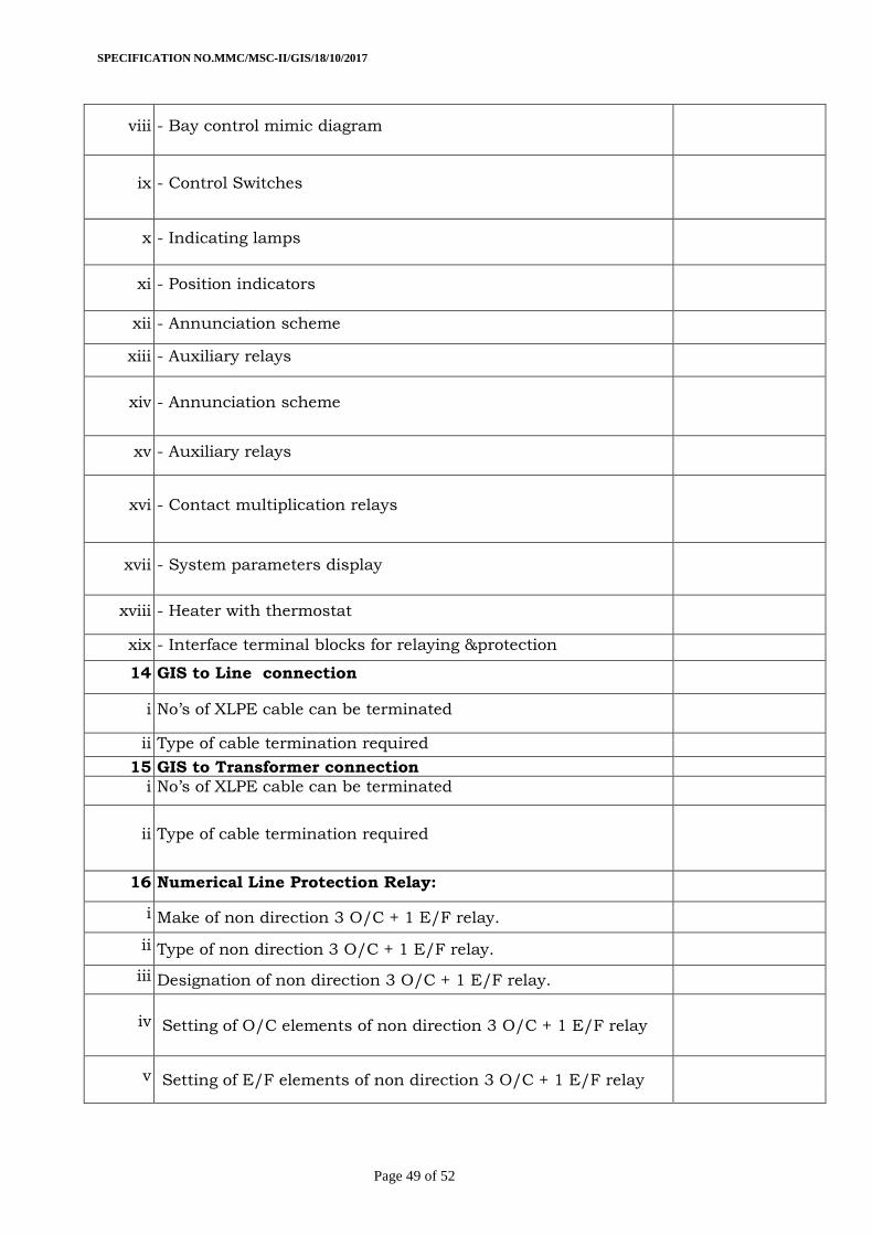
19 Numerical Line Protection Relay: 19
20 Numerical Bus Coupler/Bus-Section Protection Relay: 19
21 Other Control and Protections features
19
22 Ethernet switch
20
23 General requirement for erection. 20
24 Control wiring 20
25 Wiring and control wiring terminals
21
26 Bill of material for 33kV / 11kV & 22/11 KV, 2 x 10 MVA Substation
21
27 System parameters 24
28 Input signal to sas (statistical analysis system) system 28
29 Scheme features:
29
30 Annunciator
29
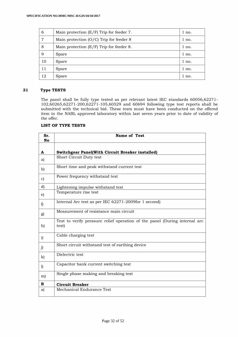
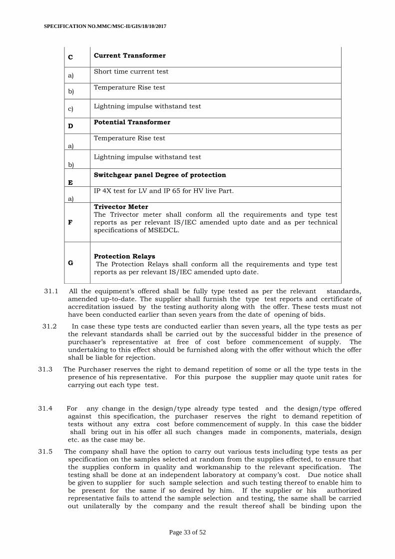
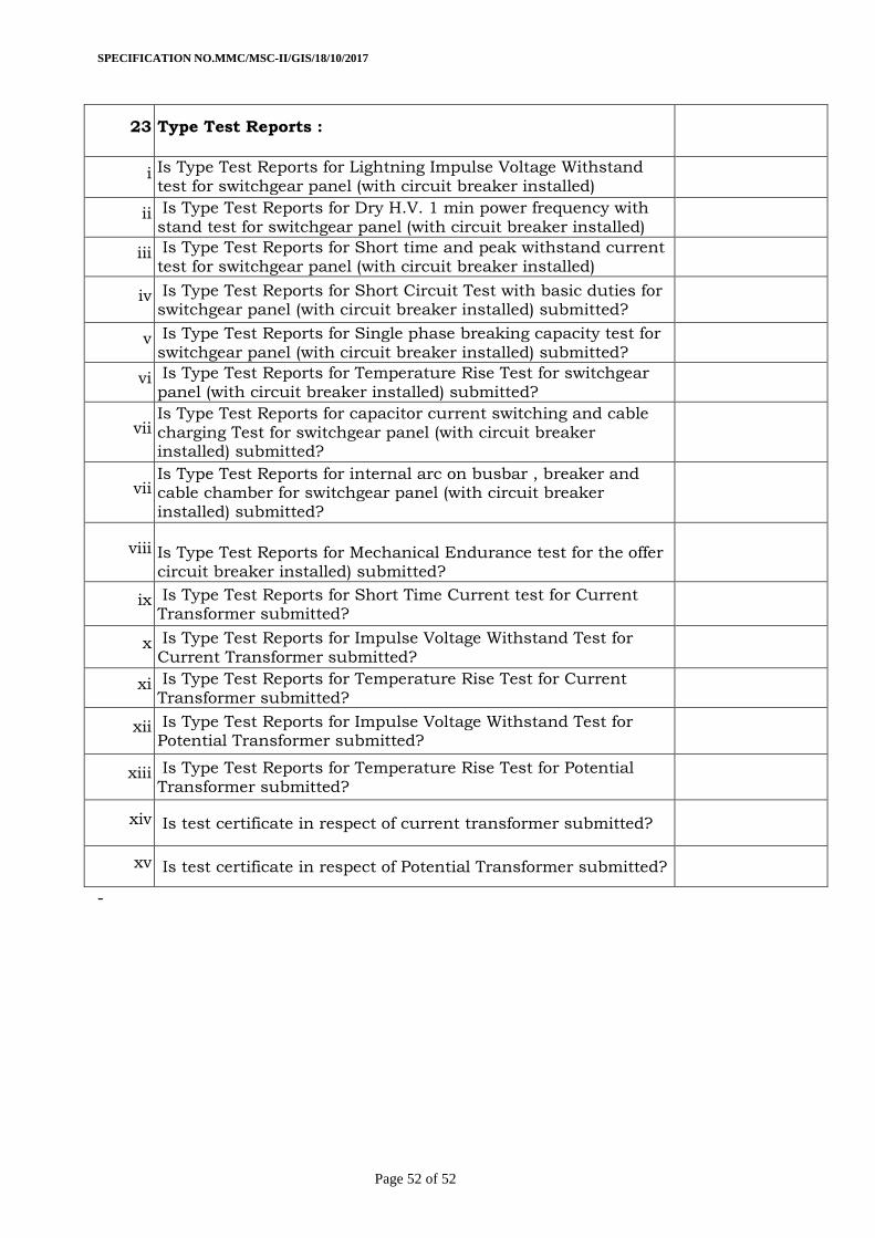
31 Type TESTS
32
SPECIFICATION NO.MMC/MSC-II/GIS/18/10/2017
Page 3 of 52
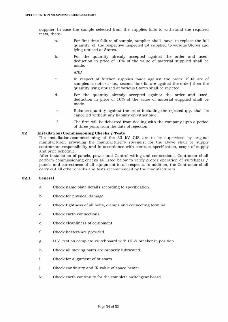
32 Installation/Commissioning Checks / Tests 34
33 Inspection 36
34 Factory acceptance & routine tests:
36
35 Quality assurance plan 37
36 Performance guarantee 37
37 Documentation 37
38 Drawings 37
39 Packing and forwarding 38
40 Supervisory erection and commissioning 39
41 Training to the MSEDCL staff 39
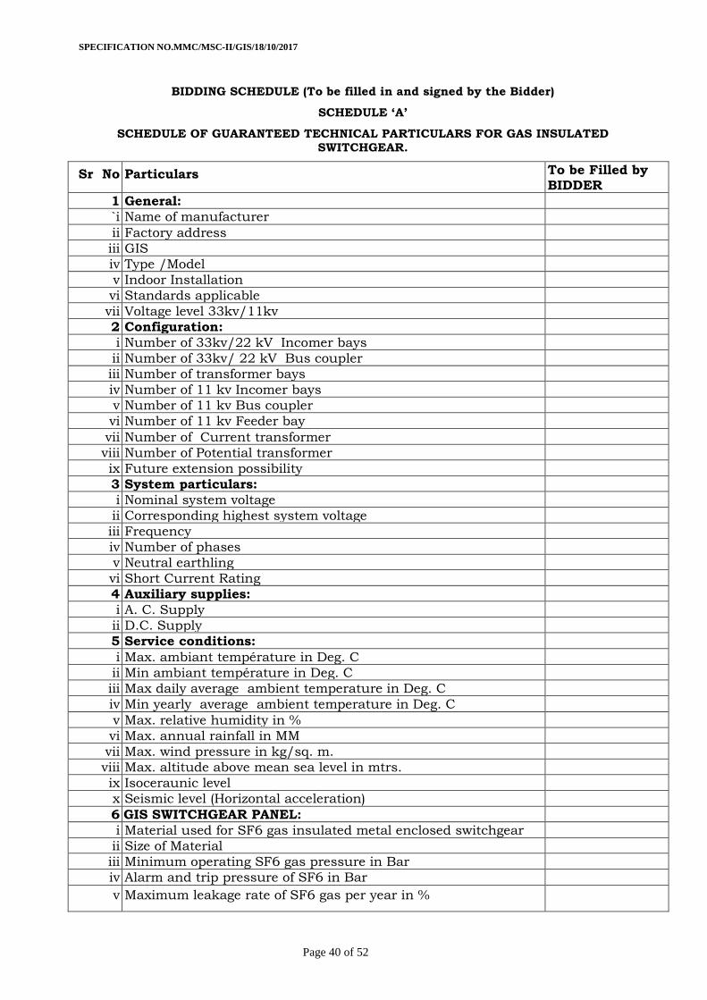
Guaranteed technical particulars 40
SPECIFICATION NO.MMC/MSC-II/GIS/18/10/2017
Page 4 of 52
Technical Specifications for A) 33 KV,22 KV Switchgear in SF6, Busbar
in SF6 or Silicon coated and 11 kV Switchgear in SF6, Busbar in SF6 or Silicon coated B)33 KV,22 KV Switchgear in SF6, Busbar in SF6 or Silicon coated and 11
kV Air Insulated Switchgear & Busbar
1.00Scope:
1.1. This specification covers design, manufacture, assembly, testing before supply, inspection,
packing and delivery of metal clad partitioned,SF6 gas insulated switchgear confirming to IEC-
62271-200.The GIS type switchgears shall be complete with all the accessories and auxiliary
equipment’s required for their satisfactory operation such as switchboard panels for line bays,
bus coupler/bus section bays etc. shall be fitted with vacuum circuit breakers, three position disconnector and earthing switches, voltage transformers, current transformers, metering
feeders etc. as per forgoing specification in various sub-stations of the MSEDCL.
1.2. It is not the intent to specify, completely here in all the details of design and construction of
the GIS type Switchgear. However, the switchgear shall conform, in all respects to high
standards of engineering, design and workmanship with recent editions. It shall be capable of performing in continuous commercial operation up to the supplier's guaranteed
life of equipment in a manner acceptable to the purchaser who will interpret the meanings
of drawings and specifications and shall have power to reject any work or material which, in
his judgment, is not in accordance therewith. The switchgear offered shall be complete with
all components necessary for its effective and trouble free operations. Such components shall be deemed to be within the scope of supplier's supply, irrespective of whether those are
specifically brought out in this specification and/or in the commercial order or not.
1.3 The Tenderer/supplier shall bind himself to abide by these considerations to the entire
satisfaction of the purchaser and will be required to adjust such details at no extra cost to the
purchaser over and above the tendered rates and prices.
2. Objective of Work & Tolerances :
It is intended to have
a. Enhanced safety and reliability
b. Maintenance free switchgear
c. Reduction in space requirement
d. Integrated remote control and monitoring-SCADA compatible
Tolerances:- Tolerances on all the dimensions shall be in accordance with provisions made in the relevant IS/IEC standards and in these specifications. Otherwise the same will be governed by good engineering practice in conformity with required quality of the product.
SPECIFICATION NO.MMC/MSC-II/GIS/18/10/2017
Page 5 of 52
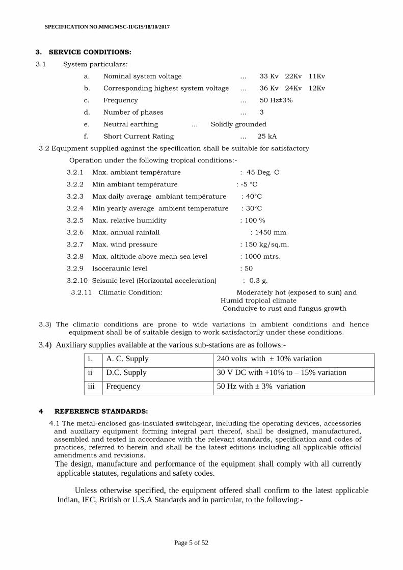
3. SERVICE CONDITIONS:
3.1 System particulars:
a. Nominal system voltage ... 33 Kv 22Kv 11Kv
b. Corresponding highest system voltage ... 36 Kv 24Kv 12Kv
c. Frequency ... 50 Hz±3%
d. Number of phases ... 3
e. Neutral earthing ... Solidly grounded
f. Short Current Rating ... 25 kA
3.2 Equipment supplied against the specification shall be suitable for satisfactory
Operation under the following tropical conditions:-
3.2.1 Max. ambiant température : 45 Deg. C
3.2.2 Min ambiant température : -5 °C
3.2.3 Max daily average ambiant température : 40°C
3.2.4 Min yearly average ambient temperature : 30°C
3.2.5 Max. relative humidity : 100 %
3.2.6 Max. annual rainfall : 1450 mm
3.2.7 Max. wind pressure : 150 kg/sq.m.
3.2.8 Max. altitude above mean sea level : 1000 mtrs.
3.2.9 Isoceraunic level : 50
3.2.10 Seismic level (Horizontal acceleration) : 0.3 g.
3.2.11 Climatic Condition: Moderately hot (exposed to sun) and
Humid tropical climate
Conducive to rust and fungus growth
3.3) The climatic conditions are prone to wide variations in ambient conditions and hence equipment shall be of suitable design to work satisfactorily under these conditions.
3.4) Auxiliary supplies available at the various sub-stations are as follows:-
i. A. C. Supply 240 volts with ± 10% variation
ii D.C. Supply 30 V DC with +10% to – 15% variation
iii Frequency 50 Hz with ± 3% variation
4 REFERENCE STANDARDS:
4.1 The metal-enclosed gas-insulated switchgear, including the operating devices, accessories and auxiliary equipment forming integral part thereof, shall be designed, manufactured,
assembled and tested in accordance with the relevant standards, specification and codes of
practices, referred to herein and shall be the latest editions including all applicable official
amendments and revisions.
The design, manufacture and performance of the equipment shall comply with all currently
applicable statutes, regulations and safety codes.
Unless otherwise specified, the equipment offered shall confirm to the latest applicable
Indian, IEC, British or U.S.A Standards and in particular, to the following:-
SPECIFICATION NO.MMC/MSC-II/GIS/18/10/2017
Page 6 of 52
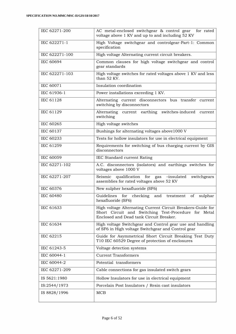
IEC 62271-200 AC metal-enclosed switchgear & control gear for rated
voltage above 1 KV and up to and including 52 KV
IEC 622271-1 High Voltage switchgear and controlgear-Part-1: Common
specification
IEC 622271-100 High voltage Alternating current circuit breakers.
IEC 60694 Common clauses for high voltage switchgear and control
gear standards
IEC 622271-103 High voltage switches for rated voltages above 1 KV and less than 52 KV.
IEC 60071 Insulation coordination
IEC 61936-1 Power installations exceeding 1 KV.
IEC 61128 Alternating current disconnectors bus transfer current
switching by disconnectors
IEC 61129 Alternating current earthing switches-induced current
switching
IEC 60265 High voltage switches
IEC 60137 Bushings for alternating voltages above1000 V
IEC 60233 Tests for hollow insulators for use in electrical equipment
IEC 61259 Requirements for switching of bus charging current by GIS
disconnectors
IEC 60059 IEC Standard current Rating
IEC 62271-102 A.C. disconnectors (isolators) and earthings switches for
voltages above 1000 V
IEC 62271-207 Seismic qualification for gas –insulated switchgears assemblies for rated voltages above 52 KV
IEC 60376 New sulpher hexafluoride (SF6)
IEC 60480 Guidelines for checking and treatment of sulphar
hexafluoride (SF6)
IEC 61633 High voltage Alternating Current Circuit Breakers-Guide for
Short Circuit and Switching Test-Procedure for Metal
Enclosed and Dead tank Circuit Breaker.
IEC 61634 High voltage Switchgear and Control gear use and handling
of SF6 in High voltage Switchgear and Control gear
IEC 62215 Guide for Asymmetrical Short Circuit Breaking Test Duty T10 IEC 60529 Degree of protection of enclosures
IEC 61243-5 Voltage detection systems
IEC 60044-1 Current Transformers
IEC 60044-2 Potential transformers
IEC 62271-209 Cable connections for gas insulated switch gears
IS 5621:1980 Hollow Insulators for use in electrical equipment
IS:2544/1973 Porcelain Post Insulators / Resin cast insulators
IS 8828/1996 MCB
SPECIFICATION NO.MMC/MSC-II/GIS/18/10/2017
Page 7 of 52
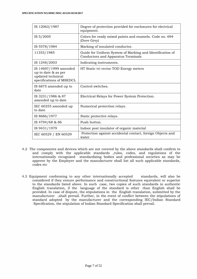
IS 12063/1987 Degree of protection provided for enclosures for electrical
equipment.
IS 5/2005 Colors for ready mixed paints and enamels. Code no. 694
(Dove Grey)
IS 5578/1984 Marking of insulated conductor.
11353/1985 Guide for Uniform System of Marking and Identification of
Conductors and Apparatus Terminals
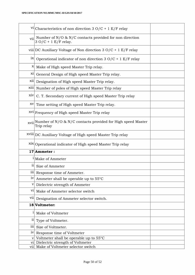
IS 1248/2003 Indicating instruments.
IS 14697/1999 amended up to date & as per
updated technical
specifications of MSEDCL
HT Static tri vector TOD Energy meters
IS 6875 amended up to
date
Control switches.
IS 3231/1986 & 87
amended up to date
Electrical Relays for Power System Protection.
IEC 60255 amended up to date
Numerical protection relays.
IS 8686/1977 Static protective relays.
IS 4794/68 & 86 Push button.
IS 9431/1979 Indoor post insulator of organic material
IEC 60529 / EN 60529 Protection against accidental contact, foreign Objects and
water
4.2 The components and devices which are not covered by the above standards shall confirm to
and comply with the applicable standards ,rules, codes, and regulations of the internationally recognized standardizing bodies and professional societies as may be
approve by the Employer and the manufacturer shall list all such applicable standards,
codes etc
4.3 Equipment conforming to any other internationally accepted standards, will also be
considered if they ensure performance and constructional features equivalent or superior to the standards listed above. In such case, two copies of such standards in authentic
English translation, if the language of the standard is other than English shall be
provided. In case of dispute, the stipulations in the English translation, submitted by the
manufacturer ,shall prevail. Further, in the event of conflict between the stipulations of
standard adopted by the manufacturer and the corresponding IEC/Indian Standard Specification, the stipulation of Indian Standard Specification shall prevail.
SPECIFICATION NO.MMC/MSC-II/GIS/18/10/2017
Page 8 of 52
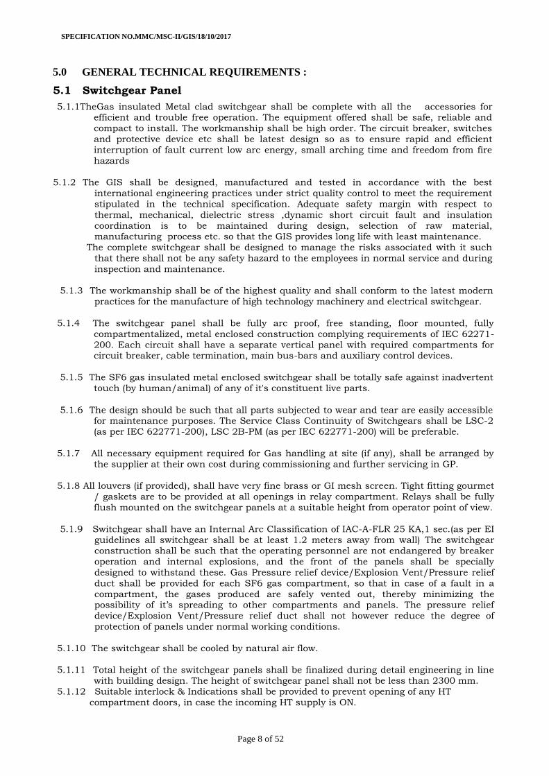
5.0 GENERAL TECHNICAL REQUIREMENTS :
5.1 Switchgear Panel
5.1.1TheGas insulated Metal clad switchgear shall be complete with all the accessories for efficient and trouble free operation. The equipment offered shall be safe, reliable and
compact to install. The workmanship shall be high order. The circuit breaker, switches
and protective device etc shall be latest design so as to ensure rapid and efficient
interruption of fault current low arc energy, small arching time and freedom from fire
hazards
5.1.2 The GIS shall be designed, manufactured and tested in accordance with the best
international engineering practices under strict quality control to meet the requirement
stipulated in the technical specification. Adequate safety margin with respect to
thermal, mechanical, dielectric stress ,dynamic short circuit fault and insulation
coordination is to be maintained during design, selection of raw material, manufacturing process etc. so that the GIS provides long life with least maintenance.
The complete switchgear shall be designed to manage the risks associated with it such
that there shall not be any safety hazard to the employees in normal service and during
inspection and maintenance.
5.1.3 The workmanship shall be of the highest quality and shall conform to the latest modern
practices for the manufacture of high technology machinery and electrical switchgear.
5.1.4 The switchgear panel shall be fully arc proof, free standing, floor mounted, fully
compartmentalized, metal enclosed construction complying requirements of IEC 62271-
200. Each circuit shall have a separate vertical panel with required compartments for circuit breaker, cable termination, main bus-bars and auxiliary control devices.
5.1.5 The SF6 gas insulated metal enclosed switchgear shall be totally safe against inadvertent
touch (by human/animal) of any of it's constituent live parts.
5.1.6 The design should be such that all parts subjected to wear and tear are easily accessible for maintenance purposes. The Service Class Continuity of Switchgears shall be LSC-2
(as per IEC 622771-200), LSC 2B-PM (as per IEC 622771-200) will be preferable.
5.1.7 All necessary equipment required for Gas handling at site (if any), shall be arranged by
the supplier at their own cost during commissioning and further servicing in GP.
5.1.8 All louvers (if provided), shall have very fine brass or GI mesh screen. Tight fitting gourmet
/ gaskets are to be provided at all openings in relay compartment. Relays shall be fully
flush mounted on the switchgear panels at a suitable height from operator point of view.
5.1.9 Switchgear shall have an Internal Arc Classification of IAC-A-FLR 25 KA,1 sec.(as per EI guidelines all switchgear shall be at least 1.2 meters away from wall) The switchgear
construction shall be such that the operating personnel are not endangered by breaker
operation and internal explosions, and the front of the panels shall be specially
designed to withstand these. Gas Pressure relief device/Explosion Vent/Pressure relief
duct shall be provided for each SF6 gas compartment, so that in case of a fault in a
compartment, the gases produced are safely vented out, thereby minimizing the possibility of it’s spreading to other compartments and panels. The pressure relief
device/Explosion Vent/Pressure relief duct shall not however reduce the degree of
protection of panels under normal working conditions.
5.1.10 The switchgear shall be cooled by natural air flow.
5.1.11 Total height of the switchgear panels shall be finalized during detail engineering in line
with building design. The height of switchgear panel shall not be less than 2300 mm.
5.1.12 Suitable interlock & Indications shall be provided to prevent opening of any HT
compartment doors, in case the incoming HT supply is ON.
SPECIFICATION NO.MMC/MSC-II/GIS/18/10/2017
Page 9 of 52
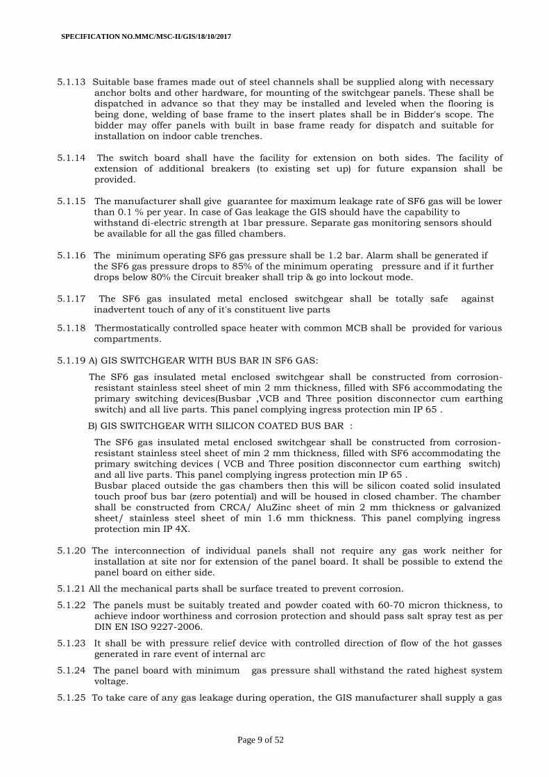
5.1.13 Suitable base frames made out of steel channels shall be supplied along with necessary
anchor bolts and other hardware, for mounting of the switchgear panels. These shall be dispatched in advance so that they may be installed and leveled when the flooring is
being done, welding of base frame to the insert plates shall be in Bidder's scope. The
bidder may offer panels with built in base frame ready for dispatch and suitable for
installation on indoor cable trenches.
5.1.14 The switch board shall have the facility for extension on both sides. The facility of extension of additional breakers (to existing set up) for future expansion shall be
provided.
5.1.15 The manufacturer shall give guarantee for maximum leakage rate of SF6 gas will be lower
than 0.1 % per year. In case of Gas leakage the GIS should have the capability to withstand di-electric strength at 1bar pressure. Separate gas monitoring sensors should
be available for all the gas filled chambers.
5.1.16 The minimum operating SF6 gas pressure shall be 1.2 bar. Alarm shall be generated if
the SF6 gas pressure drops to 85% of the minimum operating pressure and if it further
drops below 80% the Circuit breaker shall trip & go into lockout mode.
5.1.17 The SF6 gas insulated metal enclosed switchgear shall be totally safe against
inadvertent touch of any of it's constituent live parts
5.1.18 Thermostatically controlled space heater with common MCB shall be provided for various
compartments.
5.1.19 A) GIS SWITCHGEAR WITH BUS BAR IN SF6 GAS:
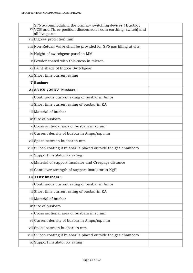
The SF6 gas insulated metal enclosed switchgear shall be constructed from corrosion-resistant stainless steel sheet of min 2 mm thickness, filled with SF6 accommodating the
primary switching devices(Busbar ,VCB and Three position disconnector cum earthing
switch) and all live parts. This panel complying ingress protection min IP 65 .
B) GIS SWITCHGEAR WITH SILICON COATED BUS BAR :
The SF6 gas insulated metal enclosed switchgear shall be constructed from corrosion-
resistant stainless steel sheet of min 2 mm thickness, filled with SF6 accommodating the primary switching devices ( VCB and Three position disconnector cum earthing switch)
and all live parts. This panel complying ingress protection min IP 65 .
Busbar placed outside the gas chambers then this will be silicon coated solid insulated
touch proof bus bar (zero potential) and will be housed in closed chamber. The chamber
shall be constructed from CRCA/ AluZinc sheet of min 2 mm thickness or galvanized sheet/ stainless steel sheet of min 1.6 mm thickness. This panel complying ingress
protection min IP 4X.
5.1.20 The interconnection of individual panels shall not require any gas work neither for
installation at site nor for extension of the panel board. It shall be possible to extend the
panel board on either side.
5.1.21 All the mechanical parts shall be surface treated to prevent corrosion.
5.1.22 The panels must be suitably treated and powder coated with 60-70 micron thickness, to
achieve indoor worthiness and corrosion protection and should pass salt spray test as per
DIN EN ISO 9227-2006.
5.1.23 It shall be with pressure relief device with controlled direction of flow of the hot gasses generated in rare event of internal arc
5.1.24 The panel board with minimum gas pressure shall withstand the rated highest system
voltage.
5.1.25 To take care of any gas leakage during operation, the GIS manufacturer shall supply a gas
SPECIFICATION NO.MMC/MSC-II/GIS/18/10/2017
Page 10 of 52
refilling kit comprising gas cylinder, manometer, reduction valve adopter, pressure
measuring device, connecting and filling hose, etc shall be also be supplied under the
scope of work.
5.1.26 Temperature compensated gas density monitor shall be provided on the front side to
monitor SF6 gas and for interlock purpose.
5.1.27 No any special tools shall be required for installing the equipment.
5.1.28 The design of the panel should be such that no permanent or harmful distortion occurs
either when being lifted by eyebolts or when moved into position by rollers.
5.1.29 Paint shade of Indoor Switchgear shall be 694 as per IS:5(Dove Grey).
5.1.30 SF6 gas pressure and density should maintained as per relevant IS and IEC, if gas
pressure or density goes below specified limits, breaker should go in lockout mode. Non-
Return Valve shall be provided for SF6 gas filling at site.
5.2 11KV INDOOR AIS SWITCHGEAR PANEL
Switchgear for Indoor installation shall be metal clad, draw-out type and fully compartmentalized having 25 kA short time current rating. All panels shall be of unitized
construction providing facility for extensions on both sides. Three types of switchgear
panels are required, viz. the incomer panel, the bus section panel and the feeder
(outgoing) panel. Circuit Breakers used shall be VCBs of specified rating for the various
types. The design of the breaker truck shall be such that there will be flexibility of
interchanging between incomer, bus-section and feeder trucks, where similar rated breakers are offered. These panels shall be constructed from CRCA/ AluZinc sheet of min
2 mm thickness or galvanized sheet/ stainless steel sheet of min 1.6 mm thickness.
These panels complying ingress protection min IP 4X.
6. Busbar and Insulators
6.1 33KV, 22 KV busbar
33 Kv, 22 KVbusbar can be housed in SF6 gas chamber or outside the gas chambers. If
placed outside the gas chambers then this will be silicon coated solid insulated touch
proof bus bar and will be housed in closed chamber. 33 KV and 22 Kv bus bars shall be made of electrolytic copper and shall be rated for 1250
Amps continuous current, Cross sectional area shall not be less than 785 sq.mm. and bus bar size calculation / supporting type test report shall be submitted for approval.
Current density of copper shall not exceed more than 1.6Amps/sq. mm. Bus bar cross-
section shall be uniform throughout the length of switchgear panel. The bus bar
edges/ends shall be rounded off/chamfered so that there will not be any sharp
edges/projections.
6.2 11KV busbar.
6.2.1 11KV bus bar can be housed in SF6 gas chamber or outside the gas chambers. If placed
outside the gas chambers then this will be silicon coated solid insulated touch proof bus
bar and will be housed in closed chamber. 11 kV bus bars shall be made of electrolytic copper and shall be rated for 800 Amps
continuous current. Cross sectional area shall not be less than 500 sq.mm. and bus bar
size calculation / supporting type test report shall be submitted for approval. Current
density of copper shall not exceed more than 1.6Amps/sq. mm. Bus bar cross-section
shall be uniform throughout the length of switchgear panel. The bus bar edges/ends shall be rounded off/chamfered so that there will not be any sharp edges/projections
6.2.1 11 KV Busbar can be housed in air insulated closed chamber. The bus bar edges/ends
shall be rounded off/chamfered so that there will not be any sharp edges/projections.
11 kV bus support insulators and other equipment insulators shall have a minimum
creepage distance of 127 mm. These insulators shall be of solid core porcelain or epoxy resin cast, with suitable petticoat design. Insulators shall have a cantilever strength of
SPECIFICATION NO.MMC/MSC-II/GIS/18/10/2017
Page 11 of 52
not less than 1200 KgF. All fasteners (Nuts Bolts) used for bus bar connections shall be
of non magnetic stainless steel. Only belleville type washers shall be provided for each
nut bolt. If the fasteners used are not of stainless steel the tenderer shall state in their offer the material used and confirm that the same is non-magnetic and is superior to
stainless steel. The bus bars along with their supporting insulators etc. shall have a short
time current rating of 25 KA for 3 sec. This shall be confirmed by the manufacturers in
their technical offer.
6.3 Busbar shall be of made of electrolytic high grade Copper of adequate size and bus bar
size calculation / supporting type test report shall be submitted for approval (current density of copper shall not exceeded more than 1.6 Amp/sq.mm). They shall be
adequately supported on insulators to withstand electrical and mechanical stresses due
to specified short circuit currents.
6.4 Busbar shall be supported on the insulators such that the conductor expansion and
contraction are allowed without straining the insulators and should withstand electrical and mechanical stresses due to specified short circuit currents. (IS)
6.6 All piping for SF6 gas shall be made of copper & their fittings shall be made of non-
magnetic stainless steel.
6.7 Busbar insulators shall be of arc and track resistant, high strength, non-hygroscopic, non-combustible type and shall be suitable to withstand stresses due to over-voltages,
and short circuit current. In case of organic insulator partial discharge shall be limited to
50 pico coulomb at rated Voltage X 1.1/√3 as per IS 3156
6.8 All busbars shall have suitable phase identification. Bus switching scheme shall be as per
Single Line diagram attached with bidding documents.
6.9 The temperature of the busbars and all other equipment, when carrying the rated current
continuously shall be limited 60deg C above ambient temperature 45deg C as per the
relevant Standards
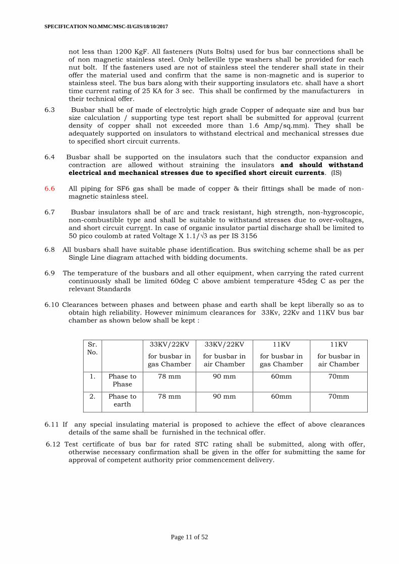
6.10 Clearances between phases and between phase and earth shall be kept liberally so as to
obtain high reliability. However minimum clearances for 33Kv, 22Kv and 11KV bus bar chamber as shown below shall be kept :
Sr.
No.
33KV/22KV
for busbar in
gas Chamber
33KV/22KV
for busbar in
air Chamber
11KV
for busbar in
gas Chamber
11KV
for busbar in
air Chamber
1. Phase to Phase
78 mm 90 mm 60mm 70mm
2. Phase to
earth
78 mm 90 mm 60mm 70mm
6.11 If any special insulating material is proposed to achieve the effect of above clearances
details of the same shall be furnished in the technical offer.
6.12 Test certificate of bus bar for rated STC rating shall be submitted, along with offer, otherwise necessary confirmation shall be given in the offer for submitting the same for
approval of competent authority prior commencement delivery.
SPECIFICATION NO.MMC/MSC-II/GIS/18/10/2017
Page 12 of 52
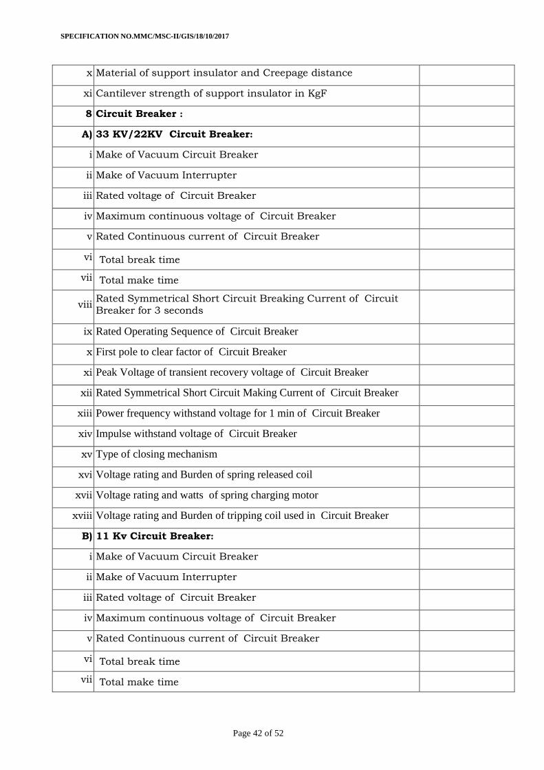
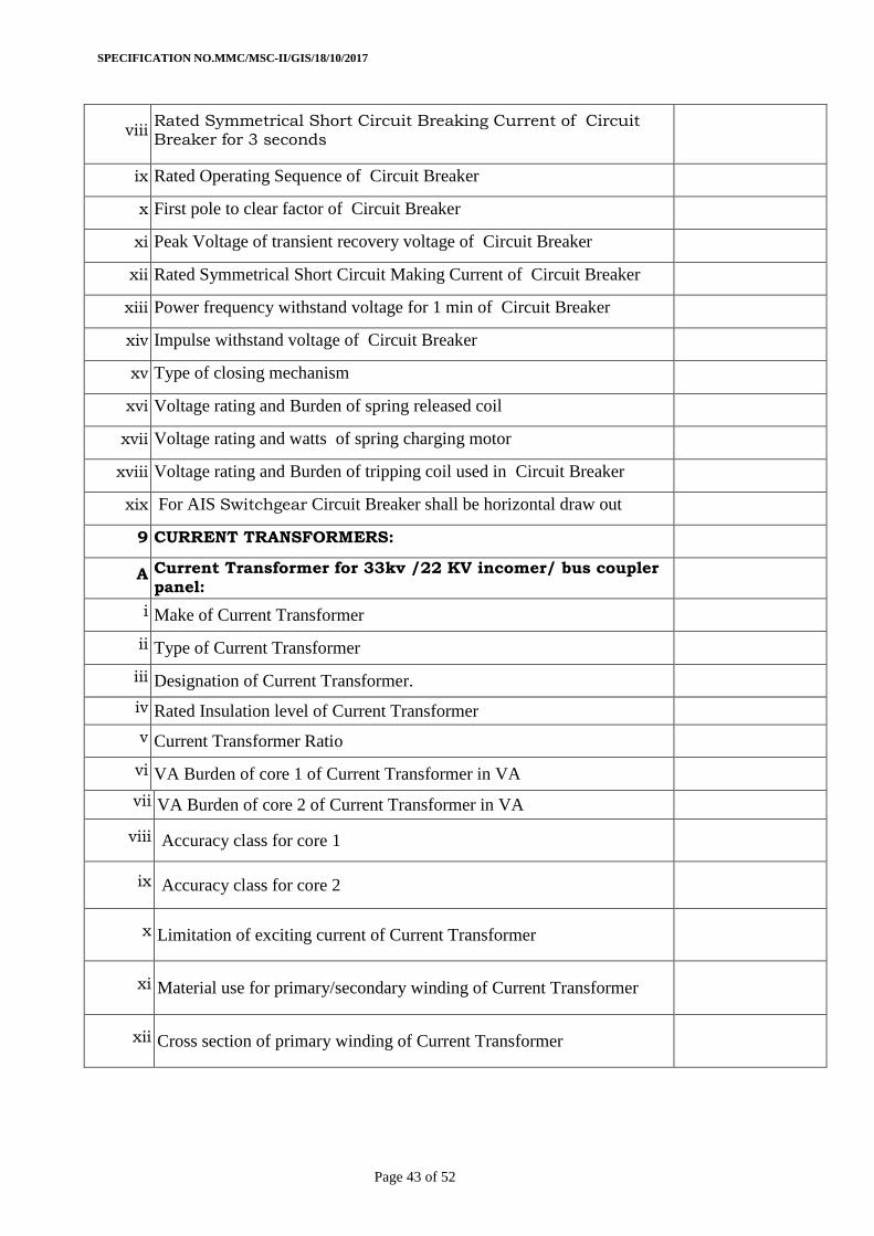
7.0 Circuit Breaker
7.1 Vacuum circuit breaker shall be used for 33 KV, 22 KV GIS (Gas Insulated Switchgear) and Vacuum Circuit Breaker can be used for 11KV GIS or 11 KV AIS (Air Insulated Switchgear).
For GIS:- 33 KV, 22 KV or 11 KV Vacuum circuit breaker shall comprise of three single pole
interrupting units or 3-pole interrupting unit, operated through a common shaft by a
sturdy operating mechanism.
For AIS :- 11KV Vacuum Circuit Breaker shall be horizontal draw out , Horizontal Isolation type. Breakers shall be of 3 pole design for use in 11 kV indoor switchgear.
7.2 Circuit breaker shall be re-strike free, stored energy operated and trip free type. Motor
wound closing spring charging shall only be acceptable. Anti-pumping features shall be
provided for each breaker. An arrangement of two breakers in parallel to meet a specified
current rating shall not be acceptable. (No parallel interrupter).
7.3 Circuit breaker shall be provided with two trip coils.
7.4 Suitable indicators shall be provided on the front of panel to indicate OPEN / CLOSED
conditions of the circuit breaker, and CHARGED / DISCHARGED conditions of the
closing spring, SF6 gas density monitor for all gas compartments.
7.5 The rated control supply voltage shall be as mentioned elsewhere under Technical parameters. The closing coil shall operate satisfactorily at all values of control supply
voltage between 80-110% of the rated voltage. The trip coil shall operate satisfactorily
under all operating conditions of the circuit breaker up to its rated short circuit breaking
current at all values of control supply voltage between 70-110% of the rated voltage. The
trip coil shall be so designed that it does not get energized when its healthiness is monitored by indicating lamps and trip coil supervision relay.
7.6 The time taken for charging of closing spring shall not exceed 30 seconds. The spring
charging shall take place automatically preferably after a closing operation. Breaker
operation shall be independent of the spring charging motor which shall only charge the
closing spring. Opening spring shall get charged automatically during closing operation. As long as power supply is available to the charging motor, a continuous sequence of
closing and opening operations (CO) shall be possible. Spring charging motors shall be
capable of starting and charging the closing spring twice in quick succession without
exceeding acceptable winding temperature when the supply voltage is anywhere between
80-110% of rated voltage. The initial temperature shall be as prevalent in the switchgear panel during full load operation with 55 deg. C ambient air temperature. The motor shall
be provided with over load protection.
7.7 Motor windings shall be provided with class E insulation or better. The insulation shall be
given tropical and fungicidal treatment for successful operation of the motor in a hot,
humid and tropical climate.
7.8 For 33kv, 22kv & 11kv incomer :
Tripping time : 60-70 ms (Including Relay Time) Closing Time < 80 ms.
For 11kv feeder :Tripping time:45-50 ms (Including Relay Time) Closing Time: 40-60 ms.
7.9 Manual Spring Charging shall be provided. All the basic mechanical ON/OFF of Circuit
breaker, Disconnector& earth switch operation, manual spring charge of Circuit Breaker
must be possible without opening the door to ensure the operator safety.
7.10 Breaker operations (Mechanical Endurance) as per relevant IS/IEC Amended up to date.
7.11 The circuit-breaker has to control at least 10,000 Make-Break cycles without maintenance.
The mechanical life and operating cycles of the vacuum interrupter shall confirm relevant
IS/IEC amended up to date.
SPECIFICATION NO.MMC/MSC-II/GIS/18/10/2017
Page 13 of 52
7.12 Tripping coil, closing coil and motor mechanism shall be easily accessible for maintenance
purpose.
7.13 The circuit breaker shall be provided with motor operated spring charged closing. Spring
charging motor shall be suitable for 240V, 50 Hz, single phase AC. Suitable rating starter
shall be provided for Motor protection. Spring release coil for closing shall be suitable for
30V DC.
7.14 Tripping of the circuit breakers shall be through "Shunt trip" coils rated for 30V DC auxiliary
supply. It shall be possible to trip the breaker manually in case of necessity.
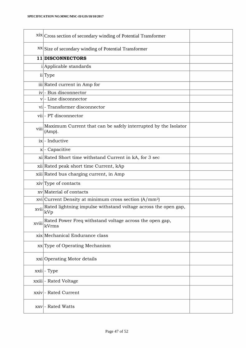
8 Disconnector and earthing switch:
8.1 Each Switchgear panel shall be provided with three (3) position disconnecting-cum-earthing
switch of required rating.
8.2 It shall be possible to control these switches from front of the panel & remotely from
SCADA/SAS through IED.
8.3 Necessary indication shall be provided on the front of the panel for Close/Open status of the
three position switches.
8.4 The safe, positive and foolproof interlocks shall be provided for personnel safety and equipment safety.
8.5 Key interlocks shall be provided for local manual operations.
8.6 Mechanical interlocks shall be provided for following conditions Three position disconnector
cum earth switch cannot be operated when circuit breaker is closed.
8.7 The operating handle /lever cannot be removed until the switching operation has been
completed.
8.8 Earthing shall be additionally secured against” de-earthing” by providing a padlock.
8.9 The cable compartment cover can only be opened if the panel is earthed.
8.10 In addition to above, relevant all electrical interlocks shall also be provide.
8.11 Disconnecting switches shall be motor operated where SCADA is implemented)Isolators or
isolators combined with earthing switches (3 position switches) shall be motor operated. In
cases of emergency, manual operation must be possible.
8.12 The earthing position for all 3 phases must be visible via a mechanical position indicator
(MIMIC) directly connected to the drive shaft on panel front Fascia. The mechanical operation
of isolator / 3 position disconnector switch must be possible with door closed for operator
safety.
8.13 The large view ports to be provided to make it easy to visually check the switching position
and to ensure safety of operations thereof.
9 ) Control and Interlocks
9.1 The circuit breaker shall normally be controlled remotely from SAS/SCADA system through
closing and trip coils. However, it shall also be designed to control locally from Indoor
Switchgear panel. Suitable mimic on Panel shall be provided.
9.2 Facilities shall be provided for mechanical tripping of the breaker in an emergency. Facility
shall also be provided for manual charging of the stored energy mechanism for a
complete duty cycle.
SPECIFICATION NO.MMC/MSC-II/GIS/18/10/2017
Page 14 of 52
9.3 Necessary mechanical & Electrical interlocks shall be provided between CB, Isolator &
Earth switches for safe operation.
9.4 Each CB, Isolator & earth switch shall have 8 NO + 6 NC Auxiliary spare of good quality
(corrosion free and easy for making connection) for future use by owner. It should be
located at accessible position in panel.
9.5 All the binary inputs/outputs shall be wired to the terminals & kept ready for future
SCADA connectivity.
10 Earthing and Earthing Devices
10.1 The grounding system for GIS shall be designed and provided as per IEEE-80-2000 and
CIGRE- 44to protect operating staff against any hazardous touch voltages and electro-magnetic interferences.
10.2 The earth busbar made of electrolytic high grade copper with cross sectional area of
minimum 240 sq mm shall be provided at the bottom in all the panels and interconnected
with adjacent panels in the panel board through a connecting link to form a common
earth busbar for the entire panel board ready to connect to the substation earthing grid. It
shall be welded to the framework of each panel and each breaker earthing contact bar. The earth bus shall have sufficient cross section (minimum 240 sq mm) to carry the
momentary short-circuit and short time fault currents to earth without exceeding the
allowable temperature rise.
10.3 Suitable arrangement shall be provided at each end of the earth bus for bolting to station earthing grid. All joint splices to the earth bus shall be made through at least two bolts
and taps by proper lug and bolt connection.
10.4 All non-current carrying metal work of the switchboard shall be effectively bonded to the
earth bus. Electrical continuity of the whole switchgear enclosure frame work and the
truck shall be maintained even after painting.
10.5 All metallic cases of relays, instruments and other panel mounted equipment shall be
connected to earth by independent stranded copper wires of size not less than 2.5 sq.
mm. Insulation colour code of earthing wires shall be green. Earthing wires shall be
connected to terminals with suitable clamp connectors and soldering shall not be acceptable. Looping of earth connections which would result in loss of earth connection to
other devices, when a device is removed is not acceptable. However, looping of earth
connections between equipment to provide alternative paths of earth bus is acceptable.
10.6 PT and CT secondary neutral point earthing shall be at one place only on the terminal
block. Such earthing shall be made through links so that earthing of one secondary circuit may be removed without disturbing the earthing of other circuits.
10.7 The panel shall have Voltage Presence Indicator (VPI) to warn the operator against
earthing of live connections.
10.8 All hinged doors shall be earthed through flexible earthing braid.
10.9 Separate earthing for switchgear and C&R panel shall be provided.
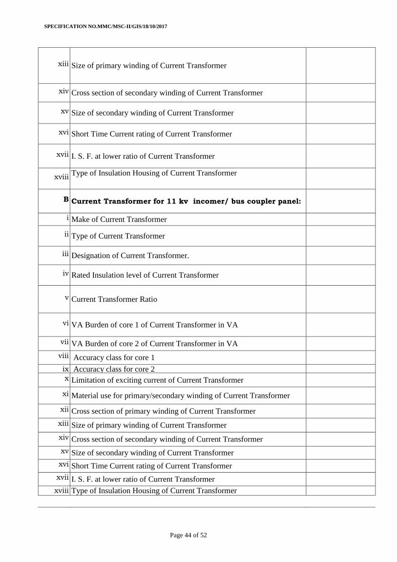
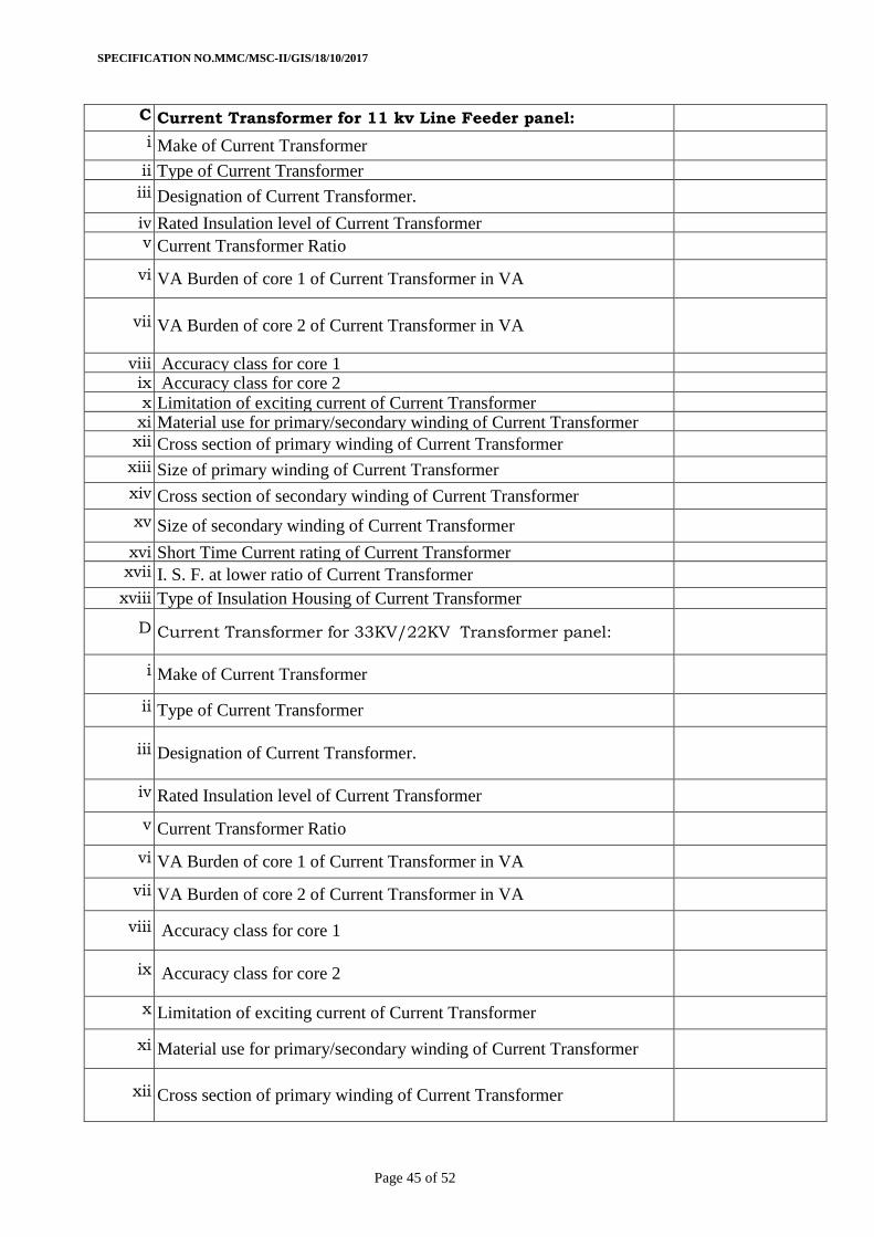
11.0 CURRENT TRANSFORMERS:
11.1 The C.Ts. being prone to failure due to various reasons, the quality and reliability of the CTs
are of vital importance. C.T. shall be rated for 25 kA for 3 sec. short time current.
Insulation used shall be of very high quality, details of which shall be furnished in the
technical offer.
SPECIFICATION NO.MMC/MSC-II/GIS/18/10/2017
Page 15 of 52
11.2 The instrument security factor for metering core shall be low enough but not greater than 5
at lower ratio. This shall be demonstrated on metering core in accordance with the
procedure specified in relevant IS/IEC.
11.3 Primaries shall be wound or bar type, rigid, high conductivity grade copper conductor.
Unavoidable joints on the primary conductor shall be welded type, preferably lap type. The
current density at any point shall not exceed 1.6 A/sq. mm.
11.4 Suitable insulated copper wire of electrolytic grade shall be used for CT secondary
winding. Multi ratio in CT shall be achieved by reconnection of secondary winding tapping.
11.5 Secondary terminal studs shall be provided with at least three nuts, two plain and two
spring washers for fixing leads. The stud, nut and washer shall be of brass, duly nickel
plated. The minimum outside diameter of the studs shall be 6 mm. The length of at least 15
mm shall be available on the studs for inserting the leads. The space clearance between nuts
on adjacent studs when fitted shall be at least 10 mm.
11.6 The CTs shall be resin/epoxy cast. Contact tips on primary terminals shall be silver plated.
Correct polarity shall be invariably marked on each primary and secondary terminal.
11 7 All current transformers for GIS shall be ring type (Tape wound / resin cast) .
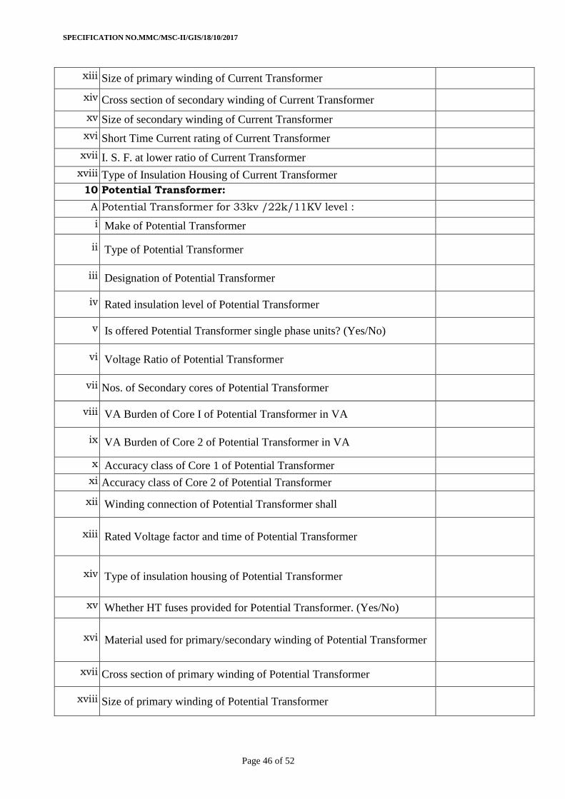
12.0 POTENTIAL TRANSFORMER
12.1 Potential transformers shall be single phase units connected to the line side in the respective
incomer. H.V side shall be connected in star formation and L.V. side in star/open delta
formation.
12.2 PT may be provided in a separate compartment. The primary and secondary contacts
(moving & fixed type) shall have firm grip while in service. Service position locking
mechanism shall be provided and indicated by bidder in relevant drawing. Rigidity of
primary stud point with earth bus in service position shall be confirmed.
12.3 P.T. shall be epoxy/resign cast. Contact tips of primary/secondary contacts shall be silver
plated. Correct polarity shall be distinctly marked on primary and secondary terminal.
12.4 Secondary terminal studs shall be provided with at least three nuts, two plain and two
spring washers for fixing leads. The stud, nut and washer shall be of brass, duly nickel
plated. The minimum outside diameter of the studs shall be 6 mm. The length of at least 15
mm shall be available on the studs for inserting the leads. The space clearance between nuts
on adjacent studs when fitted shall be at least 10 mm.
12.5 Each secondary core will be protected by suitable MCB.
12.6 In case of 2 Power Transformers are in parallel, 2nd
core of PTs shall be used for
directional protection.
Note : Instrument transformers shall be suitable for continuous operation at the ambient
temperature prevailing inside the switchgear enclosure, when the switchboard is
operating at its rated load and the outside ambient temperature is 55 deg. C. The class of insulation shall be E or better.
All instrument transformers shall withstand the power frequency and impulse test
voltage specified for the switchgear assembly. The current transformer shall further
have the dynamic and short time ratings at least equal to those specified for the
associated switchgear and shall safely withstand the thermal and mechanical stress
SPECIFICATION NO.MMC/MSC-II/GIS/18/10/2017
Page 16 of 52
produced by maximum fault currents specified when mounted inside the switchgear for
circuit breaker modules.
The parameters of instrument transformers specified in this specification are indicative and shall be finalized by the Employer during detailed engineering, considering the
actual burden of various relays and other devices finally selected. In case the Bidder
finds that the specified ratings are not adequate for the relays and other devices offered
by him, he shall offer instrument transformer of adequate ratings without any cost
implication.
All instrument transformers shall have clear indelible polarity markings. All secondary terminals shall be wired to separate terminals on an accessible terminal block.
13 POWER CABLE TERMINATION
13.1 Cable termination compartment shall receive the stranded Aluminum conductor, XLPE insulated, shielded, armored, PVC jacketed, single core / three core, unearthed / earthed
grade HT power cable(s) as specified in Section -Project.
13.2 Adequate clearance shall be kept between the cable lug bottom ends and gland plates for
stress cone formation for XLPE cables. Inter-phase clearance in the cable termination
compartment shall be adequate to meet electrical and mechanical requirement besides
facilitating easy connections and disconnection of cables. Dimensional drawing of cable
connection compartment showing the location of lug, glands, gland plates etc. and the electrical clearances available shall be submitted during detail engineering.
13.3 Cable termination compartment shall have provision for termination of power cables of
sizes indicated in the bidding documents. Cable entry shall generally be from the bottom;
however, this shall be finalized during detail engineering.
13.4 Necessary cable termination plugs shall be part of Indoor switchgear panel supplier for all
panels. Scope also includes Panel terminal ends jointing/connection with HT cables.
13.5 Bushings and arc-resistant cable covers/cable boot shall be provided in cable compartment to receive /connect 2 no’s of 3X300 sq.mm Aluminum XLPE Power Cable for outgoing
feeders and 3 no’s of 3X 300 sq.mm Aluminum XLPE power cable for incoming feeders or
as per requirement.
13.6 Indoor cable terminations kits to connect the above mentioned cables to the panel cable
connections shall be in the scope of the tender.
13.7 For 33KV, 22 KV end termination required for XLPE cable should be plug in type touch proof type for eg. Pfisterer, Euromould, Tyco etc
13.8 On 11KV side the end cable termination required will be conventional heat shrinkable
14 Low voltage Compartment (Instrument Chamber)
14.1 The panels shall be with low voltage compartment consisting control switches, indication
and metering instruments, protection relays and other secondary equipment’s. The dynamic mimic shall be provided on the front fascia and not on the LV chamber.
14.2 The front side shall have Mimic as per single line diagram with control switches and
mechanical and electrical ‘Position indicators’ circuit breakers, disconnectors and earth switch
14.3 Control switches/Pushbuttons shall be provided adjacent to respective equipment
position indicators in Mimic for ON-OFF operation of circuit breakers, disconnectors and
earth switches.
14.4 The SCADA compatible Trivector Meters (TVM) shall be provided and to be integrated with
substation Automatic System(either RS232 or RS 485)
14.5 Live line Indicators :- Capacitive voltage indicators shall be provided on feeder side in
outgoing feeders, on bus side & feeder side in incoming feeders and on both the sides in
Bus coupler to indicate the voltage presence in each phase and to prevent the closing of
SPECIFICATION NO.MMC/MSC-II/GIS/18/10/2017
Page 17 of 52
earth switch in case the part is live. It shall have sufficient output contacts for substation
Automation System and interlock purpose.
14.6 Panel interlocking wiring cables shall be supplied with panels.
15.0 SCADA Compatibility
The panels shall be fully SCADA compatible
16.0 Numerical Protection Relays (IEDs)
Indoor switchgear panels shall have communicable numerical protection relays (IEDs) complying with IEC-61850on all feeders which shall be networked on Ethernet to
communicate with substation SAS/SCADA system on IEC-61850.Relay shall have
redundant RJ45 ports complying to PRP redundancy of IEC 61850. These IEDs shall also
be used for control & monitoring the switchgear from SAS. In addition to status of devices
(CBs/Isolators/Earth Switches) and equipment alarms, Metering data shall also be made
available to SAS/SCADA station from protection IEDs. Further, Trivector meters with Modbus / IEC 103 protocol are also envisaged, which will be connected in daisy-chain-
link to communicate to station SAS. Modbus /IEC 103to IEC 61850 converters shall be
provided for integration with SAS.
The Bidder’s scope shall include the followings:
a) Communicable Numerical Protection Relays (with IEC 61850 in each of the feeders
& Bus-section/Bus coupler
b) IED’s / Numerical Relays shall have digital display, display to facilitate settings,
relay operations and to view measurement, event and alarm etc.
c) Cat5e Ethernet cable for connection of Numerical Relays (IEDs) to Ethernet
switches and Optical cable between Ethernet switch (for indoor switch gear IEDs)
and ring/ redundant network of Substation LAN switch shall be used.
d) Required number of Ethernet switches mounted in Indoor Switchgear panels for communication with IEDs on IEC 61850 / protocol.
e) The SAS/SCADA system has been envisaged as part of main substation. Bidder
shall facilitate in successful Integration of Numerical Relays to the SAS/SCADA
system through Ethernet switches.
16.1 All Numerical relays shall be of proven design for the application satisfying requirements
specified elsewhere and shall be subject to Employer's approval. Numerical Relays shall
have appropriate setting ranges, accuracy, resetting ratio, transient overreach and other
characteristics to provide required sensitivity for the intended application.
16.2 All numerical relays shall be rated for control supply voltage as mentioned elsewhere
under system parameters and shall be capable of satisfactory continuous operation
between 80-110% of the rated voltage. Making, carrying and breaking current ratings of
their contacts shall be adequate for the circuits in which they are used. Heavy duty
binary output contacts of IEDs to be used for breaker close and trip commands shall be so rated as to be used directly used in the closing and tripping circuits of breaker without
the need of any interposing / master trip relays.
16.3 Threshold voltage for binary inputs shall be suitably selected to ensure avoidance of mal-
operation due to stray voltages and also to fulfill trip circuit supervision functionality for pre-trip & post-trip.
16.4 All IEDs shall have freely programmable optically isolated binary inputs (Minimum 16BI)
and potential free binary output (Minimum 10 BO) contacts as per scheme configuration.
These I/O points shall be used for wiring of status of devices (CB/Isolator/Earth switch)
and equipment alarms etc.(list & Requirement)
SPECIFICATION NO.MMC/MSC-II/GIS/18/10/2017
Page 18 of 52
16.5 Failure of a control supply and de-energization of a relay shall not initiate any circuit
breaker operation.
16.6 Relays shall have event recording feature with Date &time stamping. Event records &
alarms shall be stored in Non-volatile memory and failure of control supply shall not
result in deletion of any of these data.
Relay shall have disturbance recorder.
16.7 All Numerical relays shall have features for electrical measurements of current.
16.8 Directional numerical relays shall have provision of both current (CT) and voltage (PT)
inputs as required for protection & measurement purposes using protection cores.
16.9 All numerical relays shall have built-in key pad / keys to allow relay setting from relay front. Resetting of relay shall be possible from remote SCADA.
16.10 Relays shall have suitable output contact for circuit breaker failure protection (LBB: Local
Breaker Backup) logic.
16.11 Relays shall have self diagnostic feature on display with continuous self check for power failure, program routines, memory and main CPU failures and a separate output contact
for indication of any failure.
16.12 Contractor shall submit applicable Type Test reports for Numerical relays as per IEC
including report for IEC 61850 protocol from accredited lab.
17 Control & Protection System
All numerical relays shall communicate to station SCADA / SAS on IEC-61850 communication protocol. It is envisaged that these protection IEDs shall be used for CB
control & monitoring of bay equipments. The type test reports along with communication
protocol shall be submitted as per relevant IS/IEC amended up to date.
18 Numerical Transformer Protection Relay
18.1 The relay shall have instantaneous as well as time delayed three over current (50) and
one earth fault (50N) protection elements. with standard inverse characteristics (1.3 and
3 Sec) IDMT.
18.2 The over current element should have the minimum setting adjustable between 20-200% of CT secondary rated current with increment/decrement by 1 % and high set setting
100-2000%.
18.3 The earth fault element of relay shall be suitable for detection of earth fault currents in
the range of 5% to 80% of the CT rated current (IDMT) and high set 100-1000%.
18.4 The relay shall have selectable directional & non-directional feature.
18.5 For transformers of rating 5MVA and above, definite time delayed Stand by earth fault
protection shall be provided having a pick up setting range of 10% to 40% with a timer
delay of 0sec to 3 sec. in step of 0.01 s
18.6 The relay shall allow higher setting during transformer charging (inrush) and lower
setting during normal operating condition.
18.7 Transformer troubles like Buchholz, Winding temperature, Oil temperature & Pressure
Relief Device trips etc. (as applicable) shall be wired independently to separate binary inputs of the relay and shall be configured to issue trip command to the breaker.
Similarly alarm points shall be wired separately to binary inputs of the relay.
SPECIFICATION NO.MMC/MSC-II/GIS/18/10/2017
Page 19 of 52
18.8 Trip circuit supervision shall be provided to monitor the circuit breaker trip circuit both in
pre-trip and post-trip conditions.
19 Numerical Line Protection Relay:
19.1 The relay shall have instantaneous as well as time delayed three over current (50) and
one earth fault (50N) protection elements. with standard inverse characteristics (1.3 and
3 Sec) IDMT.
19.2 The over current element should have the minimum setting adjustable between 20-
200%(in step of 1%)of CT secondary rated current.
19.3 The earth fault element of relay shall be suitable for detection of earth fault currents in the range of 5% to 80% of the CT rated current.
19.4 The relay shall have selectable directional & non-directional feature
19.5 Trip circuit supervision shall be provided to monitor the circuit breaker trip circuit both in
pre-trip and post-trip conditions.
20 Numerical Bus Coupler/Bus-Section Protection Relay:
20.1 The relay shall have instantaneous as well as time delayed three over current (50) and one
earth fault (50N) protection elements.
20.2 The over current element should have the minimum setting adjustable between 20-
200%(in step of 1%) of CT secondary rated current.
20.3 The earth fault element of relay shall be suitable for detection of earth fault currents in
the range of 5% to 80% of the CT rated current.
20.4 No bus volt signal shall be configured in the relay for use in control logics and other
Protections and Control functions in the Relays.
20.5 Trip circuit supervision shall be provided to monitor the circuit breaker trip circuit both in
pre-trip and post-trip conditions.
21 Other Control and Protections features:
21.1 Control of breakers, three position Isolators & Earth switches shall be carried out from
the station HMI of SAS/SCADA system through the LAN and the numerical relays.
21.2 The station HMI shall have a graphical dynamic Plant Key Single Line Diagram to view the
complete system status. This shall include the status of the switchgears, measurement
values, operation counters, graphical alarm representation, etc. Spontaneous changes of a state, typically opening of a circuit breaker from a protection, shall have a specific
colour code. All the Breakers with the status shall be clearly displayed along with values
of currents, voltages, and frequency, active and reactive powers etc.
21.3 Schematics requiring auxiliary relays / timers for protection function shall be part of
numerical relay. Timer functions shall be configurable for on & off delays as per requirement.
21.4 The numerical relay shall be capable of measuring and storing values of a wide range of
quantities, all events, faults and disturbance recordings with a Date & time stamping using the internal real time clock. Battery backup for real time clock in the event of power
supply failure shall be provided.
SPECIFICATION NO.MMC/MSC-II/GIS/18/10/2017
Page 20 of 52
21.5 At least 100 time tagged events / records shall be stored with date & time stamping.
Details of at least 5 previous faults including the type of protection operated, operating
time, all currents & voltages and time of fault.
21.6 Automatic testing, power on diagnostics with continuous monitoring shall be provided in
the IED to ensure high degree of reliability. Test features such as examination of input
quantities, status of digital inputs and relay outputs shall be available on the user
interface
21.7 The alarm/status of each individual protection function and trip operation including
measurement values shall be communicated to the SAS/SCADA system.
21.8 Sequence of events shall have 1ms resolution at device level.
21.9 It shall be possible to carryout open / close operation of breakers from a laptop by
interfacing from the relay front port during initial commissioning.
22 ETHERNET SWITCH:
22.1 Ethernet switches shall be ‘substation hardened‘, and shall comply with IEC61850 for
communications with IEDs. The Ethernet switches shall be of managed type with two (2)
No. of Fiber optic cable ports and at least Sixteen (16) Copper ports to achieve the LAN
configuration. More no. of switches or higher ports switch can also be supplied to meet all IEDs & Multi-function meters requirements for the LAN. The Ethernet switches shall have
features to support the redundant rings. These switches shall be mounted in the
switchgear Panels. The FO ports shall be Single-mode 1000 Mbps ports. Copper ports
shall be 10/100Mbps ports.
22.2 Necessary software for configuration and real-time network monitoring shall be provided
along with the Ethernet switches.
23 GENERAL REQUIREMENTS FOR ERECTION
23.1 Contractor shall move all equipment into the respective rooms through the regular door
or openings specifically provided for this purpose. No parts of structure shall be utilized
to lift or erect any equipment without prior permission of Engineer-in-charge.
23.2 Switchgear shall be installed on finished surfaces, concrete or steel sills. Contractor
shall be required to install and align any channel sills which form part of foundations.
Minor modifications to foundations shall be carried out by the Contractor. Contractor
shall take utmost care in handling instruments, relays and other delicate
mechanisms. Wherever the instruments and relays are supplied loose along with
switchgear, they shall be mounted only after the associated switchgear panels have been erected and aligned. The blocking materials, employed for safe transit of
instrument and relays shall be removed after ensuring that panels have been
completely installed and no further movement of the same would be necessary. Any
damage shall be immediately reported to Engineer.
23.3 Contractor shall include all special tools required for regular operation & routine
maintenance of switchgear.
24 CONTROL WIRING
24.1 All wiring shall be carried out with 1100 volts grade with ISI mark single core,
multistrand flexible tinned copper wires with non flammable, fire resistant PVC insulation. The conductor size shall be 4 sq mm for CT’s and 2.5sq mm (minimum) for
other circuits. Wiring trough may be used for routing the cables. Wire numberings and
colour code for wiring shall be as per IS:5578/1984. The wiring diagram for various
schematics shall be made on thick and durable white paper in permanent black ink and
same should be encased in plastic cover, thermally sealed. It should be kept visibly in a
SPECIFICATION NO.MMC/MSC-II/GIS/18/10/2017
Page 21 of 52
pocket of size 350 x 400 mm of MS sheet of 1 mm thickness, on the interior surface of
the door of C & R Panel.
24.2 All front mounted as well as Internally mounted items including MCBs shall be
provided with individual identification labels. Labels shall be mounted directly below the
respective equipment and shall clearly indicate the equipment designation.
24.3 Further it shall be ensured that any control wiring if at all routed through the H.T
chamber is properly insulated and provided with metallic barriers to prevent damages due
to heat.
25 Wiring and control wiring terminals:-
25.1 Terminal blocks shall be of clip-on design made out of non-trackable insulating material
of 1100 V grade. All terminals shall be stud type, with all current carrying and live parts
made of tinned plated brass. The studs shall be of min 4 mm dia. brass. The washers,
nuts, etc. used for terminal connectors shall also be of tinned plated brass.
25.2 The terminal connector/blocks shall be disconnecting type terminal connectors with
automatic shorting of C.T. secondary terminals shall be provided in CT secondary circuit.
All other terminal connectors shall be Non- disconnecting type. Terminal should be shock
protected in single moulded piece. Terminal block should have screw locking design to
prevent loosening of conductor.
25.3 At least 20% spare terminals shall be provided. All terminals shall be provided with ferrules indelibly marked or numbered and identification shall correspond to the
designations on the relevant wiring diagrams. The terminals shall be rated for adequate
capacity which shall not be less than 10 Amps for control circuit. For power circuit it
shall not be less than 15 Amps.
25.4 All front mounted as well as internally mounted items shall be provided with individual
identification labels. Labels shall be mounted directly below the respective equipment and
shall clearly indicate the equipment designation. Labeling shall be on aluminum anodized plates of 1 mm thickness, letters are to be properly engraved.
25.5 All fuses used shall be of HRC type. The fuse base and carrier shall be plug-in type
moulded case kitkat of backelite/DMC. All current carrying and live parts shall be of
tinned/nickel plated copper. No fuse shall be provided on DC negatives and AC neutrals.
Tinned copper links shall, however, be provided on DC negatives and AC neutrals and
easily accessible for changes.
25.6 All MCBs as per IS:8828/1993 (amended upto date) of adequate rating shall be used.
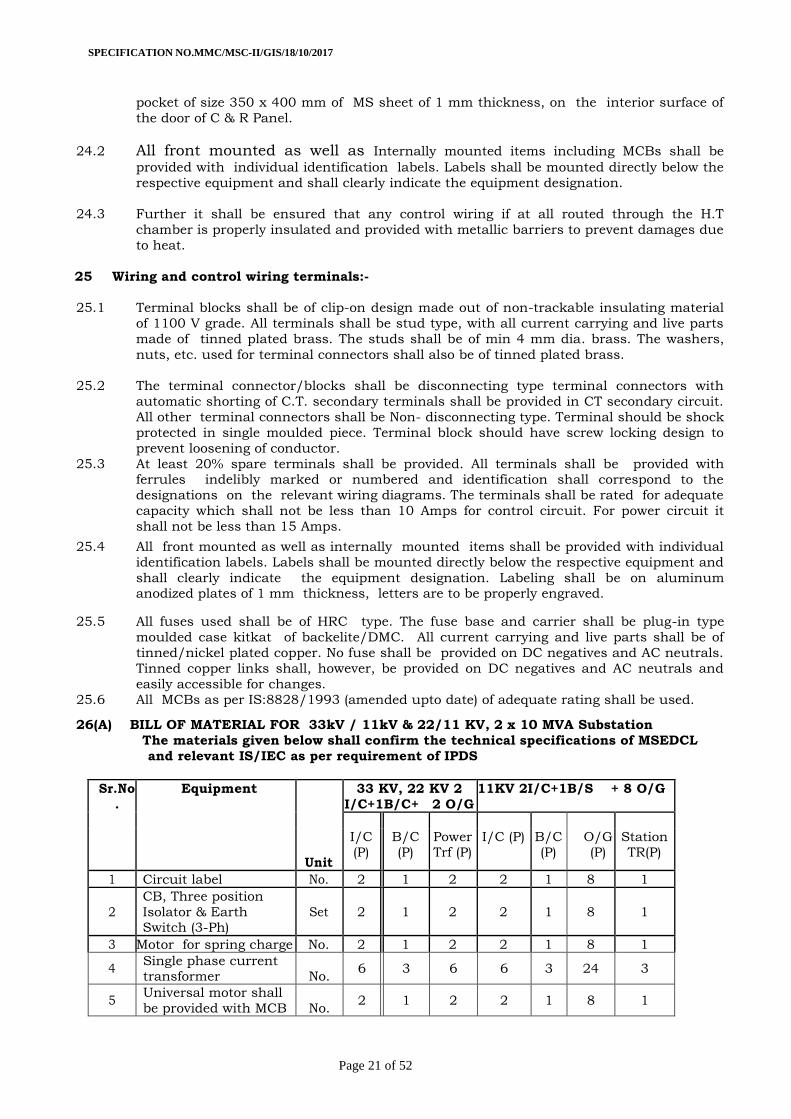
26(A) BILL OF MATERIAL FOR 33kV / 11kV & 22/11 KV, 2 x 10 MVA Substation
The materials given below shall confirm the technical specifications of MSEDCL
and relevant IS/IEC as per requirement of IPDS
Sr.No
.
Equipment
Unit
33 KV, 22 KV 2
I/C+1B/C+ 2 O/G
11KV 2I/C+1B/S + 8 O/G
I/C (P)
B/C (P)
Power Trf (P)
I/C (P) B/C (P)
O/G (P)
Station TR(P)
1 Circuit label No. 2 1 2 2 1 8 1
2
CB, Three position
Isolator & Earth Switch (3-Ph)
Set 2 1 2 2 1 8 1
3 Motor for spring charge No. 2 1 2 2 1 8 1
4 Single phase current transformer No.
6 3 6 6 3 24 3
5 Universal motor shall
be provided with MCB No. 2 1 2 2 1 8 1
SPECIFICATION NO.MMC/MSC-II/GIS/18/10/2017
Page 22 of 52
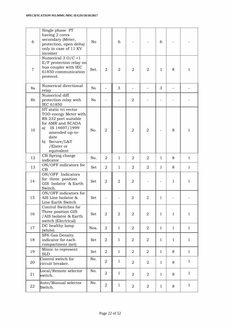
6
Single phase PT
having 2 cores
secondary (Meter,
protection, open delta) only in case of 11 KV
incomer
No 6 - - 6 - -
7
Numerical 3 O/C +1
E/F protection relay on
bus coupler with IEC
61850 communication
protocol.
Set. 2 2 2 2 1 8 1
8a Numerical directional
relay No - 3 - - 3 - -
8b
Numerical diff
protection relay with
IEC 61850
No - - 2 - - - -
10
HT static tri vector
TOD energy Meter with
RS 232 port suitable
for AMR and SCADA a) IS 14697/1999
amended up-to-
date
b) Secure/L&T
/Elster or equivalent
No. 2 - 2 2 - 8 1
12 CB Spring charge
indicator No. 2 1 2 2 1 8 1
13 ON/OFF indicators for
CB Set 2 1 2 2 1 8 1
14 4
4
ON/OFF Indicators
for three position
GIS Isolator & Earth
Switch.
Set 2 2 2 - - 1 1
15 ON/OFF indicators for AIS Line Isolator &
Line Earth Switch
Set - - 2 2 1 - -
16
Control Switches for
Three position GIS
/AIS Isolator & Earth
switch (Electrical)
Set 2 2 2 2 1 1 1
17 DC healthy lamp
(white) Nos. 2 1 2 2 1 1 1
18
SF6 Gas Density
indicator for each compartment (set)
Set 2 1 2 2 1 1 1
19 Mimic to represent
SLD Set 2 1 2 2 1 8 1
20 Control switch for
circuit breaker.
No. 2 1 2 2 1 8 1
21 Local/Remote selector
switch.
No. 2 1 2 2 1 8 1
22 Auto/Manual selector
Switch.
No. 2 1 2 2 1 8 1
SPECIFICATION NO.MMC/MSC-II/GIS/18/10/2017
Page 23 of 52
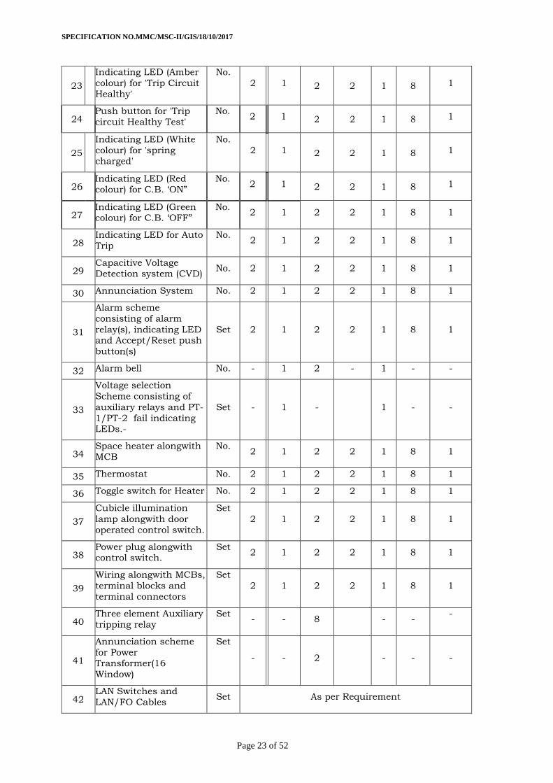
23
Indicating LED (Amber
colour) for 'Trip Circuit
Healthy'
No.
2 1 2 2 1 8 1
24 Push button for 'Trip
circuit Healthy Test'
No. 2 1 2 2 1 8 1
25
Indicating LED (White
colour) for 'spring charged'
No.
2 1 2 2 1 8 1
26 Indicating LED (Red colour) for C.B. ‘ON”
No. 2 1 2 2 1 8 1
27 Indicating LED (Green colour) for C.B. ‘OFF”
No. 2 1 2 2 1 8 1
28 Indicating LED for Auto
Trip
No. 2 1 2 2 1 8 1
29 Capacitive Voltage
Detection system (CVD) No. 2 1 2 2 1 8 1
30 Annunciation System No. 2 1 2 2 1 8 1
31
Alarm scheme
consisting of alarm
relay(s), indicating LED and Accept/Reset push
button(s)
Set 2 1 2 2 1 8 1
32 Alarm bell No. - 1 2 - 1 - -
33
Voltage selection
Scheme consisting of
auxiliary relays and PT-
1/PT-2 fail indicating LEDs.-
Set - 1 - 1 - -
34 Space heater alongwith
MCB
No. 2 1 2 2 1 8 1
35 Thermostat No. 2 1 2 2 1 8 1
36 Toggle switch for Heater No. 2 1 2 2 1 8 1
37
Cubicle illumination
lamp alongwith door
operated control switch.
Set
2 1 2 2 1 8 1
38 Power plug alongwith control switch.
Set 2 1 2 2 1 8 1
39
Wiring alongwith MCBs,
terminal blocks and
terminal connectors
Set
2 1 2 2 1 8 1
40 Three element Auxiliary
tripping relay
Set - - 8 - -
-
41
Annunciation scheme
for Power Transformer(16
Window)
Set
- - 2 - - -
42 LAN Switches and
LAN/FO Cables Set As per Requirement
-
SPECIFICATION NO.MMC/MSC-II/GIS/18/10/2017
Page 24 of 52
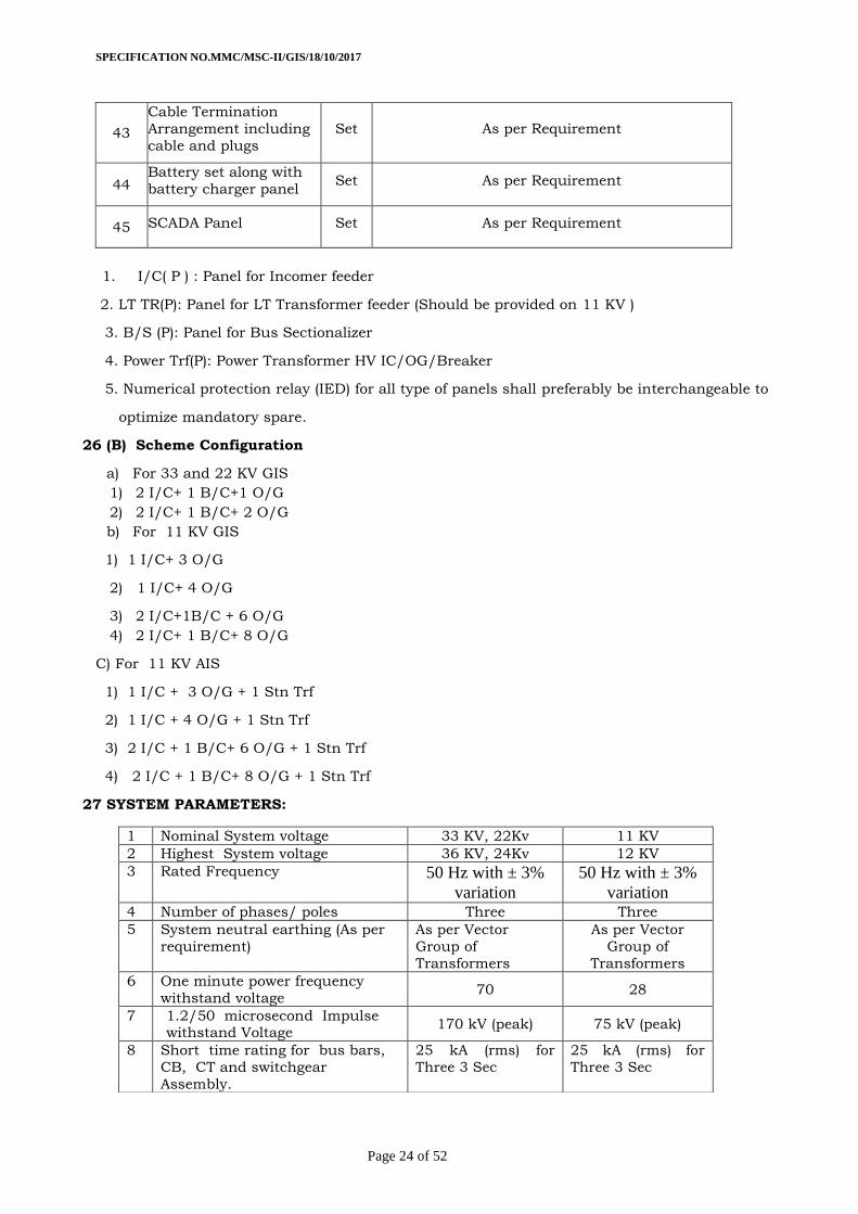
43
Cable Termination
Arrangement including
cable and plugs
Set As per Requirement
44 Battery set along with
battery charger panel Set As per Requirement
45 SCADA Panel Set As per Requirement
1. I/C( P ) : Panel for Incomer feeder
2. LT TR(P): Panel for LT Transformer feeder (Should be provided on 11 KV )
3. B/S (P): Panel for Bus Sectionalizer
4. Power Trf(P): Power Transformer HV IC/OG/Breaker
5. Numerical protection relay (IED) for all type of panels shall preferably be interchangeable to
optimize mandatory spare.
26 (B) Scheme Configuration
a) For 33 and 22 KV GIS
1) 2 I/C+ 1 B/C+1 O/G
2) 2 I/C+ 1 B/C+ 2 O/G
b) For 11 KV GIS
1) 1 I/C+ 3 O/G
2) 1 I/C+ 4 O/G
3) 2 I/C+1B/C + 6 O/G
4) 2 I/C+ 1 B/C+ 8 O/G
C) For 11 KV AIS
1) 1 I/C + 3 O/G + 1 Stn Trf
2) 1 I/C + 4 O/G + 1 Stn Trf
3) 2 I/C + 1 B/C+ 6 O/G + 1 Stn Trf
4) 2 I/C + 1 B/C+ 8 O/G + 1 Stn Trf
27 SYSTEM PARAMETERS:
1 Nominal System voltage 33 KV, 22Kv 11 KV
2 Highest System voltage 36 KV, 24Kv 12 KV
3 Rated Frequency 50 Hz with ± 3%
variation
50 Hz with ± 3%
variation
4 Number of phases/ poles Three Three
5 System neutral earthing (As per
requirement)
As per Vector
Group of
Transformers
As per Vector
Group of
Transformers
6 One minute power frequency
withstand voltage 70 28
7 1.2/50 microsecond Impulse withstand Voltage
170 kV (peak) 75 kV (peak)
8 Short time rating for bus bars,
CB, CT and switchgear
Assembly.
25 kA (rms) for
Three 3 Sec
25 kA (rms) for
Three 3 Sec
SPECIFICATION NO.MMC/MSC-II/GIS/18/10/2017
Page 25 of 52
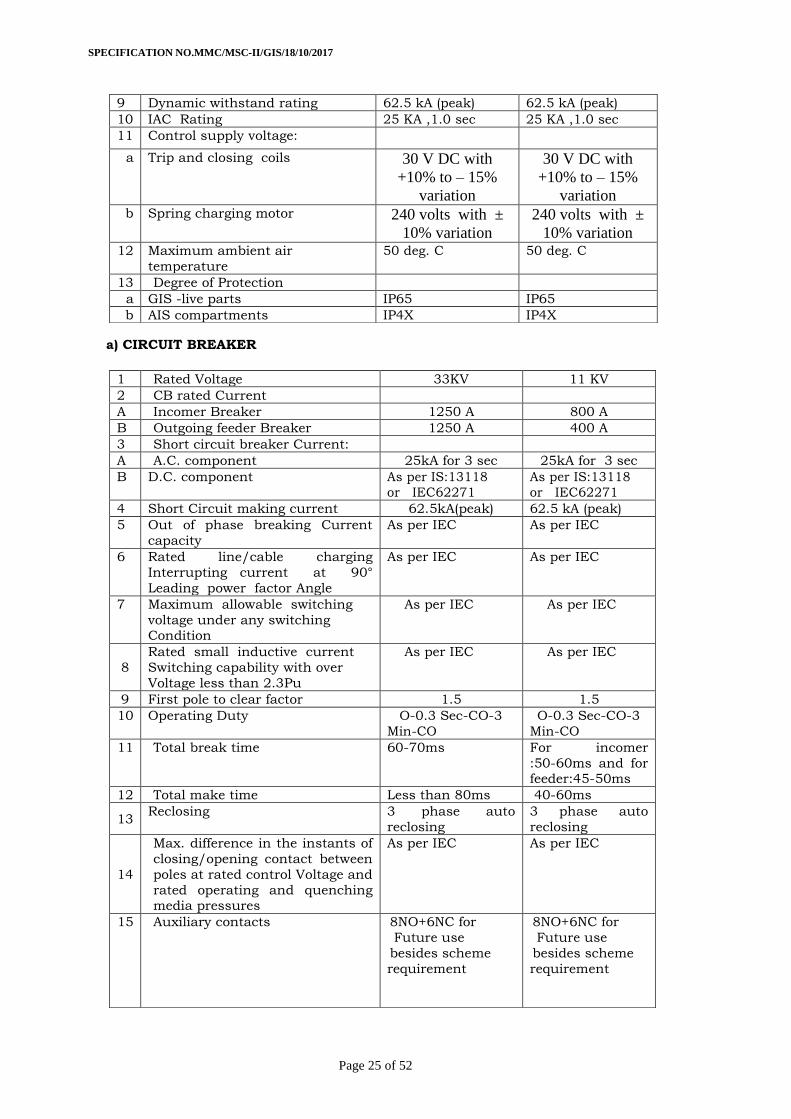
a) CIRCUIT BREAKER
9 Dynamic withstand rating 62.5 kA (peak) 62.5 kA (peak)
10 IAC Rating 25 KA ,1.0 sec 25 KA ,1.0 sec
11 Control supply voltage:
a Trip and closing coils 30 V DC with
+10% to – 15%
variation
30 V DC with
+10% to – 15%
variation
b Spring charging motor 240 volts with ±
10% variation
240 volts with ±
10% variation
12 Maximum ambient air
temperature
50 deg. C 50 deg. C
13 Degree of Protection
a GIS -live parts IP65 IP65
b AIS compartments IP4X IP4X
1 Rated Voltage 33KV 11 KV
2 CB rated Current
A Incomer Breaker 1250 A 800 A
B Outgoing feeder Breaker 1250 A 400 A
3 Short circuit breaker Current:
A A.C. component 25kA for 3 sec 25kA for 3 sec
B D.C. component As per IS:13118 or IEC62271
As per IS:13118 or IEC62271
4 Short Circuit making current 62.5kA(peak) 62.5 kA (peak)
5 Out of phase breaking Current
capacity
As per IEC As per IEC
6 Rated line/cable charging
Interrupting current at 90°
Leading power factor Angle
As per IEC As per IEC
7 Maximum allowable switching
voltage under any switching Condition
As per IEC As per IEC
8
Rated small inductive current
Switching capability with over
Voltage less than 2.3Pu
As per IEC As per IEC
9 First pole to clear factor 1.5 1.5
10 Operating Duty O-0.3 Sec-CO-3
Min-CO
O-0.3 Sec-CO-3
Min-CO
11 Total break time 60-70ms For incomer
:50-60ms and for feeder:45-50ms
12 Total make time Less than 80ms 40-60ms
13 Reclosing 3 phase auto
reclosing
3 phase auto
reclosing
14
Max. difference in the instants of
closing/opening contact between
poles at rated control Voltage and
rated operating and quenching media pressures
As per IEC As per IEC
15 Auxiliary contacts 8NO+6NC for
Future use
besides scheme
requirement
8NO+6NC for
Future use
besides scheme
requirement
SPECIFICATION NO.MMC/MSC-II/GIS/18/10/2017
Page 26 of 52
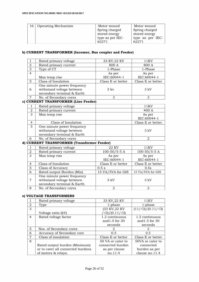
b) CURRENT TRANSFORMER (Incomer, Bus coupler and Feeder)
c) CURRENT TRANSFORMER (Line Feeder)
d) CURRENT TRANSFORMER (Transformer Feeder)
e) VOLTAGE TRANSFORMERS
16 Operating Mechanism Motor wound
Spring charged
stored energy
type as per IEC-62271
Motor wound
Spring charged
stored energy
type as per IEC-62271
1 Rated primary voltage 33 KV,22 KV 11KV
2 Rated primary current 800 A 800 A
3 Type of CT 1-Phase 1-Phase
4
Max temp rise
As per
IEC:60044-1
As per
IEC:60044-1
5 Class of Insulation Class E or better Class E or better
6
One minute power frequency
withstand voltage between
secondary terminal & Earth
3 kv 3 kV
7 No. of Secondary cores 3 3
1 Rated primary voltage 11KV
2 Rated primary current 400 A
3 Max temp rise As per
IEC:60044-1
4 Class of Insulation Class E or better
5 One minute power frequency
withstand voltage between
secondary terminal & Earth
3 kV
6 No. of Secondary cores 2
1 Rated primary voltage 22 KV 11KV
2 Rated primary current 100-50/5-5 A 100-50/5-5 A
3 Max temp rise As per
IEC:60044-1
As per
IEC:60044-1
4 Class of Insulation Class E or better Class E or better
5 Class of Accuracy 0.5 s 0.5s
6 Rated output Burden (Min) 15 VA/5VA for GIS 15 VA/5VA for GIS
7
One minute power frequency
withstand voltage between
secondary terminal & Earth
3 kV 3 kV
8 No. of Secondary cores 2 2
1 Rated primary voltage 33 KV,22 KV 11KV
2 Type 1-phase 1-phase
3
Voltage ratio (kV)
(33 KV,22 KV
/√3)/(0.11/√3)
(11/√3)/(0.11/√3)
4 Rated voltage factor 1.2 continuous and1.5 for 30
seconds
1.2 continuous and1.5 for 30
seconds
5 Nos. of Secondary cores 2 2
6 Accuracy of Secondary core 0.5 0.5
7 Class of insulation Class E or better Class E or better
8
Rated output burden (Minimum)
or to cater all connected burdens
of meters & relays.
50 VA or cater to
connected burden
as per clause
no.11.4
50VA or cater to
connected
burden as per
clause no.11.4
SPECIFICATION NO.MMC/MSC-II/GIS/18/10/2017
Page 27 of 52
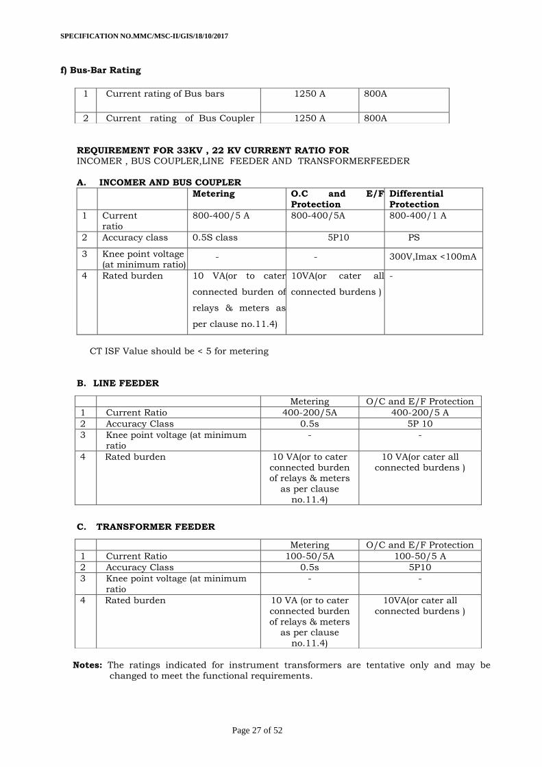
f) Bus-Bar Rating
REQUIREMENT FOR 33KV , 22 KV CURRENT RATIO FOR INCOMER , BUS COUPLER,LINE FEEDER AND TRANSFORMERFEEDER
A. INCOMER AND BUS COUPLER
Metering O.C and E/F
Protection
Differential
Protection
1 Current
ratio
800-400/5 A 800-400/5A 800-400/1 A
2 Accuracy class 0.5S class 5P10 PS
3 Knee point voltage (at minimum ratio)
- - 300V,Imax <100mA
4 Rated burden 10 VA(or to cater
connected burden of
relays & meters as
per clause no.11.4)
10VA(or cater all
connected burdens )
-
CT ISF Value should be < 5 for metering
B. LINE FEEDER
C. TRANSFORMER FEEDER
Notes: The ratings indicated for instrument transformers are tentative only and may be
changed to meet the functional requirements.
1 Current rating of Bus bars 1250 A 800A
2 Current rating of Bus Coupler 1250 A 800A
Metering O/C and E/F Protection
1 Current Ratio 400-200/5A 400-200/5 A
2 Accuracy Class 0.5s 5P 10
3 Knee point voltage (at minimum
ratio
- -
4 Rated burden 10 VA(or to cater
connected burden of relays & meters
as per clause
no.11.4)
10 VA(or cater all
connected burdens )
Metering O/C and E/F Protection
1 Current Ratio 100-50/5A 100-50/5 A
2 Accuracy Class 0.5s 5P10
3 Knee point voltage (at minimum
ratio
- -
4 Rated burden 10 VA (or to cater
connected burden
of relays & meters as per clause
no.11.4)
10VA(or cater all
connected burdens )
SPECIFICATION NO.MMC/MSC-II/GIS/18/10/2017
Page 28 of 52
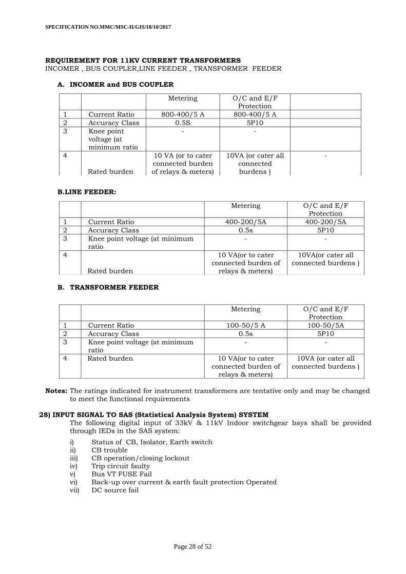
REQUIREMENT FOR 11KV CURRENT TRANSFORMERS
INCOMER , BUS COUPLER,LINE FEEDER , TRANSFORMER FEEDER
A. INCOMER and BUS COUPLER
B.LINE FEEDER:
B. TRANSFORMER FEEDER
Notes: The ratings indicated for instrument transformers are tentative only and may be changed
to meet the functional requirements
28) INPUT SIGNAL TO SAS (Statistical Analysis System) SYSTEM
The following digital input of 33kV & 11kV Indoor switchgear bays shall be provided
vi) Back-up over current & earth fault protection Operated
vii) DC source fail
Metering O/C and E/F Protection
1 Current Ratio 800-400/5 A 800-400/5 A
2 Accuracy Class 0.5S 5P10
3 Knee point
voltage (at
minimum ratio
- -
4
Rated burden
10 VA (or to cater
connected burden
of relays & meters)
10VA (or cater all
connected
burdens )
-
Metering O/C and E/F Protection
1 Current Ratio 400-200/5A 400-200/5A
2 Accuracy Class 0.5s 5P10
3 Knee point voltage (at minimum
ratio
- -
4
Rated burden
10 VA(or to cater
connected burden of
relays & meters)
10VA(or cater all
connected burdens )
Metering O/C and E/F
Protection
1 Current Ratio 100-50/5 A 100-50/5A
2 Accuracy Class 0.5s 5P10
3 Knee point voltage (at minimum ratio
- -
4 Rated burden 10 VA(or to cater
connected burden of
relays & meters)
10VA (or cater all
connected burdens )
SPECIFICATION NO.MMC/MSC-II/GIS/18/10/2017
Page 29 of 52
29) Scheme features:
1. Trip circuit supervision scheme shall be provided for each circuit breaker.
2 When two or more incomers are required at one station, suitable voltage selection scheme
to select the correct PT supply will be essential . Voltage selection scheme offered shall be
suitable to select (automatically) the PT supply as follows
a. Both incomers 'ON' and both PTs healthy- PT supply from respective incomer
shall feed all circuits in that section.
b. Both incomers 'ON' and one PT fails : PT supply shall change over, provided the
bus-section breaker is closed.
c. One incomer out, P.T. supply shall change over, provided the bus-section
breaker is closed.
d. PT supply to all the panels including the incomer shall be routed through the voltage selection scheme. When one of the PTs fails, the same shall be indicated
automatically by the respective PT fail indicating LED. All necessary
relays/contacts for above schemes shall be accommodated in empty chamber of
adopter panel inside front door.
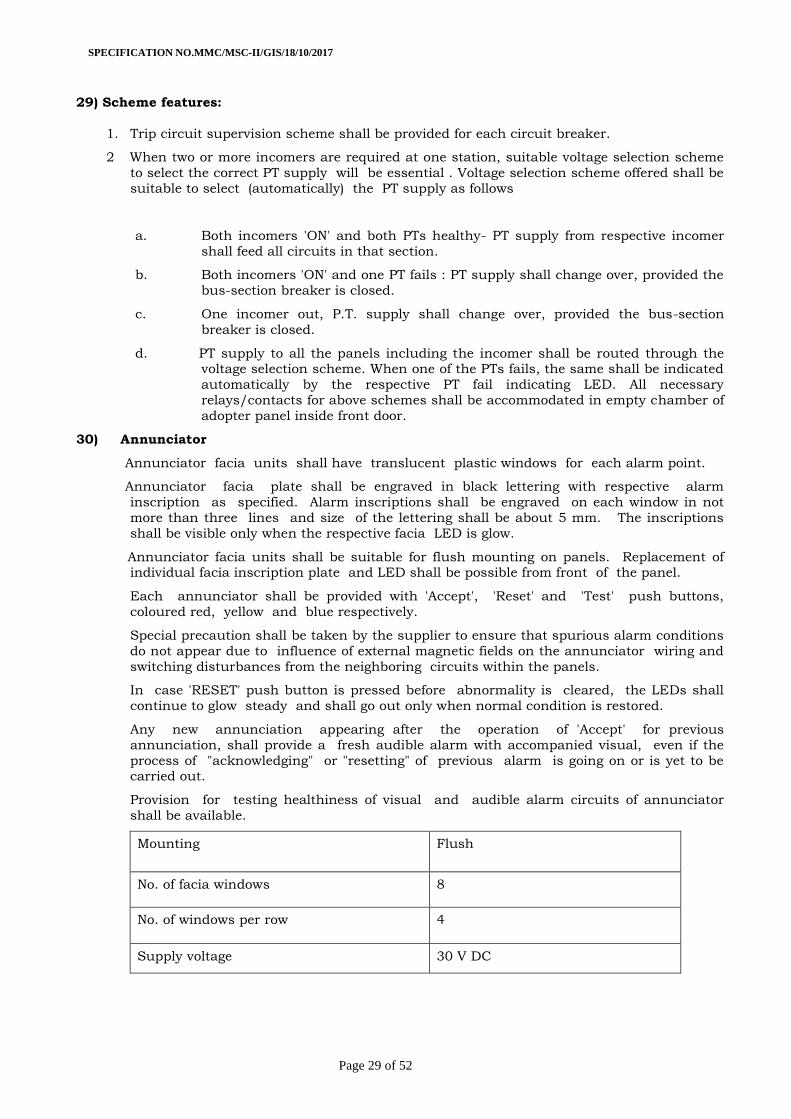
30) Annunciator
Annunciator facia units shall have translucent plastic windows for each alarm point.
Annunciator facia plate shall be engraved in black lettering with respective alarm
inscription as specified. Alarm inscriptions shall be engraved on each window in not
more than three lines and size of the lettering shall be about 5 mm. The inscriptions
shall be visible only when the respective facia LED is glow.
Annunciator facia units shall be suitable for flush mounting on panels. Replacement of individual facia inscription plate and LED shall be possible from front of the panel.
Each annunciator shall be provided with 'Accept', 'Reset' and 'Test' push buttons,
coloured red, yellow and blue respectively.
Special precaution shall be taken by the supplier to ensure that spurious alarm conditions
do not appear due to influence of external magnetic fields on the annunciator wiring and
switching disturbances from the neighboring circuits within the panels.
In case 'RESET' push button is pressed before abnormality is cleared, the LEDs shall
continue to glow steady and shall go out only when normal condition is restored.
Any new annunciation appearing after the operation of 'Accept' for previous
annunciation, shall provide a fresh audible alarm with accompanied visual, even if the
process of "acknowledging" or "resetting" of previous alarm is going on or is yet to be carried out.
Provision for testing healthiness of visual and audible alarm circuits of annunciator
shall be available.
Mounting Flush
No. of facia windows 8
No. of windows per row 4
Supply voltage 30 V DC
SPECIFICATION NO.MMC/MSC-II/GIS/18/10/2017
Page 30 of 52
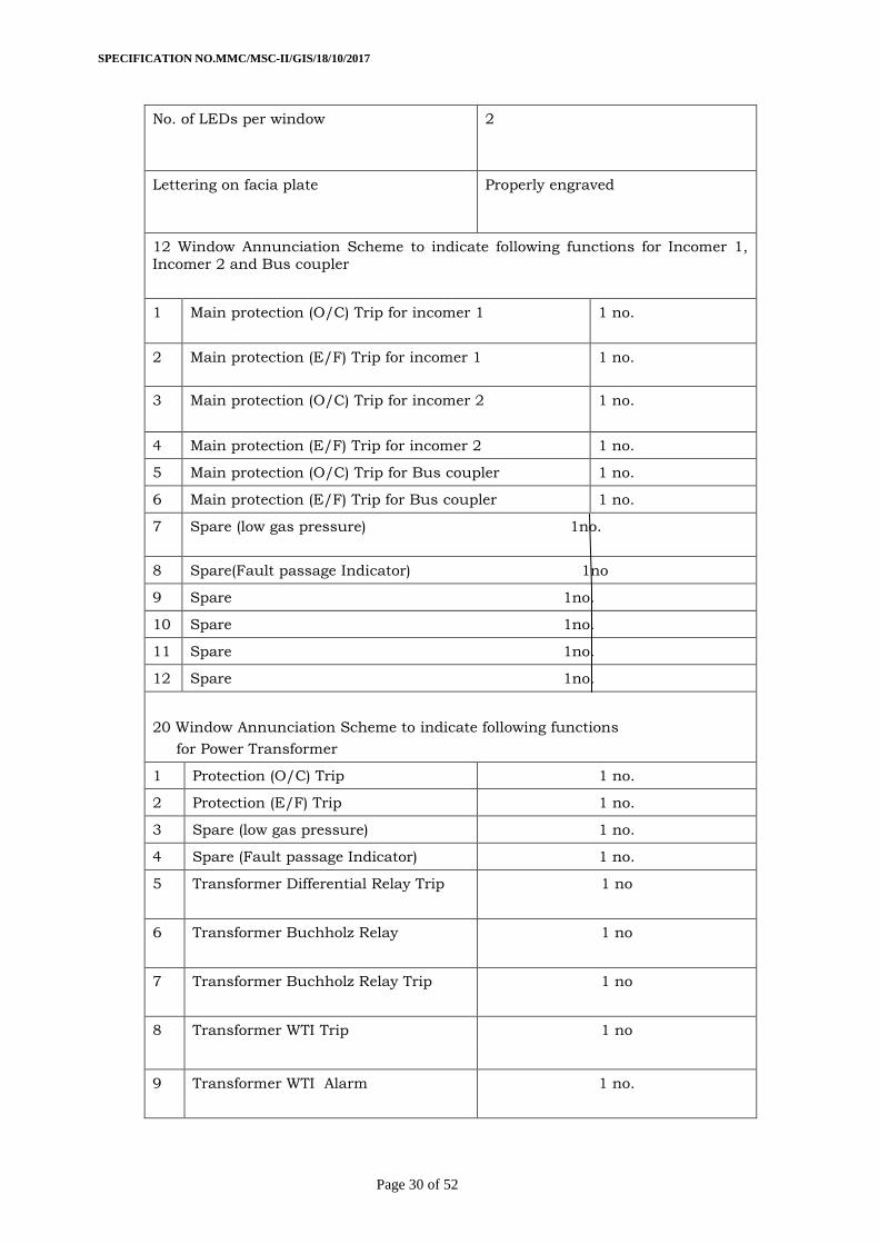
No. of LEDs per window 2
Lettering on facia plate Properly engraved
12 Window Annunciation Scheme to indicate following functions for Incomer 1,
Incomer 2 and Bus coupler
1 Main protection (O/C) Trip for incomer 1 1 no.
2 Main protection (E/F) Trip for incomer 1 1 no.
3 Main protection (O/C) Trip for incomer 2 1 no.
4 Main protection (E/F) Trip for incomer 2 1 no.
5 Main protection (O/C) Trip for Bus coupler 1 no.
6 Main protection (E/F) Trip for Bus coupler 1 no.
7 Spare (low gas pressure) 1no.
8 Spare(Fault passage Indicator) 1no
9 Spare 1no.
10 Spare 1no.
11 Spare 1no.
12 Spare 1no.
20 Window Annunciation Scheme to indicate following functions
for Power Transformer
1 Protection (O/C) Trip 1 no.
2 Protection (E/F) Trip 1 no.
3 Spare (low gas pressure) 1 no.
4 Spare (Fault passage Indicator) 1 no.
5 Transformer Differential Relay Trip
1 no
6 Transformer Buchholz Relay
1 no
7 Transformer Buchholz Relay Trip
1 no
8 Transformer WTI Trip 1 no
9 Transformer WTI Alarm
1 no.
SPECIFICATION NO.MMC/MSC-II/GIS/18/10/2017
Page 31 of 52
10 Transformer OTI Alarm
1 no.
11 Transformer OTI Trip
1 no.
12 Transformer PRV Trip
1 no.
13 OLTC Buchholz Relay Trip 1 no.
14 Transformer MOG Alarm 1 no.
15 Spare 1 no.
16 Spare 1 no.
17 Spare 1 no.
18 Spare 1 no.
19 Spare 1 no.
20 Spare 1 no.
12 Window Annunciation Scheme to indicate following functions
for Outgoing Feeder 1,2,3 & 4
1 Main protection (O/C) Trip for feeder 1. 1 no.
2 Main protection (E/F) Trip for feeder 1. 1 no.
3 Main protection (O/C) Trip for feeder 2. 1 no.
4 Main protection (E/F) Trip for feeder 2. 1 no.
5 Main protection (O/C) Trip for feeder 3. 1 no.
6 Main protection (E/F) Trip for feeder 3. 1 no.
7 Main protection (O/C) Trip for feeder 4. 1 no.
8 Main protection (E/F) Trip for feeder 4. 1 no.
9 Spare 1 no.
10 Spare 1 no.
11 Spare 1 no.
12 Spare 1 no.
12 Window Annunciation Scheme to indicate following functions
for Outgoing Feeder 5,6,7 & 8
1 Main protection (O/C) Trip for feeder 5. 1 no.
2 Main protection (E/F) Trip for feeder 5. 1 no.
3 Main protection (O/C) Trip for feeder 6. 1 no.
4 Main protection (E/F) Trip for feeder 6. 1 no.
5 Main protection (O/C) Trip for feeder 7. 1 no.
SPECIFICATION NO.MMC/MSC-II/GIS/18/10/2017
Page 32 of 52
6 Main protection (E/F) Trip for feeder 7. 1 no.
7 Main protection (O/C) Trip for feeder 8 1 no.
8 Main protection (E/F) Trip for feeder 8. 1 no.
9 Spare 1 no.
10 Spare 1 no.
11 Spare 1 no.
12 Spare 1 no.
31 Type TESTS
The panel shall be fully type tested as per relevant latest IEC standards 60056,62271-
102,60265,62271-200,62271-105,60529 and 60694 following type test reports shall be submitted with the technical bid. These tests must have been conducted on the offered
item in the NABL approved laboratory within last seven years prior to date of validity of
the offer.
LIST OF TYPE TESTS
Sr.
No
Name of Test
A Switchgear Panel(With Circuit Breaker installed)
a) Short Circuit Duty test
b) Short time and peak withstand current test
c) Power frequency withstand test
d) Lightening impulse withstand test
e) Temperature rise test
f) Internal Arc test as per IEC 62271-2009for 1 second)
g) Measurement of resistance main circuit
h)
Test to verify pressure relief operation of the panel (During internal arc
test)
i) Cable charging test
j) Short circuit withstand test of earthing device
k) Dielectric test
l) Capacitor bank current switching test
m) Single phase making and breaking test
B Circuit Breaker
a) Mechanical Endurance Test
SPECIFICATION NO.MMC/MSC-II/GIS/18/10/2017
Page 33 of 52
31.1 All the equipment’s offered shall be fully type tested as per the relevant standards,
amended up-to-date. The supplier shall furnish the type test reports and certificate of accreditation issued by the testing authority along with the offer. These tests must not
have been conducted earlier than seven years from the date of opening of bids.
31.2 In case these type tests are conducted earlier than seven years, all the type tests as per
the relevant standards shall be carried out by the successful bidder in the presence of
purchaser’s representative at free of cost before commencement of supply. The
undertaking to this effect should be furnished along with the offer without which the offer shall be liable for rejection.
31.3 The Purchaser reserves the right to demand repetition of some or all the type tests in the
presence of his representative. For this purpose the supplier may quote unit rates for
carrying out each type test.
31.4 For any change in the design/type already type tested and the design/type offered
against this specification, the purchaser reserves the right to demand repetition of
tests without any extra cost before commencement of supply. In this case the bidder
shall bring out in his offer all such changes made in components, materials, design
etc. as the case may be.
31.5 The company shall have the option to carry out various tests including type tests as per specification on the samples selected at random from the supplies effected, to ensure that
the supplies conform in quality and workmanship to the relevant specification. The
testing shall be done at an independent laboratory at company’s cost. Due notice shall
be given to supplier for such sample selection and such testing thereof to enable him to
be present for the same if so desired by him. If the supplier or his authorized representative fails to attend the sample selection and testing, the same shall be carried
out unilaterally by the company and the result thereof shall be binding upon the
C Current Transformer
a) Short time current test
b) Temperature Rise test
c) Lightning impulse withstand test
D Potential Transformer
a) Temperature Rise test
b)
Lightning impulse withstand test
E
Switchgear panel Degree of protection
a)
IP 4X test for LV and IP 65 for HV live Part.
F
Trivector Meter The Trivector meter shall conform all the requirements and type test
reports as per relevant IS/IEC amended upto date and as per technical
specifications of MSEDCL.
G Protection Relays
The Protection Relays shall conform all the requirements and type test
reports as per relevant IS/IEC amended upto date.
SPECIFICATION NO.MMC/MSC-II/GIS/18/10/2017
Page 34 of 52
supplier. In case the sample selected from the supplies fails to withstand the required
tests, then:-
a. For first time failure of sample, supplier shall have to replace the full quantity of the respective inspected lot supplied to various Stores and
lying unused at Stores.
b. For the quantity already accepted against the order and used,
deduction in price of 10% of the value of material supplied shall be
made.
AND
c. In respect of further supplies made against the order, if failure of
samples is noticed (i.e., second time failure against the order) then the
quantity lying unused at various Stores shall be rejected.
d. For the quantity already accepted against the order and used,
deduction in price of 10% of the value of material supplied shall be made.
e. Balance quantity against the order including the rejected qty. shall be
cancelled without any liability on either side.
f. The firm will be debarred from dealing with the company upto a period
of three years from the date of rejection.
32 Installation/Commissioning Checks / Tests The installation/commissioning of the 33 kV GIS are to be supervised by original
manufacturer, providing the manufacturer’s specialist for the above shall be supply
contractors responsibility and in accordance with contract specification, scope of supply
and price schedule.
After installation of panels, power and Control wiring and connections, Contractor shall perform commissioning checks as listed below to verify proper operation of switchgear /
panels and correctness of all equipment in all respects. In addition, the Contractor shall
carry out all other checks and tests recommended by the manufacturers.
32.1 General
a. Check name plate details according to specification.
b. Check for physical damage
c. Check tightness of all bolts, clamps and connecting terminal
d. Check earth connections
e. Check cleanliness of equipment
f. Check heaters are provided
g. H.V. test on complete switchboard with CT & breaker in position.
h. Check all moving parts are properly lubricated.
i. Check for alignment of busbars
j. Check continuity and IR value of space heater.
k. Check earth continuity for the complete switchgear board.
SPECIFICATION NO.MMC/MSC-II/GIS/18/10/2017
Page 35 of 52
32.2 Circuit Breaker
a. Check alignment
b. Check correct operation
c. Check control wiring for correctness of connections, continuity and IR values.
d. Manual operation of breakers completely assembled.
e. Power closing / opening operation, manually and electrically
f. Closing and tripping time.
g. Trip free and anti-pumping operation.
h. IR values, resistance and minimum pick up voltage of coils.
i. Simultaneous closing of all the three phases.
j. Check electrical and mechanical interlocks provided.
k. Checks on spring charging motor, correct operation of limit switches and time of
charging
l. All functional checks.
32.3 Current Transformers
a. I R test between windings and winding terminals to body.
b. Polarity tests.
c. Ratio identification checking of all ratios on all cores by primary injection of current.
d. Magnetization characteristics & secondary winding resistance.
e. Spare CT cores, if any to be shorted and earthed.
32.4 Voltage Transformers
a. Insulation resistance test.
b. Ratio test on all cores.
c. Polarity test.
b. Line connections as per connection diagram.
32.5 Cubicle Wiring
a. Check all switch operations
b. It should be made sure that the wiring is as per relevant drawings. All
interconnections between panels shall similarly be checked.
c. All the wires shall be IR Tested to earth.
d. Functional checking of all control circuit e.g. closing, tripping interlock,
supervision and alarm circuit including proper functioning of component /
equipment.
SPECIFICATION NO.MMC/MSC-II/GIS/18/10/2017
Page 36 of 52
e. Check terminations and connections.
f. Wire ducting.
g. Gap sealing and cable bunching for vermin proof.
32.6 Relays
a. Check internal wiring.
b. IR of all terminal body.
c. IR of AC to DC terminals
d. Check operating characteristics by secondary injection.
e. Check operation of electrical/ mechanical targets.
f. Relay settings.
33 INSPECTION
a. The inspection may be carried out by the purchaser at any stage of manufacture. The
successful Tenderer shall grant free access to the purchaser's representative/s at a
reasonable notice when the work is in progress. Inspection and acceptance of any
equipment under this specification by the purchaser, shall not relieve the supplier of his
obligation of furnishing equipment in accordance with the specification and shall not prevent subsequent rejection if the equipment is found to be defective.
b. The supplier shall keep the purchaser informed in advance, about the manufacturing
program so that arrangement can be made for stage inspection.
c. The purchaser reserves the right to insist for witnessing the acceptance/routine testing
of the bought out items. The supplier shall keep the purchaser informed, in advance, about such testing program.
34. FACTORY ACCEPTANCE & ROUTINE TESTS:
34.1 All acceptance and routine tests of equipment given in bill of material as per relevant
IS/IEC standards shall be carried out by the supplier in the presence of purchaser's
representative without any extra cost to the purchaser.(Note:- All measuring/testing equipment’s shall be of appropriate class of accuracy and shall have valid calibration
certificates which shall be produced to the Inspecting Officer for verification.)
34.2 After finalization of the program of type/acceptance/routine testing, the supplier shall
give three weeks advance intimation to the purchaser, to enable him to depute his
representatives for witnessing the tests.
34.3 The following Factory Acceptance Tests shall be carried out during inspection
1. Withstand Voltage at power frequency
2. Measurement of resistance of main circuit
3. Partial discharge test
4. Withstand voltage on the auxiliary circuits
5. Operational checks as per schematics
6. Operations of interlocks, signaling devices and auxiliary devices
7. Operation of VCB and three position Disconnector cum earth switch
8. Verification of wiring
9. Visual inspection
SPECIFICATION NO.MMC/MSC-II/GIS/18/10/2017
Page 37 of 52
35. QUALITY ASSURANCE PLAN
35.1 The tenderer shall invariably furnish information along with his offer, failing which his
offer shall be liable for rejection. Information shall be separately given for individual type and current rating of circuit breaker/CTs/PTs/Panel mounting & accessories.
35.2 Statement giving information about names of sub-suppliers, list of testing standards, list of
tests normally carried out in presence of tenderer's representative and copies of test
certificates in respect of following items of raw-materials.
a. Contact material
b. Porcelain 35.3 Information and copies of test certificates in respect of bought out accessories.
35.4 List of areas in manufacturing process, where joint stage inspections are normally carried
out by the tenderer/purchaser for quality control and details of such tests and
inspections.
35.5 Special features provided in the equipment to make it maintenance free.
35.6 List of testing equipment’s available with the tenderer for final testing of breakers vis-à-vis.
the type, special, acceptance and routine tests specified herein. The limitations in testing
facilities shall be very clearly brought out in schedule-E i.e. schedule of deviation from
specified test requirement.
The successful tenderer shall, within 30 days of placement of order, submit following
information to the purchaser.
List of raw materials as well as bought out accessories and the names of sub-suppliers
selected from those furnished along with the offer.
a. Type test certificates of the raw material and bought out accessories.
b. Quality assurance plan (QAP) with hold points for purchaser's inspection.
The quality assurance plan and purchaser's hold points shall be discussed between the purchaser and supplier, before it is finalized.
The successful tenderer shall submit the routine test certificates of bought out
accessories at the time of routine testing of the fully assembled breaker for the goods
manufactured within purchaser's country. The supplier shall also submit the central
excise passes for the raw material at the time of routine testing of the fully assembled
breaker.
36) PERFORMANCE GUARANTEE:
The equipment’s offered shall be guaranteed for satisfactory performance for a period of
66 months from the date of receipt of complete equipment at destination store/site in good
condition or 60 months from the date of satisfactory commissioning of equipment
whichever is earlier. The equipment’s found defective/failed within the above guarantee period shall be replaced/repaired by the supplier free of cost within one month of receipt
of intimation. If the defective/failed equipment’s are not replaced/repaired as per the
above guarantee clause, the company shall recover an equivalent amount plus 15 %
supervision charges from any of the supplier's bills.
37) DOCUMENTATION:
All drawings shall conform to international standards organization (ISO) 'A' series of drawing sheet/Indian Standards Specification IS 656. All drawings shall be in ink and suitable for
micro filming. All dimensions and data shall be in System International Units.
38) DRAWINGS:
38.1 The tenderer shall furnish four sets of relevant descriptive and illustrative published
literature/pamphlets and the following drawings for preliminary study:
a. General outline drawings showing outside dimensions, shipping dimensions,
weights, and quantity of insulating media air receiver capacity and such other
prominent details.
SPECIFICATION NO.MMC/MSC-II/GIS/18/10/2017
Page 38 of 52
b. Sectional views showing the general constructional features of the circuit
breaker including operating mechanism, arcing chambers, contacts, with
lifting dimensions for maintenance.
c. Schematic diagrams of the scheme for control, supervision and reclosing.
d. Structural drawing, design calculations and loading data for support
structures.
e. Foundation drilling plan and loading data for foundation design.
f. Technical specifications of equipment and special tools explaining
construction features, principle of operation, special features etc.
g. Comprehensive QAP,GA,SLD/BOQ ,Gas schematic diagram, technical
broachers, building requirements, earth mat design, list of recommended
spares, special tools or fixtures, O&M manuals, environmental guide for
handling SF^ gas & decommissioning, estimated time schedule for
installation & commissioning & operation of complete GIS
h. Type test reports of circuit breakers along with a separate list showing all the
tests carried out with date & place of test.
i. Test reports, literatures and pamphlets of bought out items and raw
materials.
38.2 The successful tenderer shall, within 6 weeks of placement of order, submit THREE sets
of final versions of all the above said drawings in A-3 size, bill of material, packing list & all type test reports for purchaser’s approval to the office of Chief Engineer (MM Cell).
The purchaser shall communicate his comments/approval on the drawings to the supplier
within reasonable period. The supplier shall, if necessary, modify the drawings and
resubmit four copies of the modified drawings for purchaser’s approval within two weeks
from the date of purchaser’s comments. After receipt of purchaser’s approval, the supplier shall, within three weeks, submit 10 prints &two good quality reproducible of
the approved drawings and 10 sets of instructions manuals in respect of Circuit breaker
to the office of Chief Engineer (MM Cell).
38.3 The successful tenderer shall furnish in the form of nicely bound volumes, the manuals
covering erection, commissioning, operation and maintenance instructions and all
relevant information and drawings pertaining to the main equipment as well as auxiliary devices. Marked erection drawings shall identify the component parts of the equipment
as shipped to enable Engineer/Purchaser to carry out erection with his own personnel.
Each manual shall also contain one set of all the approved drawings type test reports
as well as acceptance test reports to corresponding consignment dispatched. The total
quantity of the operating manuals/approved drawings sets to be supplied by the supplier shall be equal to the number of three phase breakers of rating, ordered.
38.4 The manufacturing of the equipments shall be strictly in accordance with the approved
drawings and no deviation shall be permitted without the written approval of the
purchaser. All manufacturing and fabrication work in connection with the equipment
prior to the approval of the drawings shall be at the supplier’s risk.
38.5 Approval of drawings/work by the purchaser shall not relieve the supplier of any of his responsibility and liability for ensuring correctness and correct interpretation of the
drawings for meeting the requirements of the latest revisions of applicable standards,
rules and codes of practices.
39. PACKING AND FORWARDING:
39.1 The equipment shall be packed in suitable crates so as to withstand handling during
transport and outdoor storage during transit. The supplier shall be responsible for any
damage to the equipment during transit, due to improper and inadequate packing. The
easily damageable materials shall be carefully packed and marked with the appropriate
caution symbols. Wherever necessary, proper lifting arrangement such as lifting hooks
SPECIFICATION NO.MMC/MSC-II/GIS/18/10/2017
Page 39 of 52
etc. shall be provided. Any material found short inside the packing cases shall be
supplied by supplier without any extra cost.
39.2 Each consignment shall be accompanied by a detailed packing list containing the following information:
a. Name of the consignee.
b. Details of consignment.
c. Destination.
d. Total weight of consignment.
e. Sign showing upper/lower side of the crate.
f. Handling and unpacking instructions.
g. Bill of materials indicating contents of each package and spare materials
The supplier shall ensure that the packing list and bill of materials are approved by the
purchaser before dispatch.
40) SUPERVISORY ERECTION AND COMMISSIONING;
The erection and commissioning of the breakers shall be supervised, if required by the
Purchaser, through one work-trained Engineer/foreman who shall direct the sequence of
erection and make necessary adjustments to the apparatus and correct in the field any
errors or omissions on the part of the tenderer in order to make the equipment and
material properly perform in accordance with the intent of this specification. The
representative shall also instruct the plant operators in the operation and maintenance of equipment furnished. Skilled workers, all the ordinary tools, equipment and cranes
required for breaker erection, shall be provided by the purchaser. Apart from the above,
the purchaser shall not be responsible for any other expenses incurred by the tenderer
and expenses such as Erector's salary, insurance against personal injuries to the
Erector etc., shall be to tenderer's account. Special tools, if required for erection and commissioning shall be arranged by the supplier at his cost. The supplier shall be
responsible for any damage to the breaker on commissioning, if it results from faulty or
improper assembly unless the erector can conclusively prove that the damage has
occurred on account of intentional mistake on the part of the skilled workers provided by
the purchaser.
41) Training to the MSEDCL staff
Onsite training as well as factory training should be provided by the
manufacturer/supplier to the operating staff of field and testing Engineers at free of cost.
If any miscellaneous accessories required for commissioning at site, no additional cost
will be paid.
SPECIFICATION NO.MMC/MSC-II/GIS/18/10/2017
Page 40 of 52
BIDDING SCHEDULE (To be filled in and signed by the Bidder)
SCHEDULE ‘A’
SCHEDULE OF GUARANTEED TECHNICAL PARTICULARS FOR GAS INSULATED SWITCHGEAR.
Sr No Particulars To be Filled by BIDDER
1 General:
`i Name of manufacturer
ii Factory address
iii GIS
iv Type /Model
v Indoor Installation
vi Standards applicable
vii Voltage level 33kv/11kv
2 Configuration:
i Number of 33kv/22 kV Incomer bays
ii Number of 33kv/ 22 kV Bus coupler
iii Number of transformer bays
iv Number of 11 kv Incomer bays
v Number of 11 kv Bus coupler
vi Number of 11 kv Feeder bay
vii Number of Current transformer
viii Number of Potential transformer
ix Future extension possibility
3 System particulars:
i Nominal system voltage
ii Corresponding highest system voltage
iii Frequency
iv Number of phases
v Neutral earthling
vi Short Current Rating
4 Auxiliary supplies:
i A. C. Supply
ii D.C. Supply
5 Service conditions:
i Max. ambiant température in Deg. C
ii Min ambiant température in Deg. C
iii Max daily average ambient temperature in Deg. C
iv Min yearly average ambient temperature in Deg. C
v Max. relative humidity in %
vi Max. annual rainfall in MM
vii Max. wind pressure in kg/sq. m.
viii Max. altitude above mean sea level in mtrs.
ix Isoceraunic level
x Seismic level (Horizontal acceleration)
6 GIS SWITCHGEAR PANEL:
i Material used for SF6 gas insulated metal enclosed switchgear
ii Size of Material
iii Minimum operating SF6 gas pressure in Bar
iv Alarm and trip pressure of SF6 in Bar
v Maximum leakage rate of SF6 gas per year in %
SPECIFICATION NO.MMC/MSC-II/GIS/18/10/2017
Page 41 of 52
vi SF6 accommodating the primary switching devices ( Busbar, VCB and Three position disconnector cum earthing switch) and all live parts.
vii Ingress protection min
viii Non-Return Valve shall be provided for SF6 gas filling at site
ix Height of switchgear panel in MM
x Powder coated with thickness in micron
xi Paint shade of Indoor Switchgear
xii Short time current rating
7 Busbar:
A) 33 KV /22KV busbars:
i Continuous current rating of busbar in Amps
ii Short time current rating of busbar in KA
iii Material of busbar
iv Size of busbars
v Cross sectional area of busbars in sq.mm
vi Current density of busbar in Amps/sq. mm
vii Space between busbar in mm
viii Silicon coating if busbar is placed outside the gas chambers
ix Support insulator Kv rating
x Material of support insulator and Creepage distance
xi Cantilever strength of support insulator in KgF
B) 11Kv busbars :
i Continuous current rating of busbar in Amps
ii Short time current rating of busbar in KA
iii Material of busbar
iv Size of busbars
v Cross sectional area of busbars in sq.mm
vi Current density of busbar in Amps/sq. mm
vii Space between busbar in mm
viii Silicon coating if busbar is placed outside the gas chambers
ix Support insulator Kv rating
SPECIFICATION NO.MMC/MSC-II/GIS/18/10/2017
Page 42 of 52
x Material of support insulator and Creepage distance
xi Cantilever strength of support insulator in KgF
8 Circuit Breaker :
A) 33 KV/22KV Circuit Breaker:
i Make of Vacuum Circuit Breaker
ii Make of Vacuum Interrupter
iii Rated voltage of Circuit Breaker
iv Maximum continuous voltage of Circuit Breaker
v Rated Continuous current of Circuit Breaker
vi Total break time
vii Total make time
viii Rated Symmetrical Short Circuit Breaking Current of Circuit Breaker for 3 seconds
ix Rated Operating Sequence of Circuit Breaker
x First pole to clear factor of Circuit Breaker
xi Peak Voltage of transient recovery voltage of Circuit Breaker
xii Rated Symmetrical Short Circuit Making Current of Circuit Breaker
xiii Power frequency withstand voltage for 1 min of Circuit Breaker
xiv Impulse withstand voltage of Circuit Breaker
xv Type of closing mechanism
xvi Voltage rating and Burden of spring released coil
xvii Voltage rating and watts of spring charging motor
xviii Voltage rating and Burden of tripping coil used in Circuit Breaker
B) 11 Kv Circuit Breaker:
i Make of Vacuum Circuit Breaker
ii Make of Vacuum Interrupter
iii Rated voltage of Circuit Breaker
iv Maximum continuous voltage of Circuit Breaker
v Rated Continuous current of Circuit Breaker
vi Total break time
vii Total make time
SPECIFICATION NO.MMC/MSC-II/GIS/18/10/2017
Page 43 of 52
viii Rated Symmetrical Short Circuit Breaking Current of Circuit Breaker for 3 seconds
ix Rated Operating Sequence of Circuit Breaker
x First pole to clear factor of Circuit Breaker
xi Peak Voltage of transient recovery voltage of Circuit Breaker
xii Rated Symmetrical Short Circuit Making Current of Circuit Breaker
xiii Power frequency withstand voltage for 1 min of Circuit Breaker
xiv Impulse withstand voltage of Circuit Breaker
xv Type of closing mechanism
xvi Voltage rating and Burden of spring released coil
xvii Voltage rating and watts of spring charging motor
xviii Voltage rating and Burden of tripping coil used in Circuit Breaker
xix For AIS Switchgear Circuit Breaker shall be horizontal draw out
9 CURRENT TRANSFORMERS:
A Current Transformer for 33kv /22 KV incomer/ bus coupler panel:
i Make of Current Transformer
ii Type of Current Transformer
iii Designation of Current Transformer.
iv Rated Insulation level of Current Transformer
v Current Transformer Ratio
vi VA Burden of core 1 of Current Transformer in VA
vii VA Burden of core 2 of Current Transformer in VA
viii Accuracy class for core 1
ix Accuracy class for core 2
x Limitation of exciting current of Current Transformer
xi Material use for primary/secondary winding of Current Transformer
xii Cross section of primary winding of Current Transformer
SPECIFICATION NO.MMC/MSC-II/GIS/18/10/2017
Page 44 of 52
xiii Size of primary winding of Current Transformer
xiv Cross section of secondary winding of Current Transformer
xv Size of secondary winding of Current Transformer
xvi Short Time Current rating of Current Transformer
xvii I. S. F. at lower ratio of Current Transformer
xviii Type of Insulation Housing of Current Transformer
B Current Transformer for 11 kv incomer/ bus coupler panel:
i Make of Current Transformer
ii Type of Current Transformer
iii Designation of Current Transformer.
iv Rated Insulation level of Current Transformer
v Current Transformer Ratio
vi VA Burden of core 1 of Current Transformer in VA
vii VA Burden of core 2 of Current Transformer in VA
viii Accuracy class for core 1
ix Accuracy class for core 2
x Limitation of exciting current of Current Transformer
xi Material use for primary/secondary winding of Current Transformer
xii Cross section of primary winding of Current Transformer
xiii Size of primary winding of Current Transformer
xiv Cross section of secondary winding of Current Transformer
xv Size of secondary winding of Current Transformer
xvi Short Time Current rating of Current Transformer
xvii I. S. F. at lower ratio of Current Transformer
xviii Type of Insulation Housing of Current Transformer
SPECIFICATION NO.MMC/MSC-II/GIS/18/10/2017
Page 45 of 52
C Current Transformer for 11 kv Line Feeder panel:
i Make of Current Transformer
ii Type of Current Transformer
iii Designation of Current Transformer.
iv Rated Insulation level of Current Transformer
v Current Transformer Ratio
vi VA Burden of core 1 of Current Transformer in VA
vii VA Burden of core 2 of Current Transformer in VA
viii Accuracy class for core 1
ix Accuracy class for core 2
x Limitation of exciting current of Current Transformer
xi Material use for primary/secondary winding of Current Transformer
xii Cross section of primary winding of Current Transformer
xiii Size of primary winding of Current Transformer
xiv Cross section of secondary winding of Current Transformer
xv Size of secondary winding of Current Transformer
xvi Short Time Current rating of Current Transformer
xvii I. S. F. at lower ratio of Current Transformer
xviii Type of Insulation Housing of Current Transformer
D Current Transformer for 33KV/22KV Transformer panel:
i Make of Current Transformer
ii Type of Current Transformer
iii Designation of Current Transformer.
iv Rated Insulation level of Current Transformer
v Current Transformer Ratio
vi VA Burden of core 1 of Current Transformer in VA
vii VA Burden of core 2 of Current Transformer in VA
viii Accuracy class for core 1
ix Accuracy class for core 2
x Limitation of exciting current of Current Transformer
xi Material use for primary/secondary winding of Current Transformer
xii Cross section of primary winding of Current Transformer
SPECIFICATION NO.MMC/MSC-II/GIS/18/10/2017
Page 46 of 52
xiii Size of primary winding of Current Transformer
xiv Cross section of secondary winding of Current Transformer
xv Size of secondary winding of Current Transformer
xvi Short Time Current rating of Current Transformer
xvii I. S. F. at lower ratio of Current Transformer
xviii Type of Insulation Housing of Current Transformer
10 Potential Transformer:
A Potential Transformer for 33kv /22k/11KV level :
i Make of Potential Transformer
ii Type of Potential Transformer
iii Designation of Potential Transformer
iv Rated insulation level of Potential Transformer
v Is offered Potential Transformer single phase units? (Yes/No)
vi Voltage Ratio of Potential Transformer
vii Nos. of Secondary cores of Potential Transformer
viii VA Burden of Core I of Potential Transformer in VA
ix VA Burden of Core 2 of Potential Transformer in VA
x Accuracy class of Core 1 of Potential Transformer
xi Accuracy class of Core 2 of Potential Transformer
xii Winding connection of Potential Transformer shall
xiii Rated Voltage factor and time of Potential Transformer
xiv Type of insulation housing of Potential Transformer
xv Whether HT fuses provided for Potential Transformer. (Yes/No)
xvi Material used for primary/secondary winding of Potential Transformer
xvii Cross section of primary winding of Potential Transformer
xviii Size of primary winding of Potential Transformer
SPECIFICATION NO.MMC/MSC-II/GIS/18/10/2017
Page 47 of 52
xix Cross section of secondary winding of Potential Transformer
xx Size of secondary winding of Potential Transformer
11 DISCONNECTORS
i Applicable standards
ii Type
iii Rated current in Amp for
iv - Bus disconnector
v - Line disconnector
vi - Transformer disconnector
vii - PT disconnector
viii Maximum Current that can be safely interrupted by the Isolator (Amp).
ix - Inductive
x - Capacitive
xi Rated Short time withstand Current in kA, for 3 sec
xii Rated peak short time Current, kAp
xiii Rated bus charging current, in Amp
xiv Type of contacts
xv Material of contacts
xvi Current Density at minimum cross section (A/mm2)
xvii Rated lightning impulse withstand voltage across the open gap, kVp
xviii Rated Power Freq withstand voltage across the open gap, kVrms
xix Mechanical Endurance class
xx Type of Operating Mechanism
xxi Operating Motor details
xxii - Type
xxiii - Rated Voltage
xxiv - Rated Current
xxv - Rated Watts
SPECIFICATION NO.MMC/MSC-II/GIS/18/10/2017
Page 48 of 52
xxvi Operating Time
xxvii - Closing - Opening
xviii Mechanical indication on drive shaft
12 Maintenance Grounding Switch
i Applicable standards
ii Type
iii Rate Short time withstand Current in kA, for 3 sec
iv Rated peak short time Current, kAp
v Rated lightning impulse withstand voltage across the open gap, kVp
vi Rated Power Freq withstand voltage across the open gap, kVrms
vii Type of Operating Mechanism
viii Operating Motor details
ix - Type
x - Rated Voltage
xi - Rated Current
xii - Rated Watts
xiii Operating Time
xiv - Closing
- Opening
xv Mechanical indication on drive shaft
13 Local Control Cubical
i Name of Manufacturer
ii Location in GIS
iii Material
iv Sheet Thickness
v Degree of Protection
vi Padlocking arrangement
vii Major components of LCC
SPECIFICATION NO.MMC/MSC-II/GIS/18/10/2017
Page 49 of 52
viii - Bay control mimic diagram
ix - Control Switches
x - Indicating lamps
xi - Position indicators
xii - Annunciation scheme
xiii - Auxiliary relays
xiv - Annunciation scheme
xv - Auxiliary relays
xvi - Contact multiplication relays
xvii - System parameters display
xviii - Heater with thermostat
xix - Interface terminal blocks for relaying &protection
14 GIS to Line connection
i No’s of XLPE cable can be terminated
ii Type of cable termination required
15 GIS to Transformer connection
i No’s of XLPE cable can be terminated
ii Type of cable termination required
16 Numerical Line Protection Relay:
i Make of non direction 3 O/C + 1 E/F relay.
ii Type of non direction 3 O/C + 1 E/F relay.
iii Designation of non direction 3 O/C + 1 E/F relay.
iv Setting of O/C elements of non direction 3 O/C + 1 E/F relay
v Setting of E/F elements of non direction 3 O/C + 1 E/F relay
SPECIFICATION NO.MMC/MSC-II/GIS/18/10/2017
Page 50 of 52
vi Characteristics of non direction 3 O/C + 1 E/F relay
vii Number of N/O & N/C contacts provided for non direction 3 O/C + 1 E/F relay.
viii DC Auxiliary Voltage of Non direction 3 O/C + 1 E/F relay
ix Operational indicator of non direction 3 O/C + 1 E/F relay
x Make of High speed Master Trip relay.
xi General Design of High speed Master Trip relay.
xii Designation of High speed Master Trip relay.
xiii Number of poles of High speed Master Trip relay
xiv C. T. Secondary current of High speed Master Trip relay
xv Time setting of High speed Master Trip relay.
xvi Frequency of High speed Master Trip relay
xvii Number of N/O & N/C contacts provided for High speed Master Trip relay
xviii DC Auxiliary Voltage of High speed Master Trip relay
xix Operational indicator of High speed Master Trip relay
17 Ammeter :
i Make of Ammeter
ii Size of Ammeter
iii Response time of Ammeter.
iv Ammeter shall be operable up to 55°C
v Dielectric strength of Ammeter
vi Make of Ammeter selector switch
vii Designation of Ammeter selector switch.
18 Voltmeter:
i Make of Voltmeter
ii Type of Voltmeter.
iii Size of Voltmeter.
iv Response time of Voltmeter
v Voltmeter shall be operable up to 55°C
vi Dielectric strength of Voltmeter
vii Make of Voltmeter selector switch
SPECIFICATION NO.MMC/MSC-II/GIS/18/10/2017
Page 51 of 52
viii Designation of Voltmeter selector switch.
19 Energy meter :
i Make of HT Trivector TOD energy meter.
ii Type & Designation of HT Trivector TOD energy meter .
iii Class of accuracy of HT Trivector TOD energy meter shall be 0.5
iv Measuring parameters of HT Trivector TOD energy meter.
v HT Trivector TOD energy meter shall have customized backlit liquid crystal display.
20 Digital Frequency Meter :
i Make of Digital Frequency Meter.
ii Size of Digital Frequency Meter.
iii Range of Digital Frequency Meter in Hz.
iv Type of Digital Frequency Meter.
v Display of Digital Frequency Meter shall be seven segment red colour LED Display with 0.5" height
21 Terminal Connector :
i Material of Terminal Connector shall be Nickel Plated Brass.
ii Size of stud of Terminal Connector shall be Minimum 4 mm dia.
iii Normal current capacity of terminal connector shall be 10 amps.
iv Breaking current capacity of terminal connector shall be 4 amps.
22 Maintenance :
i Maximum down time for replacement or removal of any part
ii Maximum down time for degassing and re-filling the biggest compartment
iii Time between two refilling of SF6 gas.
iv Recommended period for overhauling
v Operation and Maintenance manual attached
vi Nearest local service centre
vii Minimum time of availability of local service
viii Availability of spares at local service centre
ix List of recommended spares attached?
x List of recommended special tools, etc attached?
xi List of commission spares attached?
xii List of maintenance spares attached?
SPECIFICATION NO.MMC/MSC-II/GIS/18/10/2017
Page 52 of 52
23 Type Test Reports :
i Is Type Test Reports for Lightning Impulse Voltage Withstand test for switchgear panel (with circuit breaker installed) submitted?
ii Is Type Test Reports for Dry H.V. 1 min power frequency with stand test for switchgear panel (with circuit breaker installed) submitted?
iii Is Type Test Reports for Short time and peak withstand current test for switchgear panel (with circuit breaker installed) submitted?
iv Is Type Test Reports for Short Circuit Test with basic duties for switchgear panel (with circuit breaker installed) submitted?
v Is Type Test Reports for Single phase breaking capacity test for switchgear panel (with circuit breaker installed) submitted?
vi Is Type Test Reports for Temperature Rise Test for switchgear
panel (with circuit breaker installed) submitted?
vii Is Type Test Reports for capacitor current switching and cable charging Test for switchgear panel (with circuit breaker installed) submitted?
vii Is Type Test Reports for internal arc on busbar , breaker and cable chamber for switchgear panel (with circuit breaker installed) submitted?
viii Is Type Test Reports for Mechanical Endurance test for the offer circuit breaker installed) submitted?
ix Is Type Test Reports for Short Time Current test for Current Transformer submitted?
x Is Type Test Reports for Impulse Voltage Withstand Test for Current Transformer submitted?
xi Is Type Test Reports for Temperature Rise Test for Current Transformer submitted?
xii Is Type Test Reports for Impulse Voltage Withstand Test for Potential Transformer submitted?
xiii Is Type Test Reports for Temperature Rise Test for Potential Transformer submitted?
xiv Is test certificate in respect of current transformer submitted?
xv Is test certificate in respect of Potential Transformer submitted?