Complete Assemblies 30 Specifications Common to All A22/M22 The Following Pages Provide Information Common To Each Model of The A22/M22 Pushbutton Switch H A22 H A22S/W H A22K H M22 Specifications J APPROVED STANDARDS Recognized organization Standards File No. UL, cUL (See note) UL508 E41515 ASTA EN60947-5-1 — Note: UL: CSA C22 No. 14 J RATINGS Contacts (General-purpose Load) Rated carry Rated l Rated current (A) current voltage Utilization category AC15 (inductive load) AC12 (resistive load) DC13 (inductive load) DC12 (resistive load) 10 amps 24 VAC 10 10 — — 110 VAC 5 10 220 VAC 3 6 380 VAC 2 3 440 VAC 1 2 24 VDC — — 1.5 10 110 VDC 0.5 2 220 VDC 0.2 0.6 380 VDC 0.1 0.2 Note: 1. Rated current values are determined according to the testing conditions specified by JIS C4520. The above ratings were obtained by conducting tests under the following conditions as specified by JIS C4505. (1) Ambient temperature: 20°±2°C (2) Ambient humidity: 65±5% (3) Operating frequency: 20 operations/min 2. Minimum applied load: 10 mA, 5 VDC Contacts (Microload) Rated applied load Minimum applied load 50 mA, 5 VDC (Resistive load) 1 mA, 5 VDC LED Indicators without Transformer Rated voltage Rated current Operating voltage 6 VDC 60 mA 6 VDC±5% 6 VAC 60 mA 6 VAC/DC±5% 12 VAC/DC 30 mA 12 VAC/DC±5% 24 VAC/DC 15 mA 24 VAC/DC±5%
Transcript
Complete Assemblies
30
Specifications Common to All A22/M22
The Following Pages Provide Information CommonTo Each Model of The A22/M22 Pushbutton Switch
Note: 1. Rated current values are determined according to the testing conditions specified by JIS C4520. The above ratings wereobtained by conducting tests under the following conditions as specified by JIS C4505.(1) Ambient temperature: 20°±2°C(2) Ambient humidity: 65±5%(3) Operating frequency: 20 operations/min
2. Minimum applied load: 10 mA, 5 VDC
Contacts (Microload)
Rated applied load Minimum applied load
50 mA, 5 VDC (Resistive load) 1 mA, 5 VDC
LED Indicators without Transformer
Rated voltage Rated current Operating voltage
6 VDC 60 mA 6 VDC±5%
6 VAC 60 mA 6 VAC/DC±5%
12 VAC/DC 30 mA 12 VAC/DC±5%
24 VAC/DC 15 mA 24 VAC/DC±5%
All A22/M22 Assemblies All A22/M22 Assemblies
31
Incandescent Lamp
Rated voltage Rated current Operating voltage
6 VDC 200 mA 5 V
14 VAC/DC 80 mA 12 V
28 VAC/DC 40 mA 24 V
130 VAC/DC 20 mA 100 V
Transformer Lighting
Rated voltage Operational voltage Applicable lamp (BA8S/13j gold)
frequency Electrical 30 operations/min max. 30 operations/min max.
Insulation resistance 100 MΩ min. (at 500 VDC)
Dielectric strength 2,500 VAC, 50/60 Hz for 1 min between terminals of same polarity2,500 VAC, 50/60 Hz for 1 min between terminals of different polarity and also between each terminal andground
Vibration resistance(See note 2)
Malfunction: 10 to 55 Hz, 1.5-mm double amplitude (malfunction within 1 ms)
Shockresistance
Mechanical 1,000 m/s2100G
1,000 m/s2100G
1,000 m/s2 100G 1,000 m/s2100G
1,000 m/s2100G
1,000 m/s2100Gresistance
Malfunction(See note 2)
1,000 m/s2100G max.
600 m/s260G max.
250 m/s2 25G max. 1,000 m/s2100G max.
600 m/s260G max.
1,000 m/s2100G max.
Lifeexpectancy
Mechanical Momentary operation:5,000,000 operations min.
Momentary operation:300,000 operations min.
500,000operationsmin.
100,000operationsmin.
500,000operationsmin.
Electrical 500,000 operations min. 300,000operationsmin.
300,000operationsmin.
500,000operationsmin.
100,000operationsmin.
500,000operationsmin.
Ambient temperature(See note 1 )
Operating:-20°C to 70°C(-4°F to158°F)Storage:-40°C to 70°C(-40°F to158°F)
29.4 N 3.0 kgf 44.1 N 4.5 kgf 0.34 N S m3.5 kgf S cm(See note)
0.25 N S m2.5 kgf S cm fortwo position(See note)
0.34 N 3.5 gf(See note)
0.25 N S m2.5 kgf S cm forthree position(See note)
0.34 N S m3.5 kgf S cm forthree position
0.34 N S m3.5 kgf S cm forthree position
Total travel(TT)
5.5 mm max. 10±1 mm Approx. 90° for two position(Approx. 45° for three position)
Approx. 90° for two position
Releasing force(RF) min.
— 0.25 N S m max.2.5 kgf S cm(See note)
0.34 N S m max.3.5 kgf S cm(See note)
— 0.34 N S m max.3.5 kgf S cm(See note)
—
Note: Rotation torque for Emergency Stop Pushbutton, Knob-type Selector, and Key-type Selector Switches.
Accessories (Order Separately)Item Appearance Classification Remarks Part number
Contact Blocks SPST-NO General-pur-pose load
Provided as standard. OrderContact Blocks only whenddi l i h
A22-10
Microload
Contact Blocks only whenadding or replacing them. A22-10S
SPST-NC General-pur-pose load
A22-01
Microload A22-01S
DPST-NO General-pur-pose load
A22-20
Microload A22-20S
DPST-NC General-pur-pose load
A22-02
Microload A22-02S
Lamp Sockets Direct lighting Used when changing the light-i th d
A22-TNp
Transformerill i ti
110 VAC
g g ging method. A22-T1
illumination 220 VAC A22-T2
Mounting Latches For momentary models Provided as standard. OrderMounting Latches only whenmounting Contact Blocks orLamp Sockets that are pur-chased individually.
A22-3200
Legendl
Standardi
With Snap-inL d Pl
White Snap-in Legend Plate is acrylic. A22Z-3321gplateframes
sizep
Legend Plate(Without text)
Red
p g y
A22Z-3322frames (Without text)
Black A22Z-3323
Without Snap-in Legend Plate A22Z-3320
Largei
With Snap-inL d Pl
White A22Z-3331gsize
pLegend Plate(Without text)
Red A22Z-3332(Without text)
Black A22Z-3333
Without Snap-in Legend Plate A22Z-3330
(This table continues on the next page.)
All A22/M22 Assemblies All A22/M22 Assemblies
33
(continued from previous page)
Item Appearance Classification Remarks Part number
Lock fitting Round The body is equipped with aLock Fitting. This Lock Fitting isused when a more secure lockfeature is required.
A22Z-3360
Metallic bezel rings For flush or projection models Replace with the standardmodel.
A22Z-3580
For full-guard modelsmodel.Material: nickel-plated zinc A22Z-3582
Sealing caps For flush models Used to prevent dust or waterfrom entering the Operational
A22Z-3600F
For extended modelsfrom entering the OperationalUnit.Color: opaque
A22Z-3600T
For full-guard modelsColor: opaqueMaterial: silicon A22Z-3600G
Color lenses Red Used for changing the Opera-i l U i l f h P hb
A22Z-30TR
Green
g g ptional Unit color of the Pushbut-ton Switch
A22Z-30TG
Yellowton Switch.
A22Z-30TY
White A22Z-30TW
Blue A22Z-30TA
Three-throw spacers For Pushbutton Switches Used when mounting three Non-Illuminated Switch Units.Cannot be used with IlluminatedEmergency Stop Switches.
A22Z-3003
Hole plug Round Can be plugged into pre-cutpanel holes for future expan-sion. The color is black.
A22Z-3550
25 mm-dia. ring 25 mm ring Can be fit into a 25 mm-dia.hole in the panel. Since this isnot attached to the main body,order separately.
A22Z-R25
Snap-inl d
Standardi
Without text Black Attached to the Standard-sizeL d Pl F
A22Z-3443Bplegendplates
size Red Legend Plate Frame. A22Z-3443Rplates
White Material: Acrylic A22Z-3443W
Transparent A22Z-3443C
White text onred back
f A22Z-3443R-2red back-ground STOP A22Z-3443R-4
White text onbl k b k
| A22Z-3443B-1black back-ground
START A22Z-3443B-3ground
ON A22Z-3443B-5
OFF A22Z-3443B-6
UP A22Z-3443B-7
DOWN A22Z-3443B-8
POWER ON A22Z-3443B-9
OFF-ON A22Z-3443B-10
Largei
Without text Black Attached to the Large-size Leg-d Pl F
A22Z-3453Bgsize Red
g gend Plate Frame A22Z-3453R
White Material: Acrylic A22Z-3453W
Transparent A22Z-3453C
ForEmer-gencySt
60-dia. round plate with blackletters on a yellow back-ground
“EMERGENCY STOP” isengraved on the plate. Used asan Emergency Stop SwitchL d Pl t
A22Z-3466-1
g yStopSwitch 90-dia. round plate with black
letters on a yellow back-ground
g y pLegend Plate. A22Z-3476-1
(This table continues on the next page.)
All A22/M22 Assemblies All A22/M22 Assemblies
34
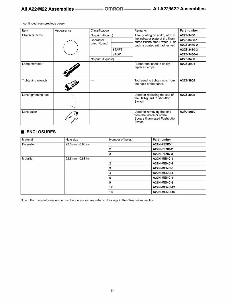
(continued from previous page)
Item Appearance Classification Remarks Part number
Character films No print (Round) After printing on a film, affix toh i di l f h Ill i
A22Z-3460
Characteri (R d)
|
p g ,the indicator plate of the Illumi-nated Pushbutton Switch (The
A22Z-3460-1print (Round) f
nated Pushbutton Switch. (Theback is coated with adhesive.) A22Z-3460-2
STARTback is coated with adhesive.)
A22Z-3460-3
STOP A22Z-3460-4
No print (Square) A22Z-3480
Lamp extractor — Rubber tool used to easilyreplace Lamps.
A22Z-3901
Tightening wrench — Tool used to tighten nuts fromthe back of the panel.
A22Z-3905
Lens tightening tool — Used for replacing the cap ofthe Half-guard PushbuttonSwitch.
A22Z-3908
Lens puller — Used for removing the lensfrom the indicator of theSquare Illuminated PushbuttonSwitch.
A3PJ-5080
J ENCLOSURES
Material Hole size Number of holes Part number
Polyester 22.5 mm (0.88 in) 1 A22N-PENC-1y ( )
2 A22N-PENC-2
3 A22N-PENC-3
Metallic 22.5 mm (0.88 in) 1 A22N-MENC-1( )
2 A22N-MENC-2
3 A22N-MENC-3
4 A22N-MENC-4
6 A22N-MENC-6
9 A22N-MENC-9
12 A22N-MENC-12
16 A22N-MENC-16
Note: For more information on pushbutton enclosures refer to drawings in the Dimensions section.
All A22/M22 Assemblies All A22/M22 Assemblies
35
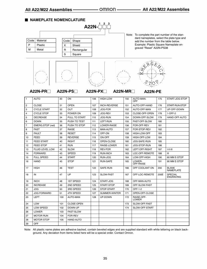
A22N-jjj1 2 3
Code Material
P Plastic
M Metal
Code Shape
X Shield
R Rectangular
S Square
A22N-PRj A22N-PSj A22N-PXj A22N-MRj A22N-PE
J NAMEPLATE NOMENCLATURE
Note: To complete the part number of the stan-dard nameplates, select the plate type andadd the number from the table below.Example: Plastic Square Nameplate en-graved “Reset” A22N-PS38
1 AUTO 30 ON 106 HIGH-LOW 150 AUTO-MAN-OFF
175 START-JOG-STOP
2 CLOSE 31 OPEN 107 INCH-REVERSE 151 AUTO-OFF-HAND 176 START-RUN-STOP
22 JOG FORWARD 51 4TH SPEED 127 SUMMER-WINTER 171 OPEN-OFF-CLOSE
23 LEFT 100 AUTO-MAN 128 UP-DOWN 172 RAISE-OFF-LOWER
24 LOW 101 CLOSE-OPEN 173 SLOW-OFF-FAST
25 LOW SPEED 102 DOWN-UP 174 SLOW-OFF-START
26 LOWER 103 FAST-SLOW
27 MOTOR RUN 104 FOR-REV
28 MOTOR STOP 105 HAND-AUTO
29 OFF
Note: All plastic name plates are adhesive backed, contain beveled edges and are supplied standard with white lettering on black back-ground. Any deviation from items listed here will be a special order. Contact Omron.
All A22/M22 Assemblies All A22/M22 Assemblies
36
DimensionsUnit: mm (inch)
J LEGEND PLATE FRAMESA22Z-332j A22Z-333j
22.2 dia.
22.2 dia.
28 dia.28 dia.
40.8(1.61)
20.5(1.81)
29.8(1.17)
27(1.06)
50.8(2.00)
20.5(1.81)
29.8(1.17)
27(1.06)
A22N-PRj
29.8 (1.17)
6.4 (0.25)
11.4 (0.45)
29.9 (1.18)
44.8 (1.76)
φ22.3 (0.88)
Note: Curved dashed line denotes difference between Rectangular and Rectangular to Round name plates.
InstallationJ MOUNTING THE PANELPanel Hole Dimensions
22 dia.(0.87)
25 dia.(0.98)
24.1(0.95)
22.3(0.88)
22.3(0.88) 25
(0.98)
3.2(0.13)
For 25 mm-dia. holes, always use 25 mm-dia. Rings. (Since thecutout dimensions are large, IP65 cannot be guaranteed unless25-dia. Rings are used.)
If outer surface treatment such as paint is applied to the panel,the panel dimensions after outer surface treatment must meet thespecified panel dimensions.
J MATRIX INSTALLATION1. The followingpanelholedimensionsapplywhenSwitchUnits
and the Standard-size Legend Plate Frame Lock Fitting aremounted.
30(1.18)
45(1.77)
A22N-PR, -MR, -PXA22Z30
(1.18)
41(1.61)
2. The following panel hole dimensions apply when theLarge-size Legend Plate Frame is mounted.
45(1.77)
45(1.77)
A22N-S30
(1.18)
41(1.61)
A22Z
Locking should be applied toward the Engraving Plate.
Note: The above dimensions are the smallest-possible mountingdimensions. However, these dimensions do not apply tolarge Pushbutton Switches. For large PushbuttonSwitches, determine the distance between holes, takingthe Operational Unit and Legend Plate Frame intoaccount.
J MOUNTING THE OPERATIONAL UNITON THE PANEL
Insert the Operational Unit from the front surface of the panel,insert the Lock Fitting and the mounting nut from the terminalside, then tighten the nut. Before tightening, check that the rubberwasher is present between the Operational Unit and the panel.
When using a Legend Plate Frame, put one rubber washer eachbetween the Legend Plate Frame and the panel and between theOperational Unit and the Legend Plate Frame. (One rubberwasher will be provided when one Legend Plate Frame isordered.)
Align the Lock Fitting with the groove in the casing, then insertthe Lock Fitting so that its edge is located on the panel side.
Tighten the mounting nut at a torque of 0.98 to 1.96 N • m 10 to20 kgf • cm.
When using a Lock Ring, replace with the supplied Lock Fitting,insert the projecting part into the lock slot, and then tighten themounting nut.
Hold hereMounting nut
Lock Fitting
Rubber washerPanel
Proj-ectingpart
Panel LockFitting
When the panel cutout dimension is 25 mm dia., remove thesupplied rubber washer and mount the 25 mm-dia. Ring asshown below. (Since the A22Z-R25 is not attached to the mainbody, order separately.)
Operational Unit
25-dia. Ring
Panel
Lock Fitting
Mounting nut
(A22Z-R25)
22.3 dia.
25 dia.
25 dia.
22.3 dia.
22.3 dia.
All A22/M22 Assemblies All A22/M22 Assemblies
44
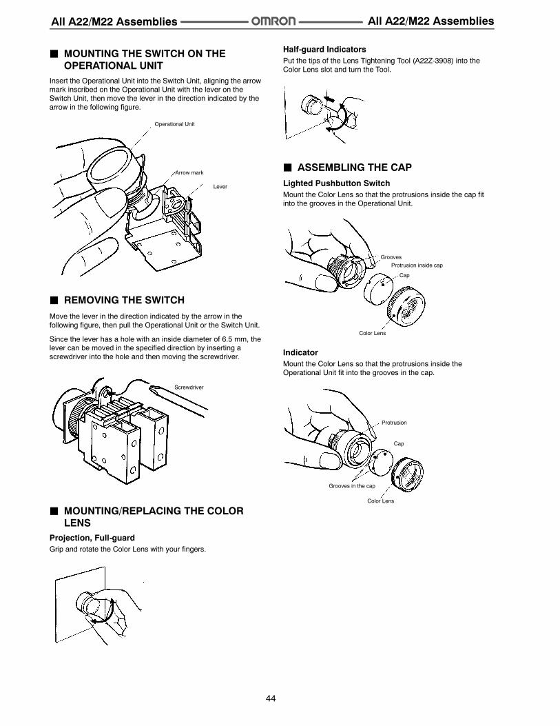
J MOUNTING THE SWITCH ON THEOPERATIONAL UNIT
Insert the Operational Unit into the Switch Unit, aligning the arrowmark inscribed on the Operational Unit with the lever on theSwitch Unit, then move the lever in the direction indicated by thearrow in the following figure.
Operational Unit
Arrow mark
Lever
J REMOVING THE SWITCHMove the lever in the direction indicated by the arrow in thefollowing figure, then pull the Operational Unit or the Switch Unit.
Since the lever has a hole with an inside diameter of 6.5 mm, thelever can be moved in the specified direction by inserting ascrewdriver into the hole and then moving the screwdriver.
Screwdriver
J MOUNTING/REPLACING THE COLORLENS
Projection, Full-guardGrip and rotate the Color Lens with your fingers.
Half-guard IndicatorsPut the tips of the Lens Tightening Tool (A22Z-3908) into theColor Lens slot and turn the Tool.
J ASSEMBLING THE CAPLighted Pushbutton SwitchMount the Color Lens so that the protrusions inside the cap fitinto the grooves in the Operational Unit.
GroovesProtrusion inside cap
Cap
Color Lens
IndicatorMount the Color Lens so that the protrusions inside theOperational Unit fit into the grooves in the cap.
Protrusion
Cap
Grooves in the cap
Color Lens
All A22/M22 Assemblies All A22/M22 Assemblies
45
Square Pushbutton/IndicatorRemoving the Color Lens:Insert the protruding tip of the LensPuller (A3PJ-5080) into the lensslot, hold the plate spring, and pull them to remove the Color Lens.
Plate spring
Mounting the Color Lens:Mount the Color Lens on the flange and firmly push the ColorLens. When the Color Lens is inserted, check whether it operatesproperly. When replacing the Lamp, remove the Color Lens anddiffusion plate with fingers or Lens Puller.Attach the Character Film properly so that it fits inside theprotruding part of the diffusion plate. Then, match the diffusionplate to the square flange and insert the Lens.
Flange
Diffusion plate
Character Film
Color Lens
J EMERGENCY STOP SWITCHInsert the protrusion of the Tightening Wrench (A22Z-3905) intothe Cap slot and then turn to remove the Cap.
J INSTALLING/REPLACING THE LAMPInstalling from the Panel SurfaceInsert theLampExtractor (A22Z-3901) into the lamp, then rotate theExtractor while pressing it.
Installing/Replacing on the Switch UnitGrip the indicator with your fingers, then rotate the indicator whilepressing it against the Switch Unit.
J CONTROL BOX (ENCLOSURE)Mounting the SwitchThe Standard-size Legend Plate Frame can be mounted. Mountthe Frame as shown in the following diagram. Mount the Switchin the same way as for an ordinary panel.
Snap-in Legend Plate
J INSTALLING/REMOVING THE SWITCHUNIT
Installing the Switch UnitHook the small protrusion on the Switch Unit into the groove on theother side of the lever, then push up the Switch Unit in the directionindicated by the arrow in the figure below.
Lever
MountingLatch
Switch Unit
Protrusion
All A22/M22 Assemblies All A22/M22 Assemblies
46
Removing the Switch UnitInsert a screwdriver between the Mounting Latch and the SwitchUnit, then push down the screwdriver in the direction indicated bythe arrow in the following figure.
Use either of the following screwdrivers.
Flat-headscrewdriver
Screwdriver
Phillipsscrewdriver
J WIRINGWiring Round Crimp TerminalsLoosen the terminal screw from the Switch Unit until it completelycomes off the groove, insert a screwdriver as shown in the followingfigure, then push up the washer in the direction indicated by thearrow to temporarily secure it. Now, a round crimp terminal can beconnected. After inserting the terminal, tighten the screws to com-plete wiring.
Screw
Washer
Screwdriver
J ENGRAVINGEngrave the characters on the surface on the Cap. Make surethat the characters are aligned parallel to the imaginary lineconnecting the two protruding portions to the left and right of theCap.
The characters must not be engraved deeper than 0.5 mm. Applyan alcohol-based paint coating, such as melamine, alkyd, oracrylic resin paint coating, to the engraved characters.
Protruding portions on Cap
J AFFIXING CHARACTER FILMHold theCap, remove thecardboardon theFilm, andattach theFilmto the Cap. Make sure that the protruding portions of the Cap en-gage the cutout portions of the Film and that the characters arealigned parallel to the imaginary line connecting the two protrudingportions to the left and right of the Cap.
Protruding portions on Cap
Remove the cardboard.
J MOUNTING AND DISMOUNTINGSNAP-IN LEGEND
Press and secure the Snap-in Legend Plate onto the LegendPlate Frame.
The direction of the characters will vary with the mountingdirection of the control panel if the Switch is a knob or keyselector model.
Legend Plate Frame
Snap-in Legend Plate
Concave surface
All A22/M22 Assemblies All A22/M22 Assemblies
47
To easily remove the Snap-in Legend Plate from the LegendPlate Frame mounted to the panel, insert a Tool with a thin tipinto the space between the Snap-in Legend Plate and theLegend Plate Frame.
The Snap-in Legend Plate is easily removed by pressing theSnap-in Legend Plate from the back of the Legend Plate Frame.
The Legend Plate Frame is made of acrylic resin, which is easilydamaged by shock. Be sure to handle the Legend Plate Framewith care.
J ENGRAVING METHODMaterial: AcrylicEngrave the characters directly on the matted side of the Snap-inLegend Plate.
The characters must be engraved no deeper than 0.5 mm.
Apply alcohol-based paint coating to the engraved characters.
If the Snap-in Legend Plate is transparent, engrave themirror-written characters on the back of the Snap-in Legend Plateand apply paint coating to the characters. Then apply paintcoating of a different color to the remaining part of the Snap-inLegend Plate.
J MOUNTING THREE-THROW SPACERPress and secure the two protruding portions of the Three-throwSpacer to the two indented portions of the inner side of thecontrol panel.
PrecautionsWARNING
Do not apply a voltage between the incandescent lamp andthe terminal that is greater than the rated voltage. If the incan-descent lamp is broken, the Operational Units may pop out.Always turn OFF the power and wait for 10 minutes beforereplacing the incandescent lamp. If the lamp is replacedimmediately after the power is turnedOFF, the remaining heatmay cause burns.
J CORRECT USEMountingAlways make sure that the power is turned OFF before mounting,removing, or wiring the Switch, or performing maintenance.
Do not tighten the mounting ring more than necessary using toolssuch as pointed-nose pliers. Doing so will damage the mounting ring.The tightening torque is 0.98 to 1.96 N • m 10 to 20 kgf • cm.
The panel thickness is 1 to 5 mm.
WiringAfter wiring the Switch, maintain an appropriate clearance andcreepage distance.
When DC-specific LEDs are used, wire the Switch so that the X1terminal is positive.
Terminal screws must be Phillips or slotted M3.5 screws with asquare washer.
The tightening torque is 1.08 to 1.27 N • m 11 to 13 kgf • cm.
Single wires, stranded wires, and crimp terminals can beconnected to the Switch.
Operating EnvironmentThe IP65 model is designed with a protective structure so that itwill not sustain damage if it is subjected to water from anydirection to the front of the panel.
!
All A22/M22 Assemblies All A22/M22 Assemblies
Using the MicroloadInsert a contact protection circuit, if necessary, to prevent thereduction of life expectancy due to extreme wear on the contactscaused by loads where inrush current occurs when the contact isopened and closed.
The minimum applicable load is the N-level reference value. Thisvalue indicates the malfunction reference level for the reliabilitylevel of 60% (λ 60) (conforming to JIS C5003).
The equation, λ 60 = 0.5 x 10--4/time indicates that the estimatedmalfunction rate is less than 1/2,000,000 with a reliability level of60%.
Area of use
General-purpose load area
Microload area
Invalidarea
Voltage
(V)
Current (mA)
LEDsThe LED current-limiting resistor is built-in, so internal resistanceis not required.
If commercially available LEDs are used, select the ones thatmeet the following conditions:
Base: BA9S/13j
Overall length: 26 mm max.
Power consumption: 2.6 W max.
OthersThe oil-resistant IP65 uses NBR rubber and is resistant togeneral cutting oil and cooling oil. Some particular oils cannot beused with the oil-resistant IP65, however, so contact yourOMRON representative for details.
If the panel is to be finished with coating, etc., make sure that thepanel meets the specified dimensions after the coating.
Do not subject the Switch to extreme shock or vibration. Doing sowill cause malfunctions and damage to the Switch.
Do not let sharp objects come into contact with the Switches that aremade of resin. Doing so will damage the Switches, causingscratches on the outside of the Operational Units, and malfunction.
When handling the Switches, do not throw or drop them.
Do not allow the Switchto drop and hit theground.
Do not place or dropheavy objects on theSwitch.
Do not operate the Switchwith hard or sharp objects.
Hammer Screwdriver
Cat. No. CEDSAX4 11/01 Specifications subject to change without notice. Printed in U.S.A.
OMRON ELECTRONICS LLCOne East Commerce DriveSchaumburg, IL 60173
NOTE: DIMENSIONS SHOWN ARE IN MILLIMETERS. To convert millimeters to inches divide by 25.4.