Cab and ControlsEnvironmental ULTRA-CAB� ofLFC�2000 construction process featuringlaminated fiborus composite material;isolated from sound with acoustical fabricinsulation, all tinted/tempered safety glasswindows. Sliding rear and right sidewindows and swing-up roof window formaximum visibility and ventilation. Slide-by-door opens to 3' 0" (0.91 m) width.Six-way adjustable seat for maximumoperator comfort. Hydraulic control levers(joystick type) for swing, winches andboomhoist. Hand-held outrigger controlsand sight level bubble also provided inupper cab. Foot controls for boomtelescope, swing brake, and enginethrottle.
Cab instrumentation � Corner postmounted gauges for hydraulic oil tem-perature, convertor temperature, oilpressure, water temperature, fuel andvoltmeter.
SwingBi-directional hydraulic swing motormounted to a planetary reducer for 360°continuous smooth swing at 2.8 r.p.m.
Swing park brake � 360°, electric overhydraulic (spring applied, hydraulicreleased) multi-disc brake mounted onthe speed reducer. Operated by toggleswitch in overhead control console.
Swing lock � Standard; two positiontravel lock operated from the operator'scab.
Counterweight � Bolted to upperstruc-ture frame. 9,750 lb. (4 423 kg) ctwt.
Hydraulic SystemMain pump � 3-section gear-type pump.Combined pump capacity 117 gpm (443lpm). Mounted on transmission converter,powered by engine through a pumpdisconnect. Pump disconnect is a spline-type clutch engaged/disengaged fromcarrier. Pump operates at 3,500 p.s.i.(24.1 MPa) maximum system pressure.O-Ring Face Seal (ORFS) technologythroughout with hydraulic oil coolerstandard.
Telescope / outrigger / steering pump� Single gear-type pump, 22 gpm (83.2lpm) maximum. Mounted on transmis-sion, powered by engine through a directmechanical drive. Pump operates at3,000 p.s.i. (20.7 MPa) maximum systempressure.
Reservoir � 140 gallon (529.9 L)capacity. Diffuser for deaeration.
Control valves � Five separate, pilotoperated control valves allow simulta-neous operation of all crane functions.Winch control valves are pressurecompensated for improved metering.
Load Hoist SystemStandard � 2M rear winch with groovedlagging, two-speed motor and automaticbrake; power up/down mode of operation.Bi-directional gear-type hydraulic motor,driven through a planetary reduction unitfor positive operator control under all loadconditions. Asynchronous parallel doublecrossover grooved drums minimize ropeharmonic motion.
Optional � 2M front winch with two-speed motor and automatic brake, powerup/down mode of operation.
Line pulls and speeds � Maximum linepull 16,080 lbs. (7294 kg) and maximumline speed of 455 f.p.m. (139 m/min) onstandard 16" (0.41 m) root diametergrooved drum.
Additional Equipment� Standard
Rotation resistant wire rope, controls forfuture addition of auxiliary winch, fireextinguisher, warning horn, mirrors, tilt/telescoping and locking steering wheel,drum rotation indicators, electric wind-shield wiper, windshield washer, circulat-ing fan, cup holder, foot throttle withthrottle lock, audio/visual warning system,tachometer, sun screen, backup alarm,top hatch window wiper, audible swingalarm, 12-volt accessory outlet, and travellights.
Additional Equipment� Optional
360° swing lock (meets New York Cityrequirements), diesel or hydraulic heater,40-ton hook block, 8-1/2 ton hook ball,hoist drum cable followers, third wrapindicators, emergency steering system,air conditioning, amber strobe light, boomfloodlight, mechanical boom angleindicator and single axis controls.
Upperstructure
BoomPatented Design. Boom side plates havediamond shaped impressions for superiorstrength to weight ratio and 100,000 p.s.i.(689.5 MPa) steel angle chords for lateralstiffness. Boom telescope sections aresupported by top, bottom and adjustableside wear shoes to prevent metal to metalcontact.
Microguard 434, Rated Capacity Limiter"RCL" - Standard; Graphic audio-visualwarning system built into corner post withanti-two block and function limiters.Operating data available includes boomlength, boom angle, head height, radius ofload, machine configuration, allowed load,actual load and percent of allowed load.Presettable alarms for maximum andminimum boom angles, max. tip height,max. boom length, swing left/right posi-tions. Operator defined area alarm isstandard. Anti-two block weight designedfor quick reeve of hookblock.
Optional; External/internal load rating bargraph for quick operator reference.
Boom � 33' - 105' (10.05-32.00 m) four-section full power boom.
Two Mode Boom extension � The basicmode is the full power, synchronized modeof telescoping all sections proportionally to105' (32.00 m).
The exclusive A-max mode (or mode 'A')extends only the inner mid section to 57'(17.37 m) offering increased capacities forin-close, maximum capacity picks.
Boom head � Four 16-1/2" (0.42 m) rootdiameter nylon sheaves to handle up to 8parts of wire rope. Easily removable wirerope guards; rope dead end lugs providedon each side of boom head. Boom headdesigned for quick reeve of hook block.
Auxiliary lifting sheave � Optional;Single 16-1/2" (0.42 m) root diameternylon sheave with removable wire ropeguard, mounted to boom. For use with oneor two parts of line off the optional frontwinch. Does not affect erection of fly oruse of main head sheaves for multiplereeving.
Boom elevation � One Link-Belt de-signed hydraulic cylinder with holdingvalve and bushing in each end. Handcontrol for controlling boom elevation from-3° to +78°.
FlyOptional � 28.5' (8.69 m) offsettablestowable one-piece lattice type with lugs toallow for addition of second section. Canbe offset 2°, 20°, or 40°.
Optional � 28.5' - 51' (8.69 - 15.54 m)offsettable stowable two-piece lattice type.Can be offset 2°, 20°, or 40°.
� 3 �
Travel speeds and gradeability
Maximum Gradeability Maximum tractive Gradeability Maximum tractive ffort at Speed at effort at stall at 1.0 mph 1.0 mph (1.61 km/)
Rear axle - Fully independent 4-Link.Automatic axle oscillation lockoutcylinders engage when upperstructurerotates past 2-1/2° of centerline.
TiresFront and RearStandard � 23.5 x 25 (20-PR)
Earthmover type.
Optional � 23.5R25 2 star radials
26.5 x 25 (26-PR)
BrakesService � Fully hydraulic disc-typebrakes at each wheel end with indepen-dent front and rear system.
Parking/emergency � Spring applied,hydraulic released, cab controlled, wet,multiple disc-type integral to the trans-mission.
SteeringHydraulic front-wheel, rear-wheel, four-wheel and �crab� steering: modesselected by rotary switch on overheadconsole. All modes fully controlled bysteering wheel.
TransmissionFunk DF-150, eight-speed power shifttransmission. Eight speeds availableforward and four reverse. Rear axledisconnect for two or four-wheel drive.LED indicator providing gear anddiagnostic information.
OutriggersThree position (fully extended, intermedi-ate, and fully retracted) operationcapability. Four hydraulic, telescopingbeam and jack outriggers. Vertical jackcylinders equipped with integral holdingvalve. Beams extend to 22' 6" (6.86 m)centerline-to-centerline and retract towithin 10' 6" (3.20 m) overall width.Equipped with stowable, lightweight 20"(0.51 m) diameter aluminum floats.Hand-held controls and sight level bubblelocated in upperstructure cab.
Confined Area Lifting Capacities(CALCTM) System - Outriggers may beextended to an intermediate position17' 6" (4.33 m) for working in confinedareas. In addition, capacities are avail-able with the beams in the 9' 7" (2.92 m)fully retracted position. When theoutrigger position levers (located on theoutrigger boxes) are engaged, theoperator can set the crane in theintermediate or fully retracted outriggerposition without having to leave the cab.
Additional Equipment� Standard
Cab steps, four front and rear carriersteps, rear axle disconnect, non-skidsafety strips on carrier deck, back-upalarm, deep front storage, fenders,pontoon storage, full lighting package,110 volt block heater, water/fuel separa-tor on engine, front towing shackles andhook block tie back.
Additional Equipment� Optional
Rear Hydro-gas Ride� suspension, rearsteer indicator, ether injection package,spare tires and rims, and front and rearmounted pintle hook.
Fly Brackets to Boom Base Sectionfor Fly Options 109 49
28.5' (8.69 m) Offset Fly (Stowed) 1,184 537
28.5-51' (8.69 - 15.54 m) 2-StageOffset Fly (Stowed) 1,757 797
Floodlight to Boom Base Section 10 5
40 ton Hookblock to Front Bumper(4 sheave) 720 327
8.5-ton Hookball to Front Bumper 360 163
Auxiliary Lifting Sheave 93 42
-15 -7 92 42
18 8 -5 -2
-5 -2 18 8
0 0 3 1
488 221 488 221
-39 -18 132 60
-19 -9 112 51
-6 -3 33 15
-88 -40 757 343
33 15 77 35
23 11 47 21
74 34 241 109
22 10 38 17
15 7 121 55
138 62 -29 -13
1,836 833 -652 -296
2,557 1,160 -800 -363
21 10 -11 -5
994 451 -274 -124
497 225 -137 -62
246 112 -153 -70
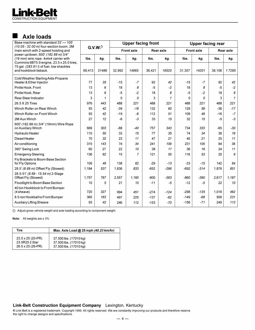
Base machine with standard 33' � 105'(10.05 - 32.00 m) four-section boom, 2Mmain winch with 2-speed hoisting and Front axle Rear axle Front axle Rear axlepower up/down, 600' (182.88 m) 3/4"(19 mm) wire rope, 4x4x4 carrier with lbs. kg. lbs. kg. lbs. kg. lbs. kg. lbs. kg.Cummins 6BT5.9 engine, 23.5 x 25.0 tires,75 gal. (283.91 l) of fuel, tow shacklesand hookblock tieback. 69,413 31486 32,992 14965 36,421 16520 31,307 14201 38,106 1 7285
Axle loadsUpper facing rear
G.V.W.1
Note: All weights are ± 3%
Tire
23.5 x 25 (20-PR)23.5R25 2 Star26.5 x 25 (26-PR)
Max. Axle Load @ 25 mph (40.23 km/hr)
37,500 lbs. (17010 kg)37,500 lbs. (17010 kg)37,500 lbs. (17010 kg)
-15 -7 92 42
18 8 -5 -2
-5 -2 18 8
0 0 3 1
488 221 488 221
129 59 -36 -17
109 49 -16 -7
32 15 -5 -3
734 333 -65 -30
74 34 36 16
45 21 25 11
231 105 84 38
36 16 24 11
116 53 20 9
-33 -15 142 64
-692 -314 1,876 851
-860 -390 2,617 1,187
-12 -5 22 10
-298 -135 1,018 462
-149 -68 509 231
-156 -71 249 113
Upper facing front
1 Adjust gross vehicle weight and axle loading according to component weight.
Link-Belt Construction Equipment Company Lexington, Kentucky® Link-Belt is a registered trademark. Copyright 1999. All rights reserved. We are constantly improving our products and therefore reservethe right to change designs and specifications.
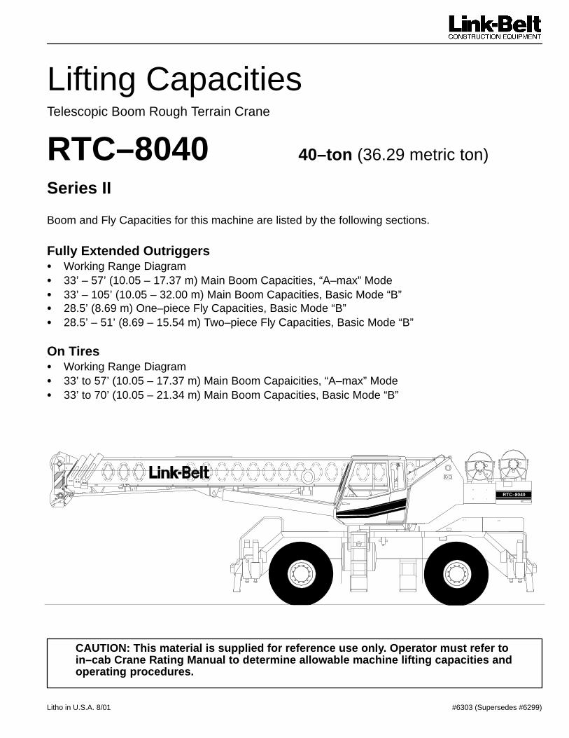
Boom and Fly Capacities for this machine are listed by the following sections.
Fully Extended Outriggers� Working Range Diagram� 33’ – 57’ (10.05 – 17.37 m) Main Boom Capacities, “A–max” Mode� 33’ – 105’ (10.05 – 32.00 m) Main Boom Capacities, Basic Mode “B”� 28.5’ (8.69 m) One–piece Fly Capacities, Basic Mode “B”� 28.5’ – 51’ (8.69 – 15.54 m) Two–piece Fly Capacities, Basic Mode “B”
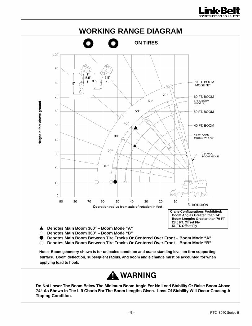
On Tires� Working Range Diagram� 33’ to 57’ (10.05 – 17.37 m) Main Boom Capaicities, “A–max” Mode� 33’ to 70’ (10.05 – 21.34 m) Main Boom Capacities, Basic Mode “B”
RTC–8040
CAUTION: This material is supplied for reference use only. Operator must refer toin–cab Crane Rating Manual to determine allowable machine lifting capacities andoperating procedures.
����RTC–8040 Series II
�������READ AND UNDERSTAND THE OPERATOR’S AND SAFETY MANUALS AND THE FOLLOWING INSTRUCTIONSAND RATED LIFTING CAPACITIES BEFORE OPERATING CRANE. OPERATION WHICH DOES NOT FOLLOWTHESE INSTRUCTIONS MAY RESULT IN AN ACCIDENT
OPERATING INSTRUCTIONSGENERAL:1. Rated lifting capacities in pounds as shown on lift charts
pertain to this crane as originally manufactured andnormally equipped. Modifications to the crane or use ofoptional equipment other than that specified can result ina reduction of capacity.
2. Construction equipment can be dangerous if improperlyoperated or maintained. Operation and maintenance ofthis crane must be in compliance with the information inthe Operator’s, Parts, and Safety Manuals supplied withthis crane. If these manuals are missing, orderreplacements through the distributor.
3. The operator and other personnel associated with thiscrane shall read and fully understand the latestapplicable American National Standards ASME B30.5safety standards for cranes.
4. The rated lifting capacities are based on crane standinglevel on firm supporting surface.
SET UP:1. The crane shall be leveled on a firm supporting surface.
Depending on the nature of the supporting surface, it maybe necessary to have structural supports under theoutrigger pontoons or tires to spread the load to a largerbearing surface.
2. When making lifts on outriggers, all tires must be free ofsupporting surface. All outrigger beams must beextended to the same length; fully retracted, intermediateextended, or fully extended.
3. When operating on tires over the side, do not exceed 75�maximum boom angle. Loss of backward stability willoccur causing a backward tipping condition.
4. When making lifts on tires, they must be inflated to therecommended pressure. (See Operation note 20 andTire Inflation.)
5. For required parts of line, see Wire Rope Capacity andWinch Performance.
6. Before setting up on intermediate outriggers, retractedoutriggers, or tires, refer to Working Range Diagrams andrated lifting capacities to determine allowable craneconfigurations.
OPERATION:1. Rated lifting capacities at rated radii shall not be
exceeded. Do not tip the crane to determine allowableloads. For concrete bucket operation, weight of bucketand load shall not exceed 80% of rated lifting capacities.For clamshell bucket operation, weight of bucket andbucket contents is restricted to a maximum weight of6,000 pounds or 80% of rated lifting capacity, whicheveris less. For magnet operation, weight of magnet and loadis restricted to a maximum weight of 6,000 pounds or80% of rated lifting capacity, whichever is less. Forclamshell and magnet operation, maximum boom lengthis restricted to 50 feet and the boom angle is restricted toa minimum of 35 degrees. Lifts with any fly erected areprohibited for both clam and magnet operation.
2. Rated lifting capacities shown on fully extended outriggersdo not exceed 85% of the tipping loads. Rated liftingcapacities shown on intermediate extended or fullyretracted outriggers are determined by the formula, ratedload = (tipping load – 0.1 X load factor) / 1.25. Rated liftingcapacities shown on tires do not exceed 75% of the tippingloads. Tipping loads are determined by SAE crane stabilitytest code J–765.
3. Rated lifting capacities in the shaded areas are based onstructural strength or hydraulic limitations and have beentested to meet minimum requirements of SAE J–1063cantilevered boom crane structures–method of test.Rated lifting capacities in the non–shaded areas are basedon stability ratings. Some capacities are limited by amaximum obtainable 78� boom angle.
4. Rated lifting capacities include the weight of hookball/block, slings, bucket, magnet and auxiliary liftingdevices. Their weights must be subtracted from the listedrated capacity to obtain the net load that can be lifted.Rated lifting capacities include the deduct for either flystowed on the base of the boom. For deducts of either flyerected, but not used, see Capacity Deductions ForAuxiliary Load Handling Equipment.
5. Rated lifting capacities are based on freely suspendedloads. No attempt shall be made to move a loadhorizontally on the ground in any direction.
6. Rated lifting capacities are for lift crane service only.7. Do not operate at radii or boom lengths (minimum or
maximum) where capacities are not listed. At thesepositions, the crane can tip or cause boom failure.
– 3 – RTC–8040 Series II
8. The maximum loads that can be telescoped are notdefinable because of variation in loadings and cranemaintenance, but it is permissible to attempt retraction andextension within the limits of the applicable load ratingchart.
9. For main boom capacities when either boom length orradius or both are between values listed, proceed asfollows:a. For boom lengths not listed, use rating for next longer
boom length or next shorter boom length, whicheveris smaller.
b. For load radii not listed, use rating for next larger radius.
10. The user shall operate at reduced ratings to allow foradverse job conditions, such as: soft or uneven ground,out of level conditions, wind, side loads, pendulum action,jerking or sudden stopping of loads, hazardousconditions, experience of personnel, traveling with loads,electrical wires, etc. Side load on boom or fly isdangerous and shall be avoided.
11. Rated lifting capacities do not account for wind onsuspended load or boom. Rated capacities and boomlength shall be appropriately reduced as wind velocityapproaches 20 mph.
12. When making lifts with auxiliary head machinery, theeffective length of the boom increases by 2 feet.
13. Power sections of boom must be extended in accordancewith boom mode “A” or “B”. In boom mode “B” all powersections must be extended or retracted equally.
14. The least stable rated working area depends on theconfiguration of the crane set up.
15. Rated lifting capacities are based on correct reeving.Deduction must be made for excessive reeving. Anyreeving over minimum required (see Wire RopeCapacity) is considered excessive and must beaccounted for when making lifts. Use Working RangeDiagram to estimate the extra feet of rope then deduct 1lb. for each extra foot of wire rope before attempting to lifta load.
16. The loaded boom angle combined with the boom lengthgive only an approximation of the operating radius. Theboom angle, before loading, should be greater to accountfor deflection. For main boom capacities, the loadedboom angle is for reference only. For fly capacities, theload radius is for reference only.
17. For fly capacities with main boom length less than 105 ft.and greater than 80 ft., the rated loads are determined bythe boom angle using the 105 ft. boom and fly chart. Forangles not shown use the next lower boom angle todetermine the rated capacity.
18. For fly capacites with main boom length less than 80 ft.the rated loads are determined by the boom angle onlyusing the 80 ft. boom and fly chart. For angles not shown,use the next lower boom angle to determine the ratedcapacity.
19. The 33 ft. boom length structural capacities are based onboom fully retracted. If the boom is not fully retracted, donot exceed capacities shown for the 40 ft. boom length.
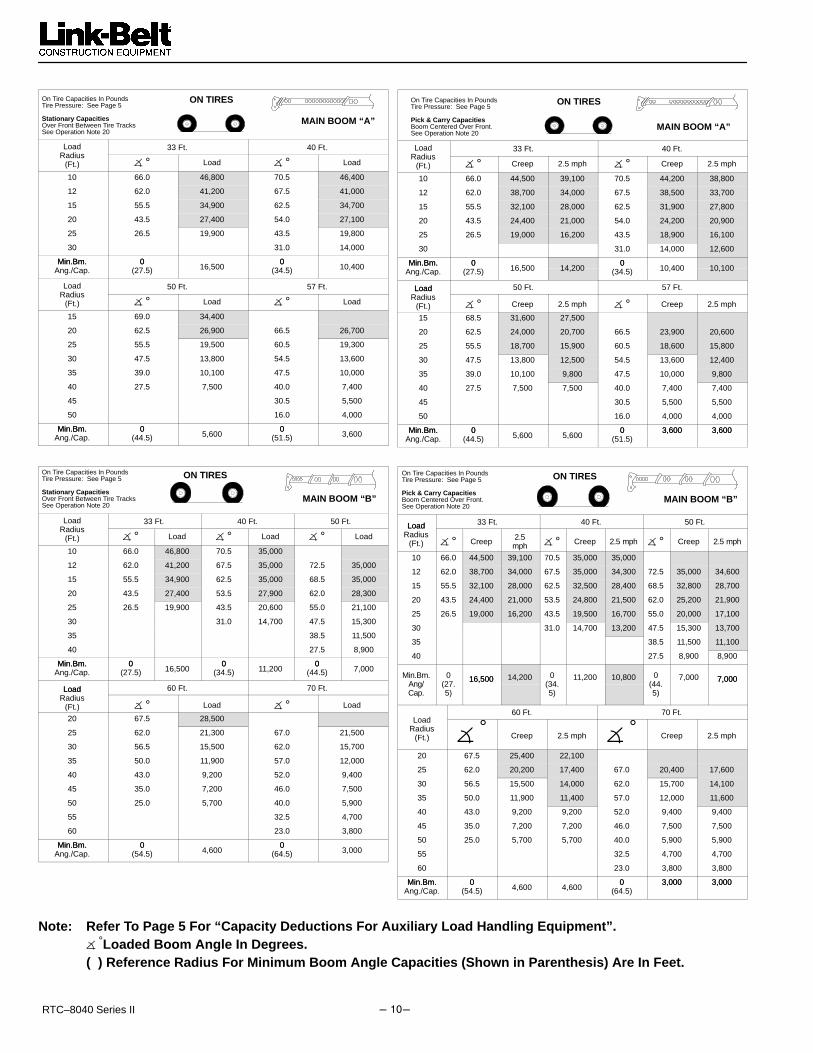
20. Rated lifting capacities on tires depend on tire capacity,condition of tires, and tire air pressure. On tire capacitiesrequire lifting from main boom head only on a smooth andlevel surface. Pick and carry operations are restricted tospeed of 2.5 mph and creep . The boom must becentered over the front of the crane with two–positiontravel swing lock engaged and the load must berestrained from swinging. Lifts with any fly erected ontires are prohibited. For correct tire pressure, see TireInflation.
DEFINITIONS:1. Load Radius: Horizontal distance from a projection of the
axis of rotation to the supporting surface, before loading,to the center of the vertical hoist line or tackle with loadapplied.
2. Loaded Boom Angle: � ° The angle between the boombase section and horizontal with freely suspended load atthe rated radius.
3. Working Area: Area measured in a circular arc about thecenter line of rotation as shown on the Working AreaDiagram.
4. Freely Suspended Load: Load hanging free with nodirect external force applied except by the hoist line.
5. Side Load: Horizontal side force applied to the lifted loadeither on the ground or in the air.
6. No Load Stability Limit: The radius or boom anglebeyond which it is not permitted to position the boombecause the crane can overturn without any load on thehook.
7. Load Factor: Load applied at the boom tip which givesthe same moment effect as the boom mass.
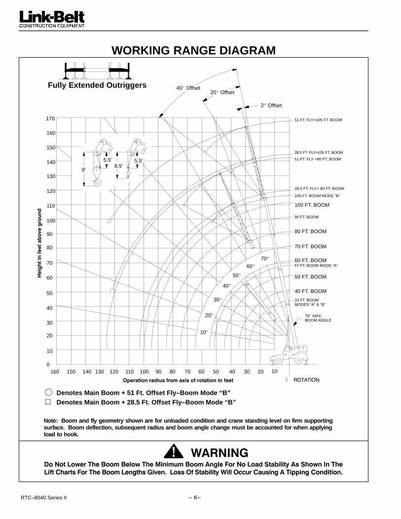
Note: Boom and fly geometry shown are for unloaded condition and crane standing level on firm supportingsurface. Boom deflection, subsequent radius and boom angle change must be accounted for when applyingload to hook.
')�������������%������*�%��������������������
0
10
20
30
40
50
60
80
90
100
110
120
������
70
130
140
9’
5.5’
20�
30�
40�
50�
60�
70�
10�
8.5’5.5’
150
160
� Denotes Main Boom + 51 Ft. Offset Fly–Boom Mode “B”� Denotes Main Boom + 28.5 Ft. Offset Fly–Boom Mode “B”
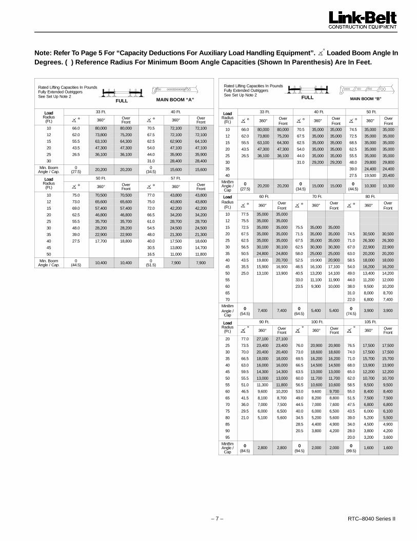
Note: Refer To Page 5 For “Capacity Deductions For Auxiliary Load Handling Equipment”. �� Loaded Boom Angle InDegrees. ( ) Reference Radius For Minimum Boom Angle Capacities (Shown In Parenthesis) Are In Feet.
FULL MAIN BOOM “A”
Rated Lifting Capacities In PoundsFully Extended OutriggersSee Set Up Note 2
Load 33 Ft. 40 Ft.LoadRadius
(Ft.) � ° 360° OverFront � ° 360° Over
Front
10 66.0 80,000 80,000 70.5 72,100 72,100
12 62.0 73,800 75,200 67.5 72,100 72,100
15 55.5 63,100 64,300 62.5 62,900 64,100
20 43.5 47,300 47,300 54.0 47,100 47,100
25 26.5 36,100 36,100 44.0 35,900 35,900
30 31.0 28,400 28,400
Min. BoomAngle / Cap.
0(27.5) 20,200 20,200 0
(34.5) 15,600 15,600
Load 50 Ft. 57 Ft.LoadRadius
(Ft.) � ° 360° OverFront � ° 360° Over
Front
10 75.0 70,500 70,500 77.0 43,800 43,800
12 73.0 65,600 65,600 75.0 43,800 43,800
15 69.0 57,400 57,400 72.0 42,200 42,200
20 62.5 46,800 46,800 66.5 34,200 34,200
25 55.5 35,700 35,700 61.0 28,700 28,700
30 48.0 28,200 28,200 54.5 24,500 24,500
35 39.0 22,900 22,900 48.0 21,300 21,300
40 27.5 17,700 18,800 40.0 17,500 18,600
45 30.5 13,800 14,700
50 16.5 11,000 11,800
Min. BoomAngle / Cap.
0(44.5) 10,400 10,400 0
(51.5) 7,900 7,900
MAIN BOOM “B”FULL
Rated Lifting Capacities In PoundsFully Extended OutriggersSee Set Up Note 2
Rated Lifting Capacities In PoundsFully Extended OutriggersSee Set Up Note 2
Load 2� Offset 20� Offset 40� OffsetLoadRadius
(Ft.) � ° 360° � ° 360° � ° 360°
25 77.0 13,800
30 74.5 12,800
35 72.0 11,800 76.0 8,700
40 69.0 11,000 73.0 8,100 77.0 6,100
45 66.0 10,200 70.0 7,500 74.0 5,800
50 63.0 9,600 67.0 7,100 71.0 5,600
55 60.0 8,900 64.0 6,700 67.5 5,400
60 57.0 8,200 61.0 6,300 64.0 5,200
65 53.5 7,600 57.5 6,000 60.5 5,100
70 50.0 7,100 54.0 5,700 57.0 5,000
75 46.5 6,600 50.0 5,500 52.5 4,900
80 42.0 6,000 46.0 5,300 48.0 4,800
85 37.5 5,300 41.5 5,100 43.0 4,800
90 32.0 4,600 36.0 4,800
95 26.0 4,000 29.0 4,200
100 17.0 3,500 19.0 3,600
Min. BoomAngle / Cap
0 1,700 0 1,800 0 1,900
28.5 Ft. Offset Fly
105 Ft. Main Boom
2� Offset
40� Offset
20�Offset
FULL
Rated Lifting Capacities In PoundsFully Extended OutriggersSee Set Up Note 2
Load 2� Offset 20� Offset 40� OffsetLoadRadius
(Ft.) � ° 360° � ° 360° � ° 360°
35 76.5 9,000
40 74.5 9,000 78.0* 7,900
45 72.5 8,700 76.0 7,500
50 70.0 7,900 73.5 7,100 76.5 5,600
55 67.5 7,200 71.0 6,600 74.0 5,500
60 65.5 6,600 69.0 6,100 71.5 5,300
65 63.0 6,100 66.5 5,600 69.5 5,200
70 60.5 5,600 64.0 5,200 66.5 4,900
75 57.5 5,100 61.0 4,900 64.0 4,600
80 55.0 4,600 58.5 4,600 61.0 4,400
85 52.0 4,100 55.5 4,300 58.0 4,100
90 49.0 3,600 52.5 3,800 55.0 3,900
95 45.5 3,300 49.0 3,400 51.5 3,500
100 42.5 2,900 45.5 3,000 47.5 3,100
105 38.5 2,600 41.5 2,700 43.0 2,700
110 34.5 2,300 37.5 2,400
115 30.0 2,000 32.5 2,100
120 24.0 1,700 26.5 1,800
Do Not Lower 28.5 Ft. Offset Fly In Working Position Below 17° Main Boom Angle UnlessMain Boom Length Is 102 Ft. Or Less, Since Loss Of Stability Will Occur Causing A TippingCondition.
�������
51 Ft. Offset Fly
80 Ft. Main Boom
2� Offset
40� Offset
20�Offset
FULL
Rated Lifting Capacities In PoundsFully Extended OutriggersSee Set Up Note 2
Load 2� Offset 20� Offset 40� OffsetLoadRadius
(Ft.) � ° 360° � ° 360° � ° 360°
35 76.0 7,400
40 74.0 6,700
45 71.5 6,100 78.0* 4,200
50 69.5 5,500 76.0 3,900
55 67.0 5,100 73.5 3,700
60 64.5 4,700 71.0 3,400 77.0 2,700
65 62.0 4,300 68.5 3,200 74.5 2,500
70 59.5 4,000 66.0 3,100 72.0 2,500
75 57.0 3,700 63.0 2,900 69.0 2,400
80 54.0 3,500 60.5 2,800 66.0 2,300
85 51.0 3,300 57.5 2,600 62.5 2,200
90 48.0 3,100 54.5 2,500 59.5 2,200
95 45.0 2,900 51.0 2,400 55.5 2,200
100 41.5 2,700 47.5 2,300 51.5 2,100
105 37.5 2,600 43.5 2,300 47.0 2,100
110 33.5 2,400 39.0 2,200 41.5 2,100
115 28.5 2,300 34.0 2,200
120 22.5 2,200 27.0 2,100
125 11.0 2,200
Min.BoomAngle/Cap.
0 900 0 900 0 1,100
51 Ft. Offset Fly
105 Ft. Main Boom
2� Offset
40� Offset
20�Offset
FULL
Rated Lifting Capacities In PoundsFully Extended OutriggersSee Set Up Note 2
Do Not Lower 51 Ft. Offset Fly In Working Position Below 34° Main Boom Angle UnlessMain Boom Length Is 92 Ft. Or Less, Since Loss Of Stability Will Occur Causing A TippingCondition.
�������
– 9 – RTC–8040 Series II
WORKING RANGE DIAGRAM
Denotes Main Boom 360° – Boom Mode “A”Denotes Main Boom 360° – Boom Mode “B”Denotes Main Boom Between Tire Tracks Or Centered Over Front – Boom Mode “A”Denotes Main Boom Between Tire Tracks Or Centered Over Front – Boom Mode “B”
Note: Boom geometry shown is for unloaded condition and crane standing level on firm supportingsurface. Boom deflection, subsequent radius, and boom angle change must be accounted for whenapplying load to hook.
Note: Refer To Page 5 For “Capacity Deductions For Auxiliary Load Handling Equipment”.�
°Loaded Boom Angle In Degrees.( ) Reference Radius For Minimum Boom Angle Capacities (Shown in Parenthesis) Are In Feet.
�����RTC–8040 Series II
Link–Belt Construction Equipment Company Lexington, Kentucky www.linkbelt.com� Link–Belt is a registered trademark. Copyright 2001. All rights reserved. We are constantly improving our products and therefore reserve the right to change designs and specifications.