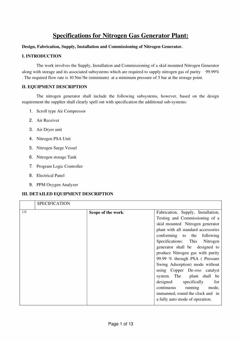
Specifications for Nitrogen Gas Generator Plant: Design, Fabrication, Supply, Installation and Commissioning of Nitrogen Generator. I. INTRODUCTION The work involves the Supply, Installation and Commissioning of a skid mounted Nitrogen Generator along with storage and its associated subsystems which are required to supply nitrogen gas of purity 99.99% . The required flow rate is 10 Nm 3 /hr (minimum) at a minimum pressure of 5 bar at the storage point. II. EQUIPMENT DESCRIPTION The nitrogen generator shall include the following subsystems, however, based on the design requirement the supplier shall clearly spell out with specification the additional sub-systems: 1. Scroll type Air Compressor 2. Air Receiver 3. Air Dryer unit 4. Nitrogen PSA Unit 5. Nitrogen Surge Vessel 6. Nitrogen storage Tank 7. Program Logic Controller 8. Electrical Panel 9. PPM Oxygen Analyzer III. DETAILED EQUIPMENT DESCRIPTION SPECIFICATION 1.0 Scope of the work: Fabrication, Supply, Installation, Testing and Commissioning of a skid mounted Nitrogen generator plant with all standard accessories conforming to the following Specifications: This Nitrogen generator shall be designed to produce Nitrogen gas with purity 99.99 % through PSA ( Pressure Swing Adsorption) mode without using Copper De-oxo catalyst system. The plant shall be designed specifically for continuous running mode, unmanned, round the clock and in a fully auto mode of operation. Page 1 of 13
Transcript
Specifications for Nitrogen Gas Generator Plant:Design, Fabrication, Supply, Installation and Commissioning of Nitrogen Generator.
I. INTRODUCTION
The work involves the Supply, Installation and Commissioning of a skid mounted Nitrogen Generator along with storage and its associated subsystems which are required to supply nitrogen gas of purity � 99.99% . The required flow rate is 10 Nm3/hr (minimum) at a minimum pressure of 5 bar at the storage point.
II. EQUIPMENT DESCRIPTION
The nitrogen generator shall include the following subsystems, however, based on the design requirement the supplier shall clearly spell out with specification the additional subsystems:
1. Scroll type Air Compressor
2. Air Receiver
3. Air Dryer unit
4. Nitrogen PSA Unit
5. Nitrogen Surge Vessel
6. Nitrogen storage Tank
7. Program Logic Controller
8. Electrical Panel
9. PPM Oxygen Analyzer
III. DETAILED EQUIPMENT DESCRIPTION
SPECIFICATION
1.0 Scope of the work: Fabrication, Supply, Installation, Testing and Commissioning of a skid mounted Nitrogen generator plant with all standard accessories conforming to the following Specifications: This Nitrogen generator shall be designed to produce Nitrogen gas with purity 99.99 % through PSA ( Pressure Swing Adsorption) mode without using Copper Deoxo catalyst system. The plant shall be designed specifically for continuous running mode, unmanned, round the clock and in a fully auto mode of operation.
Page 1 of 13
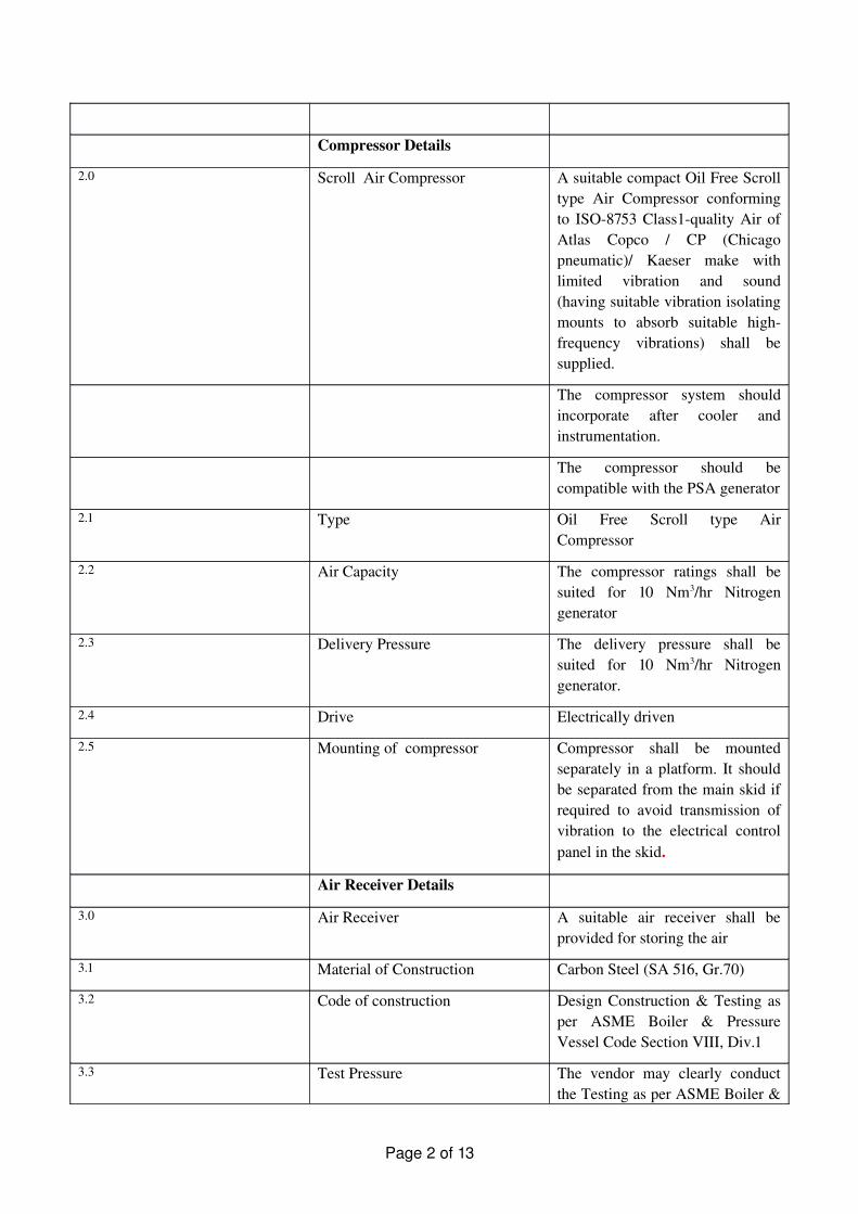
Compressor Details
2.0 Scroll Air Compressor A suitable compact Oil Free Scroll type Air Compressor conforming to ISO8753 Class1quality Air of Atlas Copco / CP (Chicago pneumatic)/ Kaeser make with limited vibration and sound (having suitable vibration isolating mounts to absorb suitable highfrequency vibrations) shall be supplied.
The compressor system should incorporate after cooler and instrumentation.
The compressor should be compatible with the PSA generator
2.1 Type Oil Free Scroll type Air Compressor
2.2 Air Capacity The compressor ratings shall be suited for 10 Nm3/hr Nitrogen generator
2.3 Delivery Pressure The delivery pressure shall be suited for 10 Nm3/hr Nitrogen generator.
2.4 Drive Electrically driven
2.5 Mounting of compressor Compressor shall be mounted separately in a platform. It should be separated from the main skid if required to avoid transmission of vibration to the electrical control panel in the skid.
Air Receiver Details
3.0 Air Receiver A suitable air receiver shall be provided for storing the air
3.1 Material of Construction Carbon Steel (SA 516, Gr.70)
3.2 Code of construction Design Construction & Testing as per ASME Boiler & Pressure Vessel Code Section VIII, Div.1
3.3 Test Pressure The vendor may clearly conduct the Testing as per ASME Boiler &
Page 2 of 13
Pressure Vessel Code Section VIII, Div.1
Air Dryer Details
4.0 Air Dryer Unit The filtered air may contain water vapour and should be purified further by Air Dryer.
4.1 Air Flow Capacity The air flow capacity of the air dryer unit shall be suited for 10 Nm3/hr Nitrogen generator.
4.2 Test Pressure The vendor may clearly conduct the Testing as per ASME Boiler & Pressure Vessel Code Section VIII, Div.1
PSA Unit Details
5.0 Nitrogen PSA Unit Nitrogen PSA unit should produce Nitrogen gas with suitable pressure by the pressure swing adsorption technique.
Nitrogen PSA unit should have two adsorbers filled with suitable carbon molecular sieves and interlinked by valves required for different functions of the PSA System. Both towers shall be interconnected by auto changeover valves which operates by PLC.
Dry nitrogen gas should be generated by the processes of adsorption, desorption (by depressurization) and repressurization.
5.1
Nitrogen Generation Capacity To be designed considering a final delivery of 10Nm3/hr
5.2 Number of PSA towers 2 Nos. (1 in operation mode & another in regeneration mode). Both towers shall be interconnected by auto changeover valves which operates by PLC.
5.3 Material of Construction Carbon Steel (SA 516, Gr.70)
5.4 Type of Vessel Vertical Vessel
5.5 PSA Valve operation PLC controlled
Page 3 of 13
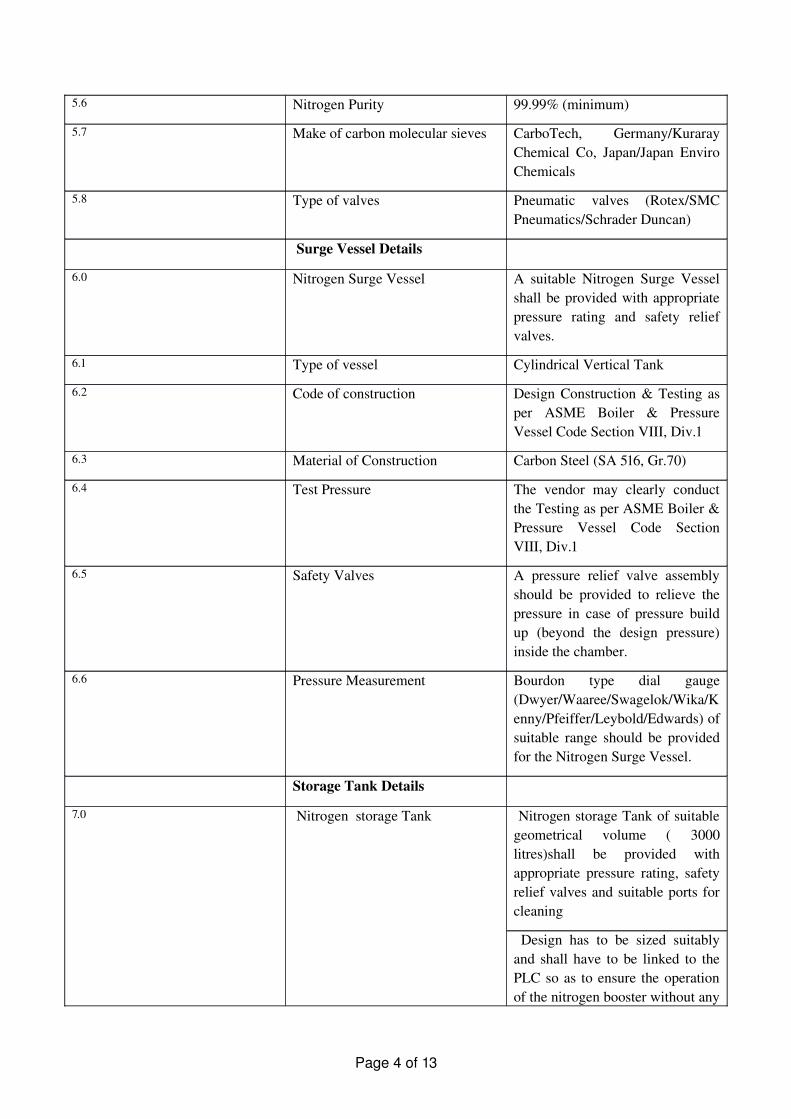
5.6 Nitrogen Purity 99.99% (minimum)
5.7 Make of carbon molecular sieves CarboTech, Germany/Kuraray Chemical Co, Japan/Japan Enviro Chemicals
5.8 Type of valves Pneumatic valves (Rotex/SMC Pneumatics/Schrader Duncan)
Surge Vessel Details
6.0
Nitrogen Surge Vessel
A suitable Nitrogen Surge Vessel shall be provided with appropriate pressure rating and safety relief valves.
6.1 Type of vessel Cylindrical Vertical Tank
6.2 Code of construction Design Construction & Testing as per ASME Boiler & Pressure Vessel Code Section VIII, Div.1
6.3 Material of Construction Carbon Steel (SA 516, Gr.70)
6.4 Test Pressure The vendor may clearly conduct the Testing as per ASME Boiler & Pressure Vessel Code Section VIII, Div.1
6.5 Safety Valves A pressure relief valve assembly should be provided to relieve the pressure in case of pressure build up (beyond the design pressure) inside the chamber.
6.6 Pressure Measurement Bourdon type dial gauge (Dwyer/Waaree/Swagelok/Wika/Kenny/Pfeiffer/Leybold/Edwards) of suitable range should be provided for the Nitrogen Surge Vessel.
Storage Tank Details
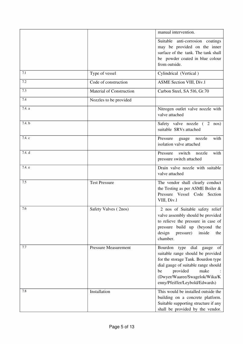
7.0 Nitrogen storage Tank Nitrogen storage Tank of suitable geometrical volume ( 3000 litres)shall be provided with appropriate pressure rating, safety relief valves and suitable ports for cleaning
Design has to be sized suitably and shall have to be linked to the PLC so as to ensure the operation of the nitrogen booster without any
Page 4 of 13
manual intervention.
Suitable anticorrosion coatings may be provided on the inner surface of the tank. The tank shall be powder coated in blue colour from outside.
7.1 Type of vessel Cylindrical (Vertical )
7.2 Code of construction ASME Section VIII, Div.1
7.3 Material of Construction Carbon Steel, SA 516, Gr.70
7.4 Nozzles to be provided
7.4. a Nitrogen outlet valve nozzle with valve attached
7.4. c Pressure guage nozzle with isolation valve attached
7.4. d Pressure switch nozzle with pressure switch attached
7.4. e Drain valve nozzle with suitable valve attached
7.5 Test Pressure The vendor shall clearly conduct the Testing as per ASME Boiler & Pressure Vessel Code Section VIII, Div.1
7.6 Safety Valves ( 2nos) 2 nos of Suitable safety relief valve assembly should be provided to relieve the pressure in case of pressure build up (beyond the design pressure) inside the chamber.
7.7 Pressure Measurement Bourdon type dial gauge of suitable range should be provided for the storage Tank. Bourdon type dial gauge of suitable range should be provided make : (Dwyer/Waaree/Swagelok/Wika/Kenny/Pfeiffer/Leybold/Edwards)
7.8 Installation This would be installed outside the building on a concrete platform. Suitable supporting structure if any shall be provided by the vendor.
Page 5 of 13
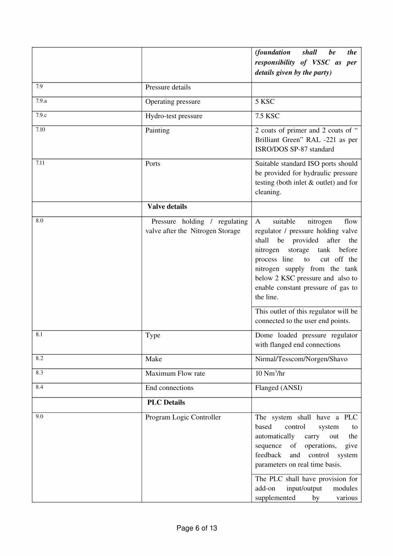
(foundation shall be the responsibility of VSSC as per details given by the party)
7.9 Pressure details
7.9.a Operating pressure 5 KSC
7.9.c Hydrotest pressure 7.5 KSC
7.10 Painting 2 coats of primer and 2 coats of “ Brilliant Green” RAL 221 as per ISRO/DOS SP87 standard
7.11 Ports Suitable standard ISO ports should be provided for hydraulic pressure testing (both inlet & outlet) and for cleaning.
Valve details
8.0
Pressure holding / regulating valve after the Nitrogen Storage
A suitable nitrogen flow regulator / pressure holding valve shall be provided after the nitrogen storage tank before process line to cut off the nitrogen supply from the tank below 2 KSC pressure and also to enable constant pressure of gas to the line.
This outlet of this regulator will be connected to the user end points.
8.1 Type Dome loaded pressure regulator with flanged end connections
8.2 Make Nirmal/Tesscom/Norgen/Shavo
8.3 Maximum Flow rate 10 Nm3/hr
8.4 End connections Flanged (ANSI)
PLC Details
9.0
Program Logic Controller
The system shall have a PLC based control system to automatically carry out the sequence of operations, give feedback and control system parameters on real time basis.
The PLC shall have provision for addon input/output modules supplemented by various
Page 6 of 13
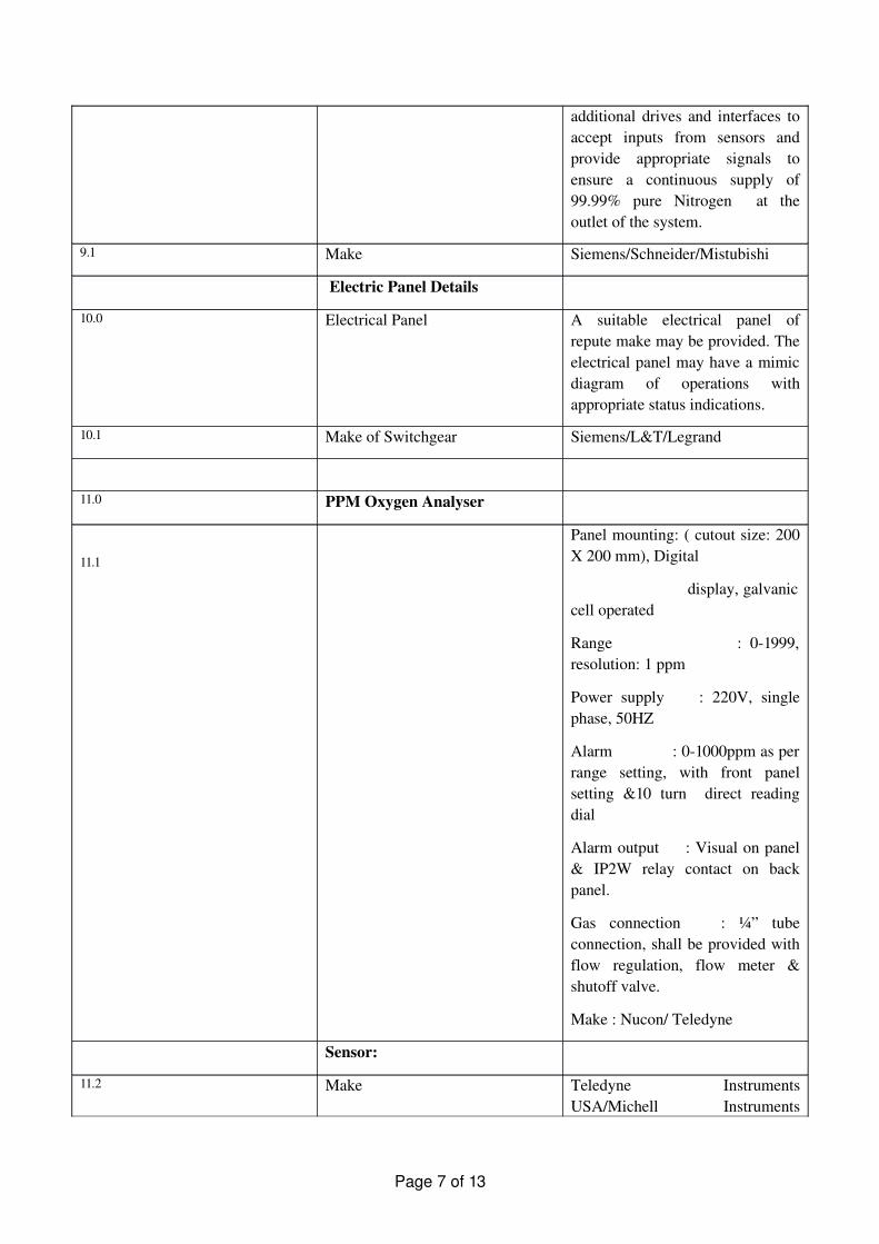
additional drives and interfaces to accept inputs from sensors and provide appropriate signals to ensure a continuous supply of 99.99% pure Nitrogen at the outlet of the system.
9.1 Make Siemens/Schneider/Mistubishi
Electric Panel Details
10.0 Electrical Panel A suitable electrical panel of repute make may be provided. The electrical panel may have a mimic diagram of operations with appropriate status indications.
10.1 Make of Switchgear Siemens/L&T/Legrand
11.0 PPM Oxygen Analyser
11.1
Panel mounting: ( cutout size: 200 X 200 mm), Digital
display, galvanic cell operated
Range : 01999, resolution: 1 ppm
Power supply : 220V, single phase, 50HZ
Alarm : 01000ppm as per range setting, with front panel setting &10 turn direct reading dial
Alarm output : Visual on panel & IP2W relay contact on back panel.
Gas connection : ¼” tube connection, shall be provided with flow regulation, flow meter & shutoff valve.
Make : Nucon/ Teledyne
Sensor:
11.2 Make Teledyne Instruments USA/Michell Instruments
Page 7 of 13
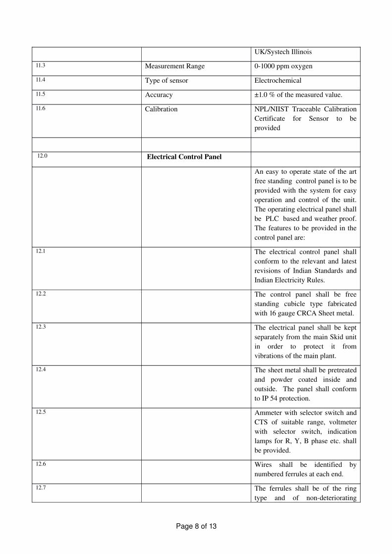
UK/Systech Illinois
11.3 Measurement Range 01000 ppm oxygen
11.4 Type of sensor Electrochemical
11.5 Accuracy ±1.0 % of the measured value.
11.6 Calibration NPL/NIIST Traceable Calibration Certificate for Sensor to be provided
12.0 Electrical Control Panel
An easy to operate state of the art free standing control panel is to be provided with the system for easy operation and control of the unit. The operating electrical panel shall be PLC based and weather proof. The features to be provided in the control panel are:
12.1 The electrical control panel shall conform to the relevant and latest revisions of Indian Standards and Indian Electricity Rules.
12.2 The control panel shall be free standing cubicle type fabricated with 16 gauge CRCA Sheet metal.
12.3 The electrical panel shall be kept separately from the main Skid unit in order to protect it from vibrations of the main plant.
12.4 The sheet metal shall be pretreated and powder coated inside and outside. The panel shall conform to IP 54 protection.
12.5 Ammeter with selector switch and CTS of suitable range, voltmeter with selector switch, indication lamps for R, Y, B phase etc. shall be provided.
12.6 Wires shall be identified by numbered ferrules at each end.
12.7 The ferrules shall be of the ring type and of nondeteriorating
Page 8 of 13
material. They shall be firmly located on each wire so as to prevent free movement.
12.8 Wiring for control circuit shall be made with suitable grade ISI marked, single core, multi stand copper conductor cable with proper termination with cable legs etc.
12.9 All incoming and outgoing cables to the panel shall be provided with appropriate cable glands.
12.10 All fuses provided shall be easily accessible.
12.11 The motor control panel shall consists of AC 23 duty switch fuse units of suitable capacity AC 3 duty starters with suitable overload relays, HRC fuse backup protection, and indication lamps etc . Party shall clearly specify the type of control switches and indications provided in the control panel
12.12 The panel shall be fitted with ventilation grills, vibration isolators and cooling fan.
12.13 All doors of the panel shall be earthed and have concealed hinges.
12.14 Provision for earthing at the two sides of the control panel shall be provided
12.15 Complete wiring for all power/control/sensor/circuits is between all motors/equipment/instruments and control panel shall be carried out with suitable size cables as per IS.
12
.16
The following controls shall be provided on the panel:
� Overload protection for compressor Pressure control
Page 9 of 13
with high/ low pressure switch
� Pressure indication with high/ low pressure switch
� Phase protection with single phase preventer for the compressor
� The compressor should get tripped in case of following
Storage vessel pressure reaches the set value
Insufficient cooling of the compressor
Failure of any phase in the electrical supply
Reverse rotation protection
High pressure unloading
12.17 Motor starter: Suitable push button starter switch (L &T or Siemens), with overload tripping facility shall be provided for operation. Only ISI certified starter switches shall be provided.
12.18 PLC shall be of Siemens/L&T /Legrand make, rugged type for trouble free operation.
12.19 Wiring: Electrical wiring from electrical panel to the compressor, controls and instruments. Complete interlocking and fault indication consisting of electrical switch gears including Siemens make isolator, fuses, contactor, thermal overload relay, single phase preventer etc. All the wiring shall confirm to approved standards.
12.20 Earthing: As per approved standard shall be provided for all
Page 10 of 13
the accessory units.
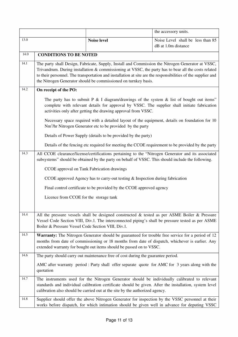
13.0 Noise level Noise Level shall be less than 85 dB at 1.0m distance
14.0 CONDITIONS TO BE NOTED
14.1 The party shall Design, Fabricate, Supply, Install and Commission the Nitrogen Generator at VSSC, Trivandrum. During installation & commissioning at VSSC, the party has to bear all the costs related to their personnel. The transportation and installation at site are the responsibilities of the supplier and the Nitrogen Generator should be commissioned on turnkey basis.
14.2 On receipt of the PO:
� The party has to submit P & I diagram/drawings of the system & list of bought out items” complete with relevant details for approval by VSSC. The supplier shall initiate fabrication activities only after getting the drawing approval from VSSC.
� Necessary space required with a detailed layout of the equipment, details on foundation for 10 Nm3/hr Nitrogen Generator etc to be provided by the party
� Details of Power Supply (details to be provided by the party)
� Details of the fencing etc required for meeting the CCOE requirement to be provided by the party
14.3 All CCOE clearance/license/certifications pertaining to the “Nitrogen Generator and its associated subsystems” should be obtained by the party on behalf of VSSC. This should include the following.
� CCOE approval on Tank Fabrication drawings
� CCOE approved Agency has to carryout testing & Inspection during fabrication
� Final control certificate to be provided by the CCOE approved agency
� Licence from CCOE for the storage tank
14.4 All the pressure vessels shall be designed constructed & tested as per ASME Boiler & Pressure Vessel Code Section VIII, Div.1. The interconnected piping’s shall be pressure tested as per ASME Boiler & Pressure Vessel Code Section VIII, Div.1.
14.5 Warranty: The Nitrogen Generator should be guaranteed for trouble free service for a period of 12 months from date of commissioning or 18 months from date of dispatch, whichever is earlier. Any extended warranty for bought out items should be passed on to VSSC.
14.6 The party should carry out maintenance free of cost during the guarantee period.
AMC after warranty period : Party shall offer separate quote for AMC for 3 years along with the quotation
14.7 The instruments used for the Nitrogen Generator should be individually calibrated to relevant standards and individual calibration certificate should be given. After the installation, system level calibration also should be carried out at the site by the authorized agency.
14.8 Supplier should offer the above Nitrogen Generator for inspection by the VSSC personnel at their works before dispatch, for which intimation should be given well in advance for deputing VSSC
Page 11 of 13
engineers to the party’s site.
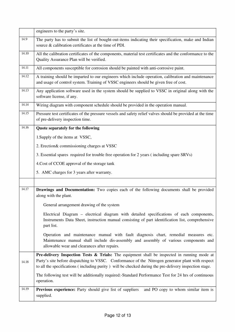
14.9 The party has to submit the list of boughtoutitems indicating their specification, make and Indian source & calibration certificates at the time of PDI.
14.10 All the calibration certificates of the components, material test certificates and the conformance to the Quality Assurance Plan will be verified.
14.11 All components susceptible for corrosion should be painted with anticorrosive paint.
14.12 A training should be imparted to our engineers which include operation, calibration and maintenance and usage of control system. Training of VSSC engineers should be given free of cost.
14.13 Any application software used in the system should be supplied to VSSC in original along with the software license, if any.
14.14 Wiring diagram with component schedule should be provided in the operation manual.
14.15 Pressure test certificates of the pressure vessels and safety relief valves should be provided at the time of predelivery inspection time.
14.16 Quote separately for the following
1.Supply of the items at VSSC,
2. Erection& commissioning charges at VSSC
3. Essential spares required for trouble free operation for 2 years ( including spare SRVs)
4.Cost of CCOE approval of the storage tank
5. AMC charges for 3 years after warranty.
14.17 Drawings and Documentation: Two copies each of the following documents shall be provided along with the plant.
� General arrangement drawing of the system
� Electrical Diagram – electrical diagram with detailed specifications of each components, Instruments Data Sheet, instruction manual consisting of part identification list, comprehensive part list.
� Operation and maintenance manual with fault diagnosis chart, remedial measures etc. Maintenance manual shall include disassembly and assembly of various components and allowable wear and clearances after repairs.
14.18
Predelivery Inspection Tests & Trials: The equipment shall be inspected in running mode at Party’s site before dispatching to VSSC. Conformance of the Nitrogen generator plant with respect to all the specifications ( including purity ) will be checked during the predelivery inspection stage.
The following test will be additionally required:Standard Performance Test for 24 hrs of continuous operation.
14.19 Previous experience: Party should give list of suppliers and PO copy to whom similar item is supplied.
Page 12 of 13
14.20
FLOOR AREA: The maximum floor area available for the installation & commissioning is 2.75 m wide X 3 meter length and 2.75 meter height. The system shall be designed maximum of this size. The system shall be compact type, designed accordingly. The drawing of the proposed plant shall be enclosed in the offer. The storage tank shall be kept outside building.
14.21 Drawing approval: After receiving the confirmed Purchase Order, party has to obtain drawing approval along with the P & ID of the system from VSSC before commencement of the fabrication .
14.22
The party should be ISO certified company and should provide valid ISO certificate.
14.23 Delivery schedule : Party should clearly specify in their tender the delivery schedule / time frame for the following
1. Supply of drawings for approval after the receipt of Purchase order
2. Readiness of the system for predelivery inspection from the date of drawing approval
3. Supply of the item at VSSC after the successful completion of the predelivery inspection trials at vendor site.
4. Erection , commissioning & demonstration at VSSC ,Trivandrum .
14.24 Party has to submit the duly filled compliance matrix along with the offer and shall bring out any deviations in detail, without fail.