24
1804 01T.EA319 HYDRAULIC CRAWLER CRANE 650TLX

1804 01T.EA319
HYDRAULIC CRAWLER CRANE
650TLX

2
Variation of The Attachment
VARIATION650TLX
Line Speed *
Front / Rear Winch
m/min
105
Third Winch (Optional) 105
Boom Raising Speed* sec/degree 52 / 0 to 78.0Swing Speed min-1 (rpm) 4.5Travel Speed High / Low * km/h 1.7 / 1.2Gradeability % (Degree) 30 (17)
Engine Model ISUZU 6HK1 (Stage Ⅲ B, Int.Tier 4)
Engine Rated Output Power kW/min-1
(ps/rpm)210 / 1900
(285 / 1900)
Note : Speeds marked with "*" may vary depending on load applied.
Boom Length m 10 to 30.1Ground ContactPressure kPa (kgf/cm²)
92.4 (0.94)(with 65 t hook)
Overall OperatingWeight t
70.9(with 65 t hook)
Crane Specification (Boom Longest Length)
3
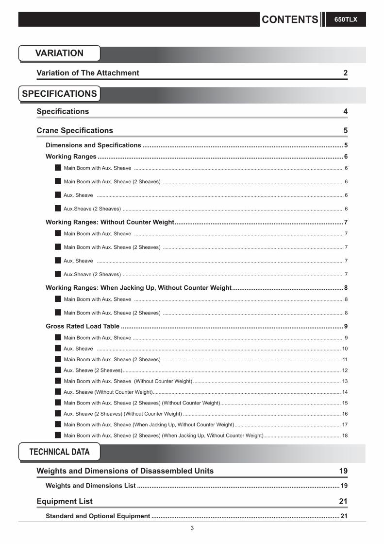
Variation of The Attachment 2
Specifications 4
Crane Specifications 5
Dimensions and Specifications ................................................................................................................5
Working Ranges .........................................................................................................................................6 Main Boom with Aux. Sheave .................................................................................................................................................. 6
Main Boom with Aux. Sheave (2 Sheaves) .............................................................................................................................. 6
Aux. Sheave ............................................................................................................................................................................ 6
Aux.Sheave (2 Sheaves) .......................................................................................................................................................... 6
Working Ranges: Without Counter Weight ..............................................................................................7 Main Boom with Aux. Sheave .................................................................................................................................................. 7
Main Boom with Aux. Sheave (2 Sheaves) .............................................................................................................................. 7
Aux. Sheave ............................................................................................................................................................................ 7
Aux.Sheave (2 Sheaves) .......................................................................................................................................................... 7
Working Ranges: When Jacking Up, Without Counter Weight ..............................................................8 Main Boom with Aux. Sheave .................................................................................................................................................. 8
Main Boom with Aux. Sheave (2 Sheaves) .............................................................................................................................. 8
Gross Rated Load Table ............................................................................................................................9 Main Boom with Aux. Sheave ................................................................................................................................................... 9
Aux. Sheave .......................................................................................................................................................................... 10
Main Boom with Aux. Sheave (2 Sheaves) .............................................................................................................................11
Aux. Sheave (2 Sheaves) ........................................................................................................................................................ 12
Main Boom with Aux. Sheave (Without Counter Weight) ....................................................................................................... 13
Aux. Sheave (Without Counter Weight) ................................................................................................................................... 14
Main Boom with Aux. Sheave (2 Sheaves) (Without Counter Weight) .................................................................................... 15
Aux. Sheave (2 Sheaves) (Without Counter Weight) .............................................................................................................. 16
Main Boom with Aux. Sheave (When Jacking Up, Without Counter Weight) .......................................................................... 17
Main Boom with Aux. Sheave (2 Sheaves) (When Jacking Up, Without Counter Weight)...................................................... 18
VARIATION
SPECIFICATIONS
CONTENTS 650TLX
TECHNICAL DATA
Weights and Dimensions of Disassembled Units 19
Weights and Dimensions List .................................................................................................................19
Equipment List 21
Standard and Optional Equipment .........................................................................................................21

4
SpecificationsEngine
Control
Hydraulic System
Front and Rear WinchWinch Front RearRope Diameter 22.4mm 22.4mm
Rope Winding Length
Standard 175 m 76 m for Aux. sheaveMax. (In non-work) 260 m 260 m
Line Pull Rated 69 kN 69 kN
Standard Equipment Free fall winch with brake controled by pedal operation.
Winch
Consisted of hydraulic motor with reduction gear and multi-disc brakes and a swing bearing which has inner tooth.
Swing System
Counter Weight(Without self assembly unit)
Total Weight 14.0 ton3.0 ton Base Weight 1 piece2.7 ton Right Weight 2 pieces2.8 ton Left Weight 2 pieces
Counter Weight
Welded steel construction with crawler sideframe extend-retract cylinders.
Carbody
Frame Welded steel box construction, and can be retracted.
Shoe Cast iron 760 mm width shoe each side.Upper Roller 2 pieces each side.
Lower Roller10 pieces each side.Forging heat treated steel with double flange type.2 plane bearing with floating seal for lifetime lubrication.
Travel Device
1 piece each side.Hydraulic travel device (Hydrayulic motor and reducer)Travel speed(Gradability : 30%)
High : 1.7 km/hLow : 1.2 km/h
Crawler Sideframe
Third Winch (Optional)Rope Diameter 22.4mm
Rope Winding Length
Standard 170 mMax. (In non-work)
260 m (With free fall)280 m (Without free fall)
Line Pull Rated 69 kNNotes Winch without free fall or free fall winch with
brake controled by pedal operation.
Counter Weight(With self assembly unit)
Total Weight 13.6 ton2.6 ton Base Weight 1 piece2.7 ton Right Weight 2 pieces2.8 ton Left Weight 2 pieces
Model ISUZU 6HK1
Type 4-cycle, Water-cooled, Direct injection, Turbo-charged, Diesel engine
Displacement 7.79 litersRated Output 210 kW / 1,900 min-1 (285 ps / 1,900 rpm)Fuel Tank Capacity 400 litersNotes Engine meets Stage Ⅲ B / Int. Tier 4 of engine exhaust gas
emission regulations in USA, Europe, and Japan. Engine rated horsepower is based on international rating formula that includes engine alternator and without fan.
Control System
Main actuators are actuated by main hydraulic system controlled with pilot hydraulic system. Safety devices are securely operated by combined various electronic control with hydraulic system. Working speed can be precisely controlled according to control lever stroke and control dials depending on work.
Control Levers Designed and positioned based on ergonomics. Arm-chair lever type is standard.
Display Panel Design 8 inches size. Located to check work state easily without disturbing the view of the operator.
Hydraulic Oil Tank Capacity 800 liters
Hydraulic Pump Capacity
Max. 31.4 MPa
P1 266 L / min Front winch, Third winch, Auger, Boom telescoping and Travel
P2 266 L / min Rear winch, Auger, Boom hoist and Travel
P3 152 L / minSwing, Jack, Crawler sideframe extend-retract and External hydraulic power equipment B
P4 38 L / minPilot control, External hydraulic power equipment A and others.
P5 38 L / minP6 38 L / minP7 30 L / min
Specifications
SPECIFICATIONS650TLX
5
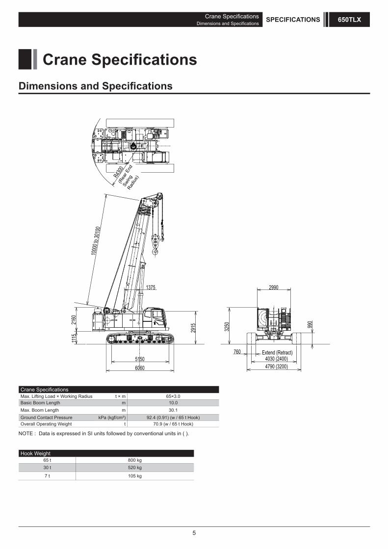
Dimensions and Specifications
Crane SpecificationsMax. Lifting Load × Working Radius t × m 65×3.0Basic Boom Length m 10.0Max. Boom Length m 30.1Ground Contact Pressure kPa (kgf/cm²) 92.4 (0.91) (w / 65 t Hook)Overall Operating Weight t 70.9 (w / 65 t Hook)
Hook Weight65 t 800 kg30 t 520 kg
7 t 105 kg
Crane Specifications
NOTE : Data is expressed in SI units followed by conventional units in ( ).
6060
2160
1000
0 to 3
0100
R4300
2915
5150
1375
1115
7604030 (2400)4790 (3200)
2990
3250
Extend (Retract)
(Rea
r End
Sw
ing
Radiu
s)
990
Crane SpecificationsDimensions and Specifications
SPECIFICATIONS 650TLX

6
Working Ranges
Main Boom with Aux. Sheave
Maximum Boom Angle
Minimum Boom Angle (31.5°)
36
Working Radius (m)
30 t Hook
Minimum Boom Angle (34.4°)
Minimum Boom Angle (32.1°)
Height A
bove Ground
(m)
Aux. Sheave
Crane SpecificationsWorking Ranges
SPECIFICATIONS650TLX
65 t Hook
30
24
12
18
6
6 12 18 24 30
30.1m
10.0m
23.4m
16.7m30°
4.3m
4.0m
7 t Hook
3.9m
Maximum Boom Angle
80°
2.91
5m
1.375m
Minimum Boom Angle (34.4°)
Minimum Boom Angle (36.5°)
Minimum Boom Angle (40.1°)
Minimum Boom Angle (41.8°)
Working Radius (m)
80°
30.1m
23.4m
16.7m18
10.0m
12
6
2.91
5m
1.375m6 12 18 24 30
24
30
36
30°
Main Boom with Aux. Sheave (2 Sheaves)
Maximum Boom Angle
Minimum Boom Angle (31.5°)
36
Working Radius (m)
30 t Hook
Minimum Boom Angle (34.4°)
Minimum Boom Angle (32.1°)
65 t Hook
30
24
12
18
6
6 12 18 24 30
30.1m
10.0m
23.4m
16.7m30°
80°
2.91
5m
1.375m
4.3m
4.0m
Aux.Sheave (2 Sheaves)
7 t Hook
3.9m
Maximum Boom Angle
Minimum Boom Angle (34.4°)
Minimum Boom Angle (36.5°)
Minimum Boom Angle (40.1°)
Minimum Boom Angle (41.8°)
Working Radius (m)
80°
30.1m
23.4m
16.7m
18
10.0m
12
6
2.91
5m
1.375m 6 12 18 24 30
24
30
36
30°
Height A
bove Ground
(m)
Height A
bove Ground
(m)
Height A
bove Ground
(m)
Minimum Boom Angle (30.9°)
Minimum Boom Angle (30.9°)

7
Crane SpecificationsWorking Ranges: Without Counter Weight
SPECIFICATIONS 650TLX
Main Boom with Aux. Sheave Aux. Sheave
Working Ranges: Without Counter Weight
Maximum Boom Angle
30°
80°
30 t Hook65 t Hook
4.3m
4.0m
24
18
12
6
2.91
5m
1.375mWorking Radius (m)
6 12 18
Minimum Boom Angle (31.5°)
Minimum Boom Angle (34.4°)
10.0m
16.7m
7 t Hook
30°
Maximum Boom Angle
24
18
12
6
2.91
5m
1.375m
3.9m
Minimum Boom Angle (40.1°)
Minimum Boom Angle (41.8°)
6 12 18
Working Radius (m)
16.7m
10.0m
80°
Main Boom with Aux. Sheave (2 Sheaves)
Maximum Boom Angle
30°
80°
30 t Hook65 t Hook
4.3m
4.0m
24
18
12
6
2.91
5m
1.375m
Working Radius (m)
6 12 18
Minimum Boom Angle (31.5°)
Minimum Boom Angle (34.4°)
10.0m
16.7m
Aux.Sheave (2 Sheaves)
7 t Hook
Maximum Boom Angle
24
18
12
6
2.91
5m
1.375m
3.9m
Minimum Boom Angle (40.1°)
Minimum Boom Angle (41.8°)
6 12 18
Working Radius (m)
16.7m
10.0m
80°
Height A
bove Ground
(m)H
eight Above G
round(m)
Height A
bove Ground
(m)
Height A
bove Ground
(m)
8
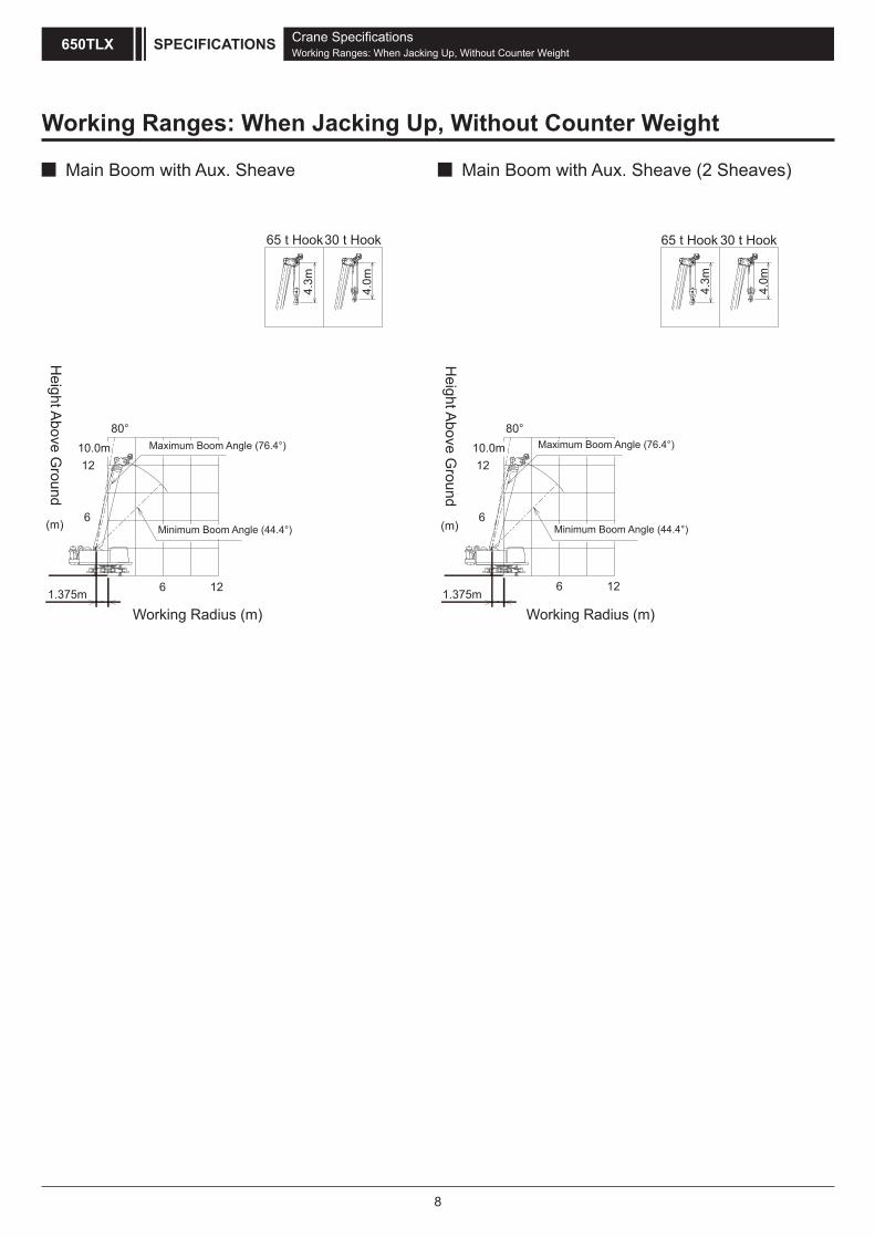
Working Ranges: When Jacking Up, Without Counter Weight
Main Boom with Aux. Sheave
Working Radius (m)
30 t Hook
Minimum Boom Angle (44.4°)
65 t Hook
4.3m
4.0m
80°
1.375m 6 12
12
6
10.0m Maximum Boom Angle (76.4°)
Main Boom with Aux. Sheave (2 Sheaves)
Working Radius (m)
30 t Hook
Minimum Boom Angle (44.4°)
65 t Hook
4.3m
4.0m
80°
1.375m6 12
12
6
10.0m Maximum Boom Angle (76.4°)
Crane SpecificationsWorking Ranges: When Jacking Up, Without Counter Weight
SPECIFICATIONS650TLX
Height A
bove Ground
(m)
Height A
bove Ground
(m)

9
Crane SpecificationsGross Rated Load Table
SPECIFICATIONS 650TLX
Gross Rated Load Table
Main Boom with Aux. Sheave
Unit: ton
WorkingRadius(m) 10.0
2 65.0
2.5 65.0
3 65.0
3.5 55.0
4 48.0
4.5 41.5
5 37.0
5.5 34.0
6 32.5
7 26.3
8 7.7m x
9 22.5t
10
12
14
16
18
20
22
24
26
28
1. The maximum rated loads as above are the value of the stationary loads on a firm and level surface,
are not more than 78% of minimum tipping loads, and 1.15 or more as specified in mobile crane structure specifications.
2. To calculate the maximum load that can actually be lifted, deduct mass of all lifting accessories,
such as a hook, from figures shown above.
3. Capacities surrounded by bold lines are based on factors other than those which would cause a tipping condition.
4. Working radius is the horizontal distance from the slewing center to the center of gravity of a lifted load.
5. 14 ton counter weight is required for all capacities on this chart.
6. Correlation between the number of reeved lines, maximum rated loads, hook mass are shown in the table below.
Hook Capacity Hook Mass(ton) 10 falls 8 falls 6 falls 5 falls 4 falls 3 falls 2 falls 1 fall
65t 0.80 65 56 42 - 28 - 14 -
30t 0.52 - 30 28 21 14 -
7t 0.11 -
-
-
-
- - - - - 7
Maximum Rated Loads (ton)
16.7 23.4 30.1
Boom Length (m)
2
2.5
32.0
32.0
32.0
32.0
30.5
28.8
26.5
23.0
19.7
16.7
14.3
10.5
13.0m x
9.1t
26.0
26.0
26.0
25.0
23.0
20.2
17.8
15.5
13.5
10.3
7.9
6.0
4.6
19.0m x
4.1t
4
4.5
5
5.5
3
3.5
6
7
8
9
10
12
14
16
18
20
22
24
4.1
26
28
16.0
16.0
16.0
16.0
15.0
13.4
3.1
2.3
25.0m x
2.0t
12.0
9.9
8.0
6.5
5.2
WorkingRadius(m)

10
Aux. Sheave
Crane SpecificationsGross Rated Load Table
SPECIFICATIONS650TLX
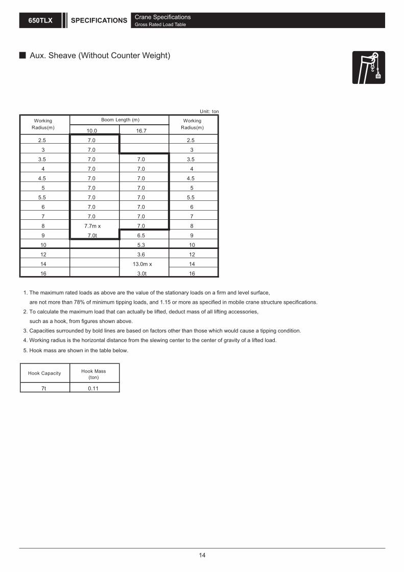
10.0 16.7 23.4 30.1
2.5 7.0 2.5
3 7.0 3
3.5 7.0 7.0 3.5
4 7.0 7.0 4
4.5 7.0 7.0 7.0 4.5
5 7.0 7.0 7.0 5
5.5 7.0 7.0 7.0 7.0 5.5
6 7.0 7.0 7.0 7.0 6
7 7.0 7.0 7.0 7.0 7
8 7.7m x 7.0 7.0 7.0 8
9 7.0t 7.0 7.0 7.0 9
10 7.0 7.0 7.0 10
12 7.0 7.0 7.0 12
14 13.0m x 7.0 7.0 14
16 7.0t 6.0 6.5 16
18 4.6 5.2 18
20 19.0m x 4.1 20
22 4.1t 3.1 22
24 2.3 24
26 25.0m x 26
28 2.0t 28
7t 0.11
WorkingRadius(m)
Boom Length (m) WorkingRadius(m)
Unit: ton
Hook Capacity Hook Mass(ton)
1. The maximum rated loads as above are the value of the stationary loads on a firm and level surface,
are not more than 78% of minimum tipping loads, and 1.15 or more as specified in mobile crane structure specifications.
2. To calculate the maximum load that can actually be lifted, deduct mass of all lifting accessories,
such as a hook, from figures shown above.
3. Capacities surrounded by bold lines are based on factors other than those which would cause a tipping condition.
4. Working radius is the horizontal distance from the slewing center to the center of gravity of a lifted load.
5. 14 ton counter weight is required for all capacities on this chart.
6. Hook mass are shown in the table below.

11
Crane SpecificationsGross Rated Load Table
SPECIFICATIONS 650TLX
10.0
2 65.0
2.5 65.0
3 65.0
3.5 54.9
4 47.9
4.5 41.4
5 36.9
5.5 33.9
6 32.4
7 26.2
8 7.7m x
9 22.4t
10
12
14
16
18
20
22
24
26
28
3.0
2.2
25.0m x
1.9t
11.9
9.8
7.9
6.4
5.1
4.0
26
28
15.9
15.9
15.9
15.9
14.9
13.3
14
16
18
20
22
24
6
7
8
9
10
12
4
4.5
5
5.5
3
3.5
4.5
19.0m x
4.0t
17.7
15.4
13.4
10.2
7.8
5.9
25.9
25.9
25.9
24.9
22.9
20.1
19.6
16.6
14.2
10.4
13.0m x
9.0t
31.9
31.9
30.4
28.7
26.4
22.9
31.9
31.9
2
2.5
16.7 23.4 30.1
Unit: ton
WorkingRadius(m)
Boom Length (m) WorkingRadius(m)
1. The maximum rated loads as above are the value of the stationary loads on a firm and level surface,
are not more than 78% of minimum tipping loads, and 1.15 or more as specified in mobile crane structure specifications.
2. To calculate the maximum load that can actually be lifted, deduct mass of all lifting accessories,
such as a hook, from figures shown above.
3. Capacities surrounded by bold lines are based on factors other than those which would cause a tipping condition.
4. Working radius is the horizontal distance from the slewing center to the center of gravity of a lifted load.
5. 14 ton counter weight is required for all capacities on this chart.
6. Correlation between the number of reeved lines, maximum rated loads, hook mass are shown in the table below.
Hook Capacity Hook Mass(ton) 10 falls 8 falls 6 falls 5 falls 4 falls 3 falls 2 falls 1 fall
65t 0.80 65 56 42 - 28 - 14 -
30t 0.52 - 30 28 21 14 -
7t 0.11 -
-
-
-
- - - - - 7
Maximum Rated Loads (ton)
Main Boom with Aux. Sheave (2 Sheaves)

12
Crane SpecificationsGross Rated Load Table
SPECIFICATIONS650TLX
10.0 16.7 23.4 30.1
2.5 7.0 2.5
3 7.0 3
3.5 7.0 7.0 3.5
4 7.0 7.0 4
4.5 7.0 7.0 7.0 4.5
5 7.0 7.0 7.0 5
5.5 7.0 7.0 7.0 7.0 5.5
6 7.0 7.0 7.0 7.0 6
7 7.0 7.0 7.0 7.0 7
8 7.7m x 7.0 7.0 7.0 8
9 7.0t 7.0 7.0 7.0 9
10 7.0 7.0 7.0 10
12 7.0 7.0 7.0 12
14 13.0m x 7.0 7.0 14
16 7.0t 5.9 6.4 16
18 4.5 5.1 18
20 19.0m x 4.0 20
22 4.0t 3.0 22
24 2.2 24
26 25.0m x 26
28 1.9t 28
7t 0.11
Hook Capacity Hook Mass(ton)
1. The maximum rated loads as above are the value of the stationary loads on a firm and level surface,
are not more than 78% of minimum tipping loads, and 1.15 or more as specified in mobile crane structure specifications.
2. To calculate the maximum load that can actually be lifted, deduct mass of all lifting accessories,
such as a hook, from figures shown above.
3. Capacities surrounded by bold lines are based on factors other than those which would cause a tipping condition.
4. Working radius is the horizontal distance from the slewing center to the center of gravity of a lifted load.
5. 14 ton counter weight is required for all capacities on this chart.
6. Hook mass are shown in the table below.
WorkingRadius(m)
Boom Length (m) WorkingRadius(m)
Unit: ton
Aux. Sheave (2 Sheaves)

13
Main Boom with Aux. Sheave (Without Counter Weight)
Crane SpecificationsGross Rated Load Table
SPECIFICATIONS 650TLX
10.0
2 26.0
2.5 26.0
3 26.0
3.5 26.0
4 26.0
4.5 26.0
5 21.8
5.5 18.0
6 15.3
7 11.4
8 7.7m x
9 9.5t
10
12
14
16
8
9
10
12
14
16
4
4.5
5
5.5
6
7
8.2
6.5
5.3
3.6
13.0m x
3.0t
19.0
19.0
19.0
16.5
14.0
10.5
19.0
19.0
2
2.5
3
3.5
16.7Working
Radius(m)Boom Length (m) Working
Radius(m)
Unit: ton
1. The maximum rated loads as above are the value of the stationary loads on a firm and level surface,
are not more than 78% of minimum tipping loads, and 1.15 or more as specified in mobile crane structure specifications.
2. To calculate the maximum load that can actually be lifted, deduct mass of all lifting accessories,
such as a hook, from figures shown above.
3. Working radius is the horizontal distance from the slewing center to the center of gravity of a lifted load.
4. Correlation between the number of reeved lines, maximum rated loads, hook mass are shown in the table below.
Hook Capacity Hook Mass(ton) 4 falls 3 falls 2 falls 1 fall
65t 0.80 28 - 14 -
30t 0.52 28 21 14 -
7t 0.11 - - - 7
Maximum Rated Loads (ton)
14
Crane SpecificationsGross Rated Load Table
SPECIFICATIONS650TLX
10.0 16.7
2.5 7.0 2.5
3 7.0 3
3.5 7.0 7.0 3.5
4 7.0 7.0 4
4.5 7.0 7.0 4.5
5 7.0 7.0 5
5.5 7.0 7.0 5.5
6 7.0 7.0 6
7 7.0 7.0 7
8 7.7m x 7.0 8
9 7.0t 6.5 9
10 5.3 10
12 3.6 12
14 13.0m x 14
16 3.0t 16
7t 0.11
Hook Capacity Hook Mass(ton)
1. The maximum rated loads as above are the value of the stationary loads on a firm and level surface,
are not more than 78% of minimum tipping loads, and 1.15 or more as specified in mobile crane structure specifications.
2. To calculate the maximum load that can actually be lifted, deduct mass of all lifting accessories,
such as a hook, from figures shown above.
3. Capacities surrounded by bold lines are based on factors other than those which would cause a tipping condition.
4. Working radius is the horizontal distance from the slewing center to the center of gravity of a lifted load.
5. Hook mass are shown in the table below.
WorkingRadius(m)
Boom Length (m) WorkingRadius(m)
Unit: ton
Aux. Sheave (Without Counter Weight)
15
Crane SpecificationsGross Rated Load Table
SPECIFICATIONS 650TLX
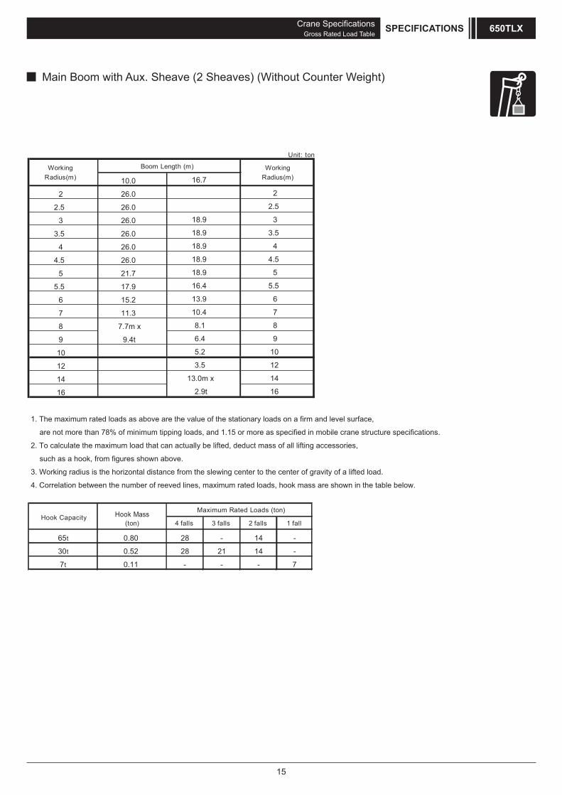
Main Boom with Aux. Sheave (2 Sheaves) (Without Counter Weight)
10.0
2 26.0
2.5 26.0
3 26.0
3.5 26.0
4 26.0
4.5 26.0
5 21.7
5.5 17.9
6 15.2
7 11.3
8 7.7m x
9 9.4t
10
12
14
16
8
9
10
12
14
16
4
4.5
5
5.5
6
7
8.1
6.4
5.2
3.5
13.0m x
2.9t
18.9
18.9
18.9
16.4
13.9
10.4
18.9
18.9
2
2.5
3
3.5
16.7
1. The maximum rated loads as above are the value of the stationary loads on a firm and level surface,
are not more than 78% of minimum tipping loads, and 1.15 or more as specified in mobile crane structure specifications.
2. To calculate the maximum load that can actually be lifted, deduct mass of all lifting accessories,
such as a hook, from figures shown above.
3. Working radius is the horizontal distance from the slewing center to the center of gravity of a lifted load.
4. Correlation between the number of reeved lines, maximum rated loads, hook mass are shown in the table below.
Hook Capacity Hook Mass(ton) 4 falls 3 falls 2 falls 1 fall
65t 0.80 28 - 14 -
30t 0.52 28 21 14 -
7t 0.11 - - - 7
Maximum Rated Loads (ton)
WorkingRadius(m)
Boom Length (m) WorkingRadius(m)
Unit: ton

16
Crane SpecificationsGross Rated Load Table
SPECIFICATIONS650TLX
10.0 16.7
2.5 7.0 2.5
3 7.0 3
3.5 7.0 7.0 3.5
4 7.0 7.0 4
4.5 7.0 7.0 4.5
5 7.0 7.0 5
5.5 7.0 7.0 5.5
6 7.0 7.0 6
7 7.0 7.0 7
8 7.7m x 7.0 8
9 7.0t 6.4 9
10 5.2 10
12 3.5 12
14 13.0m x 14
16 2.9t 16
7t 0.11
Hook Capacity Hook Mass(ton)
1. The maximum rated loads as above are the value of the stationary loads on a firm and level surface,
are not more than 78% of minimum tipping loads, and 1.15 or more as specified in mobile crane structure specifications.
2. To calculate the maximum load that can actually be lifted, deduct mass of all lifting accessories,
such as a hook, from figures shown above.
3. Capacities surrounded by bold lines are based on factors other than those which would cause a tipping condition.
4. Working radius is the horizontal distance from the slewing center to the center of gravity of a lifted load.
5. Hook mass are shown in the table below.
WorkingRadius(m)
Boom Length (m) WorkingRadius(m)
Unit: ton
Aux. Sheave (2 Sheaves) (Without Counter Weight)
17
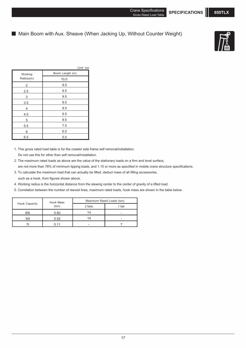
2
2.5
3
3.5
4
4.5
5
5.5
66.5
10.0
9.5
9.5
9.5
9.5
9.5
9.5
9.5
7.5
6.0
5.0
1. This gross rated load table is for the crawler side frame self removal/installation.
Do not use this for other than self removal/installation.
2. The maximum rated loads as above are the value of the stationary loads on a firm and level surface,
are not more than 78% of minimum tipping loads, and 1.15 or more as specified in mobile crane structure specifications.
WorkingRadius(m)
Boom Length (m)
Unit: ton
65t 0.80
30t 0.52
7t 0.11
Maximum Rated Loads (ton)
14
14
Hook Capacity Hook Mass(ton)
such as a hook, from figures shown above.
4. Working radius is the horizontal distance from the slewing center to the center of gravity of a lifted load.
5. Correlation between the number of reeved lines, maximum rated loads, hook mass are shown in the table below.
2 falls
-
-- 7
1 fall
3. To calculate the maximum load that can actually be lifted, deduct mass of all lifting accessories,
Crane SpecificationsGross Rated Load Table
SPECIFICATIONS 650TLX
Main Boom with Aux. Sheave (When Jacking Up, Without Counter Weight)
18
Crane SpecificationsGross Rated Load Table
SPECIFICATIONS650TLX
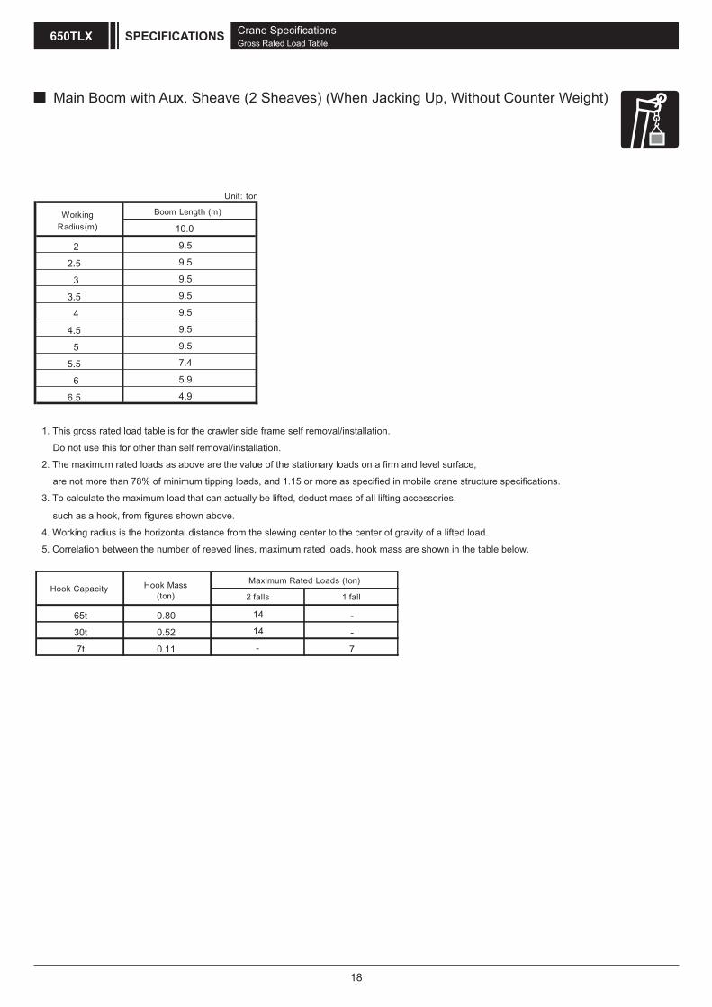
Main Boom with Aux. Sheave (2 Sheaves) (When Jacking Up, Without Counter Weight)
2
2.5
3
3.5
4
4.5
5
5.5
6
6.5
9.5
7.4
5.9
4.9
9.5
9.5
10.0
9.5
9.5
9.5
9.5
1. This gross rated load table is for the crawler side frame self removal/installation.
Do not use this for other than self removal/installation.
2. The maximum rated loads as above are the value of the stationary loads on a firm and level surface,
are not more than 78% of minimum tipping loads, and 1.15 or more as specified in mobile crane structure specifications.
65t 0.80
30t 0.52
7t 0.11
Maximum Rated Loads (ton)
14
14
Hook Capacity Hook Mass(ton)
such as a hook, from figures shown above.
4. Working radius is the horizontal distance from the slewing center to the center of gravity of a lifted load.
5. Correlation between the number of reeved lines, maximum rated loads, hook mass are shown in the table below.
2 falls
-
-- 7
1 fall
3. To calculate the maximum load that can actually be lifted, deduct mass of all lifting accessories,
WorkingRadius(m)
Boom Length (m)
Unit: ton
19
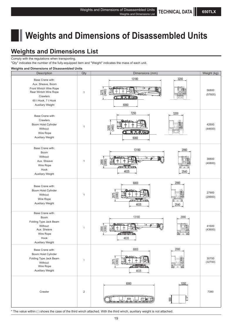
Weights and Dimensions of Disassembled UnitsDescription Qty Dimensions (mm) Weight (kg)
Base Crane with: Aux. Sheave, Boom
Front Wintch Wire RopeRear Wintch Wire Rope
Crawlers65 t Hook, 7 t Hook
Auxiliary Weight
1
6060
320013180
3275
(3460
) 56800 (57600)
Base Crane with:Crawlers
Boom Hoist CylinderWithout:
Wire RopeAuxiliary Weight
1
6060
725032
553200
(3460
) 42600(44600)
Base Crane with:Boom
Without: Aux. Sheave
Wire RopeHook
Auxiliary Weight
1
4635
2890
(3080
)
13180 2990
2540
38800(40800)
Base Crane with:Boom Hoist Cylinder
Without:Wire Rope
Auxiliary Weight
1
4635
6800
2875
(3080
)
2990
2540
27900(29900)
Base Crane with:Boom
Folding Type Jack Beam Without:
Aux. Sheave Wire Rope
HookAuxiliary Weight
1
13180
2890
(3080
)
4635
2990
41600(43600)
Base Crane with:Boom Hoist Cylinder
Folding Type Jack Beam Without:
Wire RopeAuxiliary Weight
1
2990
4635
6800
2875
(3080
) 30700(32700)
Crawler 2
6060 1050
990
7390
Weights and Dimensions of Disassembled UnitsWeights and Dimensions List
* The value within ( ) shows the case of the third winch attached. With the third winch, auxiliary weight is not attached.
Weights and Dimensions of Disassembled UnitsWeights and Dimensions List TECHNICAL DATA 650TLX
Comply with the regulations when transporting."Qty" indicates the number of the fully-equipped item and "Weight" indicates the mass of each unit.

20
Weights and Dimensions of Disassembled UnitsDescription Qty Dimensions (mm) Weight (kg)
Counter Weight (R) 2
940
790 735
2730
Counter Weight (L) 2
840735
950
2780
Counter Weight (Base) 1
2990
1100
330(3800) (1185)
* ( ) is attached the self assembly unit (OPT).
2960(2570)
Boom(with Aux. Sheave)
1
1300
1705
11205
11200
Folding Type Jack Beam 2 1400
Jack Beam 2
15701855
1080
1410
65 t Hook 1
660 455
1845
800
30 t Hook 1
350690
1540 520
7 t Hook 1
1320
190 160
105
Weights and Dimensions of Disassembled UnitsWeights and Dimensions ListTECHNICAL DATA650TLX
2000
750
1250

21
Equipment ListStandard and Optional Equipment TECHNICAL DATA 650TLX
Equipment ListStandard and Optional Equipment
○ : Standard ● : Optional
Item
Lower Structure
760 mm Crawler Shoe ○Crawler Extension/Retraction System ○Steps ○Folding Type Jack Beam*1 ●Jack Beam*1 ●Shoe Tension Unit (Hydraulic) ●
Upper Structure
Cab Up/Down Catwalk ○Upper House Handrails (For Catwalk) ○Under Cover (Bed Lower Surface) ○Working Light (× 2) ○Back Mirror (Left and Right) ○Drum Flange Cover ○Winch Rope Retainer (Front Winch) ●Winch Rope Retainer (Rear Winch) ○Winch Rope Retainer (Third Winch) ●Catwalk (Folding Type, Left and Right) ●Electric Fuel Pump ●Handrail (Folding Type) ●Front, Rear Winch ( 22.4mm with Free Fall, Brake Mode Select Switch) ○Third Winch ( 22.4mm without Free Fall, with Guide Sheave and Winch Drum Lock, and Rope not Included) ●Third Winch ( 22.4mm with Free Fall, Guide Sheave and Winch Drum Lock, and Rope not Included) ●Standard Counter Weight (2990mm Width) ○Counter Weight with Self Assembly Unit (Counter Weight 3800mm Width) ●
Cab
Air Conditioner ○Sunvisor ○Sunshade ○Wiper with Washer (Front Window, Cab Roof Window) ○Microphone & Loud-speaker ○AM / FM Radio (With Clock) ○Room Lamp ○Cup Holder ○24 V Power Socket (× 2) ○Floor Carpet ○Level Gauge (In Cab) ○Arm Chair Lever ○Accelerator Grip ○Accelerator Pedal (Right Side) ●Drum Rotation Sensor (Front/Rear) ○Speed Control Dial (Boom Hoist/Swing) ○Boom Hoist Operation Pedal ○Boom Hoist Operation Lever (Third Winch Lever is Replaced Forward) ●Fire Extinguisher (ABC No.4) ●Fan ●Life Hammer ○
*1 Jack beam and folding type jack beam cannot be attached at the same time.

22
○ : Standard ● : Optional
Item
Attachment
4-Section Telescopic Boom (10 to 30.1m) ○Boom Transportation Mount ●Boom Assembly/Disassembly Transport Mount ●Boom Foot Pin Assembly/Disassembly Jig and Tool ●Tool Box for Boom Foot Pin Assembly/Disassembly Jig ●Aux. Sheave (1 Sheave) [Aux. Sheave and Anti-two Block] ○Aux. Sheave (2 Sheaves) ●65 t Hook (5 Sheaves) ○30 t Hook (3 Sheaves) ●7t Hook (Light Type with Lock (105kg))* It may not fall by its own weight depends on the boom length. ○
Wire ropeFront Winch ( 22.4) XP IWRC6XWS (31) ○Rear Winch ( 22.4) XP IWRC6XWS (31) ○Third Winch ( 22.4) XP IWRC6XWS (31) ●
Safety Device
Moment Limiter ○3 Color Percentage Indicator Light ○Mode Select Switch (Crane/Excavation) ○Gate Lock Lever ○Individual Operation Lever Lock (Front, Rear, Boom Hoist, Travel) ○Winch Drum Lock (Front and Rear) ○Swing Lock ○Swing Alarm ○Travel Alarm ○Auto Slowdown (Slow Stop) ○Warning Alarm ○Engine Start Interlock System ○Emergency Engine Stop Switch (In Cab) ○Lifting Height Indication Device ○Swing Neutral Free/Brake Selection Switch ○Anti-two Block ○Swing Restriction Unit ●Drum and Rear View Monitor System (× 3) ●Cab Roof Window Guard ●
Common parts
Remote Sensing (Mobile Communication Terminal, Data Logging Device) ○Without Counter Weight (Reduced Counter Weight) Specification ○Hydraulic Power Outlet for Auger (Including the boom side piping, maximum pressure: 31.4MPa, maximum flow rate: 520L/min)
●
External Hydraulic Power Outlet A (Maximum Pressure: 13.7MPa, Maximum Flow Rate: 38L/min) ●External Hydraulic Power Outlet B (Maximum Pressure: 27.4MPa, Maximum Flow Rate: 150L/min) ●Auger Speed Selecter Panel (On the Right Side of the Cab) ●Sling Ropes for Disassembly and Assembly (for Counter Weights, Crawlers, Boom) ●Boom Stanchion ●Reeving Winch Cum Hydraulic Tagline (6 x Fi (29) 10mm x 55m) ● *2
Tool Box (On the Front of the Right Bed) ○Additional Fuel Filter (Triple Filter) ●Additional Spare Parts (Hydraulic Oil Filter) ●Additional Tools (Large Hammer, Crowbar, Chisel) ●
OtherStandard Supplied Tools ○Special Tools (When Hydraulic Power Outlet for Auger is Attached) ●Standard Spare Parts ○
*2 Reeving Winch Cum Hydraulic Tagline(Maxmum line pull: 1.4 kN (150 kgf) for hydraulic tagline / 2.9 kN (300 kgf) for reeving winch)
Equipment ListStandard and Optional EquipmentTECHNICAL DATA650TLX

M E M O 650TLX

• We are constantly improving our products and therefore reserve the right to change designs and speafications without notice. • Units in this specification are shown under International System of Units; the figures in parenthesis are under Gravitational System of Units as old one.
9-3, Higashi-Ueno 6-chome, Taito-ku, Tokyo 110-0015, JapanPhone: 81-3-3845-1387 Facsimile: 81-3-3845-1394http://www.hsc-cranes.com


