TUBE-O-THERM® Low Temperature Gas Burners 1 - 2.1 - 7E - i - 3/12
Specifications of TUBE-O-THERM® burners
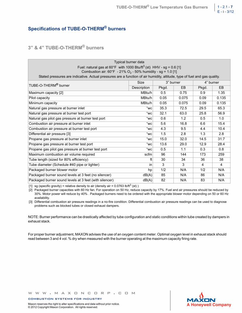
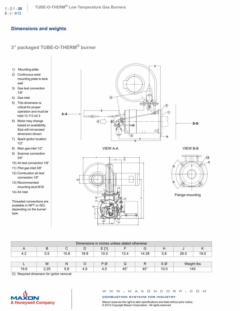
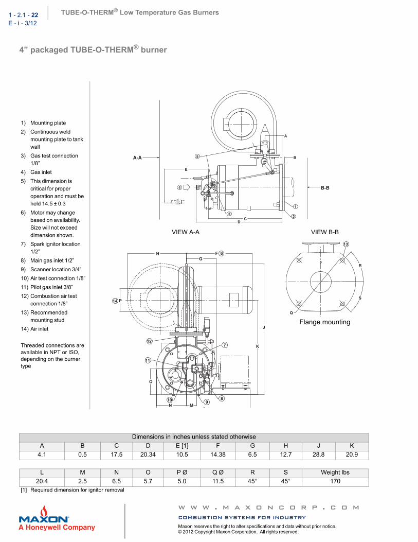
3” & 4” TUBE-O-THERM® burners
NOTE: Burner performance can be drastically affected by tube configuration and static conditions within tube created by dampers in exhaust stack.
For proper burner adjustment, MAXON advises the use of an oxygen content meter. Optimal oxygen level in exhaust stack should read between 3 and 4 vol. % dry when measured with the burner operating at the maximum capacity firing rate.
Typical burner data
Fuel: natural gas at 60°F with 1000 Btu/ft3 (st) HHV - sg = 0.6 [1]Combustion air: 60°F - 21% O2 - 50% humidity - sg = 1.0 [1]
Stated pressures are indicative. Actual pressures are a function of air humidity, altitude, type of fuel and gas quality.
TUBE-O-THERM® burnerSize 3” burner 4” burner
Description Pkgd. EB Pkgd. EB
Maximum capacity [2] MBtu/h 0.5 0.75 0.9 1.35
Pilot capacity MBtu/h 0.05 0.075 0.09 0.135
Minimum capacity MBtu/h 0.05 0.075 0.09 0.135
Natural gas pressure at burner inlet “wc 35.3 72.5 29.5 65.3
Natural gas pressure at burner test port “wc 32.1 63.0 25.8 56.9
Natural gas pilot gas pressure at burner test port “wc 0.6 1.2 0.5 1.0
Combustion air pressure at burner inlet “wc 5.6 16.8 6.6 15.4
Combustion air pressure at burner test port “wc 4.3 9.5 4.4 10.4
Differential air pressure [3] “wc 1.5 2.8 1.3 2.8
Propane gas pressure at burner inlet “wc 15.0 32.0 14.5 31.7
Propane gas pressure at burner test port “wc 13.6 29.0 12.9 28.4
Propane gas pilot gas pressure at burner test port “wc 0.5 1.1 0.3 0.8
Maximum combustion air volume required scfm 96 144 173 259
Tube length (sized for 80% efficiency) ft 30 34 36 38
Tube diameter (Schedule #40 pipe or lighter) in 3 3 4 4
Packaged burner blower motor hp 1/2 N/A 1/2 N/A
Packaged burner sound levels at 3 feet (no silencer) dB(A) 85 N/A 86 N/A
[1] sg (specific gravity) = relative density to air (density air = 0.0763 lb/ft3 (st) )[2] Packaged burner capacities with 60 Hz fan. For operation on 50 Hz, reduce capacity by 17%. Fuel and air pressures should be reduced by
30%. Motor power will reduce by 40% . Packaged burners need to be ordered with the appropriate blower motor depending on 50 or 60 Hz availability.
[3] Differential combustion air pressure readings in a no-fire condition. Differential combustion air pressure readings can be used to diagnose problems such as blocked tubes or closed exhaust dampers.
NOTE: Burner performance can be drastically affected by tube configuration and static conditions within tube created by dampers in exhaust stack.
For proper burner adjustment, MAXON advises the use of an oxygen content meter. Optimal oxygen level in exhaust stack should read between 3 and 4 vol. % dry when measured with the burner operating at the maximum capacity firing rate.
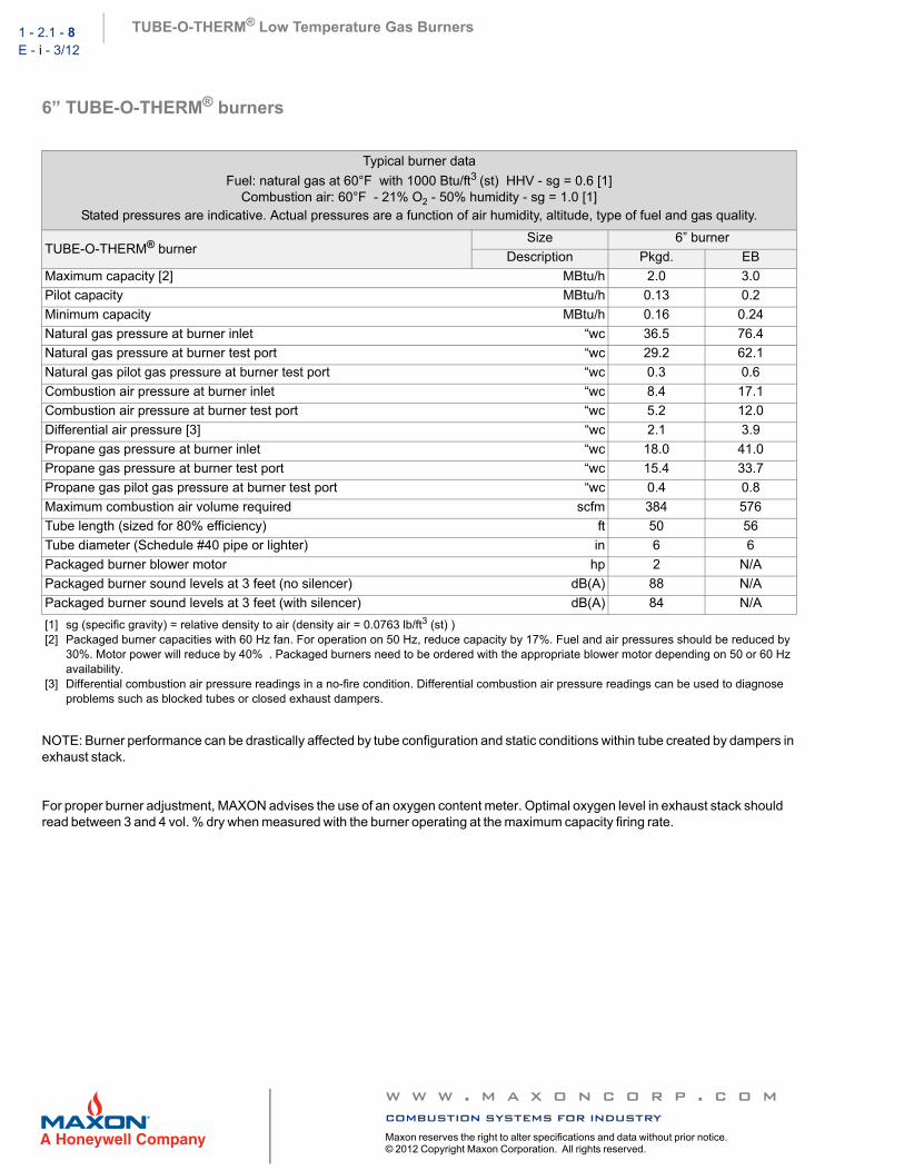
Typical burner data
Fuel: natural gas at 60°F with 1000 Btu/ft3 (st) HHV - sg = 0.6 [1]Combustion air: 60°F - 21% O2 - 50% humidity - sg = 1.0 [1]
Stated pressures are indicative. Actual pressures are a function of air humidity, altitude, type of fuel and gas quality.
TUBE-O-THERM® burnerSize 6” burner
Description Pkgd. EB
Maximum capacity [2] MBtu/h 2.0 3.0
Pilot capacity MBtu/h 0.13 0.2
Minimum capacity MBtu/h 0.16 0.24
Natural gas pressure at burner inlet “wc 36.5 76.4
Natural gas pressure at burner test port “wc 29.2 62.1
Natural gas pilot gas pressure at burner test port “wc 0.3 0.6
Combustion air pressure at burner inlet “wc 8.4 17.1
Combustion air pressure at burner test port “wc 5.2 12.0
Differential air pressure [3] “wc 2.1 3.9
Propane gas pressure at burner inlet “wc 18.0 41.0
Propane gas pressure at burner test port “wc 15.4 33.7
Propane gas pilot gas pressure at burner test port “wc 0.4 0.8
Maximum combustion air volume required scfm 384 576
Tube length (sized for 80% efficiency) ft 50 56
Tube diameter (Schedule #40 pipe or lighter) in 6 6
Packaged burner blower motor hp 2 N/A
Packaged burner sound levels at 3 feet (no silencer) dB(A) 88 N/A
[1] sg (specific gravity) = relative density to air (density air = 0.0763 lb/ft3 (st) )[2] Packaged burner capacities with 60 Hz fan. For operation on 50 Hz, reduce capacity by 17%. Fuel and air pressures should be reduced by
30%. Motor power will reduce by 40% . Packaged burners need to be ordered with the appropriate blower motor depending on 50 or 60 Hz availability.
[3] Differential combustion air pressure readings in a no-fire condition. Differential combustion air pressure readings can be used to diagnose problems such as blocked tubes or closed exhaust dampers.
TUBE-O-THERM® Low Temperature Gas Burners 1 - 2.1 - 9E - i - 3/12
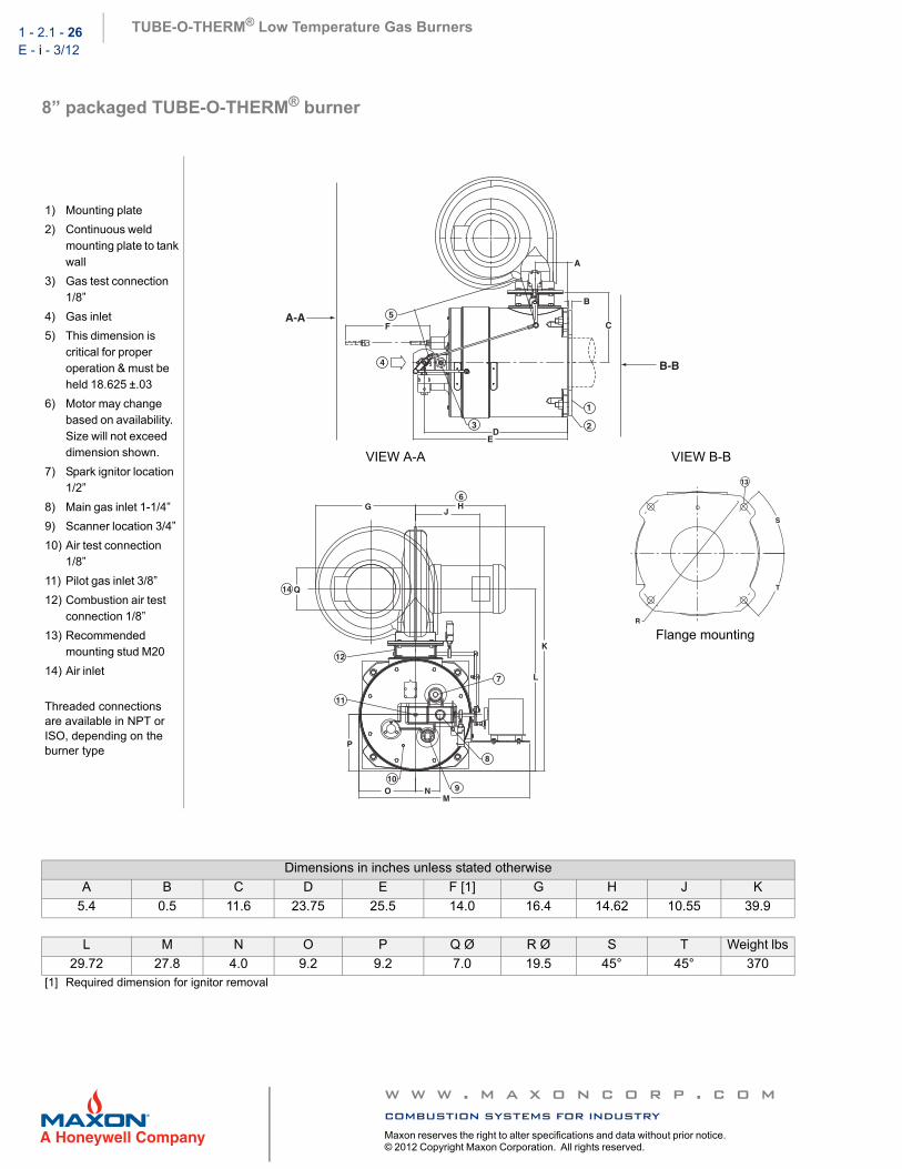
8” TUBE-O-THERM® burners
NOTE: Burner performance can be drastically affected by tube configuration and static conditions within tube created by dampers in exhaust stack.
For proper burner adjustment, MAXON advises the use of an oxygen content meter. Optimal oxygen level in exhaust stack should read between 3 and 4 vol. % dry when measured with the burner operating at the maximum capacity firing rate.
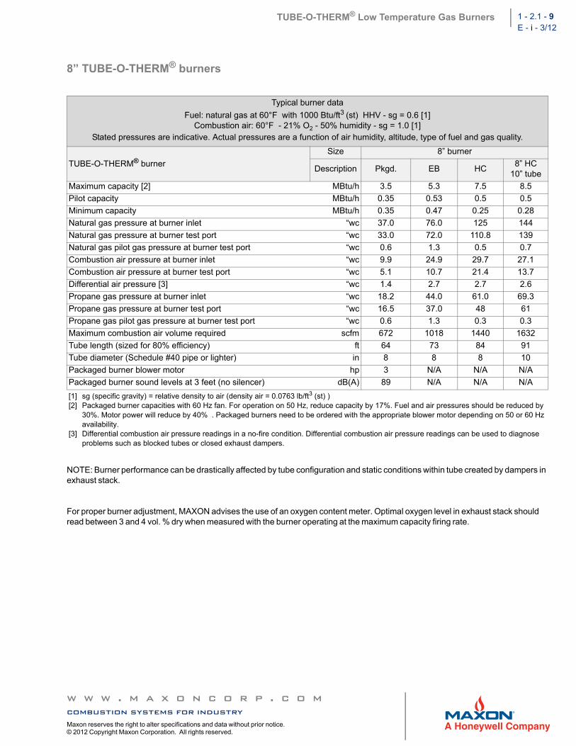
Typical burner data
Fuel: natural gas at 60°F with 1000 Btu/ft3 (st) HHV - sg = 0.6 [1]Combustion air: 60°F - 21% O2 - 50% humidity - sg = 1.0 [1]
Stated pressures are indicative. Actual pressures are a function of air humidity, altitude, type of fuel and gas quality.
TUBE-O-THERM® burner
Size 8” burner
Description Pkgd. EB HC8” HC
10” tube
Maximum capacity [2] MBtu/h 3.5 5.3 7.5 8.5
Pilot capacity MBtu/h 0.35 0.53 0.5 0.5
Minimum capacity MBtu/h 0.35 0.47 0.25 0.28
Natural gas pressure at burner inlet “wc 37.0 76.0 125 144
Natural gas pressure at burner test port “wc 33.0 72.0 110.8 139
Natural gas pilot gas pressure at burner test port “wc 0.6 1.3 0.5 0.7
Combustion air pressure at burner inlet “wc 9.9 24.9 29.7 27.1
Combustion air pressure at burner test port “wc 5.1 10.7 21.4 13.7
Differential air pressure [3] “wc 1.4 2.7 2.7 2.6
Propane gas pressure at burner inlet “wc 18.2 44.0 61.0 69.3
Propane gas pressure at burner test port “wc 16.5 37.0 48 61
Propane gas pilot gas pressure at burner test port “wc 0.6 1.3 0.3 0.3
Maximum combustion air volume required scfm 672 1018 1440 1632
Tube length (sized for 80% efficiency) ft 64 73 84 91
Tube diameter (Schedule #40 pipe or lighter) in 8 8 8 10
Packaged burner blower motor hp 3 N/A N/A N/A
Packaged burner sound levels at 3 feet (no silencer) dB(A) 89 N/A N/A N/A
[1] sg (specific gravity) = relative density to air (density air = 0.0763 lb/ft3 (st) )[2] Packaged burner capacities with 60 Hz fan. For operation on 50 Hz, reduce capacity by 17%. Fuel and air pressures should be reduced by
30%. Motor power will reduce by 40% . Packaged burners need to be ordered with the appropriate blower motor depending on 50 or 60 Hz availability.
[3] Differential combustion air pressure readings in a no-fire condition. Differential combustion air pressure readings can be used to diagnose problems such as blocked tubes or closed exhaust dampers.
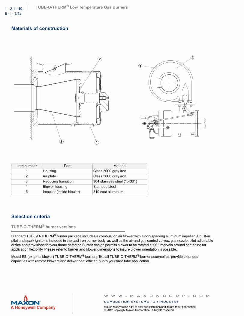
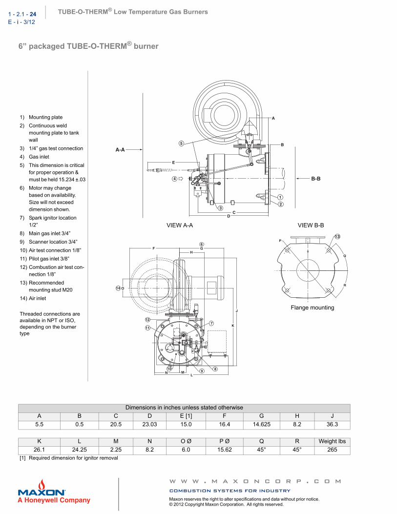
Standard TUBE-O-THERM® burner package includes a combustion air blower with a non-sparking aluminum impeller. A built-in pilot and spark ignitor is included in the cast iron burner body, as well as the air and gas control valves, gas nozzle, pilot adjustable orifice and provisions for your flame detector. Burner design permits blower to be rotated at 90° intervals around centerline for application flexibility. Please refer to burner and blower dimensions to insure blower orientation is possible.
Model EB (external blower) TUBE-O-THERM® burners, like all TUBE-O-THERM® burner assemblies, provide extended capacities with remote blowers and deliver heat efficiently into your fired tube application.
TUBE-O-THERM® Low Temperature Gas Burners 1 - 2.1 - 11E - i - 3/12
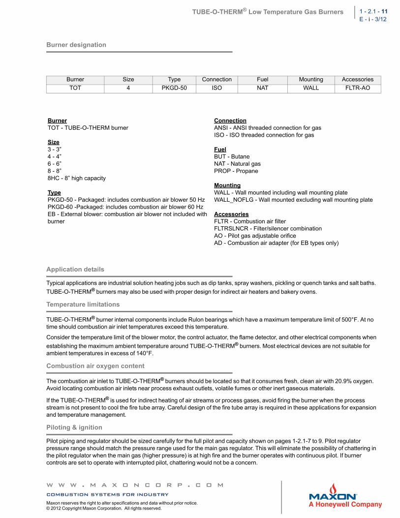
Burner designation
Application details
Typical applications are industrial solution heating jobs such as dip tanks, spray washers, pickling or quench tanks and salt baths.
TUBE-O-THERM® burners may also be used with proper design for indirect air heaters and bakery ovens.
Temperature limitations
TUBE-O-THERM® burner internal components include Rulon bearings which have a maximum temperature limit of 500°F. At no time should combustion air inlet temperatures exceed this temperature.
Consider the temperature limit of the blower motor, the control actuator, the flame detector, and other electrical components when
establishing the maximum ambient temperature around TUBE-O-THERM® burners. Most electrical devices are not suitable for ambient temperatures in excess of 140°F.
Combustion air oxygen content
The combustion air inlet to TUBE-O-THERM® burners should be located so that it consumes fresh, clean air with 20.9% oxygen. Avoid locating combustion air inlets near process exhaust outlets, volatile fumes or other inert gaseous materials.
If the TUBE-O-THERM® is used for indirect heating of air streams or process gases, avoid firing the burner when the process stream is not present to cool the fire tube array. Careful design of the fire tube array is required in these applications for expansion and temperature management.
Piloting & ignition
Pilot piping and regulator should be sized carefully for the full pilot and capacity shown on pages 1-2.1-7 to 9. Pilot regulator pressure range should match the pressure range used for the main gas regulator. This will eliminate the possibility of chattering in the pilot regulator when the main gas (higher pressure) is at high fire and the burner operates with continuous pilot. If burner controls are set to operate with interrupted pilot, chattering would not be a concern.
Burner Size Type Connection Fuel Mounting Accessories
TypePKGD-50 - Packaged: includes combustion air blower 50 HzPKGD-60 -Packaged: includes combustion air blower 60 HzEB - External blower: combustion air blower not included with burner
ConnectionANSI - ANSI threaded connection for gasISO - ISO threaded connection for gas
NOTE: The best option is to run the pilot interrupted. If the pilot is not interrupted, catalog minimums cannot be obtained. Some local codes may not allow the use of a continuous pilot. Mount pilot valve as close to the burner as possible. The pilot valve should be able to take 200” wc pressure at its outlet.
Refer to pages 1-2.1-7 to 9 for the proper pilot gas pressure as measured at the burner gas test port. The adjustable orifice inside the pilot can be used to establish the required pressure (5/32” hex wrench required). The pilot solenoid should be located close to the burner to allow gas to reach burner before flame safeguard “times out”.
The self-piloting feature of the burner allows pilot gas to bypass the internal gas control valve and issue from the main gas nozzle ports.
Low fire start: Main flame light-off is possible above minimum fire position, but a larger pilot will be required and turndown may be sacrificed if control design does not allow different light off and minimum positions. Direct ignition is feasible at capacities larger than full minimum. Again, turndown will not be sacrificed if control is separate for light off and minimum positions.
Ratio control
The TUBE-O-THERM® burner combustion air and fuel gas controls are factory-set and characterized to provide proper air/fuel ratios at specific supply pressures. Use combustion air blowers with relatively flat static pressure profiles (+/- 10%).
Regardless of the type of automatic control (high-low or modulating), TUBE-O-THERM® burners should not exceed 15% of maximum rating for pilot ignition and/or main flame light-off.
The built-in air and gas flow control valves are mechanically linked together. At low capacity, the air valve is slightly open but the gas valve is practically closed.
If some higher firing rate is selected for low fire on high-low installations, both valves will be opened wider. The increased combustion air will necessitate more gas for pilot ignition.
The burner’s maximum output may be limited by adjusting the linkage to the actuator motor. In these under-fired conditions, size combustion air blower to full maximum capacity due to the linkage profile and expected blower characteristic.
The TUBE-O-THERM® burner was designed to accept a variety of electric modulating motors. Contact MAXON for application details of your preferred actuator.
For more accurate gas/air ratio control, use MAXON SMARTLINK® MRV or MICRO-RATIO® valves on TUBE-O-THERM® burners without internal air/gas valves.
Typical ignition sequence
Pre-purge of burner and installation, according to the applicable codes and the installation’s requirements.
Combustion air control valve shall be in the minimum position to allow minimum combustion air flow to the burner.
Pre-ignition (typically 2s sparking in air).
Open pilot gas and continue to spark the ignitor (typically 5s).
Stop sparking, continue to power the pilot gas valves and start flame check. Trip burner if no flame can be detected from here on.
Check pilot flame stability (typically 5s) to prove the stable pilot.
Open main gas valves and allow enough time to have main gas in the burner (typically 5s + time required to have main gas in the burner).
Close the pilot gas valves.
Release to modulation (allow modulation of the burner).
Above sequences shall be completed to include all required safety checks during the start-up of the burner (process & burner safeties).
Flame supervision
The TUBE-O-THERM® burner will operate with a variety of flame detectors for all burner sizes. Flame rods are not available. Contact MAXON for specific questions on flame detection.
TUBE-O-THERM® Low Temperature Gas Burners 1 - 2.1 - 13E - i - 3/12
Piping
Main gas train should be sized to give no more than 6” wc pressure drop between gas pressure regulator and burner inlet to obtain catalog minimums. It is recommended to size the regulator for capacity at the required pressure, carefully considering pipe train losses.
Fuels
Natural gas, propane, butane and other commercially available fuel gases can be used. Fuel pressures in capacity tables are listed for natural gas and propane gas. Adjust operating fuel pressures and flows according to your fuel.
Expected emissions
TUBE-O-THERM® burners utilize rapid mixing of fuel and air to suppress formation of NOx. Typical NOx formation from the burner will be 30-40% less than conventional burners.
With lower levels of excess air than many tube burners, the TUBE-O-THERM® also controls the production of CO to low levels at most of its firing rate. Higher levels of excess air are used at lower firing rates to prevent condensation in the fire tube which elevates CO production at minimum and idle input. Expect little or no CO at high firing rates with low fire CO production determined by process parameters.
Exact emissions performance may vary in your application. Contact MAXON for information on installation specific estimates or guarantees. No guarantee of emissions is intended or implied without specific written guarantee from MAXON.
Tube length and configuration
Tube design should consist of a specified length of Schedule #40 pipe or lighter in the same size as burner (unless specified
otherwise). Tubes may be constructed of iron, steel, or stainless steel. It is possible to fire TUBE-O-THERM® burners into tube diameters larger than the size designation. Contact your MAXON representative for further information on tube sizing or material selection.
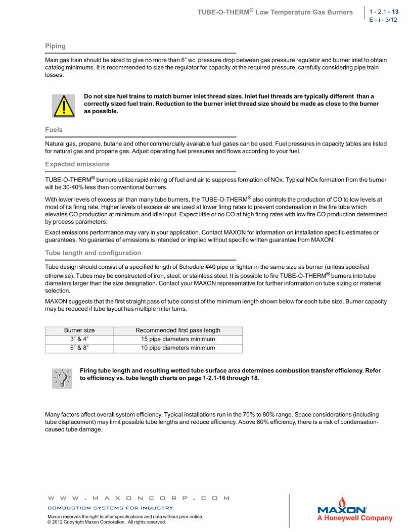
MAXON suggests that the first straight pass of tube consist of the minimum length shown below for each tube size. Burner capacity may be reduced if tube layout has multiple miter turns.
Many factors affect overall system efficiency. Typical installations run in the 70% to 80% range. Space considerations (including tube displacement) may limit possible tube lengths and reduce efficiency. Above 80% efficiency, there is a risk of condensation-caused tube damage.
Do not size fuel trains to match burner inlet thread sizes. Inlet fuel threads are typically different than a correctly sized fuel train. Reduction to the burner inlet thread size should be made as close to the burner as possible.
Burner size Recommended first pass length
3” & 4” 15 pipe diameters minimum
6” & 8” 10 pipe diameters minimum
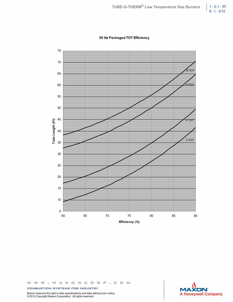
Firing tube length and resulting wetted tube surface area determines combustion transfer efficiency. Refer to efficiency vs. tube length charts on page 1-2.1-16 through 18.
Small bore immersion tubes can be sized for efficiencies lower than 80% if tank space is limited or if complete freedom from tube condensation is desired.
NOTE: Schedule 40 pipe should be used for at least the first 2 feet of tube length.
Tube exhaust requirements
Historically, conventional immersion tube burners were sized for 70% efficiency, since this percentage provided a compromise between operating fuel economy and tube length.
Small-bore tubes require less space than conventional tubes. Therefore, small-bore tubes can be made longer to provide efficiencies of 80% or more.
Tubes sized for 80% efficiency will have low exhaust temperatures, causing condensation to form in them during start-up or during long idling periods. This condensation will normally evaporate after the burner has run at high fire for a brief period of time. If extended idling periods are expected, a condensate drain should be provided at the low point nearest the exhaust and the immersion tube should be pitched towards the exhaust.
If the immersion tube will operate at efficiencies of 75% or lower, the exhaust leg can exit through the liquid surface in the tank without designing for condensation. However, the length of the exhaust tube must also be considered in the design as explained below.
These considerations also extend to the exhaust lengths after the tube exits the liquid surface. An exhaust tube exiting the tank will continue to transfer heat and cool the products of combustion to their condensation point. Therefore, an atmospheric break or dilution tee should be used. By doing so, the diluting atmospheric air will depress the dewpoint temperature of the combustion products so that they may exhaust out of the plant with minimal condensation.
If the dilution tee option is chosen, there must be safeguards to ensure that the diluting air is not restricted or blocked. If this were to occur, condensation inside the stack could result, with condensate flowing downward to the low point in the tube, possibly blocking the tube and causing burner instability.
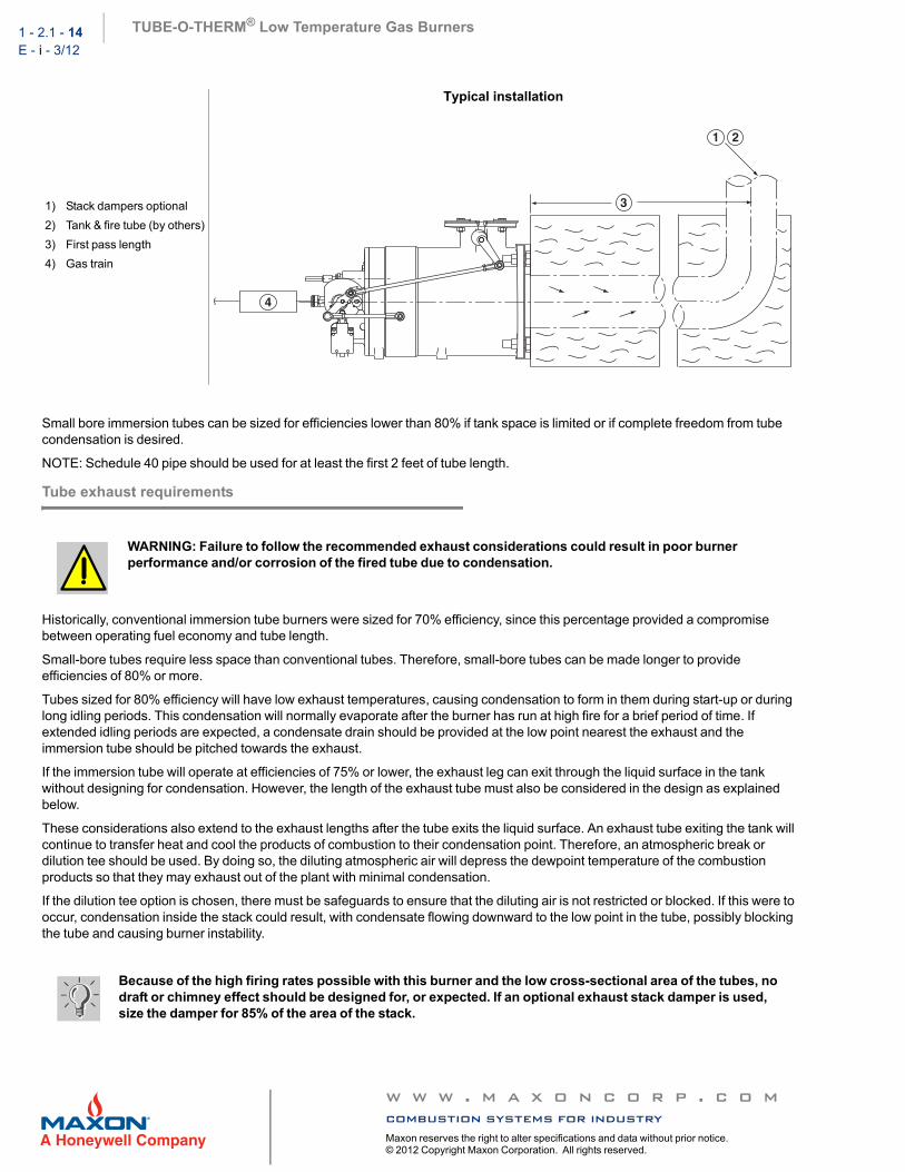
1) Stack dampers optional
2) Tank & fire tube (by others)
3) First pass length
4) Gas train
Typical installation
WARNING: Failure to follow the recommended exhaust considerations could result in poor burner performance and/or corrosion of the fired tube due to condensation.
Because of the high firing rates possible with this burner and the low cross-sectional area of the tubes, no draft or chimney effect should be designed for, or expected. If an optional exhaust stack damper is used, size the damper for 85% of the area of the stack.
TUBE-O-THERM® Low Temperature Gas Burners 1 - 2.1 - 15E - i - 3/12
Immersion tubes are usually vented to the outdoors, except for those in highly ventilated areas such as a plating room with continuous high-volume exhaust. An exhaust fan is generally not required but may be used in cases of high building negative pressure. Exhaust is normally diluted to avoid the need for high-temperature fans, but adequate make-up air must be available.
This diluting can be done with an open tee installed in a vertical run (or in a horizontal run with the open end down), but such a system mixes slowly.
An adjustable hood (shown in sketch below) offers much better performance. In all cases, care must be taken that all products of combustion are exhausted from the building.
Note that TUBE-O-THERM® burners release heat beginning at the burner mounting surface. In most cases, the fire tube must be fluid backed. Extension stubs or insulated fire tube entries are not recommended and risk thermal damage to the burner, structure and the tube.
1) To outdoors or exhaust fan
2) Diluting air tee
3) All adjustments to be locked in position
4) Adjustable hood
5) Diluting air
6) Immersion tube
7) Exhaust stack damper
Cross-sectional area of the exhaust hood should be a minimum of 1.5 times the fired tube cross-sectional area.
Because of the high firing rates possible with this burner and the low cross-sectional area of the tubes, no draft or chimney effect should be designed for, or expected. If an optional exhaust stack damper is used, size the damper for 85% of the area of the stack. The use of an exhaust stack damper could also help solve resonance in some cases.
Systems sized for 80% efficiencies or higher need to account for condensation during extended idling periods. Refer to Selec-tion Criteria on pages 1-2.1-10.
Use the centerline lengths of elbows when computing total tube length.
Note that longer tube lengths are required to achieve the same efficiency on external blower (EB) versions. This is due to increased maximum firing rate.
When a burner will not be firing at its maximum capacity, the tube length will decrease to maintain the same efficiency. Contact MAXON for tube length calculations in these cases.
TUBE-O-THERM® Low Temperature Gas Burners 1 - 2.1 - 19E - i - 3/12
Indirect firing
Tube sizing charts are applicable only to liquid-backed immersion tubes. Indirect-fired applications (non-liquid backed fired tubes) could require additional length depending on the specific application. For indirect firing in moving air streams, the tube sizing charts will look different. Contact MAXON for more details on these applications.
Recommended air stream velocity across fired tubes is 2000 to 3000 fpm .
Multiple burner arrangement
Multiple burner installations fed by a single pipe train should incorporate a balancing valve and a swing check valve installed as close as possible to each burner gas inlet for improved heating uniformity and more dependable light-off. Otherwise, gas manifold may act as a reservoir, preventing reliable light-off during trial for ignition period of your control panel sequence.
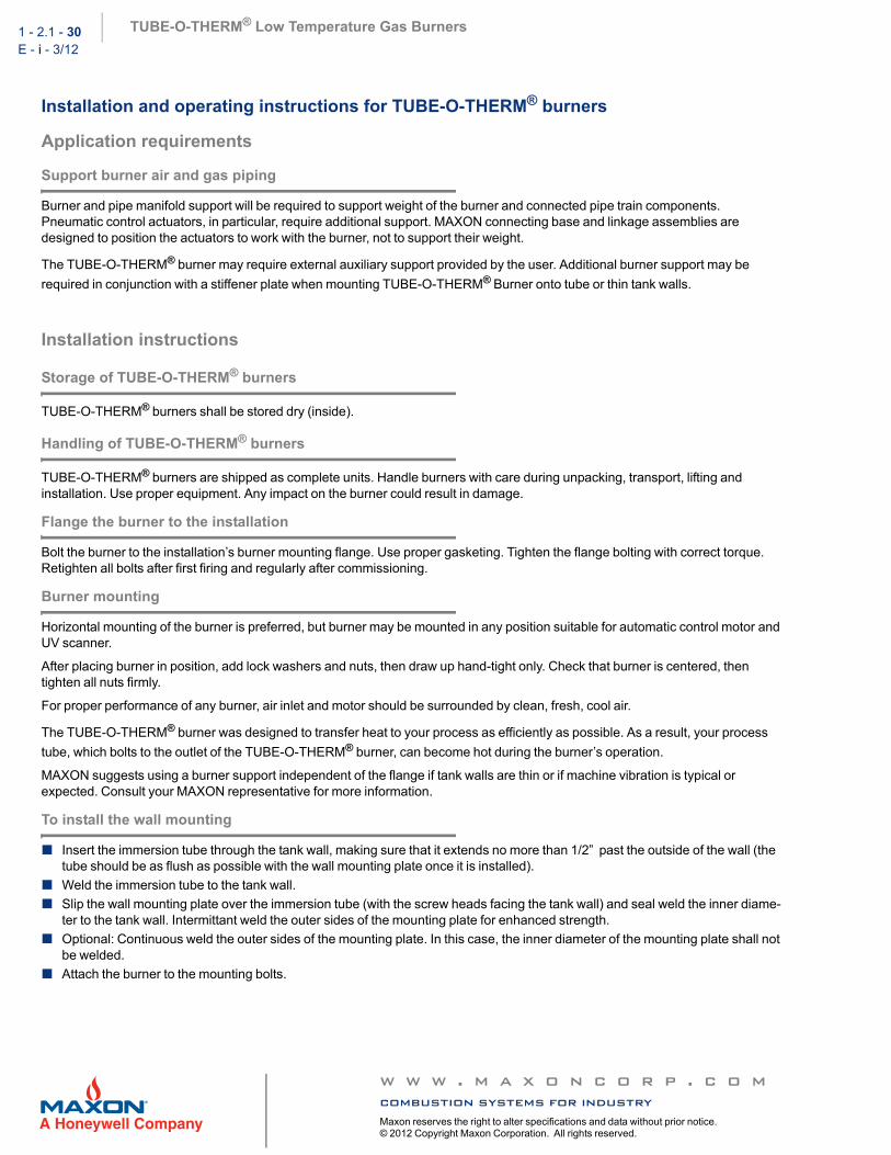
Installation and operating instructions for TUBE-O-THERM® burners
Application requirements
Support burner air and gas piping
Burner and pipe manifold support will be required to support weight of the burner and connected pipe train components. Pneumatic control actuators, in particular, require additional support. MAXON connecting base and linkage assemblies are designed to position the actuators to work with the burner, not to support their weight.
The TUBE-O-THERM® burner may require external auxiliary support provided by the user. Additional burner support may be
required in conjunction with a stiffener plate when mounting TUBE-O-THERM® Burner onto tube or thin tank walls.
Installation instructions
Storage of TUBE-O-THERM® burners
TUBE-O-THERM® burners shall be stored dry (inside).
Handling of TUBE-O-THERM® burners
TUBE-O-THERM® burners are shipped as complete units. Handle burners with care during unpacking, transport, lifting and installation. Use proper equipment. Any impact on the burner could result in damage.
Flange the burner to the installation
Bolt the burner to the installation’s burner mounting flange. Use proper gasketing. Tighten the flange bolting with correct torque. Retighten all bolts after first firing and regularly after commissioning.
Burner mounting
Horizontal mounting of the burner is preferred, but burner may be mounted in any position suitable for automatic control motor and UV scanner.
After placing burner in position, add lock washers and nuts, then draw up hand-tight only. Check that burner is centered, then tighten all nuts firmly.
For proper performance of any burner, air inlet and motor should be surrounded by clean, fresh, cool air.
The TUBE-O-THERM® burner was designed to transfer heat to your process as efficiently as possible. As a result, your process
tube, which bolts to the outlet of the TUBE-O-THERM® burner, can become hot during the burner’s operation.
MAXON suggests using a burner support independent of the flange if tank walls are thin or if machine vibration is typical or expected. Consult your MAXON representative for more information.
To install the wall mounting
Insert the immersion tube through the tank wall, making sure that it extends no more than 1/2” past the outside of the wall (the tube should be as flush as possible with the wall mounting plate once it is installed).
Weld the immersion tube to the tank wall.
Slip the wall mounting plate over the immersion tube (with the screw heads facing the tank wall) and seal weld the inner diame-ter to the tank wall. Intermittant weld the outer sides of the mounting plate for enhanced strength.
Optional: Continuous weld the outer sides of the mounting plate. In this case, the inner diameter of the mounting plate shall not be welded.
TUBE-O-THERM® Low Temperature Gas Burners 1 - 2.1 - 31E - i - 3/12
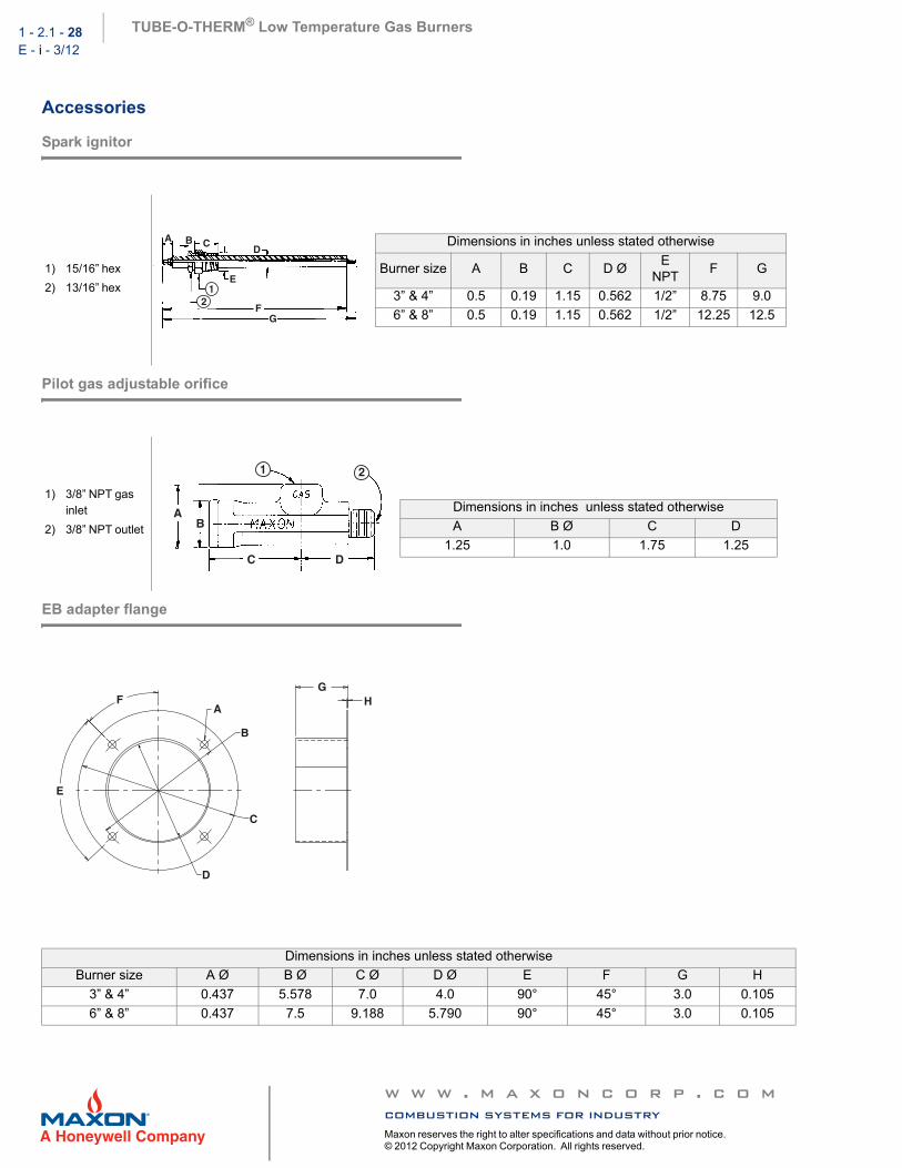
Protective covers
Protective covers for burner should be added in the field if exposure to dripping condensate, splashing flux, exhaust steam, etc. is unavoidable. Any such cover should be removable to provide access to burner and should not interfere with control linkage motion, observation port viewing or air inlet.
1) TUBE-O-THERM® burner
2) Tank wall (customer’s) - immersion tube should extend no more than 1/2” past this outside wall
3) Wall mounting plate (MAXON) (to be welded to customer’s tank)
4) Gasket (MAXON) - high temperature sealant applied between burner body and gasket only
5) Existing weld - tank wall/tube
6) Immersion tube (customer’s)
7) I.D. of MAXON-supplied mounting plate is 3/4” larger than O.D. of tube. This is to allow a gap for weld clearance where the tube welds to the tank wall.
8) Seal weld I.D.
In some applications, the burner housing may become significantly warm. While this does not damage the burner or impede performance, guards or protective material may be required to protect personnel from burn hazards.
To prevent damage in transit, the spark ignitor, mounting ring, flame detector and connecting linkage com-ponents may be packed separately and shipped loose with the burner.
Instructions provided by the company or individual responsible for the manufacture and/or overall installa-tion of a complete system incorporating MAXON burners take precedence over the installation and operat-ing instructions provided by MAXON. If any of the instructions provided by MAXON are in conflict with local codes or regulations, please contact MAXON before initial start-up of equipment.
Safety interlocks
Guarantee that all the required safety locks as described in the applicable codes or regulations, or supplementary safety blocks requested for safe operation of the overall installation, are working properly and resulting in a positive safety-lock of the burner. Do not bypass any of these safety interlocks. This will result in unsafe operation.
Checks during and after start-up
During and after start-up, check the integrity of the system. Check all bolted connections after first firing (first time on temperature) and retighten if necessary.
Purge
For safety reasons, it is required to purge the installation sufficiently to ensure that all possible combustibles are evacuated before ignition. Refer to the applicable local codes and your specific application requirements to determine the purge time.
Pilot ignition
Before ignition of the pilot, adjust the combustion air to the minimum burner air flow. Pilot will not ignite if too high an air flow. Set pilot gas flow to the correct value before pilot ignition attempt.
Main burner ignition
Set correct gas flow for burner minimum capacity before attempt of main burner ignition.
After ignition of main burner, allow some time on minimum capacity to allow the burner parts to heat up slowly.
Adjust air/gas ratio. Set maximum capacity.
Once the main flame is ignited, adjust air/gas ratio of the burner to have the required combustion quality and slowly increase capacity.
Important: Do not discard packing material until all loose items are accounted for.
Read the combustion system manual carefully before initiating the start-up and adjustment procedure. Verify that all of the equipment associated with and necessary to the safe operation of the burner system has been installed correctly, that all pre-commissioning checks have been carried out successfully and that all safety-related aspects of the installation are properly addressed.
Initial adjustment and light-off should be undertaken only by a trained commissioning engineer.
TUBE-O-THERM® Low Temperature Gas Burners 1 - 2.1 - 33E - i - 3/12
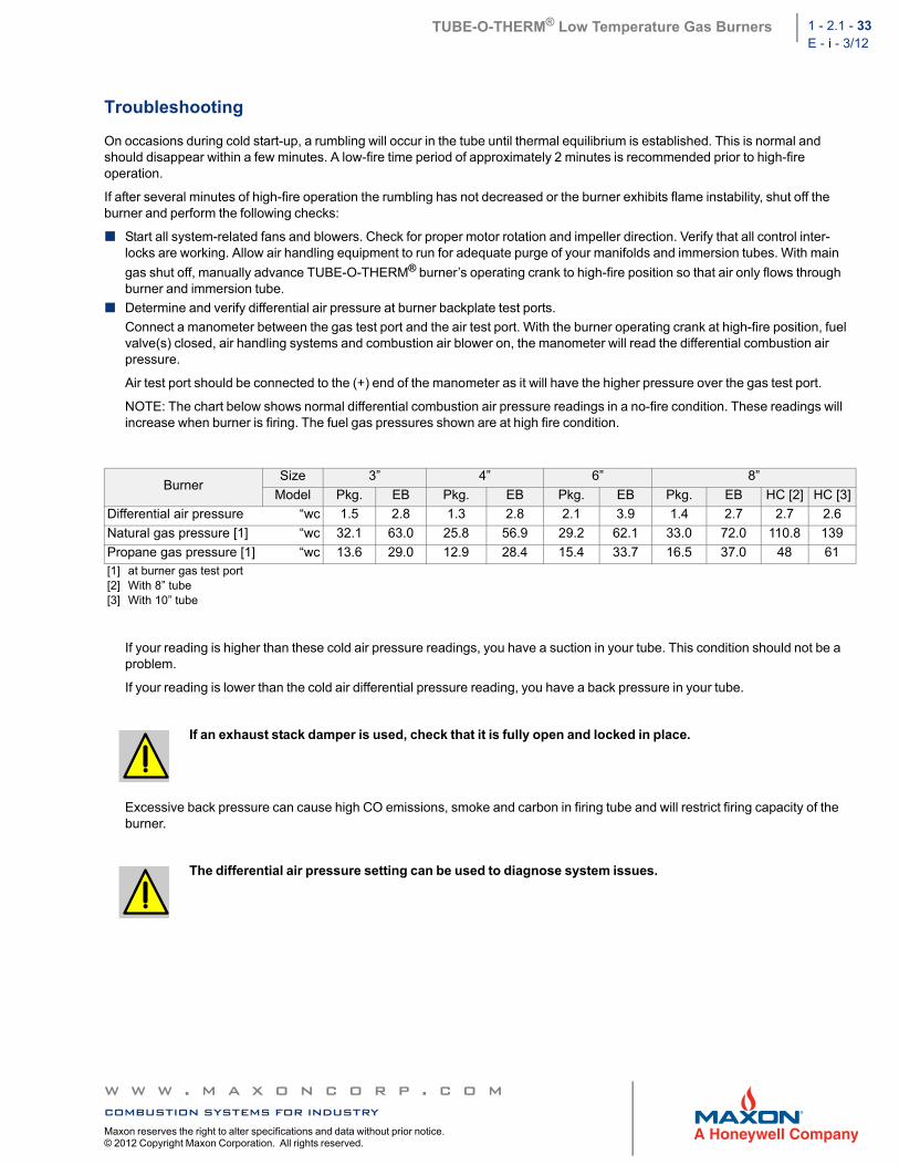
Troubleshooting
On occasions during cold start-up, a rumbling will occur in the tube until thermal equilibrium is established. This is normal and should disappear within a few minutes. A low-fire time period of approximately 2 minutes is recommended prior to high-fire operation.
If after several minutes of high-fire operation the rumbling has not decreased or the burner exhibits flame instability, shut off the burner and perform the following checks:
Start all system-related fans and blowers. Check for proper motor rotation and impeller direction. Verify that all control inter-locks are working. Allow air handling equipment to run for adequate purge of your manifolds and immersion tubes. With main
gas shut off, manually advance TUBE-O-THERM® burner’s operating crank to high-fire position so that air only flows through burner and immersion tube.
Determine and verify differential air pressure at burner backplate test ports.
Connect a manometer between the gas test port and the air test port. With the burner operating crank at high-fire position, fuel valve(s) closed, air handling systems and combustion air blower on, the manometer will read the differential combustion air pressure.
Air test port should be connected to the (+) end of the manometer as it will have the higher pressure over the gas test port.
NOTE: The chart below shows normal differential combustion air pressure readings in a no-fire condition. These readings will increase when burner is firing. The fuel gas pressures shown are at high fire condition.
If your reading is higher than these cold air pressure readings, you have a suction in your tube. This condition should not be a problem.
If your reading is lower than the cold air differential pressure reading, you have a back pressure in your tube.
Excessive back pressure can cause high CO emissions, smoke and carbon in firing tube and will restrict firing capacity of the burner.
BurnerSize 3” 4” 6” 8”
Model Pkg. EB Pkg. EB Pkg. EB Pkg. EB HC [2] HC [3]
All TUBE-O-THERM® burners are shipped with the air/gas linkage factory set. Check centerline to centerline dimensions on the air/gas linkage to determine that it is proper length per dimension #5 on pages 1-2.1-19 to 26. The linkage is fabricated as a turnbuckle-style link. To adjust, simply loosen the locknut and twist the arm clockwise to shorten, or counter-clockwise to lengthen the linkage.
If air/gas linkage dimension is correct per dimensions shown on pages 1-2.1-19 to 26, check wiring diagram to blower motor to determine that dual voltage motor has been wired properly. Failure to do so will result in differential air pressure readings that are out of specification. Correct wiring errors as necessary.
If stack damper is used in error, make certain it is full open and locked (may need to be removed).
Burner performance can be drastically affected by tube configuration and static conditions within tube created by dampers in exhaust stack.
TUBE-O-THERM® Low Temperature Gas Burners 1 - 2.1 - 35E - i - 3/12
Maintenance & inspection instructions
Safety requirements
Regular inspection, testing and recalibration of combustion equipment according to the installation manual is an integral part of its safety. Inspection activities and frequencies shall be carried out as specified in the installation manual.
Visual inspections
Regular visual inspection of all connections (air and gas piping to the burner, bolting of the burner to the tank wall) and burner flame size and aspect are essential.
In normal operation, little more is required than periodic checking to see that control motor linkage has not slipped from adjustment and that burner remains tightly mounted to the firing tube.
Burner should be shielded from splashing and physical abuse.
Inspect impeller for proper rotation, speed and dirt build-up which might reduce air flow. If your system includes an air filter, schedule maintenance as required for your plant environment.
Combustion air filters
Always keep air filters clean for optimum system performance.
Clean as needed to remove any dry accumulations. To remove oil and dirt, wash elements in hot water and detergent as necessary.
Replaceable elements can be wrung gently and allowed to air dry before returning to service. Permanent elements should generally be blown dry after rinsing, and if desired, a light coating of suitable oil applied.
To avoid interruption to service, you may wish to order a spare element set.
Flame sensing
Flame sensing is accomplished by a UV scanner. Keep scanner as close to burner as feasible. Use only minimal cooling air to scanner port. Excessive cooling air flow can impede flame detection.
Recommended spare parts
Keep local stock of spark ignitor. It is not recommended to keep local stock of other burner parts. Consult installation manual for burner spare parts and system accessories.


![Therm L1 [Basics]](https://static.documents.pub/doc/80x56/577d276d1a28ab4e1ea3e5da/therm-l1-basics.jpg)
