42
Technical Specifications Smart-UPS VT 10-30 kVA 208 V

TechnicalSpecificationsSmart-UPS VT 10-30 kVA 208 V
test

American Power Conversion Legal Disclaimer
The information presented in this manual is not warranted by the American Power ConversionCorporation to be authoriative, error free, or complete. This publication is not meant to bea substitute for detailed operational and site specific development plan. Therefore, AmericanPower Conversion Corporation assumes no liability for damages, violations of codes, improperinstallation, system failures, or any other problems that could arise based on the use of thisPublication.
The information contained in this Publication is provided as is and has been prepared solelyfor the purpose of evaluating data center design and construction. This Publication has beencompiled in good faith by American Power Conversion Corporation. However, no presentationis made or warranty, either express or implied, as to the completeness or accuracy of theinformation this Publication contains.
IN NO EVENT SHALL AMERICAN POWER CONVERSION CORPORATION BELIABLE FOR ANY DIRECT, INDIRECT, CONSEQUENTIAL, PUNITIVE, SPECIAL, ORINCIDENTAL DAMAGES (INCLUDING, WITHOUT LIMITATION, DAMAGES FORLOSS OF BUSINESS, CONTRACT, REVENUE, DATA, INFORMATION, OR BUSINESSINTERRUPTION) RESULTING FROM, ARISING OUT, OR IN CONNECTION WITH THEUSE OF, OR INABILITY TO USE THIS PUBLICATION OR THE CONTENT, EVEN IFAMERICAN POWER CONVERSION CORPORATION HAS BEEN EXPRESSLY ADVISEDOF THE POSSIBILITY OF SUCH DAMAGES. AMERICAN POWER CONVERSIONCORPORATION RESERVES THE RIGHT TO MAKE CHANGES OR UPDATES WITHRESPECT TO OR IN THE CONTENT OF THE PUBLICATION OR THE FORMATTHEREOF AT ANY TIME WITHOUT NOTICE.
Copyright, intellectual, and all other proprietary rights in the content (including but not limitedto software, audio, video, text, and photographs) rests with American Power ConversionCorporation or its licensors. All rights in the content not expressly granted herein are reserved.No rights of any kind are licensed or assigned or shall otherwise pass to persons accessingthis information.
This Publication shall not be for resale in whole or in part.

Table of Contents
Technical Data .................................................................................................................. 1
Model List....................................................................................................................... 1
Input Power Factor ...................................................................................................... 2
Efficiency........................................................................................................................ 2Efficiency Curves....................................................................................................... 2
Derating due to Load Power Factor ........................................................................ 4
Batteries ......................................................................................................................... 4Efficiency DC to AC ................................................................................................... 4Battery Run-Times - APC Battery Solution ................................................................ 4Battery Run-Times - Non-Modular Batteries .............................................................. 9Battery Discharge Current .........................................................................................10End of Discharge Voltage at 100% Load ....................................................................10Battery Gassing Rates ...............................................................................................11Electrolyte Values for SYBTU1–PLP ..........................................................................13Battery Material Safety Data Sheet ............................................................................13
Communication and Management ..........................................................................13Network Management Card........................................................................................13Input and Output Contacts ........................................................................................14
EPO in Single Systems...............................................................................................15
EPO in Parallel Systems ............................................................................................16
Compliance ....................................................................................................................16
Facility Planning .............................................................................................................17
AC Input Specifications..............................................................................................17
AC Bypass Input Specifications ..............................................................................17
AC Output Specifications ..........................................................................................18
Battery Specifications ................................................................................................18
Recommended Cable Sizes ......................................................................................19Connection Terminals................................................................................................19Torque Specifications ................................................................................................19
Fuses and Breakers ....................................................................................................20Single Utility/Mains System .......................................................................................20Dual Utility/Mains System ..........................................................................................20Parallel System ..........................................................................................................21Fuse and Breaker Sizes in Single Systems................................................................21Fuse and Breaker Sizes in Parallel Systems..............................................................21
990-3882A-001 Smart-UPS VT 10-30 kVA 208 V Technical Specifications i

Minimum Breaker Settings ........................................................................................22
Physical ..........................................................................................................................22Weights and Dimensions ...........................................................................................22Shipping Weights and Dimensions............................................................................23Clearance...................................................................................................................24
Environmental...............................................................................................................24Heat Dissipation ........................................................................................................25
Default Settings ............................................................................................................26
Drawings .............................................................................................................................27
Single Feed without MBP...........................................................................................28
Dual Feed without MBP ..............................................................................................30
Options .................................................................................................................................32
Hardware Options ........................................................................................................32Battery Systems ........................................................................................................32Management Cards and Options ...............................................................................32Interface Cables.........................................................................................................32Mounting Accessories ...............................................................................................32Service Bypass Panels ..............................................................................................33Smart-UPS Accessories.............................................................................................33
Parallel Capabilities.....................................................................................................34Paralleling Capabilities ..............................................................................................34
APC by Schneider Electric Limited Factory Warranty ..............................35
Three Phase Power Products or Cooling Solutions One-Year FactoryWarranty .........................................................................................................................35
Terms of Warranty........................................................................................................35
Non-transferable Warranty ........................................................................................35
Assignment of Warranties .........................................................................................35
Drawings, Descriptions ..............................................................................................35
Exclusions .....................................................................................................................35
Warranty Claims ...........................................................................................................36
ii Smart-UPS VT 10-30 kVA 208 V Technical Specifications 990-3882A-001

Technical Data
Model List
SUVTP10KF1B2S APC Smart-UPS VT 10kVA 208V w/1 Batt Mod Exp to 2,Start-Up 5X8, Int Maint Bypass, Parallel Capable
SUVTP10KF1B4S APC Smart-UPS VT 10kVA 208V w/1 Batt Mod Exp to 4,Start-Up 5X8, Int Maint Bypass, Parallel Capable
SUVTP10KF2B2S APC Smart-UPS VT 10kVA 208V w/2 Batt. Mod., Start-Up5X8, Internal Maint Bypass, Parallel Capability
SUVTP10KF2B4S APC Smart-UPS VT 10kVA 208V w/2 Batt Mod Exp to 4,Start-Up 5X8, Int Maint Bypass, Parallel Capable
SUVTP10KF3B4S APC Smart-UPS VT 10kVA 208V w/3 Batt Mod Exp to 4,Start-Up 5X8, Int Maint Bypass, Parallel Capable
10 kVA
SUVTP10KF4B4S APC Smart-UPS VT 10kVA 208V w/4 Batt Mod., Start-Up 5X8,Int Maint Bypass, Parallel Capable
SUVTP15KF2B2S APC Smart-UPS VT 15kVA 208V w/2 Batt Mod., Start-Up 5X8,Int Maint Bypass, Parallel Capable
SUVTP15KF2B4S APC Smart-UPS VT 15kVA 208V w/2 Batt Mod Exp to 4,Start-Up 5X8, Int Maint Bypass, Parallel Capable
SUVTP15KF3B4S APC Smart-UPS VT 15kVA 208V w/3 Batt Mod Exp to 4,Start-Up 5X8, Int Maint Bypass, Parallel Capable
15 kVA
SUVTP15KF4B4S APC Smart-UPS VT 15kVA 208V w/4 Batt Mod, Start-Up 5X8,Int Maint Bypass, Parallel Capable
SUVTP20KF2B4S APC Smart-UPS VT 20kVA 208V w/2 Batt Mod Exp to 4,Start-Up 5X8, Int Maint Bypass, Parallel Capable
SUVTP20KF3B4S APC Smart-UPS VT 20kVA 208V w/3 Batt Mod Exp to 4,Start-Up 5X8, Int Maint Bypass, Parallel Capable
20 kVA
SUVTP20KF4B4S APC Smart-UPS VT 20kVA 208V w/4 Batt. Mod., Start-Up5X8, Internal Maint Bypass, Parallel Capability
SUVTP30KF3B4S APC Smart-UPS VT 30kVA 208V w/3 Batt Mod Exp to 4,Start-Up 5X8, Int Maint Bypass, Parallel Capable
30 kVA
SUVTP30KF4B4S APC Smart-UPS VT 30kVA 208V w/4 Batt. Mod., Start-Up5X8, Internal Maint Bypass, Parallel Capability
990-3882A-001 Smart-UPS VT 10-30 kVA 208 V Technical Specifications 1

Input Power Factor
EfficiencySystem 25% load 50% load 75% load 100% load
10 kVA 208 V 87.5 91.8 92.9 93.2
15 kVA 208 V 90.4 92.9 93.1 93
20 kVA 208 V 88.6 92.4 93.3 93.4
30 kVA 208 V 91.2 93.3 93.3 93.1
Efficiency Curves
10 kVA 208 V
2 Smart-UPS VT 10-30 kVA 208 V Technical Specifications 990-3882A-001
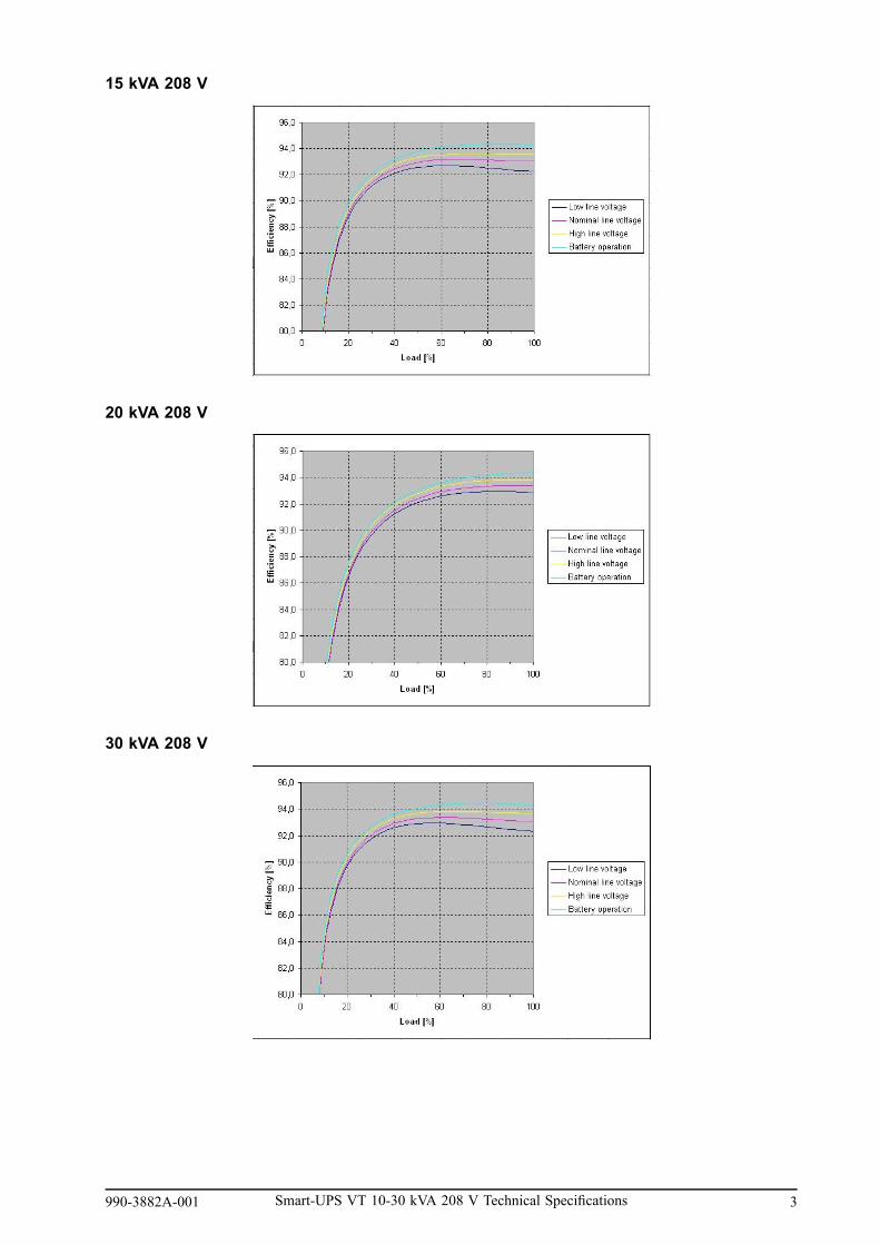
15 kVA 208 V
20 kVA 208 V
30 kVA 208 V
990-3882A-001 Smart-UPS VT 10-30 kVA 208 V Technical Specifications 3

Derating due to Load Power Factor
Batteries
Efficiency DC to AC
10 kVA 15 kVA 20 kVA 30 kVA
208 V 220V 208 V 220V 208 V 220V 208 V 220V
Efficiency atnominal batt.voltage (%)
94.3 94.4 94.3 94.4 94.3 94.4 94.3 94.4
Battery Run-Times - APC Battery Solution
“Bat. shelves” indicates the total number of populated battery shelves in the UPS and Battery Enclosure.
10 kVA 208 V Typical Performances
Load kVA
# of batteryshelves
1 2 4 6 8 10
1 110 53 23 13 9 6
2 258 128 58 35 24 18
4 Smart-UPS VT 10-30 kVA 208 V Technical Specifications 990-3882A-001

Load kVA
# of batteryshelves
1 2 4 6 8 10
3 422 210 97 60 42 31
4 597 298 138 86 61 46
5 781 390 182 113 80 61
6 973 487 227 142 101 77
7 1172 586 274 172 122 93
8 1376 689 322 202 144 110
9 1586 794 372 233 167 128
10 1800 901 422 265 189 145
11 2019 1011 474 298 213 163
12 2241 1123 526 331 237 182
13 2468 1236 580 365 261 200
14 2697 1352 634 399 286 219
15 2931 1468 689 434 310 239
16 3167 1587 745 469 336 258
17 3406 1707 801 505 361 278
18 3648 1829 858 541 387 298
19 3893 1951 916 577 413 318
20 4140 2075 975 614 440 339
21 4390 2201 1034 652 467 359
22 4642 2327 1093 689 494 380
23 4897 2455 1153 727 521 401
24 5154 2584 1214 765 548 422
25 5413 2714 1275 804 576 444
26 5674 2845 1337 843 604 465
15 kVA 208 V Typical Performances
990-3882A-001 Smart-UPS VT 10-30 kVA 208 V Technical Specifications 5

Load kVA
# of batteryshelves
1 3 6 9 12 15
1 n.a. n.a. n.a. n.a. n.a. n.a.
2 258 81 35 21 14 10
3 422 134 60 36 25 18
4 597 191 86 52 36 27
5 781 251 113 70 49 37
6 973 314 142 88 62 47
7 1172 378 172 106 75 57
8 1376 444 202 125 88 67
9 1586 512 233 145 102 78
10 1800 582 265 165 117 89
11 2019 653 298 185 131 100
12 2241 725 331 206 146 112
13 2468 799 365 227 161 123
14 2697 873 399 249 177 135
15 2931 949 434 270 192 147
16 3167 1026 469 292 208 159
17 3406 1103 505 315 224 171
18 3648 1182 541 337 240 184
19 3893 1261 577 360 256 196
20 4140 1342 614 383 273 209
21 4390 1423 652 407 290 222
22 4642 1505 689 430 306 235
23 4897 1587 727 454 323 248
24 5154 1671 765 478 341 261
25 5413 1755 804 502 358 274
26 5674 1840 843 526 375 288
20 kVA 208 V Typical Performances
6 Smart-UPS VT 10-30 kVA 208 V Technical Specifications 990-3882A-001

Load kVA
# of batteryshelves
2 4 8 12 16 20
1 n.a. n.a. n.a. n.a. n.a. n.a.
2 117 55 24 14 9 6
3 193 92 41 24 16 12
4 274 132 59 36 25 18
5 359 174 78 48 33 25
6 448 217 99 61 42 32
7 540 262 119 74 52 39
8 634 308 141 87 61 46
9 731 355 163 101 71 54
10 830 404 185 115 81 62
11 931 453 208 129 91 70
12 1034 503 231 144 102 78
13 1138 554 255 159 113 86
14 1244 606 279 174 123 94
15 1352 659 303 189 134 103
16 1461 712 328 205 145 111
17 1572 766 353 220 157 120
18 1684 821 378 236 168 129
19 1797 876 404 252 180 137
20 1911 932 430 269 191 146
21 2027 988 456 285 203 155
22 2143 1045 482 302 215 165
23 2261 1103 509 318 227 174
24 2379 1161 536 335 239 183
25 2499 1219 563 352 251 193
26 2620 1278 590 369 263 202
27 2741 1338 618 387 276 211
28 2864 1397 645 404 288 221
990-3882A-001 Smart-UPS VT 10-30 kVA 208 V Technical Specifications 7

30 kVA 208 V Typical Performances
Load kVA
# of batteryshelves
2 6 12 18 24 30
1 n.a. n.a. n.a. n.a. n.a. n.a.
2 n.a. n.a. n.a. n.a. n.a. n.a.
3 193 58 24 14 9 6
4 274 83 36 21 14 10
5 359 110 48 29 19 14
6 448 138 61 36 25 18
7 540 166 74 45 31 23
8 634 196 87 53 37 27
9 731 226 101 61 43 32
10 830 257 115 70 49 37
11 931 289 129 79 55 42
12 1034 321 144 88 62 47
13 1138 354 159 98 69 52
14 1244 387 174 107 75 57
15 1352 421 189 117 82 62
16 1461 455 205 126 89 68
17 1572 489 220 136 96 73
18 1684 524 236 146 103 78
19 1797 560 252 156 110 84
20 1911 596 269 166 117 89
21 2027 632 285 176 125 95
22 2143 668 302 187 132 101
23 2261 705 318 197 140 106
24 2379 742 335 208 147 112
25 2499 780 352 218 155 118
26 2620 817 369 229 162 124
8 Smart-UPS VT 10-30 kVA 208 V Technical Specifications 990-3882A-001
Load kVA
# of batteryshelves
2 6 12 18 24 30
27 2741 855 387 240 170 130
28 2864 894 404 251 178 136
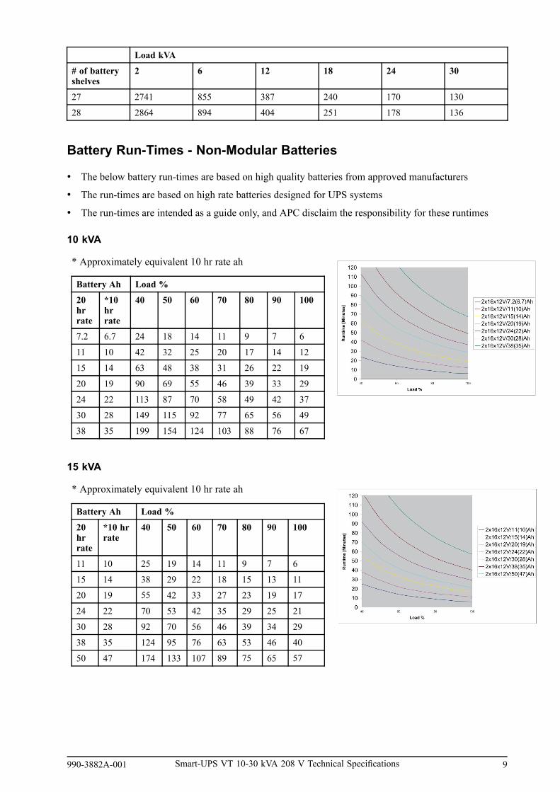
Battery Run-Times - Non-Modular Batteries
• The below battery run-times are based on high quality batteries from approved manufacturers
• The run-times are based on high rate batteries designed for UPS systems
• The run-times are intended as a guide only, and APC disclaim the responsibility for these runtimes
10 kVA
* Approximately equivalent 10 hr rate ah
Battery Ah Load %
20hrrate
*10hrrate
40 50 60 70 80 90 100
7.2 6.7 24 18 14 11 9 7 6
11 10 42 32 25 20 17 14 12
15 14 63 48 38 31 26 22 19
20 19 90 69 55 46 39 33 29
24 22 113 87 70 58 49 42 37
30 28 149 115 92 77 65 56 49
38 35 199 154 124 103 88 76 67
15 kVA
* Approximately equivalent 10 hr rate ah
Battery Ah Load %
20hrrate
*10 hrrate
40 50 60 70 80 90 100
11 10 25 19 14 11 9 7 6
15 14 38 29 22 18 15 13 11
20 19 55 42 33 27 23 19 17
24 22 70 53 42 35 29 25 21
30 28 92 70 56 46 39 34 29
38 35 124 95 76 63 53 46 40
50 47 174 133 107 89 75 65 57
990-3882A-001 Smart-UPS VT 10-30 kVA 208 V Technical Specifications 9

20 kVA
* Approximately equivalent 10 hr rate ah
Battery Ah Load %
20hrrate
*10hrrate
40 50 60 70 80 90 100
15 14 26 19 15 12 10 8 7
20 19 39 29 23 18 15 13 11
24 22 49 37 29 24 20 17 14
30 28 65 49 39 32 27 23 20
38 35 88 67 53 44 37 31 27
50 47 123 94 75 62 52 45 39
65 60 170 130 104 86 73 63 55
30 kVA
* Approximately equivalent 10 hr rate ah
Battery Ah Load %
20hrrate
*10hrrate
40 50 60 70 80 90 100
24 22 29 21 17 13 11 9 7
30 28 39 29 23 18 15 13 11
38 35 53 40 31 26 21 18 15
50 47 75 57 45 37 31 27 23
65 60 104 79 63 52 44 38 33
80 74 135 103 82 68 57 49 43
100 93 178 136 109 90 76 66 57
Battery Discharge Current
10 kVA 15 kVA 20 kVA 30 kVA
I bat @ Vbatnominal, 100% load
22 33 44 66
I bat @ Vbat min,100% load
28 41 55 83
I bat @ Vbat min,150% load
40 62 83 125
End of Discharge Voltage at 100% Load
Note: The voltage is 1.6 to 1.75 per cell depending on load.
10 Smart-UPS VT 10-30 kVA 208 V Technical Specifications 990-3882A-001

Note: C equals Idischarge divided by the battery Ah capacity.
Battery Gassing Rates
10–15 kVA
Note: We recommend that room ventilation is based on maximum values.
Gassing rate cc/hr (ml/hr)Battery position # of bat shelves
Typical Max
UPS 1 24 48
UPS 2 48 96
XR1 3 72 144
XR1 4 96 192
XR1 5 120 240
XR1 6 144 288
XR1 7 168 336
XR1 8 192 384
XR2 9 216 432
XR2 10 240 480
XR2 11 264 528
XR2 12 288 576
XR2 13 312 624
XR2 14 336 672
XR3 15 360 720
XR3 16 384 768
XR3 17 408 816
XR3 18 432 864
XR3 19 456 912
990-3882A-001 Smart-UPS VT 10-30 kVA 208 V Technical Specifications 11

Gassing rate cc/hr (ml/hr)Battery position # of bat shelves
Typical Max
XR3 20 480 960
XR4 21 504 1008
XR4 22 528 1056
XR4 23 552 1104
XR4 24 576 1152
XR4 25 600 1200
XR4 26 624 1248
20–30 kVA
Note: We recommend that room ventilation is based on maximum values.
Gassing rate cc/hr (ml/hr)Battery position # of bat shelves
Typical Max
UPS 1 24 48
UPS 2 48 96
UPS 3 72 144
UPS 4 96 192
XR1 5 120 240
XR1 6 144 288
XR1 7 168 336
XR1 8 192 384
XR1 9 216 432
XR1 10 240 480
XR2 11 264 528
XR2 12 288 576
XR2 13 312 624
XR2 14 336 672
XR2 15 360 720
XR2 16 384 768
XR3 17 408 816
XR3 18 432 864
XR3 19 456 912
XR3 20 480 960
XR3 21 504 1008
XR3 22 528 1056
XR4 23 552 1104
XR4 24 576 1152
XR4 25 600 1200
XR4 26 624 1248
XR4 27 648 1296
12 Smart-UPS VT 10-30 kVA 208 V Technical Specifications 990-3882A-001

Gassing rate cc/hr (ml/hr)Battery position # of bat shelves
Typical Max
XR4 28 672 1344
XR4 28 672 1344
Electrolyte Values for SYBTU1–PLP
Battery module String of batteries (Four batterymodules)
Electrolyte volume L (gal) 2.78 (0.72) 11.14 (2.87)
Electrolyte weight kg (lbs) 3.72 (8.18) 14.86 (32.73)
Sulfuric acid volume L (gal) 0.89 (0.23) 3.54 (0.91)
Sulfuric acid weight kg (lbs) 1.62 (3.57) 6.48 (14.27)
Battery Material Safety Data Sheet
Note: For Material Safety Data Sheet (MSDS), go to“http://nam-en.apc.com/app/answers/detail/a_id/564/kw/msds“.
Communication and Management
Network Management Card
The system is equipped with one network management card for remote monitoring and control of anindividual UPS by connecting it directly to the network.
A.Network Management Card
990-3882A-001 Smart-UPS VT 10-30 kVA 208 V Technical Specifications 13

Input and Output Contacts
Pins 7 and 8 are for external charge control. When 7 and 8 are closed, the UPS charges batteries witha pre-defined percentage (0-25-50-75-100%) of the maximum charging power. To be used in generatorapplications, or if special codes require control of charging.
Pins 5 and 6 are for external maintenance bypass Q3 (auxiliary switch N/C type). When Q3 is closed,signals are fed back to the UPS controller.
Pins 1 to 4 are for battery measurement (only applicable to APC XR Battery Enclosures).
Pin Description
8 External charging control return
7 External control of charging
6 Q3 active return
5 Q3 active
4 Battery measurement supply1
3 Battery unit quantity 1
2 Maximum battery temperature 1
1 Battery measurement return 1
1 To be used with APC XR BatteryEnclosure.
14 Smart-UPS VT 10-30 kVA 208 V Technical Specifications 990-3882A-001

EPO in Single SystemsConnect the EPO cable using one of the following four wiring configurations.
Note: Use only 1-1½ mm² copper wire for the connection of the Emergency Power Off(EPO) and other optional equipment.
Note: The UPS must be connected to either a dry contact or a 24 VDC EPO (EmergencyPower Off) switch.
Note: The external EPO +24 VDC, 1500 mA circuit can be supplied through other vendors.
1. Dry Contacts Normally Open: EPO isactivated when pin 1 is connected to pins 3 and5. Connections: 2-4-6, 3-5, and 1 (NormallyOpen).
2. +24 V Normally Open: EPO is activated whenan isolated SELV 24 VDC voltage is suppliedon pin 1 with reference to pin 2. Connections:3-5 and 4-6.
3. Dry Contacts Normally Closed: EPO isactivated when a connection from pin 3 to 5 isopened. Connections: 4-6.
4. +24 V Normally Closed: EPO is activatedwhen a SELV 24 VDC voltage is removed frompin 3 with reference to pin 4.
990-3882A-001 Smart-UPS VT 10-30 kVA 208 V Technical Specifications 15

EPO in Parallel SystemsIn parallel systems each UPS unit must have its own dry contact (voltage free) connected to J108. Thedrawing below shows a “Normally Closed” installation of three UPS units in parallel.
WARNING: For parallel and separate systems with common EPO, each UPS unit mustbe connected to a separate dry contact.
WARNING: Parallel EPO wiring between more UPS units can result in critical UPSmalfunctioning.
ComplianceDirectives for CEmarking
89/336/EDC73/237/EEC
Safety EN/IEC62040-1-1UL1778
EMC EN50091-2/IEC62040-2FCC15A
Performance EN/IEC62040-3
Electromagneticcompatibility (EMC)
EN/IEC 61000-4-2 level 3, performance criteria AEN/IEC 61000-4-3 level 2,performance criteria AEN/IEC 61000-4-4 level 2, performance criteria AEN/IEC61000-4-5 level 3, performance criteria A
16 Smart-UPS VT 10-30 kVA 208 V Technical Specifications 990-3882A-001

Facility Planning
AC Input Specifications10 kVA 15 kVA 20 kVA 30 kVA
208 V 220 V 208 V 220 V 208 V 220 V 208 V 220 V
Connection type 4-wire (3PH + N + G)
Input frequency(Hz)
40-70
I thd < 5% at full load
Nom input current(A)
24.3 23.0 36.6 34.6 48.6 45.8 73.2 69.0
Max input current(A)
26.7 25.2 40.2 38.0 53.0 50.1 80.1 75.8
Input currentlimitation (A)
32.8 32.8 49.5 49.5 65.2 65.2 98.8 98.8
Input power factorcorrection
> 0.98 at load > 50%
Maximum ShortCircuit Withstand(kA)
30
AC Bypass Input Specifications10 kVA 15 kVA 20 kVA 30 kVA
208 V 220 V 208 V 220 V 208 V 220 V 208 V 220 V
Connection type 4-wire (3PH + N + G)
Input frequency(Hz)
50 +/- 10 or 60 +/- 10
Nom input current(A)
27.8 26.2 41.6 39.4 55.5 52.5 83.3 78.7
990-3882A-001 Smart-UPS VT 10-30 kVA 208 V Technical Specifications 17

AC Output Specifications10 kVA 15 kVA 20 kVA 30 kVA
208 V 220 V 208 V 220 V 208 V 220 V 208 V 220 V
Connection type 4-wire (3PH + N + G)
Overload capacity 150% for 1 minute (normal operation)125% for 10 minutes (normal operation)150% for 1 minute (battery operation)125% for 10 minutes (battery operation)110% continuous (bypass operation)800% for 500 ms (bypass operation)
Voltage tolerance 160-240 V for 208 V systems160-253 V for 220 V systems
Nom outputcurrent (A)
27.8 26.2 41.6 39.4 55.5 52.5 83.3 78.7
Output frequency(sync to mains)
50 Hz ±0.1 Hz, ±3 Hz, ±10 Hz60 Hz ±0.1 Hz, ±3 Hz, ±10 Hz
Slew rate (Hz/Sec) 0.25-1
Total HarmonicDistortion (THD)
< 1.5% linear< 3.5% non-linear
Load power factor 0.5 leading to 0.5 lagging
Dynamic loadresponse
± 5%
Output voltageregulation
± 1%
Battery SpecificationsType VRLA
Nominal voltage (VDC) +/- 192
Float voltage (VDC) +/- 219
End of discharge voltage (VDC) +/- 154
Battery current (at full load) 66.5 A at +/-192 V
Max. current (at end of discharge) 83.2 A at + 154 V
Max. charging power 10 kVA: 1600 W15 kVA: 2400 W20 kVA: 3200 W30 kVA: 3200 W
Typical re-charge time 5 hours
End voltage 1.6-1.75 V/cell (automatic, depending on load)
18 Smart-UPS VT 10-30 kVA 208 V Technical Specifications 990-3882A-001

Recommended Cable Sizes
WARNING: At 100% switch mode load, the neutral must be rated for 200% phasecurrent.
Caution: All wiring must comply with all applicable national and/or electrical code.
Note: The recommended cable sizes are based on an environment with an ambienttemperature of 30° C (86° F).
10 kVA 15 kVA 20 kVA 30 kVA
Utility/mains input 8 AWG 6 AWG 4 AWG 1 AWG
Static bypass input 8 AWG 6 AWG 4 AWG 1 AWG
DC input 1 AWG 1 AWG 1 AWG 1 AWG
Output 8 AWG 6 AWG 4 AWG 1 AWG
Connection Terminals
Cable size (AWG) Cable lug type Crimping tool Die Terminal boltdiameter
12 YA12CL2TC38 MD7-34R W12CVT 6 mm (0.2 in)
8 YA8CL2TC38 MD7-34R W8CVT 6 mm (0.2 in)
6 YA6CL2TC38 MD7-34R W6CVT 6 mm (0.2 in)
4 YA4CL2TC38 MD7-34R W4CVT 6 mm (0.2 in)
1 YA1CL2TC38 MD7-34R W1CVT 6 mm (0.2 in)
Torque Specifications
The power wiring should be torqued to 7 Nm (45 lbf-in).
990-3882A-001 Smart-UPS VT 10-30 kVA 208 V Technical Specifications 19

Fuses and Breakers
Single Utility/Mains System
• Q1: Utility/mains input• Q2: UPS output• Q3: Manual bypass• MBS: Mechanical bypass switch
Dual Utility/Mains System
• Q1: Utility/mains input• Q2: UPS output• Q3: Manual bypass• Q5: Static bypass input• MBS: Mechanical bypass switch
20 Smart-UPS VT 10-30 kVA 208 V Technical Specifications 990-3882A-001
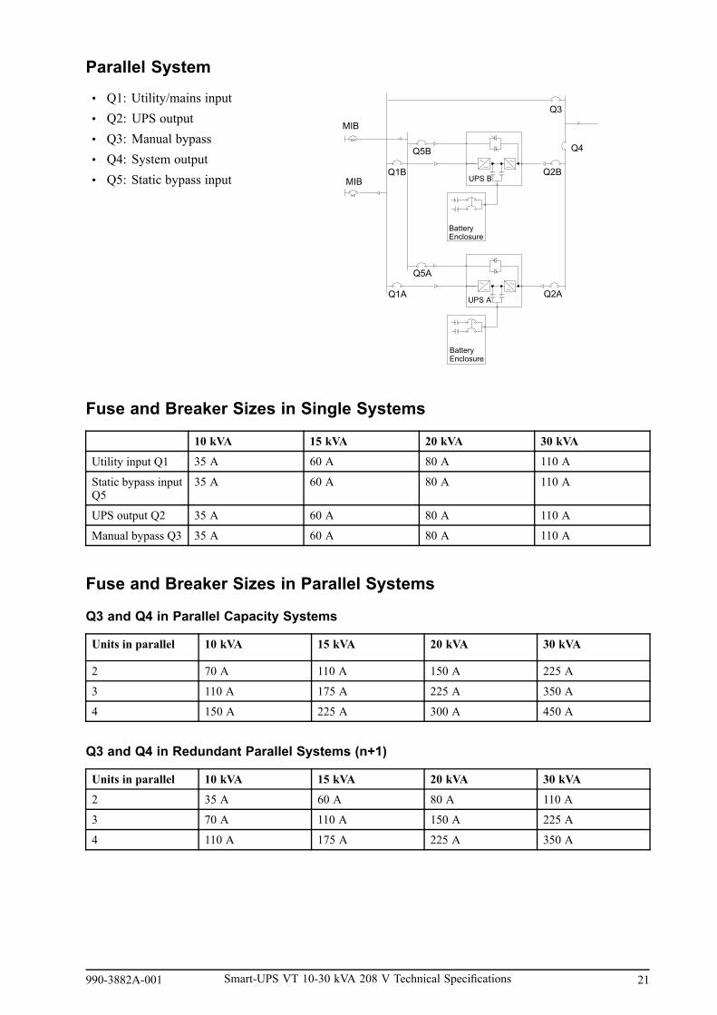
Parallel System
• Q1: Utility/mains input• Q2: UPS output• Q3: Manual bypass• Q4: System output• Q5: Static bypass input
Fuse and Breaker Sizes in Single Systems
10 kVA 15 kVA 20 kVA 30 kVA
Utility input Q1 35 A 60 A 80 A 110 A
Static bypass inputQ5
35 A 60 A 80 A 110 A
UPS output Q2 35 A 60 A 80 A 110 A
Manual bypass Q3 35 A 60 A 80 A 110 A
Fuse and Breaker Sizes in Parallel Systems
Q3 and Q4 in Parallel Capacity Systems
Units in parallel 10 kVA 15 kVA 20 kVA 30 kVA
2 70 A 110 A 150 A 225 A
3 110 A 175 A 225 A 350 A
4 150 A 225 A 300 A 450 A
Q3 and Q4 in Redundant Parallel Systems (n+1)
Units in parallel 10 kVA 15 kVA 20 kVA 30 kVA
2 35 A 60 A 80 A 110 A
3 70 A 110 A 150 A 225 A
4 110 A 175 A 225 A 350 A
990-3882A-001 Smart-UPS VT 10-30 kVA 208 V Technical Specifications 21

Minimum Breaker Settings
800% overloadbypassoperation
150% overloadnormal/batteryoperation
125% overloadnormal/batteryoperation
Continuously
Duration 500 ms 60 s 10 min
Mains input -1 - - 34 A
Static bypassinput
223 A - - 31 A
10 kVA
UPS output 223 A 42 A 35 A 31 A
Mains input -1 - - 51 A
Static bypassinput
333 A - - 46 A
15 kVA
UPS output 333 A 63 A 52 A 46 A
Mains input -1 - - 68 A
Static bypassinput
444 A - - 62 A
20 kVA
UPS output 444 A 84 A 70 A 62 A
Mains input -1 - - 99 A
Static bypassinput
667 A - - 92 A
30 kVA
UPS output 667 A 125 A 105 A 92 A1 For single mains systems, use the higher value of mains and static bypass
Physical
Weights and Dimensions
ModelkVA
SKU number Weight kg (lbs) Height mm (in) Width mm (in) Depth mm (in)
SUVTP10KF1B2S 305 (671) 1499 (59) 356 (14) 813 (32.01)
SUVTP10KF1B4S 323.18 (712) 1499 (59) 523 (20.6) 813 (32.01)
SUVTP10KF2B2S 396.82 (873) 1499 (59) 356 (14) 813 (32.01)
SUVTP10KF2B4S 415 (913) 1499 (59) 523 (20.6) 813 (32.01)
SUVTP10KF3B4S 506.82 (1115) 1499 (59) 523 (20.6) 813 (32.01)
10 kVA
SUVTP10KF4B4S 599.09 (1318) 1499 (59) 523 (20.6) 813 (32.01)
SUVTP15KF2B2S 396.82 (873) 1499 (59) 356 (14) 813 (32.01)
SUVTP15KF2B4S 415 (913) 1499 (59) 523 (20.6) 813 (32.01)
SUVTP15KF3B4S 506.82 (1115) 1499 (59) 523 (20.6) 813 (32.01)
15 kVA
SUVTP15KF4B4S 599.09 (1318) 1499 (59) 523 (20.6) 813 (32.01)
SUVTP20KF2B4S 445 (979) 1499 (59) 523 (20.6) 813 (32.01)
SUVTP20KF3B4S 536.82 (1181) 1499 (59) 523 (20.6) 813 (32.01)
20 kVA
SUVTP20KF4B4S 629.09 (1384) 1499 (59) 523 (20.6) 813 (32.01)
SUVTP30KF3B4S 536.82 (1181) 1499 (59) 523 (20.6) 813 (32.01)30 kVA
SUVTP30KF4B4S 629.09 (1384) 1499 (59) 523 (20.6) 813 (32.01)
22 Smart-UPS VT 10-30 kVA 208 V Technical Specifications 990-3882A-001

Shipping Weights and Dimensions
ModelkVA
SKU number Weight kg (lbs) Height mm (in) Width mm (in) Depth mm (in)
SUVTP10KF1B2S 335.92 (739) 1643 (64.7) 650 (25.6) 1062 (41.8)
SUVTP10KF1B4S 354.09 (78) 1643 (64.7) 650 (25.6) 1062 (41.8)
SUVTP10KF2B2S 427.73 (941) 1643 (64.7) 650 (25.6) 1062 (41.8)
SUVTP10KF2B4S 445.91 (983) 1643 (64.7) 650 (25.6) 1062 (41.8)
SUVTP10KF3B4S 537.73 (1183) 1643 (64.7) 650 (25.6) 1062 (41.8)
10 kVA
SUVTP10KF4B4S 630 (1386) 1643 (64.7) 650 (25.6) 1062 (41.8)
SUVTP15KF2B2S 428.18 (942) 1643 (64.7) 650 (25.6) 1062 (41.8)
SUVTP15KF2B4S 445.91 (981) 1643 (64.7) 650 (25.6) 1062 (41.8)
SUVTP15KF3B4S 537.73 (1183) 1643 (64.7) 650 (25.6) 1062 (41.8)
15 kVA
SUVTP15KF4B4S 630 (1386) 1643 (64.7) 650 (25.6) 1062 (41.8)
SUVTP20KF2B4S 475.91 (1047) 1643 (64.7) 650 (25.6) 1062 (41.8)
SUVTP20KF3B4S 568.18 (1252) 1643 (64.7) 650 (25.6) 1062 (41.8)
20 kVA
SUVTP20KF4B4S 660 (1452) 1643 (64.7) 650 (25.6) 1062 (41.8)
SUVTP30KF3B4S 568.18 (1250) 1643 (64.7) 650 (25.6) 1062 (41.8)30 kVA
SUVTP30KF4B4S 660 (1452) 1643 (64.7) 650 (25.6) 1062 (41.8)
990-3882A-001 Smart-UPS VT 10-30 kVA 208 V Technical Specifications 23

Clearance
Note: Clearance dimensions are published for airflow and service access only. Consult withthe local safety codes and standards for additional requirements in your local area.
EnvironmentalOperating Temperature 0 - 40 °C (32-104 ºF)
Storage Temperature with batteries -15 - 40 °C (-5-113 ºF)Batteries can only be stored for a longer period if theyare fully charged. Fully charged batteries can be storedfor up to 12 months at temperatures up to 25 °C and upto 6 month at temperatures from 25 °C to 45 °C withoutbeing recharged.
Storage Temperature without batteries -30 - 70 °C (-22-158 ºF)
Operating Relative Humidity 0 - 95%, non-condensing
Storage Relative Humidity 0 - 95%, non-condensing
Operating Elevation 0-1000 m: 100% load1000–1500 m: 95% load1500–2000 m: 91% load2000–2500 m: 86% load2500–3000 m: 82% load
Storage Elevation 0-15000 meters (0-50000 ft )
Audible noise at 70% load – 1 meter from surface of unit 10–15 kVA: 42.3 dBA20–30 kVA: 46.2 dBA
Audible noise at 100% load – 1 meter from surface ofunit
10-20 kVA: 51.3 dBA30 kVA: 55.0 dBA
Protection Class Up to IP51
Colour Dark grey
24 Smart-UPS VT 10-30 kVA 208 V Technical Specifications 990-3882A-001

Heat Dissipation
Model (kVA) Heat dissipation (BTU/hr)
10 kVA batteries fully charged 1938.00
10 kVA batteries charging 2211.00
15 kVA batteries fully charged 2989.00
15 kVA batteries charging 3398.00
20 kVA batteries fully charged 4238.00
20 kVA batteries charging 4852.00
30 kVA batteries fully charged 5896.00
30 kVA batteries charging 6715.00
990-3882A-001 Smart-UPS VT 10-30 kVA 208 V Technical Specifications 25
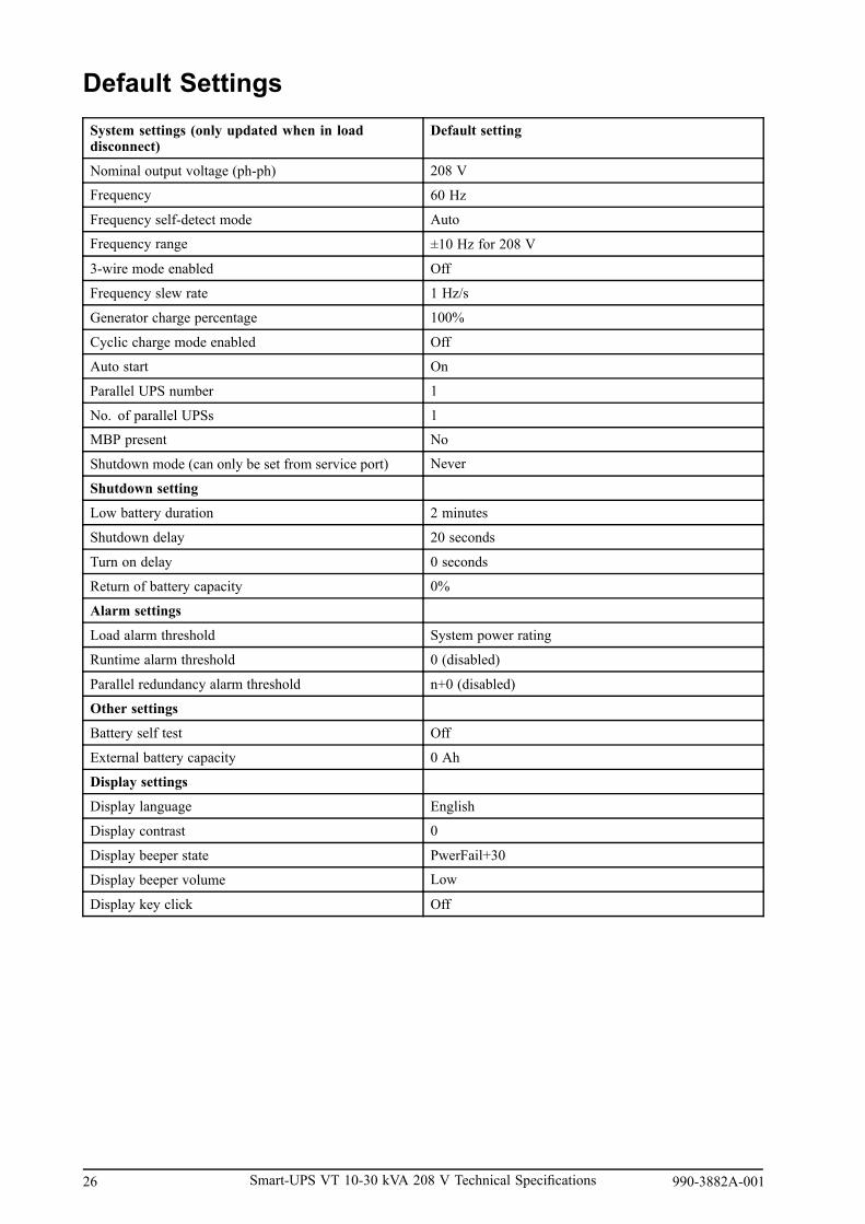
Default SettingsSystem settings (only updated when in loaddisconnect)
Default setting
Nominal output voltage (ph-ph) 208 V
Frequency 60 Hz
Frequency self-detect mode Auto
Frequency range ±10 Hz for 208 V
3-wire mode enabled Off
Frequency slew rate 1 Hz/s
Generator charge percentage 100%
Cyclic charge mode enabled Off
Auto start On
Parallel UPS number 1
No. of parallel UPSs 1
MBP present No
Shutdown mode (can only be set from service port) Never
Shutdown setting
Low battery duration 2 minutes
Shutdown delay 20 seconds
Turn on delay 0 seconds
Return of battery capacity 0%
Alarm settings
Load alarm threshold System power rating
Runtime alarm threshold 0 (disabled)
Parallel redundancy alarm threshold n+0 (disabled)
Other settings
Battery self test Off
External battery capacity 0 Ah
Display settings
Display language English
Display contrast 0
Display beeper state PwerFail+30
Display beeper volume Low
Display key click Off
26 Smart-UPS VT 10-30 kVA 208 V Technical Specifications 990-3882A-001
Drawings
Note: A comprehensive set of drawings is available on the engineering website atwww.engineer.apc.com.
Note: These drawings are for reference ONLY — subject to change without notice.
990-3882A-001 Smart-UPS VT 10-30 kVA 208 V Technical Specifications 27

Single Feed without MBP
28 Smart-UPS VT 10-30 kVA 208 V Technical Specifications 990-3882A-001

990-3882A-001 Smart-UPS VT 10-30 kVA 208 V Technical Specifications 29

Dual Feed without MBP
30 Smart-UPS VT 10-30 kVA 208 V Technical Specifications 990-3882A-001

990-3882A-001 Smart-UPS VT 10-30 kVA 208 V Technical Specifications 31
Options
Hardware Options
Battery Systems
APC Smart-UPS VT Extended Run Frame, w/Breaker, 2 Batt. Modules Exp. to 6,and 5x8 Startup Service
SUVTBXR2B6S
APC Smart-UPS VT Extended Run Enclosure, w/Breaker, 6 Battery Modules and5x8 Startup Service
SUVTBXR6B6S
APC Smart-UPS VT Extended Run Frame w/2 Batt. Modules Exp. to 6 and 5x8Startup Service
SUVTXR2B6S
APC Smart-UPS VT Extended Run Enclosure w/6 Batt. Modules and 5x8 StartupService
SUVTXR6B6S
Battery Module for Symmetra PX, Smart-UPS VT or Galaxy 3500 SYBT4
Management Cards and Options
SMARTSLOT EXPANSION CHASSIS AP9600APC SmartSlot Triple Chassis Black AP9604BLKModbus/Jbus Interface Card AP9622UPS Network Management Card 2 AP9630UPS Network Management Card 2 with Environmental Monitoring AP9631UPS Network Management Card w/ Environmental Monitoring & Out of BandManagement
AP9618
Interface Cables
UPS Communications Cable Simple Signalling 940-0020UPS Communication Cable Smart Signalling 940-0024UPS Communications Cable Smart Signalling 15' / 4.5m AP980415'/5m Extension Cable for use w/ UPS communications cable AP9815UNIX BASIC SIGNALING CABLE AP9823Isolate Serial Extension Cable AP9825UPS Communication Cable for IBM AS/400 940–0006Cisco Unity Express UPS Simple Signalling Cable AP9840
Mounting Accessories
APC Smart-UPS VT Battery Lock Kit for 1 Batt. Module SUVTOPT003
APC Smart-UPS VT Baying Kit, 14inch/351mm UPS Enclosure to XR SUVTOPT004
APC Smart-UPS VT Baying Kit, 20inch/523mm UPS Enclosure to XR SUVTOPT005
32 Smart-UPS VT 10-30 kVA 208 V Technical Specifications 990-3882A-001

APC Smart-UPS VT Baying Kit, XR to XR SUVTOPT006
APC Smart-UPS VT Parallel Operation Baying Kit SUVTOPT011
Service Bypass Panels
APC Maintenance Bypass Panel 10-15kVA 208V Wallmount SBPSU10K15F-WPAPC Maintenance Bypass Panel 20-30kVA 208V Wallmount SBPSU20K30F-WPAPC Smart-UPS VT Maintenance Bypass Panel 10-30kVA 208V Wall Mount w/42Pos. Distribution Panel
SBPSU10K30FC1M1-WP
APC Smart-UPS VT Maintenance Bypass Cabinet 10-15kVA 208V Floormount SUVTSBP10K15FAPC Smart-UPS VT Maint. Bypass Cabinet 10-30kVA 208V Floormount with 42Position Distribution Panel
SUVTSBP10K30F-DP
APC Smart-UPS VT Maintenance Bypass Cabinet 20-30kVA 208V Floormount SUVTSBP20K30FAPC Smart-UPS VT Parallel Maintenance Bypass, up to 3 units 10-15kVA 208VFloormount
SUVTSBPAR10K15F
APC Smart-UPS VT Parallel Maintenance Bypass, up to 3 units 20-30kVA 208VFloormount
SUVTSBPAR20K30F
APC Smart-UPS VT Parallel Maintenance Bypass Kit SUVTOPT010
Smart-UPS Accessories
APC Smart-UPS VT Input Transformer 208/208 10-30kVA Floormount SUVTXFM10K30FAPC Smart-UPS VT Input Transformer 480/208 10-30kVA Floormount SUVTXFM10K30GAPC Smart-UPS VT Input Transformer MCCB 480/208 10-30kVA Floormount SUVTSBPXFM10K30GAPC Smart-UPS VT Input Transformer MCCB 208/208 10-30kVA Floormount SUVTSBPXFM10K30FAPC Smart-UPS VT Battery Temperature Sensor for External Battery Cabinet SUVTOPT007
APC Smart-UPS VT Parallel Communications Kit SUVTOPT009
APC Smart-UPS VT Parallel Communications Kit, including Installation SUVTOPT009S
APC Smart-UPS VT Subfeed Distribution 208V, (5) L21-20 & (1) 50A HW output SUVTOPT104
APC Smart-UPS VT Subfeed Distribution 208V, (5) L21-20 & (1) 63A HW output SUVTOPT105
APC Smart-UPS VT Input Breaker for 20kVA/208V UPS SUVTOPT112
APC Smart-UPS VT Input Breaker for 30kVA/208V UPS SUVTOPT113
APC Smart-UPS VT Input Breaker for 20kVA 480/208V UPS SUVTOPT114
APC Smart-UPS VT Input Breaker for 30kVA 480/208V UPS SUVTOPT115
990-3882A-001 Smart-UPS VT 10-30 kVA 208 V Technical Specifications 33

Parallel Capabilities
Paralleling Capabilities
• Up to four UPS units paralleled for capacity
• Up to four UPS units paralleled for redundancy (n+1)
• Communication between parallel units via the Parallel Communication Box
A1A
A.ParallelCommunicationBox
34 Smart-UPS VT 10-30 kVA 208 V Technical Specifications 990-3882A-001

APC by Schneider Electric LimitedFactory Warranty
Three Phase Power Products or Cooling SolutionsOne-Year Factory WarrantyThe limited warranty provided by APC by Schneider Electric (APC®) in this Statement of LimitedFactory Warranty applies only to products you purchase for your commercial or industrial use in theordinary course of your business.
Terms of WarrantyAmerican Power Conversion warrants that the product shall be free from defects in materials andworkmanship for a period of one year from the date of product start-up when start-up is performedby APC authorized service personnel and occurs within six months of The APC shipment date. Thiswarranty covers repairing or replacing any defective parts including on-site labor and travel. In theevent that the product fails to meet the foregoing warranty criteria, the warranty covers repairing orreplacing defective parts at the sole discretion of APC for a period of one year from the shipment date.For APC cooling solutions, this warranty does not cover circuit breaker resetting, loss of refrigerant,consumables, or preventive maintenance items. Repair or replacement of a defective product or partthereof does not extend the original warranty period. Any parts furnished under this warranty may benew or factory-remanufactured.
Non-transferable WarrantyThis warranty is extended to the first person, firm, association or corporation (herein referred to by“You” or “Your”) for whom the APC product specified herein has been purchased. This warranty is nottransferable or assignable without the prior written permission of APC.
Assignment of WarrantiesAPC will assign you any warranties which are made by manufacturers and suppliers of components ofthe APC product and which are assignable. Any such warranties are assigned “AS IS” and APC makesno representation as to the effectiveness or extent of such warranties, assumes no responsibility for anymatters which may be warranted by such manufacturers or suppliers and extends no coverage under thisWarranty to such components.
Drawings, DescriptionsAPC warrants for the warranty period and on the terms of the warranty set forth herein that theAPC product will substantially conform to the descriptions contained in the APC Official PublishedSpecifications or any of the drawings certified and agreed to by contract with APC if applicable thereto(“Specifications”). It is understood that the Specifications are not warranties of performance and notwarranties of fitness for a particular purpose.
ExclusionsAPC shall not be liable under the warranty if its testing and examination disclose that the alleged defect inthe product does not exist or was caused by end user or any third person misuse, negligence, improper
990-3882A-001 Smart-UPS VT 10-30 kVA 208 V Technical Specifications 35

installation or testing. Further APC shall not be liable under the warranty for unauthorized attempts torepair or modify wrong or inadequate electrical voltage or connection, inappropriate on-site operationconditions, corrosive atmosphere, repair, installation, start-up by non-APC designated personnel, a changein location or operating use, exposure to the elements, Acts of God, fire, theft, or installation contraryto APC recommendations or specifications or in any event if the APC serial number has been altered,defaced, or removed, or any other cause beyond the range of the intended use.
THERE ARE NO WARRANTIES, EXPRESS OR IMPLIED, BY OPERATION OF LAW OROTHERWISE, OF PRODUCTS SOLD, SERVICED OR FURNISHED UNDER THIS AGREEMENTOR IN CONNECTION HEREWITH. APC DISCLAIMS ALL IMPLIED WARRANTIES OFMERCHANTABILITY, SATISFACTION AND FITNESS FOR A PARTICULAR PURPOSE. APCEXPRESS WARRANTIES WILL NOT BE ENLARGED, DIMINISHED, OR AFFECTED BY ANDNO OBLIGATION OR LIABILITY WILL ARISE OUT OF, APC RENDERING OF TECHNICAL OROTHER ADVICE OR SERVICE IN CONNECTION WITH THE PRODUCTS. THE FOREGOINGWARRANTIES AND REMEDIES ARE EXCLUSIVE AND IN LIEU OF ALL OTHER WARRANTIESAND REMEDIES. THE WARRANTIES SET FORTH ABOVE CONSTITUTE APC SOLE LIABILITYAND PURCHASER’S EXCLUSIVE REMEDY FOR ANY BREACH OF SUCH WARRANTIES.APC WARRANTIES RUN ONLY TO PURCHASER AND ARE NOT EXTENDED TO ANY THIRDPARTIES.
IN NO EVENT SHALL APC, ITS OFFICERS, DIRECTORS, AFFILIATES OR EMPLOYEESBE LIABLE FOR ANY FORM OF INDIRECT, SPECIAL, CONSEQUENTIAL OR PUNITIVEDAMAGES, ARISING OUT OF THE USE, SERVICE OR INSTALLATION, OF THE PRODUCTS,WHETHER SUCH DAMAGES ARISE IN CONTRACT OR TORT, IRRESPECTIVE OF FAULT,NEGLIGENCE OR STRICT LIABILITY OR WHETHER APC HAS BEEN ADVISED IN ADVANCEOF THE POSSIBILITY OF SUCH DAMAGES, SPECIFICALLY, APC IS NOT LIABLE FOR ANYCOSTS, SUCH AS LOST PROFITS OR REVENUE, LOSS OF EQUIPMENT, LOSS OF USE OFEQUIPMENT, LOSS OF SOFTWARE, LOSS OF DATA, COSTS OF SUBSTITUANTS, CLAIMS BYTHIRD PARTIES, OR OTHERWISE.
NO SALESMAN, EMPLOYEE OR AGENT OF APC IS AUTHORIZED TO ADD TO OR VARY THETERMS OF THIS WARRANTY. WARRANTY TERMS MAY BE MODIFIED, IF AT ALL, ONLY INWRITING SIGNED BY AN APC OFFICER AND LEGAL DEPARTMENT.
Warranty ClaimsCustomers with warranty claims issues may access the APC worldwide customer support networkthrough the APC web site: “http://www.apc.com/support/contact/“. Select your country from the countryselection pull-down menu. Open the Support tab at the top of the web page to obtain contact informationfor customer support in your region.
36 Smart-UPS VT 10-30 kVA 208 V Technical Specifications 990-3882A-001

990-3882A-001 Smart-UPS VT 10-30 kVA 208 V Technical Specifications 37

Worldwide Customer Support
Customer support is available at no charge via e-mail or telephone. Contact information is available atwww.apc.com/support/contact
© APC by Schneider Electric. APC and the APC logo are owned by Schneider Electric IndustriesS.A.S., American Power Conversion Corporation, or their affiliated companies. All other trademarksare property of their respective owners.
990-3882A-001 11/2011


![[XLS] · Web view400 630 630 400 630 990 990 630 630 630 630 990 990 990 990 990 990 400 400 990 630 990 630 630 400 990 990 990 990 990 630 630 990 990 630 630 990 990 990 990 990](https://static.documents.pub/doc/80x56/5af695027f8b9a5b1e8f4d8f/xls-view400-630-630-400-630-990-990-630-630-630-630-990-990-990-990-990-990-400.jpg)

