i. About Manual MTYCUI01—On-Site Control Connections for Milnor® Automated Laundering System Machines and Controllers This manual supplements the system installation drawings provided with most Milnor automated laundering systems. It is intended for use by the technician involved in electrically interfacing the machines and controllers (MultiTrac™, Miltrac™, Drynet, Mildata®) in such a system (see Note 1). Some of the information provided in this manual is repeated in the reference and schematic manuals for the respective devices.
Note 1: The various system controllers and data collectors that serve Milnor automated laundering systems continue to evolve to take advantage of developments in PC technology. The “MultiTrac Overview”, included as a supplement to this manual, describes these products, as of this writing.
i. 1. Scope This manual addresses the commonly required on-site control connections, but not all on-site wiring for Milnor automated laundering systems, as explained below.
i. 1.1. Electric Power Connections—Incoming power connections, which should be made only by a qualified electrician, are not covered in this manual. Refer to the installation drawings for approximate locations of connection points for incoming electrical power. Refer to the installation drawings, the machine nameplates, and manual MAEFUSE1AE “External Fuse and Wire Sized for Milnor Machines” for voltage and fusing requirements. Refer to the device schematic manuals and electric box tags for power terminal identification.
i. 1.2. Cabling Fabricated By Milnor—Milnor supplies the cabling for standard interconnections between closely positioned devices as well as for machine components shipped separately. Although some electrical interconnection information may be provided in the installation and/or schematic manuals for the device, instructions are often not needed because the cabling is:
• pre-fabricated—All needed cabling is bundled (in flexible conduit, festooning, etc.) and cut to size.
• pre-attached to one device—One end of the cable is attached and pre-wired. • plug-together—The free end of the cable and the device it attaches to have mating
connectors pre-wired. • tagged—Where conductors could be mis-matched, these are tagged and/or color coded to
identify matching components.
Preface
PELLERIN MILNOR CORPORATION
i. 1.3. Cabling Fabricated On Site—For interconnected devices that are not closely positioned, the cable routing cannot be determined in advance. This cabling must be fabricated and completely wired on site. It may also be preferable to obtain the cable material locally. This manual covers most such interconnection requirements and provides cable material specifications. However, if one or more of the devices in the system will be non-Milnor (allied device), a special means of communicating with the allied device, called an allied interface, is required. With the exception of the special CBW-to-centrifugal extractor interface mentioned below, allied interfaces are not covered herein. Refer to manual MTPALI01—“Allied Interfaces for Milnor Automated Laundering System Machines (Mark 5 Controls and Later).” for a complete explanation. This manual categorizes the cabling fabricated and installed on site as follows: 1. Subsystem connections—These are connections between separately installed devices needed
for the device(s) to function, irrespective of the overall system. The cabling to be fabricated can include wiring for serial communication, 120VAC face plate controls, machine functions, and three-phase motor power. The following categories of subsystem connections are covered: a. Dryers and shuttles—Certain machine controls are located on equipment separate from
the machines themselves. b. Dryvac (Autolint®) systems—which require connections between the Dryvac unit and the
dryers they serve. c. No-dry station—which requires connections between the no-dry discharge allowed switch
and the dryers the no-dry station serves. d. Device Master, PC Device Master, Linear Costa, and Linear Costa Master—which
require connections between these controllers and the devices (primarily conveyors) they control.
e. CBW® / centrifugal extractor—In systems with a CBW and a centrifugal extractor, these devices exchange certain data via allied interface signals, even though they both communicate with Miltrac.
2. System connections (serial links)—Miltrac, Drynet (dryer/shuttle controller), and Mildata each communicate with the devices within their networks via a permanently installed, serial communication cable. The procedures for fabricating and installing this cable are the same for each type of network (see Note 2).
Note 2: Although unlikely, an individual machine in an automated laundering system may also use an external serial link to print data to a dedicated printer or download data to a Milnor serial memory storage device or to other machines. The serial cables used for these purposes are described in document BICWUC01 “Construction of External Serial Link Cables”, included as a supplement to this manual.
3. PC Networking—Increasingly, the various PCs used in Milnor automated laundering systems (e.g., Mentor, Mildata, MultiTrac) are being networked to share data and resources.
Currently, the following product types and special conditions requiring on-site wiring are not covered in this manual. Contact Milnor Technical Support for assistance:
• Vertsto—This controller is used to control vertical storage conveyors and has connection requirements similar to the Device Master, PC Device Master, Linear Costa, and Linear Costa Master controllers.
• Miltrac Loader Controller (Front End Loader)—On-site connection information for this controller is provided in reference manual MTYCFR01 “Miltrac Loader Controller (Front End Loader).”
Preface
PELLERIN MILNOR CORPORATION
• Shuttle Call—A relay logic controller typically used to control the sequence in which a bank of washer-extractors discharge to a shuttle. The connections between the controller and each device must be wired on site.
• Discharge Sequencer—A relay logic controller typically used to control the sequence in which a bank of dryers discharge to a common belt. The connections between the controller and each device must be wired on site.
• Connections needed when loading multi-cake dryers with a single cake shuttle (see Milnor document MSIN0913AE).
i. 2. How to Identify this Manual and its Included Documents [Document BIUUUD13] Use the specifications on the front cover of this manual to identify this manual or the included documents. This section tells about these specifications. Published manual number—The primary identification number for the manual. Specified date—The first assembly date for the machine or change about which this manual
gives data. As-of date—The company makes new manuals about items that are not new. These new manuals
will include data started before this date. Access date—The date Milnor prepared the manual for its publication. Depth—“Detail” manuals show the maximum available data. “Synopsis” manuals show the
minimum necessary data. A manual with more data goes with a synopsis manual. Custom—A value of “n/a” here shows that this manual applies to all machines identified on the
inner front cover of the manual. Other values show the laundry name and a code for the specified machine.
Applicability—Each value here shows the machines or model numbers that this manual applies to. The inner front cover shows the full list of the applicable models. If this value is “not used,” this manual has a different function.
Language Code—The value here shows the language and dialect of this manual. “Eng01” shows that the manual uses United States English.
Refer to a document in this manual with all of the specifications shown on the front cover. Replace the published manual number with the document number.
i. 3. Trademarks of Pellerin Milnor Corporation [Document BIUUUD14] These words are trademarks of Pellerin Milnor Corporation:
ii. Contacting Milnor® Your authorized Milnor dealer can assist you with your Milnor machine and knows about the local conditions that may be pertinent to the installation, use, or maintenance of the machine. Contact your dealer first. For assistance from the Milnor factory, refer to Table 2 for contact information.
Table 2: Pellerin Milnor Corporation Contact Information Purpose Department Telephone FAX E-mail/Website
Ask about, comment on, or report an error in equipment manuals
Technical Publications
504-712-7636 504-469-1849 [email protected] Your first contact with any question should be your authorized Milnor dealer, but problems or special situations may require consultation with the Milnor factory. Mail written correspondence to this address:
Table of Contents Sections Figures, Tables, and Supplements
Preface
i. About Manual MTYCUI01—On-Site Control Connections for Milnor® Automated Laundering System Machines and Controllers (Document BIYCUI01)
i.1. Scope i.1.1. Electric Power Connections i.1.2. Cabling Fabricated By Milnor i.1.3. Cabling Fabricated On Site
i.2. How to Identify this Manual and its Included Documents (Document BIUUUD13)
i.3. Trademarks of Pellerin Milnor Corporation (Document BIUUUD14)
Table 1: Trademarks
ii. Contacting Milnor® (Document BIUUUK06) Table 2: Pellerin Milnor Corporation Contact Information
Table of Contents
Chapter 1. Subsystem Connections
1.1. On-Site Control Connections for Dryers With Mark 5 Controls (Document BICDUI01)
Table 3: Summary of Dryer On-Site Control Connections
Supplement 1: How a Dryer-controlled No-dry Works
1.1.1. On-Site Control Connections for a Stand-alone Dryer 1.1.2. On-Site Control Connections for Dryers in a Miltrac™
System With a Central Controls Mounting Panel (Belt Box) (Document BICDUI02)
Table 4: Dryer On-Site Control Connections in Systems with a Belt Box
1.1.3. On-Site Control Connections for Dryers in a Drynet (dryer/shuttle controller) or MultiTrac™ System (Document BICDUI03)
Table 5: Dryer On-Site Control Connections In Drynet and MultiTrac Systems
1.2. On-Site Control Connections for Dryvac (Autolint®) Units Serving Dryers With Mark 5 Controls (Document BICDUI04)
1.2.1. Connections for Sequencer 3 (DRYVAC01) Table 6: Sequencer 3 Connections When Dryvac Serves Stand-alone Dryers or Dryers in a Drynet or MultiTrac System
Table 7: Sequencer 3 Connections When Dryvac Serves Dryers In a Miltrac System With a Belt Box
Table of Contents
PELLERIN MILNOR CORPORATION
Sections Figures, Tables, and Supplements
1.2.2. Connections for Sequencer 5 (DRYVAC02) Table 8: Sequencer 5 Connections When Dryvac Serves Stand-alone Dryers or Dryers In a Drynet or MultiTrac System
Table 9: Sequencer 5 Connections When Dryvac Serves Dryers In a Miltrac System With a Belt Box
1.3. On-Site Control Connections for Shuttles With Mark 5 Controls (Document BICSUI01)
Figure 1: Shuttle On-Site Connection Points for Various Shuttle and System Types
1.3.1. Conductor Set “A” (see Figure 1) Table 10: Shuttle (control box)-To-Shuttle Controller Connections (in belt box or dedicated controller box)
1.3.3. Conductor Set “C” (see Figure 1) 1.3.3.1. C1-to-C2: Shuttle-to-Festoon Box (Milnor-supplied
Festoon Cable)
1.3.3.2. C3-to-C4: Festoon Box-to-Shuttle Control Box (Milnor-supplied Cable)
1.3.4. About the Controls for Stand-alone, Elevating Shuttles 1.3.4.1. Stand-alone Shuttle Controls Mounted on the Shuttle
Frame
1.3.4.2. Stand-alone Shuttle Controls Located Remotely
1.4. On-Site Control Connections for Device Master, PC Device Master, Linear Costa, and Linear Costa Master (Document BIYCDI01)
1.4.1. On-Site Control Connections for Device Master, Linear Costa, or Linear Costa Master in a Miltrac™ System (Document BIYCDI02)
Table 12: Standard On-Site Control Connections for Device Master, Linear Costa, and Linear Costa Master in Systems With a Miltrac Belt Box
1.4.2. On-Site Control Connections for PC Device Master in a MultiTrac™ System (Document BIYCDI03)
Table 13: Device Master On-Site Control Connections in MultiTrac Systems
1.5. Special Load Interface Requirements for the Milnor® Centrifugal Extractor (Document BICXUI01)
1.5.1. When the Devices Communicate Via Miltrac
Table of Contents
PELLERIN MILNOR CORPORATION
Sections Figures, Tables, and Supplements
1.5.2. When Devices Do Not Communicate Via Miltrac 1.5.2.1. Enabling Allied Data Pass 1.5.2.2. Batch Data 1.5.2.3. Using Drycode for Extract Code on Certain CBW's 1.5.2.4. The Empty Load Signal 1.5.2.5. The End Extract (Early Call) and Start Extractor
Signals
1.5.2.6. The Start Cycle Signal 1.5.2.7. The Extractor Says Load Allowed Signal
Chapter 2. System Connections (Serial Links)
2.1. How Milnor® System Machines and Fully Programmable Washer-Extractors Use Serial Communication (Document BICCUC02)
2.2. On-Site Installation and Troubleshooting of Permanent Serial Communication Cables (Document BICCUC01)
2.2.1. “Daisy Chain” Versus “Home Run” Wiring 2.2.2. Specifications and Requirements
2.2.2.1. Cable Specifications 2.2.2.2. Conduit Requirements 2.2.2.3. Grounding the Controllers 2.2.2.4. Grounding the Shield and Unused Wires
2.2.2.4.1. If the “Home Run” Method Is Used 2.2.2.4.2. If the “Daisy Chain” Method Is Used
2.2.3. Connecting the Serial Link To Subordinate Devices (Machines)
2.2.3.1. Identifying Serial Ports Table 14: Serial Port Dedicated Uses Figure 2: Serial Ports on Processor Board
2.2.3.2. Wiring the Serial Low and Serial High Lines 2.2.4. Connecting the Serial Link to the System Controller
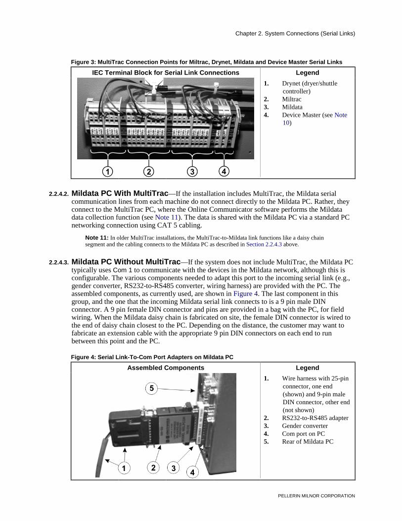
Figure 3: MultiTrac Connection Points for Miltrac, Drynet, Mildata and Device Master Serial Links
2.2.4.2. Mildata PC With MultiTrac 2.2.4.3. Mildata PC Without MultiTrac Figure 4: Serial Link-To-Com Port
Adapters on Mildata PC 2.2.4.4. Older Drynet (Dryer/Shuttle) Controller 2.2.4.5. Older Miltrac Controller
2.2.5. Troubleshooting Reminders for the “Daisy Chain” Method
Chapter 3. PC Networking
Table of Contents
PELLERIN MILNOR CORPORATION
Sections Figures, Tables, and Supplements
3.1. Networking the PC's used in CBW® Systems (Document BIYDUI01)
3.1.1. What Types of Data are Shared Over the LAN? 3.1.2. LAN Architecture, Protocol, and Topology 3.1.3. Computer Identification for Networking Table 15: Computer Identification Values
for PC's in a CBW System (see Notice 5 )
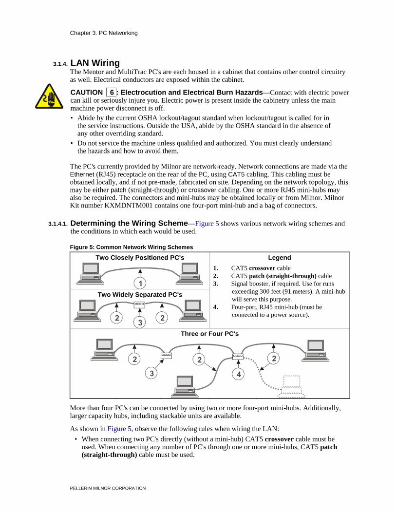
3.1.4. LAN Wiring 3.1.4.1. Determining the Wiring Scheme Figure 5: Common Network Wiring
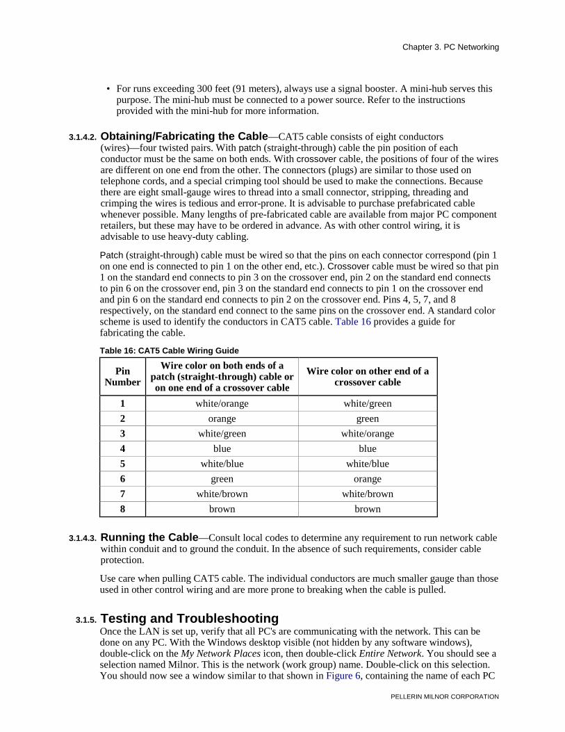
Schemes 3.1.4.2. Obtaining/Fabricating the Cable Table 16: CAT5 Cable Wiring Guide 3.1.4.3. Running the Cable
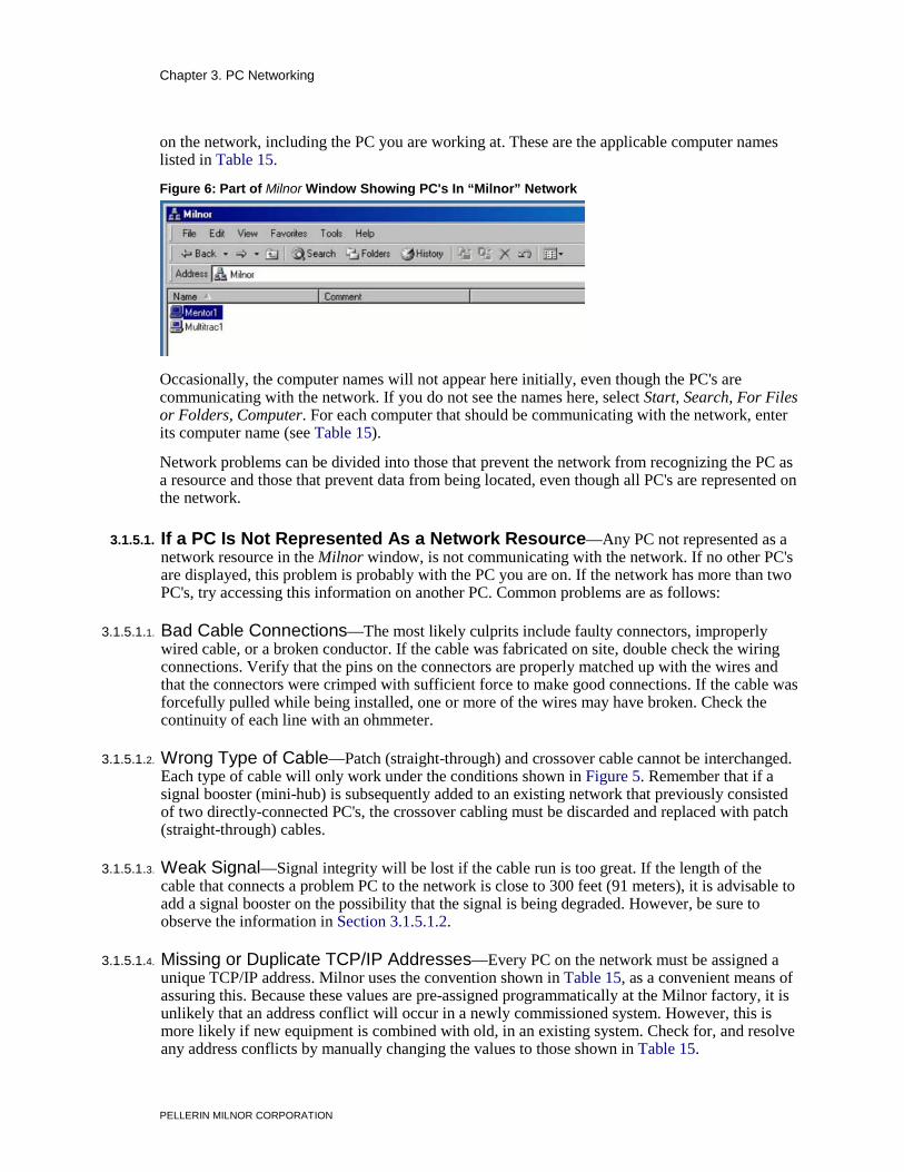
3.1.5. Testing and Troubleshooting Figure 6: Part of Milnor Window Showing PC's In “Milnor” Network
3.1.5.1. If a PC Is Not Represented As a Network Resource 3.1.5.1.1. Bad Cable Connections 3.1.5.1.2. Wrong Type of Cable 3.1.5.1.3. Weak Signal 3.1.5.1.4. Missing or Duplicate TCP/IP Addresses
3.1.5.2. If Data Is Not Locatable 3.1.5.2.1. File or Program Deleted 3.1.5.2.2. Invalid Computer Name 3.1.5.2.3. Mismatched Port Addresses In Online
Communicator and Mentor
3.1.5.2.4. Mismatched Port Addresses in Online Communicator and Mildata Client (Older Systems)
3.1.6. Sharing a Printer Over the Network
Chapter 4. Supplemental Information
4.1. MultiTrac™ Overview (Document BIYDTF01) 4.1.1. MultiTrac Functional Components 4.1.2. The MultiTrac User Interface 4.1.3. MultiTrac As a Controller
4.2. Construction of External Serial Link Cables (Document BICWUC01)
4.2.1. Pin Identification Figure 7: 9-Pin DIN Connector Pin Identification (from wire entry side of connectors)
Table 17: External Serial Link Pin Assignments
4.2.2. How to Wire the Cables 4.2.2.1. Cable Specifications
Table of Contents
PELLERIN MILNOR CORPORATION
Sections Figures, Tables, and Supplements
4.2.2.2. Connecting a Machine to a Printer for “Print Data” Figure 8: Wiring Diagram for Cable to Connect a Machine to a Printer
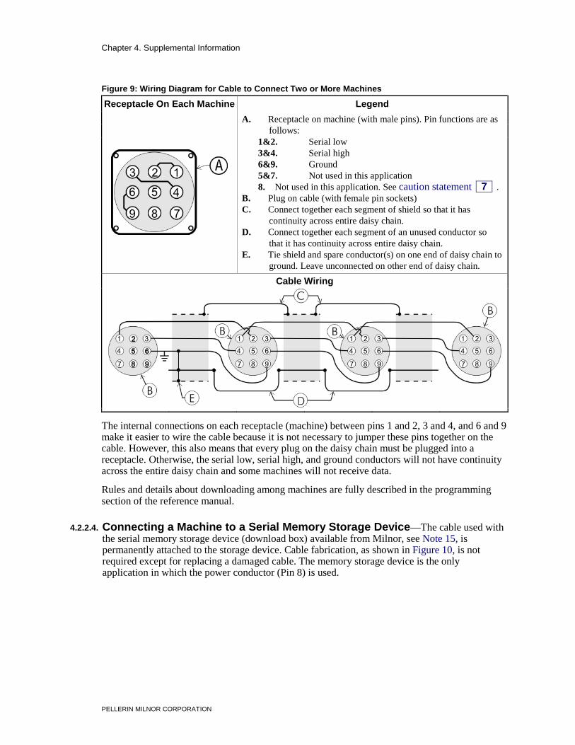
4.2.2.3. Connecting Two or More Machines for Machine-to-machine Transfer
Figure 9: Wiring Diagram for Cable to Connect Two or More Machines
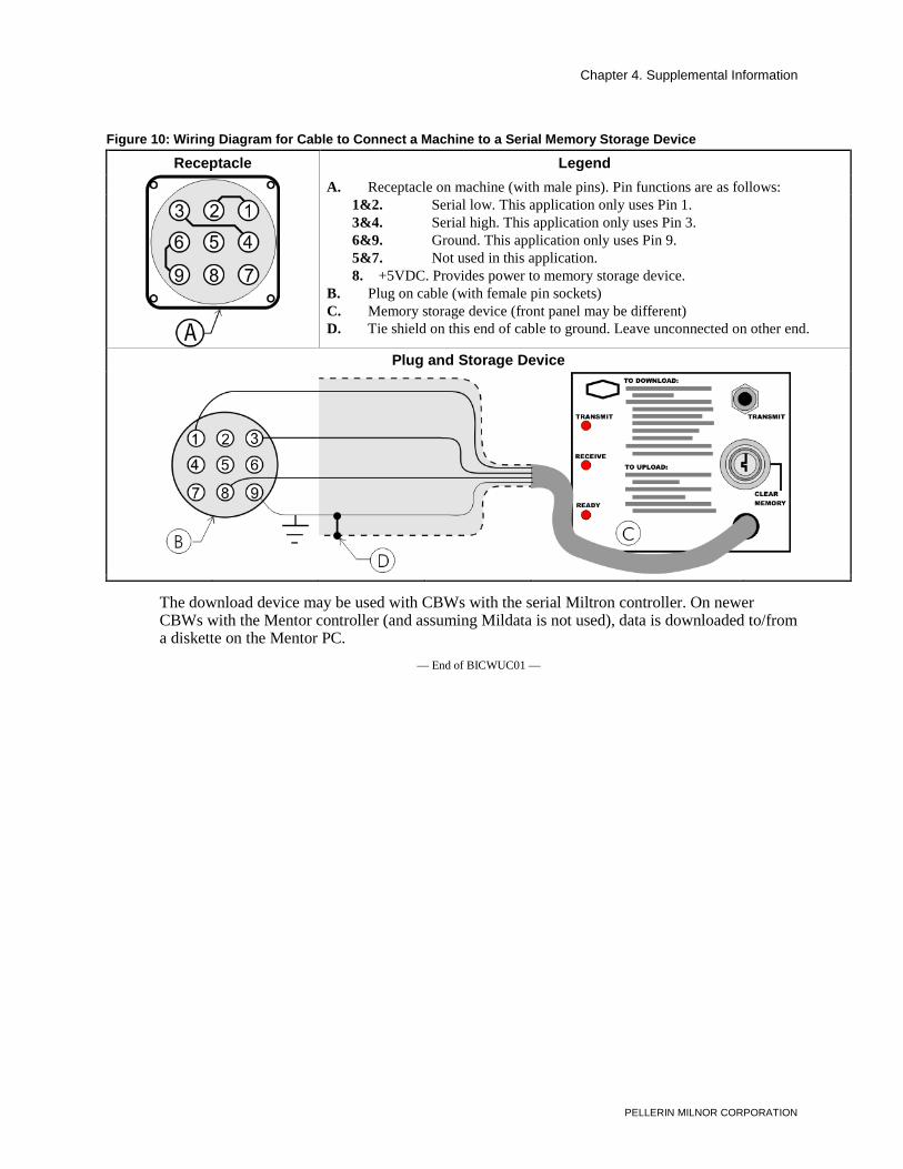
4.2.2.4. Connecting a Machine to a Serial Memory Storage Device
Figure 10: Wiring Diagram for Cable to Connect a Machine to a Serial Memory Storage Device
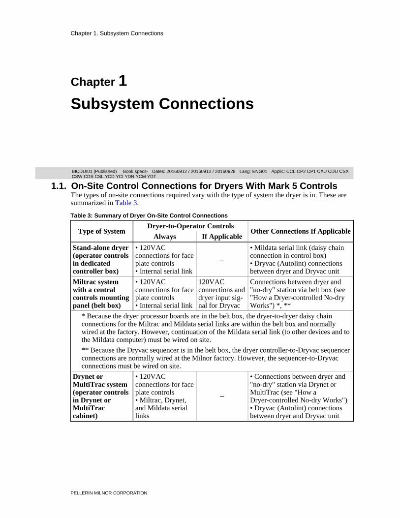
1.1. On-Site Control Connections for Dryers With Mark 5 Controls The types of on-site connections required vary with the type of system the dryer is in. These are summarized in Table 3.
Table 3: Summary of Dryer On-Site Control Connections
Type of System Dryer-to-Operator Controls Other Connections If Applicable Always If Applicable
Stand-alone dryer (operator controls in dedicated controller box)
• 120VAC connections for face plate controls • Internal serial link
--
• Mildata serial link (daisy chain connection in control box) • Dryvac (Autolint) connections between dryer and Dryvac unit
Miltrac system with a central controls mounting panel (belt box)
• 120VAC connections for face plate controls • Internal serial link
120VAC connections and dryer input sig- nal for Dryvac
Connections between dryer and "no-dry" station via belt box (see "How a Dryer-controlled No-dry Works") *, **
* Because the dryer processor boards are in the belt box, the dryer-to-dryer daisy chain connections for the Miltrac and Mildata serial links are within the belt box and normally wired at the factory. However, continuation of the Mildata serial link (to other devices and to the Mildata computer) must be wired on site.
** Because the Dryvac sequencer is in the belt box, the dryer controller-to-Dryvac sequencer connections are normally wired at the Milnor factory. However, the sequencer-to-Dryvac connections must be wired on site.
Drynet or MultiTrac system (operator controls in Drynet or MultiTrac cabinet)
• 120VAC connections for face plate controls • Miltrac, Drynet, and Mildata serial links
--
• Connections between dryer and "no-dry" station via Drynet or MultiTrac (see "How a Dryer-controlled No-dry Works") • Dryvac (Autolint) connections between dryer and Dryvac unit
Chapter 1. Subsystem Connections
PELLERIN MILNOR CORPORATION
Supplement 1
How a Dryer-controlled No-dry Works
If the installation includes a dryer-controlled no-dry station, every dryer that is configured to control a no-dry station must know if the no-dry station is available to receive the batch. This is accomplished via a Discharge Allowed switch at the no-dry station that makes an input on all dryers that are so-configured. It is convenient to run the dryer-to-Discharge Allowed switch conductors via the the belt box, Drynet cabinet, or MultiTrac cabinet. This permits bundling these conductors with other control conductors that run between the dryer and the central control cabinet and running a single cable between the cabinet and the Discharge Allowed switch.
1.1.1. On-Site Control Connections for a Stand-alone Dryer In this configuration, Milnor will normally provide a length of flexible conduit suitable for locating the dedicated dryer controller box near the dryer. Typically, some connections will be made at the factory and some will need to be made on site. For example, if a dedicated Milnor elevating shuttle (for loading the dryer) is to be supplied with the dryer, the dryer controller box is usually mounted to the shuttle frame at the factory. The factory will also provide the flexible conduit already attached to the control box and the wiring already connected on this end. The other end of the conduit will have pre-wired mating connectors. On site, the conduit need only be secured to the dryer and the connectors plugged together. The dryer-to-operator controls connections are the same as described in Section 1.1.2 “On-Site Control Connections for Dryers in a Miltrac™ System With a Central Controls Mounting Panel (Belt Box)”. If the dryers use a Milnor Dryvac (Autolint) system, see Section 1.2. “On-Site Control Connections for Dryvac (Autolint®) Units Serving Dryers With Mark 5 Controls”.
1.1.2. On-Site Control Connections for Dryers in a Miltrac™ System With a Central Controls Mounting Panel (Belt Box) [Document BICDUI02] In this configuration, a remote dryer controller (one for each dryer in the system), which contains the dryer processor board, is located in the belt box. This supports the keypad, display and other operator controls (e.g., Master switch) also mounted on the belt box. The dryer connections that must be made on site are listed in Table 4. The connection points may be on terminal blocks or mating connectors. The mating connector and pins to be wired are normally provided in a bag located in the control box or cabinet.
Chapter 1. Subsystem Connections
PELLERIN MILNOR CORPORATION
Table 4: Dryer On-Site Control Connections in Systems with a Belt Box
Purpose Cable Specification
Connection Point
On Dryer On Dryer
Con-troller in Belt Box
Connector Pin Connector Pin Required Connections Between Dryer and Operator Controls in Belt Box
Earth ground One conductor: 14AWG (2.5mm²) with 600VAC insulation
TBA 6 TBA 6 (ground terminal) (ground terminal)
120VAC face plate controls -- All except 6458TG1x models
Multi-conductor cable: 18AWG (1.0mm²) with 300VAC color coded insulation. Ground unused wires on one end only.
Two-conductor shielded cable: 18AWG (1.0mm²) twisted pair with 300VAC color coded insulation and 85% braided shield. Ground shield one end only.
TBA 106 1MTA33 1 or 2
(serial link #2 low)
TBA 107 1MTA33 3 or 4
(serial link #2 high) Additional Connections, If Applicable
Processor input/ground for "no-dry"
On Dryer At No-dry Station Two-conductor shielded cable. Run all cables via the belt box. In belt box, "common" the corresponding wires from all dryers together and ground shields.
TBA 140 "Discharge Allowed"
switch
N/O
TBA 7 C
Miltrac and Mildata serial links
See document BICCUC01 "On-Site Installation and Troubleshooting of Permanent Serial Communication Cables" for a complete explanation.
Dryvac Controls
See document BICDUI04 "Dryer-To-Dryvac (Autolint) Connections" for a complete explanation.
Chapter 1. Subsystem Connections
PELLERIN MILNOR CORPORATION
1.1.3. On-Site Control Connections for Dryers in a Drynet (dryer/shuttle controller) or MultiTrac™ System [Document BICDUI03] In this configuration, each dryer processor board is located on its respective dryer and a control box containing the Master switch ( m/ M), Stop button ( 0), and Start button ( 1) for each dryer is mounted on the Drynet or MultiTrac cabinet. The dryer connections that must be made on-site are listed in Table 5. The connection points may be on terminal blocks or mating connectors. The mating connector and pins to be wired are normally provided in a bag located in the control box or cabinet.
Table 5: Dryer On-Site Control Connections In Drynet and MultiTrac Systems
Purpose Cable Specification
Connection Point On Dryer
On Drynet or MultiTrac
Connector Pin Connector Pin Required Connections Between Dryer and Drynet or MultiTrac Cabinet
Earth ground One conductor: 14AWG (2.5mm²) with 600VAC insulation
TBA 6 TBA 6 (ground terminal) (ground terminal)
120VAC face plate controls -- All except 6458TG1x models
Multi-conductor cable: 18AWG (1.0mm²) with 300VAC color coded insulation. Ground unused wires on one end only.
Miltrac serial link See document BICCUC01 "On-Site
Installation and Troubleshooting of Permanent Serial Communication Cables" for a complete explanation.
1MTA32 1 or 2 Miltrac SRL 1MTA32 3 or 4 Miltrac SRH
Drynet serial link
1MTA29 1 or 2 Drynet SRL 1MTA29 3 or 4 Drynet SRH
Mildata serial link
1MTA34 1 or 2 Mildata SRL 1MTA34 3 or 4 Mildata SRH
Additional Connections, If Applicable
Processor input/ground for "no-dry"
On Dryer At No-dry Station Two-conductor shielded cable. Run all cables via the Drynet or MultiTrac cabinet. In cabinet, "common" the corresponding wires from all dryers together and ground shields.
TBA 140 "Discharge Allowed"
switch
N/O
TBA 7 C
Dryvac controls
See document BICDUI04 "Dryer-To-Dryvac (Autolint) Connections" for a complete explanation.
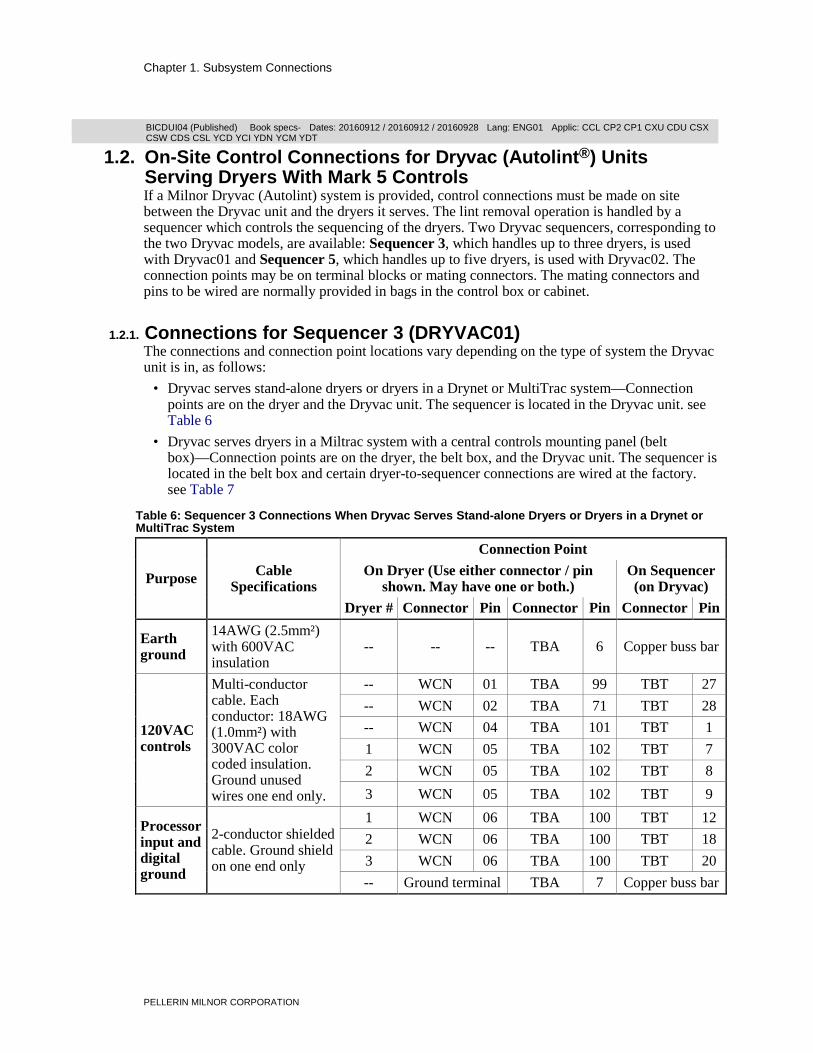
1.2. On-Site Control Connections for Dryvac (Autolint®) Units Serving Dryers With Mark 5 Controls If a Milnor Dryvac (Autolint) system is provided, control connections must be made on site between the Dryvac unit and the dryers it serves. The lint removal operation is handled by a sequencer which controls the sequencing of the dryers. Two Dryvac sequencers, corresponding to the two Dryvac models, are available: Sequencer 3, which handles up to three dryers, is used with Dryvac01 and Sequencer 5, which handles up to five dryers, is used with Dryvac02. The connection points may be on terminal blocks or mating connectors. The mating connectors and pins to be wired are normally provided in bags in the control box or cabinet.
1.2.1. Connections for Sequencer 3 (DRYVAC01) The connections and connection point locations vary depending on the type of system the Dryvac unit is in, as follows:
• Dryvac serves stand-alone dryers or dryers in a Drynet or MultiTrac system—Connection points are on the dryer and the Dryvac unit. The sequencer is located in the Dryvac unit. see Table 6
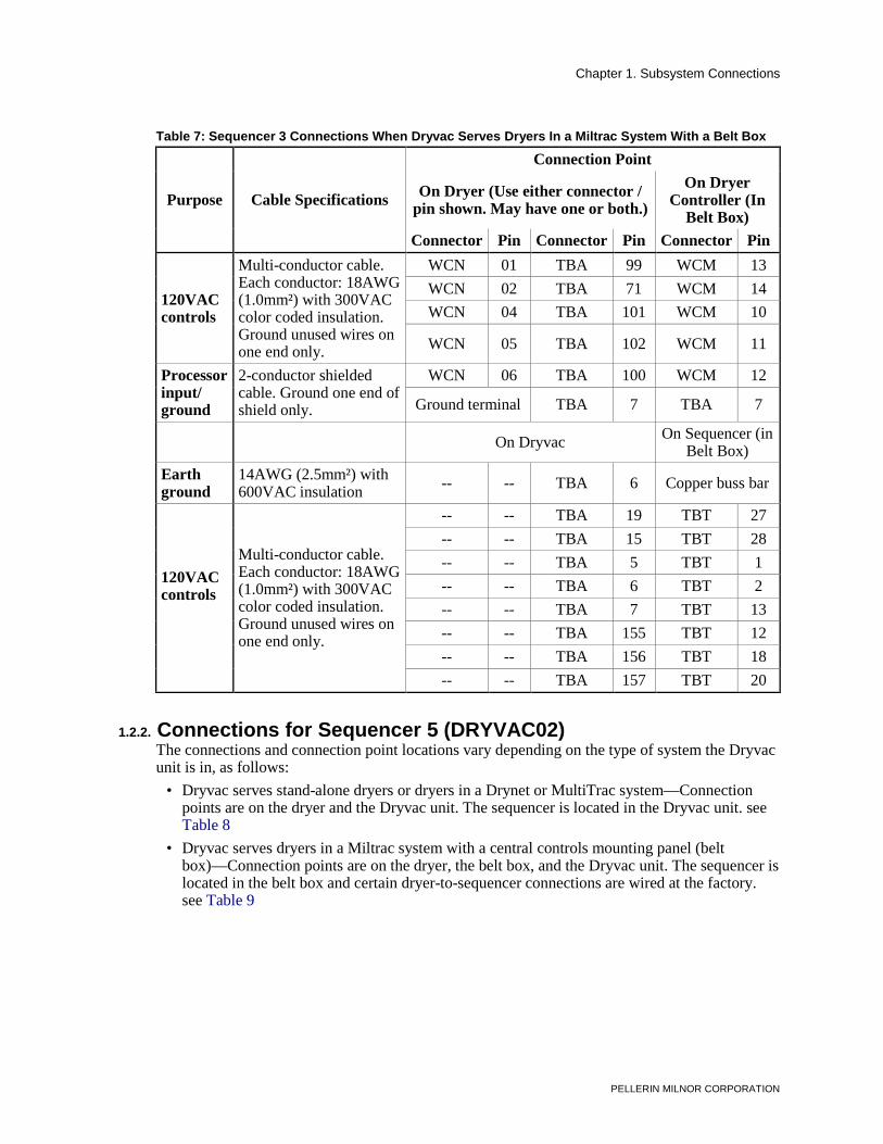
• Dryvac serves dryers in a Miltrac system with a central controls mounting panel (belt box)—Connection points are on the dryer, the belt box, and the Dryvac unit. The sequencer is located in the belt box and certain dryer-to-sequencer connections are wired at the factory. see Table 7
Table 6: Sequencer 3 Connections When Dryvac Serves Stand-alone Dryers or Dryers in a Drynet or MultiTrac System
Purpose Cable
Specifications
Connection Point On Dryer (Use either connector / pin
shown. May have one or both.) On Sequencer (on Dryvac)
Dryer # Connector Pin Connector Pin Connector Pin
Earth ground
14AWG (2.5mm²) with 600VAC insulation
-- -- -- TBA 6 Copper buss bar
Multi-conductor cable. Each conductor: 18AWG (1.0mm²) with 300VAC color coded insulation. Ground unused wires one end only.
1.2.2. Connections for Sequencer 5 (DRYVAC02) The connections and connection point locations vary depending on the type of system the Dryvac unit is in, as follows:
• Dryvac serves stand-alone dryers or dryers in a Drynet or MultiTrac system—Connection points are on the dryer and the Dryvac unit. The sequencer is located in the Dryvac unit. see Table 8
• Dryvac serves dryers in a Miltrac system with a central controls mounting panel (belt box)—Connection points are on the dryer, the belt box, and the Dryvac unit. The sequencer is located in the belt box and certain dryer-to-sequencer connections are wired at the factory. see Table 9
Chapter 1. Subsystem Connections
PELLERIN MILNOR CORPORATION
Table 8: Sequencer 5 Connections When Dryvac Serves Stand-alone Dryers or Dryers In a Drynet or MultiTrac System
Purpose Cable
Specifications
Connection Point On Dryer (Use either connector / pin
shown. May have one or both.) On Sequencer (on Dryvac)
Dryer # Connector Pin Connector Pin Connector Pin
Earth ground
14AWG (2.5mm²) with 600VAC insulation
-- -- -- TBA 6 Copper buss bar
Multi-conductor cable. Each conductor: 18AWG (1.0mm²) with 300VAC color coded insulation. Ground unused wires on one end only.
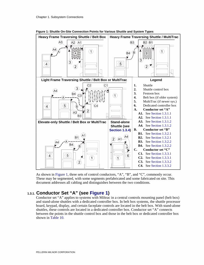
1.3. On-Site Control Connections for Shuttles With Mark 5 Controls This document covers typical connection procedures for shuttles used in Miltrac and MultiTrac systems. Special conditions not shown here may also arise. Contact Milnor Technical Support for assistance with conditions not shown. Referring to Figure 1, the types of on-site connections vary with the combination of:
• shuttle type: 1) heavy frame, traversing, 2) light frame, traversing, or 3) elevate-only, and • system control type: 1) Miltrac in a central controls mounting panel (belt box), 2) MultiTrac,
or 3) shuttle stand-alone.
Chapter 1. Subsystem Connections
PELLERIN MILNOR CORPORATION
Figure 1: Shuttle On-Site Connection Points for Various Shuttle and System Types
Heavy Frame Traversing Shuttle / Belt Box Heavy Frame Traversing Shuttle / MultiTrac
Light Frame Traversing Shuttle / Belt Box or MultiTrac Legend
1. Shuttle 2. Shuttle control box 3. Festoon box 4. Belt box (if older system) 5. MultiTrac (if newer sys.) 6. Dedicated controller box A. Conductor set “A” A1. See Section 1.3.1.1 A2. See Section 1.3.1.1 A3. See Section 1.3.1.2 A4. See Section 1.3.1.2 B. Conductor set “B” B1. See Section 1.3.2.1 B2. See Section 1.3.2.1 B3. See Section 1.3.2.2 B4. See Section 1.3.2.2 C. Conductor set “C” C1. See Section 1.3.3.1 C2. See Section 1.3.3.1 C3. See Section 1.3.3.2 C4. See Section 1.3.3.2
Elevate-only Shuttle / Belt Box or MultiTrac Stand-alone Shuttle (see
Section 1.3.4)
. As shown in Figure 1, three sets of control conductors, “A”, “B”, and “C”, commonly occur. These may be segmented, with some segments prefabricated and some fabricated on site. This document addresses all cabling and distinguishes between the two conditions.
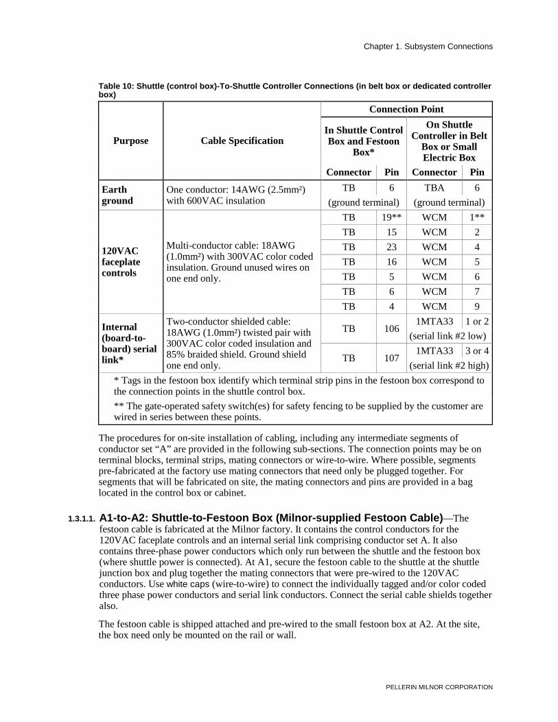
1.3.1. Conductor Set “A” (see Figure 1) Conductor set “A” applies to systems with Miltrac in a central controls mounting panel (belt box) and stand-alone shuttles with a dedicated controller box. In belt box systems, the shuttle processor board, keypad, display, and certain faceplate controls are located in the belt box. With stand-alone shuttles, these controls are located in a dedicated controller box. Conductor set “A” connects between the points in the shuttle control box and those in the belt box or dedicated controller box shown in Table 10.
Chapter 1. Subsystem Connections
PELLERIN MILNOR CORPORATION
Table 10: Shuttle (control box)-To-Shuttle Controller Connections (in belt box or dedicated controller box)
Purpose Cable Specification
Connection Point
In Shuttle Control Box and Festoon
Box*
On Shuttle Controller in Belt
Box or Small Electric Box
Connector Pin Connector Pin Earth ground
One conductor: 14AWG (2.5mm²) with 600VAC insulation
TB 6 TBA 6 (ground terminal) (ground terminal)
120VAC faceplate controls
Multi-conductor cable: 18AWG (1.0mm²) with 300VAC color coded insulation. Ground unused wires on one end only.
Two-conductor shielded cable: 18AWG (1.0mm²) twisted pair with 300VAC color coded insulation and 85% braided shield. Ground shield one end only.
TB 106 1MTA33 1 or 2
(serial link #2 low)
TB 107 1MTA33 3 or 4
(serial link #2 high) * Tags in the festoon box identify which terminal strip pins in the festoon box correspond to
the connection points in the shuttle control box. ** The gate-operated safety switch(es) for safety fencing to be supplied by the customer are
wired in series between these points. The procedures for on-site installation of cabling, including any intermediate segments of conductor set “A” are provided in the following sub-sections. The connection points may be on terminal blocks, terminal strips, mating connectors or wire-to-wire. Where possible, segments pre-fabricated at the factory use mating connectors that need only be plugged together. For segments that will be fabricated on site, the mating connectors and pins are provided in a bag located in the control box or cabinet.
1.3.1.1. A1-to-A2: Shuttle-to-Festoon Box (Milnor-supplied Festoon Cable)—The festoon cable is fabricated at the Milnor factory. It contains the control conductors for the 120VAC faceplate controls and an internal serial link comprising conductor set A. It also contains three-phase power conductors which only run between the shuttle and the festoon box (where shuttle power is connected). At A1, secure the festoon cable to the shuttle at the shuttle junction box and plug together the mating connectors that were pre-wired to the 120VAC conductors. Use white caps (wire-to-wire) to connect the individually tagged and/or color coded three phase power conductors and serial link conductors. Connect the serial cable shields together also. The festoon cable is shipped attached and pre-wired to the small festoon box at A2. At the site, the box need only be mounted on the rail or wall.
Chapter 1. Subsystem Connections
PELLERIN MILNOR CORPORATION
1.3.1.2. A3-to-A4: Festoon Box-to-Belt Box (fabricated on site)—Whether the connections at A3 are made in the festoon box, as with heavy frame shuttles or in the shuttle control box, as with light frame shuttles, the connections are the same. Tags in the festoon box identify which terminal strip pins in the festoon box correspond to the shuttle control box connection points. Refer to Table 10 in either case.
1.3.2. Conductor Set “B” (see Figure 1) Conductor set “B” applies to MultiTrac systems. In such systems, the shuttle processor board is located in the shuttle control box and communicates with MultiTrac via two or more serial links. Also, certain Shuttle faceplate controls are located on the MultiTrac cabinet. Conductor set “B” connects between the points in the shuttle control box and those in the MultiTrac cabinet shown in Table 11.
* Asterisk represents the shuttle number, as displayed in the faceplate controls. ** Tags in the festoon box identify which terminal strip pins in the festoon box correspond
to the connection points in the shuttle control box. *** The gate-operated safety switch(es) for safety fencing to be supplied by the customer are
wired in series either between pins TB18 (shown) and TB19 in the shuttle box, or between pins TBC19 (shown) and TBC18 in the Multitrac cabinet.
The procedures for on-site installation of cabling, including any intermediate segments of conductor set “B” are provided in the following sub-sections. The connection points may be on terminal blocks, mating connectors, or wire-to-wire. Where possible, segments pre-fabricated at the factory use mating connectors that need only be plugged together. For segments that will be
Chapter 1. Subsystem Connections
PELLERIN MILNOR CORPORATION
wired on site, the mating connectors and pins are provided in a bag located in the control box or cabinet.
1.3.2.1. B1-to-B2: Shuttle-to-Festoon Box (Milnor-supplied Festoon Cable)—The festoon cable is fabricated at the Milnor factory. It contains the control conductors for the 120VAC faceplate controls and the external serial links (Miltrac, Mildata, and optional Drynet) comprising conductor set B. It also contains three-phase power conductors which only run between the shuttle and the festoon box (where shuttle power is connected). At B1, secure the festoon cable to the shuttle at the shuttle junction box and plug together the mating connectors that were pre-wired to the 120VAC conductors. Use white caps (wire-to-wire) to connect the individually tagged and/or color coded three phase power conductors and serial link conductors. Connect the serial cable shields together also. The festoon cable is shipped attached and pre-wired to the small festoon box at B2. At the site, the box need only be mounted to the rail or wall.
1.3.2.2. B3-to-B4: Festoon Box-to-MultiTrac (Customer-supplied Cabling)—Whether the connections at B3 are made in the festoon box, as with heavy frame shuttles, or in the shuttle control box, as with light frame shuttles, the connections are the same. Tags in the festoon box identify which terminal block pins in the festoon box correspond to the shuttle control box connection points. Refer to Table 11 in either case.
1.3.3. Conductor Set “C” (see Figure 1) Conductor set “C” applies to systems with light frame traversing shuttles. In such systems, the shuttle control box, which is otherwise mounted on the shuttle frame is a free-standing cabinet located near the end of the shuttle path. This conductor set is comprised of 120VAC conductors for faceplate controls and individual motor feeds. Conductor set “C” connects between the shuttle and the remote shuttle control box. All connector set “C” segments are pre-fabricated at the factory. The procedures for on-site installation of the conductor set “C” segments are provided in the following sub-sections. The connection points may be on terminal blocks, terminal strips, or pre-wired mating connectors.
1.3.3.1. C1-to-C2: Shuttle-to-Festoon Box (Milnor-supplied Festoon Cable)—The festoon cable is fabricated at the Milnor factory. At C1, secure the festoon cable to the shuttle at the shuttle junction box and plug together the mating connectors for the 120VAC conductors. Wire the motor feeds to the terminal block, matching the tags on the wires to those on the terminal block. The festoon cable is shipped attached and pre-wired to the small festoon junction box at C2. At the site, the box need only be mounted on the rail or wall.
1.3.3.2. C3-to-C4: Festoon Box-to-Shuttle Control Box (Milnor-supplied Cable)—All control conductors are in flexible cabling supplied by Milnor. The shuttle control box ships with the cable attached and pre-wired on this end (C4). At C3, secure the cable to the festoon box and plug together the pre-wired mating connectors for the 120VAC conductors. Wire the motor feed conductors the the terminal block, matching the tags on the individual conductors to those on the terminal block. A connector and pin identification tag is also provided in the festoon box.
1.3.4. About the Controls for Stand-alone, Elevating Shuttles Elevate-only, stand-alone shuttles have a dedicated controller box containing the shuttle processor board, keypad, display and certain faceplate controls (see Note 3). The cabling between the
Chapter 1. Subsystem Connections
PELLERIN MILNOR CORPORATION
shuttle and this box is conductor set “A” (see Table 10). However, the on-site connections, if any, are usually made with mating connectors.
This type of shuttle is most often used to load a Milnor dryer in a stand-alone (not part of an automated laundering system) configuration, and as such, is dedicated to that dryer. Typically, the shuttle and dryer controls are located together. These are usually, but not necessarily, mounted on the shuttle frame.
Note 3: Previously, Milnor stand-alone, elevate-only shuttles used relay logic controls. Today, these shuttles are only offered with microprocessor controls.
1.3.4.1. Stand-alone Shuttle Controls Mounted on the Shuttle Frame—If the dedicated controller box is mounted on the shuttle frame, no on site connections for the shuttle are required. However, if the dryer control box is also mounted to the shuttle frame, on-site connections are required for the dryer. These are made via a flexible conduit. The shuttle will normally ship with the dryer control box mounted and the cabling attached. All connections on the shuttle end pre-wired, and mating connectors pre-wired on the other end. At the site, secure the other end of the cabling to the dryer and mate the connectors. Refer to Section 1.1. “On-Site Control Connections for Dryers With Mark 5 Controls” for more information.
1.3.4.2. Stand-alone Shuttle Controls Located Remotely—If the dedicated controller box will be near, but not on the shuttle frame (for example, if it is mounted on the dryer), the connections are normally made via a flexible conduit supplied by Milnor. The shuttle will normally ship with the cabling attached, all connections on the shuttle end pre-wired, and mating connectors installed on the other end. At the site, secure the other end of the conduit to the dedicated controller box, and mate the connectors.
1.4. On-Site Control Connections for Device Master, PC Device Master, Linear Costa, and Linear Costa Master This document applies to the following controllers when used to control Milnor flat bed conveyors:
• Device Master and PC Device Master—Both of these controllers permit up to four, or up to eight devices (depending on the capacity specified) to be independently controlled and used for any of several specialized purposes (see Note 4). Device Master works with the older Miltrac system in a central controls mounting panel (belt box). PC Device Master works with newer MultiTrac systems.
• Liner Costa Controller—permits a single conveyor to be used as a multi-cake storage device (see Note 5).
• Linear Costa Master Controller—permits up to four, or up to eight conveyors (depending on the capacity specified) to be independently controlled and used as multi-cake storage devices (see Note 5).
Note 4: Device Master and PC Device Master provide for seven device types (seven specialized functions). Five apply to conveyors. One—the “non-storage belt” type—can apply to either a conveyor or a phantom belt. In the latter case, no physical connections are required because there is no physical device. The remaining function, called “allied dryer”, provides for using allied dryers in a Miltrac or MultiTrac system with greater functionality than a machine-to-machine allied interface would provide. This device type only involves allied interface connections.
Note 5: As of this writing, Linear Costa and Linear Costa Master products specifically for use in MultiTrac systems have not been implemented.
Chapter 1. Subsystem Connections
PELLERIN MILNOR CORPORATION
These controllers perform two types of functions that require on-site wiring: 1. Each serves as a machine controller for conveyor belts. In this respect, these controllers are
comparable to the microprocessor controller on any machine (except that a single Device Master or Linear Costa Master can act as several controllers—one for each belt they control). But because these controllers are located in a central control cabinet shipped and installed separately from the conveyor(s), the machine functions must be “wired in” on site, as described herein.
2. Because the conveyor(s) can receive from, and discharge to allied (non-Milnor) devices, each controller can communicate with the allied equipment via allied interfaces. Allied interface connections are made on site. Refer to manual MTPALI01 “Allied Interfaces for Milnor Automated Laundering System Machines...” for more information.
Although these controllers communicate with Miltrac, the serial links are normally wired at the factory because all components are housed in the same cabinet. However, the connection procedures are described in document BICCUC01, “On-Site Installation and Troubleshooting of Permanent Serial Communication Cables.”
Regardless of the specific purpose a conveyor belt serves, all flat bed conveyors controlled by any of these controllers perform the same basic machine functions: running the belt and detecting, via photo eyes, the presence of goods. Depending on specific purpose and options, a conveyor may also perform specialized functions such as extending and retracting or signaling personnel via load lights.
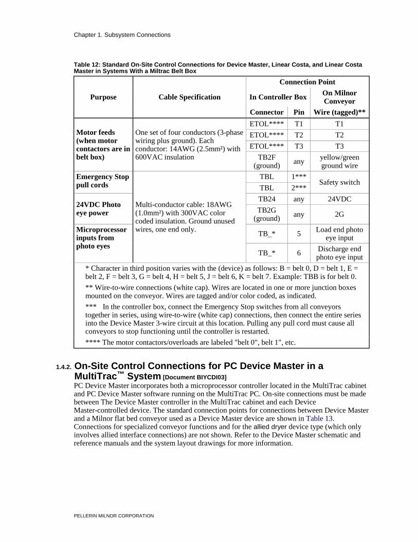
1.4.1. On-Site Control Connections for Device Master, Linear Costa, or Linear Costa Master in a Miltrac™ System [Document BIYCDI02] In a Miltrac system with the Miltrac controller mounted in a central controls mounting panel (belt box), these controllers are also mounted in the belt box. On-site connections must be made between the controller box in the belt box and each conveyor. The standard controller-to-conveyor connections, which are the same for all three controllers, are shown in Table 12. Connections for specialized conveyor functions and for allied interfaces are not shown. Refer to the controller schematic and reference manuals, and the system layout drawings for more information.
Chapter 1. Subsystem Connections
PELLERIN MILNOR CORPORATION
Table 12: Standard On-Site Control Connections for Device Master, Linear Costa, and Linear Costa Master in Systems With a Miltrac Belt Box
Purpose Cable Specification
Connection Point In Controller Box
On Milnor Conveyor
Connector Pin Wire (tagged)**
Motor feeds (when motor contactors are in belt box)
One set of four conductors (3-phase wiring plus ground). Each conductor: 14AWG (2.5mm²) with 600VAC insulation
ETOL**** T1 T1 ETOL**** T2 T2 ETOL**** T3 T3
TB2F (ground)
any yellow/green ground wire
Emergency Stop pull cords
Multi-conductor cable: 18AWG (1.0mm²) with 300VAC color coded insulation. Ground unused wires, one end only.
TBL 1*** Safety switch TBL 2***
24VDC Photo eye power
TB24 any 24VDC TB2G
(ground) any 2G
Microprocessor inputs from photo eyes
TB_* 5 Load end photo
eye input TB_* 6
Discharge end photo eye input
* Character in third position varies with the (device) as follows: B = belt 0, D = belt 1, E = belt 2, F = belt 3, G = belt 4, H = belt 5, J = belt 6, K = belt 7. Example: TBB is for belt 0.
** Wire-to-wire connections (white cap). Wires are located in one or more junction boxes mounted on the conveyor. Wires are tagged and/or color coded, as indicated.
*** In the controller box, connect the Emergency Stop switches from all conveyors together in series, using wire-to-wire (white cap) connections, then connect the entire series into the Device Master 3-wire circuit at this location. Pulling any pull cord must cause all conveyors to stop functioning until the controller is restarted.
**** The motor contactors/overloads are labeled "belt 0", belt 1", etc.
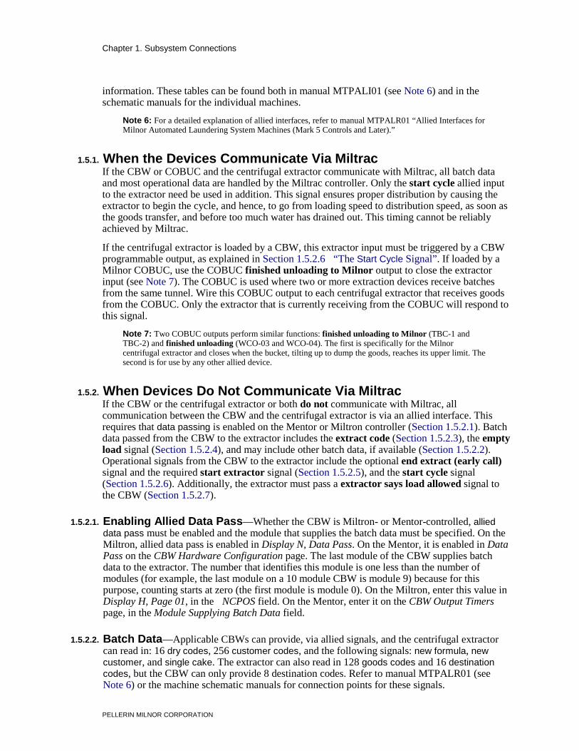
1.4.2. On-Site Control Connections for PC Device Master in a MultiTrac™ System [Document BIYCDI03] PC Device Master incorporates both a microprocessor controller located in the MultiTrac cabinet and PC Device Master software running on the MultiTrac PC. On-site connections must be made between The Device Master controller in the MultiTrac cabinet and each Device Master-controlled device. The standard connection points for connections between Device Master and a Milnor flat bed conveyor used as a Device Master device are shown in Table 13. Connections for specialized conveyor functions and for the allied dryer device type (which only involves allied interface connections) are not shown. Refer to the Device Master schematic and reference manuals and the system layout drawings for more information.
Chapter 1. Subsystem Connections
PELLERIN MILNOR CORPORATION
Table 13: Device Master On-Site Control Connections in MultiTrac Systems
Purpose Cable Specification
Connection Point On Device Master
Controller Contactor Box On
Conveyor Connector Pin Connector Pin
Emergency Stop pull cords
TBL 1** TBC 1 TBL 2** TBC 2
24VDC Photo eye power
TB24 any TBC 7
Multi-conductor cable: 18AWG (1.0mm²) with 300VAC color coded insulation. Ground unused wires, one end only.
TB2G (ground)
any TBC 6 Microprocessor inputs from photo eyes
TB_* 5 TBC 8 TB_* 6 not implemented
Microprocessor outputs to reversing contactors
TB_* 3 TBC 5 TB_* 4 TBC 6
Earth ground TB2F
(ground) any TBC 4
* Character in third position varies with the (device) as follows: B = belt 0, D = belt 1, E = belt 2, F = belt 3, G = belt 4, H = belt 5, J = belt 6, K = belt 7. Example: TBB is for belt 0.
** In the Device Master control box, connect the Emergency Stop switches from all conveyors together in series, using wire-to-wire (white cap) connections, then connect the entire series into the Device Master 3-wire circuit at this location. Pulling any pull cord must cause all conveyors to stop functioning until Device Master is restarted.
1.5. Special Load Interface Requirements for the Milnor® Centrifugal Extractor Regardless of what device loads a Milnor centrifugal extractor or what type of system the extractor is in, communication between the extractor and the loading device requires one or more allied interface connections (see Note 6). This document explains how to establish these connections when:
• the centrifugal extractor is loaded by a Milnor CBW® or Milnor COBUC (wet goods shuttle) and both devices communicate with Miltrac™ (either the older Miltrac controller or PC Miltrac software running on a MultiTrac PC),
• the centrifugal extractor is loaded by a Milnor CBW controlled by a Mentor® or Mark 8 Miltron™ controller, but one or both of the devices do not communicate with Miltrac.
Unlikely and/or nonspecific loading devices (e.g., COBUC in a non-Miltrac system, CBW with non-serial controls, allied tunnel) are not covered in this document. For such conditions, consult with Milnor Technical Support.
Allied interface signals are referred to in this document by their common names only. Connection points (terminal and pin number) are not provided. See the allied interface signals tables for this
Chapter 1. Subsystem Connections
PELLERIN MILNOR CORPORATION
information. These tables can be found both in manual MTPALI01 (see Note 6) and in the schematic manuals for the individual machines.
Note 6: For a detailed explanation of allied interfaces, refer to manual MTPALR01 “Allied Interfaces for Milnor Automated Laundering System Machines (Mark 5 Controls and Later).”
1.5.1. When the Devices Communicate Via Miltrac If the CBW or COBUC and the centrifugal extractor communicate with Miltrac, all batch data and most operational data are handled by the Miltrac controller. Only the start cycle allied input to the extractor need be used in addition. This signal ensures proper distribution by causing the extractor to begin the cycle, and hence, to go from loading speed to distribution speed, as soon as the goods transfer, and before too much water has drained out. This timing cannot be reliably achieved by Miltrac.
If the centrifugal extractor is loaded by a CBW, this extractor input must be triggered by a CBW programmable output, as explained in Section 1.5.2.6 “The Start Cycle Signal”. If loaded by a Milnor COBUC, use the COBUC finished unloading to Milnor output to close the extractor input (see Note 7). The COBUC is used where two or more extraction devices receive batches from the same tunnel. Wire this COBUC output to each centrifugal extractor that receives goods from the COBUC. Only the extractor that is currently receiving from the COBUC will respond to this signal.
Note 7: Two COBUC outputs perform similar functions: finished unloading to Milnor (TBC-1 and TBC-2) and finished unloading (WCO-03 and WCO-04). The first is specifically for the Milnor centrifugal extractor and closes when the bucket, tilting up to dump the goods, reaches its upper limit. The second is for use by any other allied device.
1.5.2. When Devices Do Not Communicate Via Miltrac If the CBW or the centrifugal extractor or both do not communicate with Miltrac, all communication between the CBW and the centrifugal extractor is via an allied interface. This requires that data passing is enabled on the Mentor or Miltron controller (Section 1.5.2.1). Batch data passed from the CBW to the extractor includes the extract code (Section 1.5.2.3), the empty load signal (Section 1.5.2.4), and may include other batch data, if available (Section 1.5.2.2). Operational signals from the CBW to the extractor include the optional end extract (early call) signal and the required start extractor signal (Section 1.5.2.5), and the start cycle signal (Section 1.5.2.6). Additionally, the extractor must pass a extractor says load allowed signal to the CBW (Section 1.5.2.7).
1.5.2.1. Enabling Allied Data Pass—Whether the CBW is Miltron- or Mentor-controlled, allied data pass must be enabled and the module that supplies the batch data must be specified. On the Miltron, allied data pass is enabled in Display N, Data Pass. On the Mentor, it is enabled in Data Pass on the CBW Hardware Configuration page. The last module of the CBW supplies batch data to the extractor. The number that identifies this module is one less than the number of modules (for example, the last module on a 10 module CBW is module 9) because for this purpose, counting starts at zero (the first module is module 0). On the Miltron, enter this value in Display H, Page 01, in the NCPOS field. On the Mentor, enter it on the CBW Output Timers page, in the Module Supplying Batch Data field.
1.5.2.2. Batch Data—Applicable CBWs can provide, via allied signals, and the centrifugal extractor can read in: 16 dry codes, 256 customer codes, and the following signals: new formula, new customer, and single cake. The extractor can also read in 128 goods codes and 16 destination codes, but the CBW can only provide 8 destination codes. Refer to manual MTPALR01 (see Note 6) or the machine schematic manuals for connection points for these signals.
Chapter 1. Subsystem Connections
PELLERIN MILNOR CORPORATION
The extractor can be programmed for 16 discrete extract codes. Some, but not all applicable CBWs provide these. However, a work-around is available to handle extract codes, as explained in Section 1.5.2.3, below. The extractor can also read in an empty load signal. This must be handled as explained in Section 1.5.2.4, below.
1.5.2.3. Using Drycode for Extract Code on Certain CBW's—Some CBWs explicitly provide 16 extract code output signals. The following CBW controllers do not:
• Miltron controller with a software version 9401C or earlier • Mentor controller with Generation2 (G2) Mentor software version 97107 or earlier • Mentor controller with any Generation3 (G3) Mentor software version
On CBW's with any of the controllers listed above, the four output signals for drycode must be used instead for the extract code. If the CBW is Miltron-controlled, the extract codes would be programmed in the Drycodes column of Miltron Display H, page 3, field B. If the CBW is Mentor-controlled, they would be entered, instead of drycode, in the Post Wash Codes zone of the Formula Programming page. Of course, this means that another method must be used to introduce dry codes farther downstream in the system, if needed.
1.5.2.4. The Empty Load Signal—The CBW does not provide an explicit “empty load” (also referred to as pass empty) allied output. However, the “don't main press goods” output, normally used with the Milnor two-stage press, may be used for this purpose. Wire this output to the empty load input on the extractor. Whether the CBW is Miltron or Mentor controlled, enable this output for the “pass empty” formula by programming a value of 1 for press pressure. On the Mark 8 Miltron, this is Display H, Page 3, Field E. On the Mentor, this is the Pressure drop down box (not the Pass Empty check box) in the Post-Wash Codes zone of the Formula Programming page.
1.5.2.5. The End Extract (Early Call) and Start Extractor Signals—The end extract (early call) (if used) and start extractor inputs on the extractor can both be enabled at the same time. Hence, they can be served by a single output on the CBW. There is no explicit allied output provided for this purpose. Rather, a programmable output (C-bit) assigned to the last module must be allocated and wired to both the early call / end extract and loading mode / start extractor inputs on the extractor. This output is programmed as follows (whether the CBW is Miltron or Mentor controlled):
Compatibility = off Op code = 09 (“Early Call”) Hold code = N (or not checked) Init code = A On time = 255 (for every formula)
1.5.2.6. The Start Cycle Signal—Although the CBW does provide an explicit start press allied output, this is only for use with the press, not the extractor. Rather, for proper timing, a programmable output assigned to the last module must be allocated and wired to the to the extractor start cycle input. Whether a Miltron or a Mentor, this output is programmed as follows:
Compatibility = off Hold code = N (or not checked) Op code = 00 (“Standard Timed”) Init code = H On time = 004 (for every formula)
Chapter 1. Subsystem Connections
PELLERIN MILNOR CORPORATION
1.5.2.7. The Extractor Says Load Allowed Signal—The extractor says load allowed output on the extractor signals the CBW that it is free to receive a load. On a CBW with a Miltron controller or a Generation2 (G2) Mentor controller, connect this output to the explicitly provided press free allied input. The Generation3 (G3) Mentor controller does not provide an explicit press free input. On these machines, allocate a programmable input for this purpose and assign it input op code 11 (“Press Free”).
2.1. How Milnor® System Machines and Fully Programmable Washer-Extractors Use Serial Communication Serial communication refers to the transfer of data sequentially (one bit at a time rather than several bits simultaneously, as in parallel communication). Two common serial communication protocols are: RS485—This is a multi-drop protocol; that is, several devices can be connected to the same serial
communication line. RS485 can function reliably over distances of up to 4000 feet (roughly 1200 meters) and is well suited to many Milnor applications. The RS485 architecture used by Milnor employs a serial high line and a serial low line which carry data bi-directionally.
RS232—This protocol is only intended to connect two devices (point-to-point) over distances of up to 50 feet (15 meters). Milnor uses RS232 to communicate with printers (a common use), employing only the transmit data (TXD), clear to send (CTS), and ground lines.
The internal communication between the processor and the peripheral boards on Milnor system machines and fully programmable washer-extractors in current production is handled serially (see Note 8). These machines can also communicate with various external devices serially, via additional serial ports on the processor board. Depending on machine type, these external devices may include:
• Miltrac™ controller (or a MultiTrac™ PC running PC Miltrac software) • Mildata® PC (or a MultiTrac PC running the Mildata data collection engine) • Drynet dryer/shuttle controller (or a MultiTrac PC running Drynet software) • certain makes and models of PC printers (for printing reports) • certain makes and models of ticket printers (for automatically printing batch data tickets) • Milnor download device (for transferring programmable data such as wash formulas) • a compatible Milnor machine (for transferring programmable data such as wash formulas)
Note 8: Older Milnor microprocessor controllers—those that use a motherboard design—are referred to as non-serial because the processor communicates with the peripheral boards (e.g., IO boards) via a parallel communication bus on the motherboard. The controllers for applicable machines in current production are referred to as serial because the processor communicates with the peripheral boards via a serial port. The non-serial and some older serial boards used the Intel® 8085 microprocessor. Processor boards in current production use the Intel® 8088 and 80186 microprocessors.
Processor boards with the 8088 chip, and and those with the 80186 chip provide four and six serial ports respectively. All serial ports except for the printer port use RS485 protocol. The printer port uses RS232. Typically, the ports used for report printing and downloading
Chapter 2. System Connections (Serial Links)
PELLERIN MILNOR CORPORATION
(machine-to-machine or machine-to-download device) are wired to a DIN receptacle accessible from outside the electric box, so that the customer can make either a temporary, or a permanent connection as appropriate. See Milnor document BICWUC01 “Construction of External Serial Link Cables” for more information. The serial cables that link the machine to any of the other devices mentioned, are permanent connections that must be fabricated and installed on site in accordance with Milnor document BICCUC01 “On Site Installation and Troubleshooting of Permanent Serial Communication Cables.”
2.2. On-Site Installation and Troubleshooting of Permanent Serial Communication Cables Permanent serial communication cables are those that must be connected directly to microprocessor boards via MTA connectors on the board, not those installed via cabinet-mounted DIN receptacles provided for customer use (see BICWUC01 “Construction of External Serial Link Cables”). Permanent serial cables should be installed only by trained technicians.
Miltrac™, Drynet (dryer/shuttle controller) and Mildata®, whether provided separately or included with MultiTrac™, each requires its own serial communication wiring to link the controller with its subordinate machines. Portions of this wiring must be fabricated and installed on site. The portions that do not need to be field installed are those where several components to be connected are located on equipment shipped as a single unit. For example, in systems where the processor boards for all dryers and shuttles are located in a central controls mounting panel (belt box), the corresponding Miltrac data lines on each board are wired together at the Milnor factory. The field wiring need only connect to one of these boards.
All devices connected to a central controller share the same serial port on that controller. Cable routing has no bearing on the ability of the central controller to distinguish devices (this is handled by identification codes preset on each device and configured in the controller software). Hence, the devices can be connected to the controller either via direct controller-to-machine (“home run”) wiring or via “daisy chaining”.
2.2.1. “Daisy Chain” Versus “Home Run” Wiring daisy chain (recommended)—a method of linking several devices (machines) to a central
controller by running a single, segmented cable from device to device, throughout the entire bank of devices. Each serial port on a Milnor processor board has two internally-connected pins dedicated to each data line. Serial low is pins 1 and 2 and serial high is pins 3 and 4. In most cases, all four pins, as well as two unused pins (5 and 6) comprise a single, six-pin MTA connector (see Figure 2 in Section 2.2.3.1). By convention, the incoming daisy chain segment is brought in on pins 1 and 3 and the next daisy chain segment begins on pins 2 and 4.
home run (discouraged)—a method of linking several devices (machines) to a central controller by running a separate serial cable from the controller to each device. With this method, all serial high lines are spliced together on the controller end, as are all serial low lines.
2.2.2. Specifications and Requirements Because the interconnected devices may be at different ground potentials and because the field-installed cabling is particularly susceptible to electrical noise, specific cabling material and grounding procedures must be adhered to.
Chapter 2. System Connections (Serial Links)
PELLERIN MILNOR CORPORATION
2.2.2.1. Cable Specifications—Most new CBW systems include MultiTrac®. MultiTrac always includes PC Miltrac (the Miltrac controller) and Online Communicator software (the Mildata data collection function). In most cases, optional Drynet (the Dryer/Shuttle controller) is also provided. Each of these controllers requires a separate serial link to communicate with its subordinate machines. Miltrac and Online Communicator typically communicate with every Milnor machine in the system. Drynet communicates with every Milnor dryer and shuttle. Hence, it is convenient to run a six-conductor serial communication cable (three serial links) between the MultiTrac console and each dryer and shuttle, and a four- or six-conductor cable between MultiTrac and every other Milnor machine. Cables serving this purpose must conform to the following specification:
• Two twisted pair (four-conductors) or three twisted pair (six-conductors), as follows: » Conductive material: Tinned copper, 18 AWG (1.0mm²) » Insulation: 300VAC, color coded » Positive wire identification by color coding and/or wire number.
Cables meeting the above specification are available from Milnor, as follows: Four-conductor—P/N 09V300B04S Six-conductor—P/N 09V300B06S
2.2.2.2. Conduit Requirements—Consult local codes to determine any requirement to run serial communication cables within conduit. In the absence of such a requirement, consider cable protection, and in any case observe the following precaution:
CAUTION 1 : Risk of Bad Data—Inadequate shielding against electrical noise can trigger false signals. • Do not run serial cables adjacent to, or in the same conduit with wires that provide motor
power or similar. It is permissible to run serial cables in the same conduit with Milnor control circuit conductors (DC and/or AC), and with control circuit ground (earth) conductors used to ground the various controllers together.
• If serial cables are run in a cable tray, insure the tray does not also contain wires for motor power or similar and that such conductors are not subsequently added.
2.2.2.3. Grounding the Controllers—Connect the high voltage control circuit ground terminals (normally pin 2F) together in all controllers to be linked via a serial cable or via any other control conductors. Use 14AWG (2.5mm²) conductors with 600VAC insulation.
CAUTION 2 : Risk of component damage and warranty loss—Powering up machines before controller-to-controller grounds are properly established will burn out microprocessor boards and void the warranties. • Install secure grounds as described above before first applying power.
2.2.2.4. Grounding the Shield and Unused Wires—Ground the serial cable shield and unused wires as follows, to obtain the best protection against electrical noise and to counteract any tendancy of the spare wires to act as antennas.
2.2.2.4.1. If the “Home Run” Method Is Used—Splice together the shields and any spare wires for all cables where they converge inside the MultiTrac console or central controls mounting panel (belt
Chapter 2. System Connections (Serial Links)
PELLERIN MILNOR CORPORATION
box). Connect the spliced shields and wires to signal ground (normally pin 2G or pin 7) within the cabinet. On the opposite end of each cable, leave the shields unconnected and individually cap or tape each spare wire.
2.2.2.4.2. If the “Daisy Chain” Method Is Used 1. Connect together the abutting ends of the shield at each location where the daisy chain
segments meet (at each intermediate device), but do not connect them to anything else. The objective is to achieve continuity in the shield across the entire length of the daisy chain. If a segment enclosed in an electric box (a factory installed segment) falls in the middle of the daisy chain, install a wire inside the electric box to connect the incoming shield to the outgoing shield. Do not ground the shield inside this box.
2. Do the same as above for each spare wire. 3. On the end of the daisy chain that connects to the system controller, connect the shield and
spare wires to signal ground (normally pin 2G or pin 7) within the controller's electric box. 4. On the opposite end of the daisy chain, leave the shield unconnected and individually cap or
tape each spare wire.
2.2.3. Connecting the Serial Link To Subordinate Devices (Machines)
WARNING 3 : Electrocution and Electrical Burn Hazards—Contact with electric power can kill or seriously injure you. Electric power is present inside the cabinetry unless the main machine power disconnect is off. • Do not service the machine unless qualified and authorized. You must clearly understand
the hazards and how to avoid them.
2.2.3.1. Identifying Serial Ports—As shown in Figure 2, labels imprinted on the processor board (e.g., “1MTA32 RS485 #1”) identify the serial ports. By convention, Milnor dedicates the same serial ports on different devices to certain functions (see Table 14). For example, the software for every Milnor machine that can function as a Miltrac device (press, centrifugal extractor, shuttle, dryer, etc.) is written to communicate with Miltrac via the serial port at MTA32. However, do not rely solely on the convention shown in Table 14. Always consult the system connection instructions in the device or system controller schematic manual to confirm serial link connection points.
Chapter 2. System Connections (Serial Links)
PELLERIN MILNOR CORPORATION
Table 14: Serial Port Dedicated Uses
Serial Port Identification Serial Port Function 8088 Board
Serial Link #
80186 Board Serial Link #
n/a -- MTA29 4
Textile machines: Chemflow boards CBWs: peripheral boards (second port)*** Dryers, shuttles: Drynet (dryer/shuttle controller) All others: not used
MTA30* (RS232) or**
MTA30* (RS485)
4
MTA30* (RS232)
-- Printer**** MTA30* (RS485)
-- Serial display (on devices so equipped) MTA32 1 MTA32 1 Miltrac MTA33 2 MTA33 2 Peripheral boards MTA34 3 MTA34 3 Mildata / download****
* MTA30 is a 10 pin connector. Pins 1 through 4 are dedicated to the RS485 port and pins 5 through 10 are for the RS232 port. ** On the 8088 processor board, either port, but not both, can be used. On the 80186 board, both ports are available. *** On the CBW, this provides a second serial port for communication with the peripheral boards. Dividing the connections between two ports speeds communication in longer tunnels with many peripheral boards. **** Typically, the MTA30 RS232 port and MTA34 are factory wired to different pins on the same cabinet-mounted DIN receptacle, for printer and download access (see BICWUC01 "Construction of External Serial Link Cables").
Figure 2: Serial Ports on Processor Board
Chapter 2. System Connections (Serial Links)
PELLERIN MILNOR CORPORATION
2.2.3.2. Wiring the Serial Low and Serial High Lines—On a serial port's MTA connector, pins 1 and 2 are serial low and pins 3 and 4 are serial high (on serial ports with six pin MTA connectors, pins 5 and 6 are unused). By convention, Milnor wires the incoming serial link segment (the line coming from the system controller) to pins 1 and 3, and, when daisy chaining, it wires the outgoing serial link segment (the line that continues the daisy chain) to pins 2 and 4. For Miltrac, Milnor uses a black or blue and black striped wire for serial low and a red or blue and red striped wire for serial high (see Note 9), and recommends following this convention in the field. In any event, the serial low and serial high wires must not get crossed, as this will prevent the system from functioning. Milnor P/N ZXUUACSIIA consists of a bag of connector components. One or more of these are provided for systems installations. The MTA connectors needed for on site fabrication of the serial cables are included in the bag.
Note 9: For daisy chain segments completely enclosed within an electric box or cabinet, it is not necessary to use cable as specified above. The enclosure provides sufficient shielding from electrical noise. For these segments Milnor normally uses individual wires—black or blue/black for serial low and red or blue/red for serial high.
2.2.4. Connecting the Serial Link to the System Controller The hardware and wiring used to terminate a Miltrac, Drynet, or Mildata/Online Communicator (Mildata) serial link at the system controller changes on occasion, with developments in the various controllers. The connections, as of this writing, are described here. However, refer to the schematic manual and any other documentation provided with the controller, which may reflect more recent changes.
If the “home run” wiring method is used, it is unlikely that there will be a sufficient number of terminals at the controller end to accommodate all of the incoming lines. In this case, splice all corresponding lines from each device (such as Miltrac serial high) at the controller end, to a single conductor which will be used to make the connection to the system controller.
2.2.4.1. MultiTrac (containing Online Communicator, Miltrac, Optional Drynet, and Optional Device Master)—MultiTrac consolidates Online Communicator (which performs the Mildata data collection function), and the Miltrac, optional Drynet, and optional Device Master controllers. The MultiTrac console, which houses the MultiTrac PC and various machine controls, also provides a centralized location for connecting the serial cables associated with each of these control systems (see Note 10). Serial link connections are made on a single IEC terminal block in the lower front compartment (see Figure 3). Multiple serial low (SRL) and serial high (SRH) pins are provided for each type of serial link. Any pin in the group for that serial link may be used for the serial low and serial high conductors, respectively. The shield and any unused wires must be grounded within the MultiTrac cabinet only, as previously stated. Connect the shield and any unused wires to any ground pin on the terminal block in Figure 3.
Note 10: The PC Device Master option utilizes a microprocessor controller as well as the PC Device Master software running on the MultiTrac PC. The only serial link required for Device Master is one that connects the microprocessor controller with the MultiTrac PC. However, because the Device Master microprocessor controller is also located in the MultiTrac cabinet, this serial link is wired at the factory.
Chapter 2. System Connections (Serial Links)
PELLERIN MILNOR CORPORATION
Figure 3: MultiTrac Connection Points for Miltrac, Drynet, Mildata and Device Master Serial Links
IEC Terminal Block for Serial Link Connections Legend
1. Drynet (dryer/shuttle controller)
2. Miltrac 3. Mildata 4. Device Master (see Note
10)
.
2.2.4.2. Mildata PC With MultiTrac—If the installation includes MultiTrac, the Mildata serial communication lines from each machine do not connect directly to the Mildata PC. Rather, they connect to the MultiTrac PC, where the Online Communicator software performs the Mildata data collection function (see Note 11). The data is shared with the Mildata PC via a standard PC networking connection using CAT 5 cabling.
Note 11: In older MultiTrac installations, the MultiTrac-to-Mildata link functions like a daisy chain segment and the cabling connects to the Mildata PC as described in Section 2.2.4.3 above.
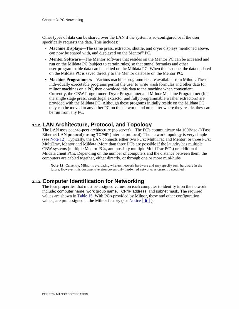
2.2.4.3. Mildata PC Without MultiTrac—If the system does not include MultiTrac, the Mildata PC typically uses Com 1 to communicate with the devices in the Mildata network, although this is configurable. The various components needed to adapt this port to the incoming serial link (e.g., gender converter, RS232-to-RS485 converter, wiring harness) are provided with the PC. The assembled components, as currently used, are shown in Figure 4. The last component in this group, and the one that the incoming Mildata serial link connects to is a 9 pin male DIN connector. A 9 pin female DIN connector and pins are provided in a bag with the PC, for field wiring. When the Mildata daisy chain is fabricated on site, the female DIN connector is wired to the end of daisy chain closest to the PC. Depending on the distance, the customer may want to fabricate an extension cable with the appropriate 9 pin DIN connectors on each end to run between this point and the PC.
Figure 4: Serial Link-To-Com Port Adapters on Mildata PC
Assembled Components Legend
1. Wire harness with 25-pin connector, one end (shown) and 9-pin male DIN connector, other end (not shown)
2. RS232-to-RS485 adapter 3. Gender converter 4. Com port on PC 5. Rear of Mildata PC
.
Chapter 2. System Connections (Serial Links)
PELLERIN MILNOR CORPORATION
2.2.4.4. Older Drynet (Dryer/Shuttle) Controller—Older dryer/shuttle controllers consist of a dedicated PC with Drynet software and some machine controls (i.e., Power switch, Start and Stop buttons for each dryer and shuttle) mounted in a free-standing cabinet. On these units, the Drynet serial link is connected directly to a com port on the Drynet PC in the same manner as described in Section 2.2.4.3 for a Mildata PC without MultiTrac.
2.2.4.5. Older Miltrac Controller—The older Miltrac is a microprocessor controller with a processor board similar to that used in machines (see Section 2.2.4.1 for PC Miltrac). The board contains serial ports accessed via MTA connectors the same as on the processor boards used by machines. As with machine processor boards, 1MTA32 is dedicated to Miltrac serial communication. However, on the Miltrac processor board, a second port: 1MTA33, is also dedicated to Miltrac communication, to speed communication in larger Miltrac systems. Miltrac controlled devices 0 through 19 must communicate with 1MTA32 and devices 20 through 39 must communicate 1MTA33 via a separate serial link. Note that regardless which port on the Miltrac processor board a device communicates with, the Miltrac serial port on the device's own board is always 1MTA32.
2.2.5. Troubleshooting Reminders for the “Daisy Chain” Method When troubleshooting communication problems in a system that uses daisy-chaining, the technician will often want to isolate certain devices for testing by disconnecting the serial link from the other devices. Remember that continuity in each of the two serial lines across the entire serial link is provided by the internal connections between pins 1 and 2 (serial low) and between pins 3 and 4 (serial high) on each board. As soon as you remove an MTA connector from the board, the link is broken not only to this machine but to all machines downstream of this connection point (on the side opposite the system controller). If you only want to remove one machine from the link, you must jumper pins 1 and 2 together and pins 3 and 4 together on the removed MTA connector so the downstream machines will remain connected.
3.1. Networking the PC's used in CBW® Systems Communication among the Mentor®, MultiTrac®, and Mildata® PC's via a LAN (local area network) is becoming increasingly important in CBW® tunnel systems. With the introduction of Milnor's MultiTrac® product and enhancements in Milnor software, the LAN's primary function has shifted from manual data backup to automated data sharing. Some of the latest MultiTrac and Mildata features require the PC's to be networked. For this reason, the PC's supplied by Milnor for Mentor, MultiTrac and Mildata applications—currently a Siemens PC with Windows® 2000 Professional pre-installed—is configured at the Milnor factory for networking. This document explains network setup for these PC's. If your installation uses any other PC/operating system combination (such as the AdvanTec PC, running Windows NT, as previously supplied by Milnor), contact Milnor Technical Support for networking assistance.
Notice 4 : Knowledge of Microsoft Windows Assumed—For an adequate understanding of the instructions that follow, the reader must be familiar with the use of PC's and with the newer Microsoft® Windows® operating systems. PC's used in Milnor CBW automated laundering systems currently use Windows 2000 Professional™.
3.1.1. What Types of Data are Shared Over the LAN? In new CBW system installations, certain types of data are automatically shared over the LAN; that is, the software expects this data to be accessible and uses it without any special setup procedures. This includes:
• Mentor Status and Error Messages—Mentor messages displayed on the Mentor PC are now displayed, in real time, on the MultiTrac PC as well. They are displayed on the PC Miltrac Main and Cake pages.
• Names—This includes the names of formulas, customers, drycodes, extract codes, goods codes and destinations. A “names” database resides on the MultiTrac PC and provides this data to the MultiTrac software. This database is automatically updated by the software where names are normally entered. For example, when a change is made to a formula name on the Mentor controller (CBW), this change is automatically sent to the “names” database.
• Production data—When the system includes both a MultiTrac controller and a Mildata PC, production data is collected by the Online Communicator software running on the MultiTrac PC, stored in a database on that PC and shared with the Mildata PC.
• Machine Displays—When the system includes both a MultiTrac controller and a Mildata PC, press, extractor, shuttle, and dryer display data is collected by the Online Communicator software running on the MultiTrac PC and shared with the Mildata PC.
Chapter 3. PC Networking
PELLERIN MILNOR CORPORATION
Other types of data can be shared over the LAN if the system is so-configured or if the user specifically requests the data. This includes:
• Machine Displays—The same press, extractor, shuttle, and dryer displays mentioned above, can now be shared with, and displayed on the Mentor® PC.
• Mentor Software—The Mentor software that resides on the Mentor PC can be accessed and run on the Mildata PC (subject to certain rules) so that tunnel formulas and other user-programmable data can be edited on the Mildata PC. When this is done, the data updated on the Mildata PC is saved directly to the Mentor database on the Mentor PC.
• Machine Programmers—Various machine programmers are available from Milnor. These individually executable programs permit the user to write wash formulas and other data for milnor machines on a PC, then download this data to the machine when convenient. Currently, the CBW Programmer, Dryer Programmer and Milnor Machine Programmer (for the single stage press, centrifugal extractor and fully programmable washer extractors) are provided with the Mildata PC. Although these programs initially reside on the Mildata PC, they can be moved to any other PC on the network, and no matter where they reside, they can be run from any PC.
3.1.2. LAN Architecture, Protocol, and Topology The LAN uses peer-to-peer architecture (no server). The PC's communicate via 100Base-T(Fast Ethernet LAN protocol), using TCP/IP (Internet protocol). The network topology is very simple (see Note 12): Typically, the LAN connects either two PC's: MultiTrac and Mentor, or three PC's: MultiTrac, Mentor and Mildata. More than three PC's are possible if the laundry has multiple CBW systems (multiple Mentor PC's, and possibly multiple MultiTrac PC's) or additional Mildata client PC's. Depending on the number of computers and the distance between them, the computers are cabled together, either directly, or through one or more mini-hubs.
Note 12: Currently, Milnor is evaluating wireless network hardware and may specify such hardware in the future. However, this document/version covers only hardwired networks as currently specified.
3.1.3. Computer Identification for Networking The four properties that must be assigned values on each computer to identify it on the network include: computer name, work group name, TCP/IP address, and subnet mask. The required values are shown in Table 15. With PC's provided by Milnor, these and other configuration values, are pre-assigned at the Milnor factory (see Notice 5 ).
Chapter 3. PC Networking
PELLERIN MILNOR CORPORATION
Table 15: Computer Identification Values for PC's in a CBW System (see Notice 5 )
Computer Computer
Name Work group
Name TCP/IP Address
Subnet Mask
1st (or only) Mentor PC Mentor1
Milnor
10.1.30.1
255.255.0.0
2nd Mentor PC Mentor2 10.1.30.2 3rd Mentor PC Mentor3 10.1.30.3 4th Mentor PC Mentor4 10.1.30.4 5th Mentor PC Mentor5 10.1.30.5 1st (or only) MultiTrac PC MultiTrac1 10.1.30.11 2nd MultiTrac PC MultiTrac2 10.1.30.12 3rd MultiTrac PC MultiTrac3 10.1.30.13 4th MultiTrac PC MultiTrac4 10.1.30.14 5th MultiTrac PC MultiTrac5 10.1.30.15 1st (or only) Mildata PC Mildata1 10.1.30.6 2nd Mildata PC Mildata2 10.1.30.7 3rd Mildata PC Mildata3 10.1.30.8 4th Mildata PC Mildata4 10.1.30.9 5th Mildata PC Mildata5 10.1.30.10
Notice 5 : Risk of network communication failure—In some older systems values other than those shown were manually entered. If newly installed equipment will be combined in a single LAN, with older equipment, or an older system is upgraded to new software, previously assigned values must be changed to those shown. Consult Milnor Technical Support. In most cases, the on-site technician need only install the network wiring and the LAN will function. However, the values shown above may need to be checked during troubleshooting. As of this writing, the procedures for accessing this data in the Windows® 2000 software are as follows (consult Windows® Help for more information):
For computer and work group names, right-click on the My Network Places icon, then select Properties, Advanced, Network Identification. On the System Properties window, select Network Identification. The computer name and work group name should be displayed.
For TCP/IP address and subnet mask, click Start, Settings, Network and Dialup Connections. Double-click on Local Area Connection, Properties. Select Internet Protocol (TCP/IP) and click Properties. The TCP/IP address and subnet mask values should be displayed.
When a Mentor, MultiTrac, or Mildata PC is set up at the Milnor factory, the setup procedure installs the following program in the location shown: C:\Installation Files\PCSetup\PCSetup.exe If any values must be corrected, run this program. The program provides a dialog box in which to select the PC's function (e.g., “Mentor”), it's number (e.g., “2” (Mentor #2)), and enter a customer name. The program will then assign the appropriate identification values for this PC—a more reliable approach than entering the values manually.
Chapter 3. PC Networking
PELLERIN MILNOR CORPORATION
3.1.4. LAN Wiring The Mentor and MultiTrac PC's are each housed in a cabinet that contains other control circuitry as well. Electrical conductors are exposed within the cabinet.
CAUTION 6 : Electrocution and Electrical Burn Hazards—Contact with electric power can kill or seriously injure you. Electric power is present inside the cabinetry unless the main machine power disconnect is off. • Abide by the current OSHA lockout/tagout standard when lockout/tagout is called for in
the service instructions. Outside the USA, abide by the OSHA standard in the absence of any other overriding standard.
• Do not service the machine unless qualified and authorized. You must clearly understand the hazards and how to avoid them.
The PC's currently provided by Milnor are network-ready. Network connections are made via the Ethernet (RJ45) receptacle on the rear of the PC, using CAT5 cabling. This cabling must be obtained locally, and if not pre-made, fabricated on site. Depending on the network topology, this may be either patch (straight-through) or crossover cabling. One or more RJ45 mini-hubs may also be required. The connectors and mini-hubs may be obtained locally or from Milnor. Milnor Kit number KXMDNTM001 contains one four-port mini-hub and a bag of connectors.
3.1.4.1. Determining the Wiring Scheme—Figure 5 shows various network wiring schemes and the conditions in which each would be used.
Figure 5: Common Network Wiring Schemes
Two Closely Positioned PC's Legend
1. CAT5 crossover cable 2. CAT5 patch (straight-through) cable 3. Signal booster, if required. Use for runs
exceeding 300 feet (91 meters). A mini-hub will serve this purpose.
4. Four-port, RJ45 mini-hub (must be connected to a power source).
Two Widely Separated PC's
Three or Four PC's
. More than four PC's can be connected by using two or more four-port mini-hubs. Additionally, larger capacity hubs, including stackable units are available.
As shown in Figure 5, observe the following rules when wiring the LAN: • When connecting two PC's directly (without a mini-hub) CAT5 crossover cable must be
used. When connecting any number of PC's through one or more mini-hubs, CAT5 patch (straight-through) cable must be used.
Chapter 3. PC Networking
PELLERIN MILNOR CORPORATION
• For runs exceeding 300 feet (91 meters), always use a signal booster. A mini-hub serves this purpose. The mini-hub must be connected to a power source. Refer to the instructions provided with the mini-hub for more information.
3.1.4.2. Obtaining/Fabricating the Cable—CAT5 cable consists of eight conductors (wires)—four twisted pairs. With patch (straight-through) cable the pin position of each conductor must be the same on both ends. With crossover cable, the positions of four of the wires are different on one end from the other. The connectors (plugs) are similar to those used on telephone cords, and a special crimping tool should be used to make the connections. Because there are eight small-gauge wires to thread into a small connector, stripping, threading and crimping the wires is tedious and error-prone. It is advisable to purchase prefabricated cable whenever possible. Many lengths of pre-fabricated cable are available from major PC component retailers, but these may have to be ordered in advance. As with other control wiring, it is advisable to use heavy-duty cabling. Patch (straight-through) cable must be wired so that the pins on each connector correspond (pin 1 on one end is connected to pin 1 on the other end, etc.). Crossover cable must be wired so that pin 1 on the standard end connects to pin 3 on the crossover end, pin 2 on the standard end connects to pin 6 on the crossover end, pin 3 on the standard end connects to pin 1 on the crossover end and pin 6 on the standard end connects to pin 2 on the crossover end. Pins 4, 5, 7, and 8 respectively, on the standard end connect to the same pins on the crossover end. A standard color scheme is used to identify the conductors in CAT5 cable. Table 16 provides a guide for fabricating the cable.
Table 16: CAT5 Cable Wiring Guide
Pin Number
Wire color on both ends of a patch (straight-through) cable or on one end of a crossover cable
Wire color on other end of a crossover cable
1 white/orange white/green 2 orange green 3 white/green white/orange 4 blue blue 5 white/blue white/blue 6 green orange 7 white/brown white/brown 8 brown brown
3.1.4.3. Running the Cable—Consult local codes to determine any requirement to run network cable within conduit and to ground the conduit. In the absence of such requirements, consider cable protection. Use care when pulling CAT5 cable. The individual conductors are much smaller gauge than those used in other control wiring and are more prone to breaking when the cable is pulled.
3.1.5. Testing and Troubleshooting Once the LAN is set up, verify that all PC's are communicating with the network. This can be done on any PC. With the Windows desktop visible (not hidden by any software windows), double-click on the My Network Places icon, then double-click Entire Network. You should see a selection named Milnor. This is the network (work group) name. Double-click on this selection. You should now see a window similar to that shown in Figure 6, containing the name of each PC
Chapter 3. PC Networking
PELLERIN MILNOR CORPORATION
on the network, including the PC you are working at. These are the applicable computer names listed in Table 15.
Figure 6: Part of Milnor Window Showing PC's In “Milnor” Network
Occasionally, the computer names will not appear here initially, even though the PC's are communicating with the network. If you do not see the names here, select Start, Search, For Files or Folders, Computer. For each computer that should be communicating with the network, enter its computer name (see Table 15).
Network problems can be divided into those that prevent the network from recognizing the PC as a resource and those that prevent data from being located, even though all PC's are represented on the network.
3.1.5.1. If a PC Is Not Represented As a Network Resource—Any PC not represented as a network resource in the Milnor window, is not communicating with the network. If no other PC's are displayed, this problem is probably with the PC you are on. If the network has more than two PC's, try accessing this information on another PC. Common problems are as follows:
3.1.5.1.1. Bad Cable Connections—The most likely culprits include faulty connectors, improperly wired cable, or a broken conductor. If the cable was fabricated on site, double check the wiring connections. Verify that the pins on the connectors are properly matched up with the wires and that the connectors were crimped with sufficient force to make good connections. If the cable was forcefully pulled while being installed, one or more of the wires may have broken. Check the continuity of each line with an ohmmeter.
3.1.5.1.2. Wrong Type of Cable—Patch (straight-through) and crossover cable cannot be interchanged. Each type of cable will only work under the conditions shown in Figure 5. Remember that if a signal booster (mini-hub) is subsequently added to an existing network that previously consisted of two directly-connected PC's, the crossover cabling must be discarded and replaced with patch (straight-through) cables.
3.1.5.1.3. Weak Signal—Signal integrity will be lost if the cable run is too great. If the length of the cable that connects a problem PC to the network is close to 300 feet (91 meters), it is advisable to add a signal booster on the possibility that the signal is being degraded. However, be sure to observe the information in Section 3.1.5.1.2.
3.1.5.1.4. Missing or Duplicate TCP/IP Addresses—Every PC on the network must be assigned a unique TCP/IP address. Milnor uses the convention shown in Table 15, as a convenient means of assuring this. Because these values are pre-assigned programmatically at the Milnor factory, it is unlikely that an address conflict will occur in a newly commissioned system. However, this is more likely if new equipment is combined with old, in an existing system. Check for, and resolve any address conflicts by manually changing the values to those shown in Table 15.
Chapter 3. PC Networking
PELLERIN MILNOR CORPORATION
3.1.5.2. If Data Is Not Locatable—If a Milnor software issues an error message indicating that certain data cannot be located, but you have determined that all PC's are communicating with the network, as explained above, likely problems include:
3.1.5.2.1. File or Program Deleted—Milnor software that reference external data, expect to find that data (files or programs) in certain locations on the network. In some cases, the location that the software looks to is configurable. If such data is moved, all references to it must be changed. If an error message appears, indicating that data cannot be located, copy down the message, then attempt to locate the referenced file or program on the network. Consult the documentation for the software in question. If you cannot determine how to restore the data or reconfigure the software, consult Milnor Technical Support.
3.1.5.2.2. Invalid Computer Name—Some software looks for data on the network by referencing a PC by name. If the name assigned to the PC is not the same as that listed in Table 15, the data will be unlocatable even though the PC itself is communicating with the network. Check for and correct any invalid computer names by running PCSetup.exe, as explained in Section 3.1.3.
3.1.5.2.3. Mismatched Port Addresses In Online Communicator and Mentor—As explained in Section 3.1.1, machine displays for other machines in the system can be displayed on the Mentor PC if the system includes a MultiTrac controller or a Mildata PC, or both. The Mentor PC gets this data from the Online Communicator software. This software resides on the MultiTrac PC if the system includes a MultiTrac controller, or on the Mildata PC, if not. The Mentor software accesses this data through a software port provided by the Online Communicator software. The Mentor software is told which port to communicate with via a Mentor configure value that defaults to the value 1025. Normally Online Communicator uses port number 1025. However, if a non-Milnor software that uses the same communication method is installed on the same PC and loads before Online Communicator, the Online Communicator software will automatically use the next available port (e.g., 1026). If communication with the Mentor software is lost, it can be regained by reconfiguring the Mentor software to use the new port number. To determine this port number, while the Online Communicator software is loaded (running), click on Online Communicator icon in the Windows Task Bar. A status window will appear and the port number will be displayed in it. Note, however, that the order in which the non-Milnor, and Online Communicator software load must not vary. Otherwise, the port number used by the Online Communicator software will continually change, resulting in ongoing, intermittent communication loss with the Mentor software.
3.1.5.2.4. Mismatched Port Addresses in Online Communicator and Mildata Client (Older Systems)—This problem applies to older systems that use one or more client Mildata PC's. On such systems, communication between the client Mildata software and the Online Communicator software can be lost in much the same way as explained in Section 3.1.5.2.3, above because the Mildata client software uses the port number assigned in a configure value. Beginning with Mildata software version 14100, potential communication problems have been eliminated because the newer software looks up the actual port number used by Online Communicator in that PC's registry. Should an older system experience such a communication problem, it is advisable to upgrade the Mildata software.
3.1.6. Sharing a Printer Over the Network It is likely that a printer will be connected to at least one of the PC's on the network. If so, the user can print from any PC to that printer if it is shared. This requires that 1) file and print sharing over the network is enabled, 2) the printer is explicitly shared on the host PC (the PC the printer is connected to), and 3) the printer (printer driver) is installed on every other PC you wish to print
Chapter 3. PC Networking
PELLERIN MILNOR CORPORATION
from. The basic procedure, as of this writing, is described below. Refer to Windows Help for more information.
File and print sharing was enabled as part of factory setup procedure. To verify this on any PC, double-click the My Network Places desktop icon, then right-click in the My Network Places window and select Properties. In the Network and Dial-up Connections window, double-click the Local Area Connection icon. In the Local Area Connection Status window, click the Properties button. In the Local Area Connection Properties window, the File and Print Sharing for Microsoft Networks selection must be enabled (checked).
To explicitly share a printer with other PC's, make the following selections on the host PC: Select Start, Settings, Printers. In the Printers window, right-click on the icon for the printer to be shared, and select Sharing... This will display the Properties window for this printer with the Sharing tab selected. Enable the Shared as: selection, leave the printer name at its default value and click the OK button.
To install the printer on a PC other than the host PC, select Start, Settings, Printers. In the Printers window, double-click the Add Printer icon to run the printer installation wizard and follow the instructions. When responding to the prompts, indicate that this is a network printer and find it by browsing to the host PC. Repeat this process on any other applicable PC's.
4.1. MultiTrac™ Overview MultiTrac reflects Milnor®'s ongoing shift toward the use of personal computers (PC's) in the control of automated laundering systems (see Note 13). As PC capabilities increase and costs decrease, significant economic and functional benefits can be realized by shifting supervisory activities (programming, monitoring, troubleshooting, and data collection) as well as certain control functions, from dedicated controllers to a centralized PC.
Note 13: Although this document refers to personal computers and uses the abbreviation “PC” throughout, the computers supplied by Milnor are actually industrial versions of PC's (IC's) that use a standard PC operating system and run PC-based software.
This direction can also be seen in Milnor's growing repertoire of custom, Windows-based PC products. Milnor continues to enhance its widely used data collection and productivity reporting product—Mildata®. More recently, Milnor introduced Drynet (Windows Dryer/Shuttle Controller)—a PC hardware/software package. Some of the most recent additions include the PC Miltrac™ and PC Device Master software. With these products, the functions performed by the Miltrac, Device Master and Drynet system controllers can now be combined in a single platform: MultiTrac. The MultiTrac hardware consists of an industrial PC (including monitor, keyboard, and mouse), enclosed in a cabinet to be placed on the production floor. The cabinet also houses any additional electronics needed by the various MultiTrac functional components. If Drynet is included, face plate controls for each dryer and shuttle are mounted on the MultiTrac cabinet, as they were on the older Dryer/Shutle controller cabinet. The MultiTrac PC is supplied with the PC operating system (currently, Microsoft Windows 2000) and at minimum, PC Miltrac software.
monitor, keyboard, and software). As with the older controller, MultiTrac with PC Miltrac software, provides the coordination and data-passing functions needed for system operation. PC Miltrac also provides enhanced supervisory capability over that of the older Miltrac software.
2. Optional Device Master—When PC Device Master software is included, this component replaces the dedicated Device Master controller (processor, monitor, keyboard, and software). As with the older controller, this component can be used to control conveyors for any of several specialized purposes, or for representing "phantom belts" or interfacing between Miltrac and allied dryers. PC Device Master provides enhanced supervisory capability over the older Device Master software.
Chapter 4. Supplemental Information
PELLERIN MILNOR CORPORATION
3. Optional Drynet (Windows Dryer/Shuttle Controller)—When Drynet is supplied with a new dryer installation, the LED displays and keypads normally provided in the belt box for each dryer and shuttle are omitted. All supervisory and manual operation functions that would otherwise be done using the machine's keypad and display can be performed with greater ease and clarity on Drynet. MultiTrac with Drynet software installed replaces the Drynet hardware/software product.
4. Single connection point for Mildata—In older Miltrac systems, if Mildata is used, a separate serial link must be run from the Mildata PC to each device. With MultiTrac, Mildata can be incorporated into the system, merely by networking the Mildata and MultiTrac PC's together.
4.1.2. The MultiTrac User Interface MultiTrac provides monitoring, manual operation, and intervention of shuttles, dryers, and related conveyors. (CBW's, presses and extractors will continue to be operated and monitored via the their own dedicated controllers.) At daily startup, MultiTrac will automatically load all installed software components. Although a user familiar with Windows type interfaces can use standard Windows techniques (e.g., ALT+TAB) to navigate the various software, MultiTrac will also provide several features to simplify monitoring and quickly display the data pertinent to the operator: 1. Load last screen—Used in conjunction with the Minimize main form at startup configure
decision, this configure decision causes the MultiTrac monitor at startup, to default to the software and data screen it last displayed at the previous day's shutdown. Once the operator's preferred screen is displayed, the operator will see this screen at subsequent startups without having to navigate to it.
2. Optional second monitor—MultiTrac can be provided with a second, strategically located, monitor. This monitor will display whatever data window was specified in the Miltrac Show pages in secondary monitor configure decision.
3. Easier operator interaction—Although the virtual keypad used in Drynet provides an interface that users of the older keypad controls can immediately relate to, some users will find the sequential mouse clicks cumbersome. Drynet for MultiTrac will provide a form-based alternative in which all valid choices are displayed and immediately selectable. Similarly, the sequential presentation of prompts when batch data verification is needed will be replaced with a form that lets the user see all data at once, randomly access any parameter, and bypass those with acceptable defaults.
4.1.3. MultiTrac As a Controller MultiTrac (with the required PC Miltrac software installed) coordinates the transfer of batches and associated batch data among the devices downstream of the tunnel (extraction device, shuttles, dryers and associated conveyors). MultiTrac must remain on with the PC Miltrac software running for the system to operate. Similarly, if the system has specialized conveyors or other devices that require the Device Master controller, the PC Device Master software must remain running to handle any conditions other than normal automatic operation (which is handled by the Device Master microprocessor).
Milnor dryers and shuttles depend only on their own dedicated controllers to operate. Hence, the Drynet software, if provided, need not be running. Similarly, the system is not dependent on Mildata to operate. However, the status of Drynet and Mildata can affect processing in the dryers. If Drynet is running, or the Mildata computer networked to MultiTrac is on and the Mildata software is running, the dryers will use the drying formulas programmed in Drynet or Mildata (these are the same, because Drynet and Mildata share the same Dryer Programmer software module and formula data file). If neither software is running, the dryers will use their internal
Chapter 4. Supplemental Information
PELLERIN MILNOR CORPORATION
formulas. This permits the formula developer to tweak the drying formulas at the MultiTrac or Mildata computer while the dryers are in operation and quickly see the results without actually committing to the changes. Once any changes are finalized, the developer can easily download the changes to the dryers. After downloading, the dryers' internal formulas will match those in Drynet and/or Mildata.
4.2. Construction of External Serial Link Cables This document provides information for on-site fabrication of certain types of serial communication cables. An individual machine can be connected to certain makes and models of serial printer (see Note 14) using the printer cable described in Section 4.2.2.2. Programmable data can be transferred between compatible machines or between a machine and a Milnor serial memory storage device (see Note 15), using the download cables described in Section 4.2.2.3 and Section 4.2.2.4 respectively. These cable(s) connect to the cabinet-mounted 9-pin DIN type receptacle shown in Figure 7 and may be installed temporarily or permanently, as appropriate.
If the machine is connected to a Mildata® or Drynet (dryer/shuttle controller) network (see Note 16), downloading is more likely to be handled by these products. Another Milnor document—Section 2.2. “On-Site Installation and Troubleshooting of Permanent Serial Communication Cables”—describes the permanent cables needed to communicate across a Mildata, Drynet, or Miltrac™, network. In the unlikely event that personnel will want to download data via the download cables described herein, rather than via Mildata, all energized machines on the Mildata network will receive the downloaded data. Turn off power to any machines to which you do not wish to download.
Note 14: The currently approved printers and printer configuration settings are provided in the related section in document BICWUI01. A pre-assembled machine-to-printer cable similar to the cable described here, is available from Milnor (P/N 10YMK2PNTR).
Note 15: The Milnor serial memory storage device (also known as a download box) contains nonvolatile memory to hold a back-up copy of the programming and configuration data for one machine. This data is transferred between the machine and the memory storage device via the DIN receptacle on the machine. Two models are currently available: KXMIC00507 and KXMIC00508. The already wired cable and DIN connector are included as part of the memory storage device. Consult the Milnor Service department to determine the correct device for a particular application.
Note 16: Mildata is Milnor's PC-based product for centralized data collection, productivity analysis, report generation, formula development and data downloading. Drynet permits supervisory and manual functions for a group of dryers and the shuttle that serves them to be performed from a central PC.
Applicable machines are provided with a single DIN receptacle for both downloading and printing. Only one function at a time (downloading or printing) can be performed using this connection.
4.2.1. Pin Identification The download and printing functions use different data communication lines, but the DIN receptacle on the machine contains all of the pins used for either function. Figure 7 illustrates the DIN receptacle (which uses male pins) and the mating plug (which uses female pin sockets), each viewed from the wire entry side. The receptacle is normally installed and wired at the Milnor factory. The plug and female pin sockets for customer use are provided in a bag inside the electric box. Table 17 shows the function of each pin.
Chapter 4. Supplemental Information
PELLERIN MILNOR CORPORATION
Figure 7: 9-Pin DIN Connector Pin Identification (from wire entry side of connectors)
Receptacle (uses male pins) Plug (uses female pin sockets)
Legend
A. Pin numbers molded into parts B. Heavy white lines terminated with dots indicate pins normally connected together at the Milnor
factory . Table 17: External Serial Link Pin Assignments
Pin Number Function
Receptacle Wiring (inside electrical enclosure)
Wire Number Color Code 1 Serial low DLL Blue and black 2 3 Serial high DLH Blue and red 4 5 Clear to send (used for printing only) CTS Blue and orange 6 Electronic ground 2G Blue and white 9 7 Transmit data (used for printing only) TXD Blue and orange
8 +5 volts DC (used for serial memory storage device only)
V1 Blue
CAUTION 7 : Risk of damage to electronic components—Pin 8 is only used to supply +5VDC power to the download box and will damage components in both devices if not properly connected • Never connect pin 8 to any other pin in the connector, a printer, or another machine.
4.2.2. How to Wire the Cables Because the DIN receptacle is wired to support different functions and because the data transferred across these cables can be corrupted by electrical noise, follow these instructions carefully.
Chapter 4. Supplemental Information
PELLERIN MILNOR CORPORATION
4.2.2.1. Cable Specifications—Multi-conductor shielded cable that meets the following minimum requirements must be used in the applications covered herein. Conforming cable may be purchased from Milnor (P/N 09V300A04S) or purchased from another source:
• Jacket: 600VAC insulation • Shielding: braided, tinned copper, minimum 85 percent coverage • Four conductors with these specifications:
» Conductive material: Tinned copper, 20 AWG » Insulation: 300VAC, color coded » Preferred colors: red, black, green and white
4.2.2.2. Connecting a Machine to a Printer for “Print Data”—Many Milnor microprocessor-controlled machines allow permanent or temporary connection of a serial printer for generating printed copies of formulas or status reports during operation. Figure 8 shows how to wire the machine-to-printer cable. Milnor has tested and approved certain printers for this application (see Note 14).
Figure 8: Wiring Diagram for Cable to Connect a Machine to a Printer
Receptacle Legend
A. Receptacle (with male pins). Pin functions are as follows: 5. Clear to send (CTS). 7. Transmit data (TXD) 6&9. Ground. This application only uses Pin 6. 1&2. Not used in this application 3&4. Not used in this application 8. Not used in this application. See caution statement 7 . B. Plug (with female pin sockets) C. Approved serial printer (see Note 14) D. Tie shield and spare conductor(s) on this end of cable to
ground. Leave unconnected on other end. Cable Wiring
.
4.2.2.3. Connecting Two or More Machines for Machine-to-machine Transfer—Figure 9 shows how to wire a cable to connect a bank of identical machines (the Figure 9 example shows connections for four machines) so that data programmed on one machine in the group can be downloaded to all other machines simultaneously. This cable is referred to as a daisy chain because it runs in segments from machine to machine, connecting all machines in the group.
Chapter 4. Supplemental Information
PELLERIN MILNOR CORPORATION
Figure 9: Wiring Diagram for Cable to Connect Two or More Machines
Receptacle On Each Machine Legend
A. Receptacle on machine (with male pins). Pin functions are as follows:
1&2. Serial low 3&4. Serial high 6&9. Ground 5&7. Not used in this application 8. Not used in this application. See caution statement 7 . B. Plug on cable (with female pin sockets) C. Connect together each segment of shield so that it has
continuity across entire daisy chain. D. Connect together each segment of an unused conductor so
that it has continuity across entire daisy chain. E. Tie shield and spare conductor(s) on one end of daisy chain to
ground. Leave unconnected on other end of daisy chain. Cable Wiring
. The internal connections on each receptacle (machine) between pins 1 and 2, 3 and 4, and 6 and 9 make it easier to wire the cable because it is not necessary to jumper these pins together on the cable. However, this also means that every plug on the daisy chain must be plugged into a receptacle. Otherwise, the serial low, serial high, and ground conductors will not have continuity across the entire daisy chain and some machines will not receive data.
Rules and details about downloading among machines are fully described in the programming section of the reference manual.
4.2.2.4. Connecting a Machine to a Serial Memory Storage Device—The cable used with the serial memory storage device (download box) available from Milnor, see Note 15, is permanently attached to the storage device. Cable fabrication, as shown in Figure 10, is not required except for replacing a damaged cable. The memory storage device is the only application in which the power conductor (Pin 8) is used.
Chapter 4. Supplemental Information
PELLERIN MILNOR CORPORATION
Figure 10: Wiring Diagram for Cable to Connect a Machine to a Serial Memory Storage Device
Receptacle Legend
A. Receptacle on machine (with male pins). Pin functions are as follows: 1&2. Serial low. This application only uses Pin 1. 3&4. Serial high. This application only uses Pin 3. 6&9. Ground. This application only uses Pin 9. 5&7. Not used in this application. 8. +5VDC. Provides power to memory storage device. B. Plug on cable (with female pin sockets) C. Memory storage device (front panel may be different) D. Tie shield on this end of cable to ground. Leave unconnected on other end.
Plug and Storage Device
.
The download device may be used with CBWs with the serial Miltron controller. On newer CBWs with the Mentor controller (and assuming Mildata is not used), data is downloaded to/from a diskette on the Mentor PC.