11
Z Z ChemGear™ LTM Probe Specifying and Installing LTM Probes in Flotation Banks/Cells and Pump Sumps Zeroday Enterprises, LLC January 20, 2013

ZZ ChemGear™ LTM Probe
Specifying and Installing LTM Probes in Flotation Banks/Cells and Pump Sumps
Zeroday Enterprises, LLCJanuary 20, 2013
Z ChemGear™ LTM ProbeZ
Zeroday Enterprises, LLCwww.zerodayllc.com | 9450 SW Commerce Circle Wilsonville, OR 97070 | 1 (503) 582-9067 2
Table of Contents 1. Introduction 3
2. Flotation Banks, Cells And Columns 3
3. Sumps 6
4. Ltm Probe Installation And Calibration Key Points 8
5. Probe calibration procedure 9

Z ChemGear™ LTM ProbeZ
Zeroday Enterprises, LLCwww.zerodayllc.com | 9450 SW Commerce Circle Wilsonville, OR 97070 | 1 (503) 582-9067 3
INTRODUCTIONLTM probes are typically installed in flotation banks, individual flotation cells or in pump sumps to provide consistent accurate pulp level measurement. This document provides best practice descriptions of proper probe installations for both flotation and sump monitoring applications with an attempt to explain why these guidelines and recommendations are made. Detailed LTM probe type and sizing specification guidelines are provided in the individual flotation and sump sections below.
While the information below attempts to cover a range of specification and installation circumstances, re-viewing your application specifics with Zeroday Enterprises or agents before ordering and installing is highly recommended.
FLOTATION BANKS, CELLS AND COLUMNSThis section describes the flotation probe sizing method for flotation cells-banks along with some key installation and operation points that will help ensure your LTM probe will provide good, reliable perfor-mance. Figures 1 and 2 are schematics of the probe showing the main probe component details and a flotation cell cutaway showing proper probe installation, respectively.
» A single LTM probe is installed wherever there is a flotation bank, cell or column level controller such as a dart or pinch valve that actively manages flotation pulp level. The LTM probe sends a pulp level signal that is utilized by the flotation cell level control system to maintain pulp level depth at setpoint.
» The LTM is a conductive probe so any non-conductive solids build up on the probe might reduce conductivity and negatively impact accurate pulp level monitoring. In the measuring pulp zone the mixing pulp continuously cleans the probe so measurement issues rarely occur. However, above the froth lip solids build up on the probe might impact monitoring accuracy, so most flotation cell LTM probes are mechanically deadened at the manufacturer from the froth lip height to the electronic head.
» The active measuring zone is immediately below the mechanically deadened section which is also called the ‘Reduced Measuring’ range (RM).
» A black line demarks the bottom of the mechanically deadened RM length. This line will be vertically positioned at the froth lip elevation (height) during installation.
Electronic head
MechanicallyProbe DeadBracket
Reduced Measuring (RM)
Bushing/holder
Figure 1: Compact LTM Probe Version, Reduced Measuring

Z ChemGear™ LTM ProbeZ
Zeroday Enterprises, LLCwww.zerodayllc.com | 9450 SW Commerce Circle Wilsonville, OR 97070 | 1 (503) 582-9067 4
» Actual pulp level measurement is in the RM range below the froth lip height. At the bottom of the bracket is a 70 mm polypropylene bushing to hold the bottom end of the probe steady as well as electronically isolate the probe from the metal bracket. There is no level measurement in the bushing. Therefore actual maximum possible measuring length is actually RM length-70 mm.
» The probe is calibrated to set the 4 ma bottom and 20 ma top signal range during installation. At minimum the 4 ma setpoint must be 70 mm from the probe bottom end (just above bushing) and at maximum the 20 ma full signal set at the top of the RM section (at the froth lip).
» The are situations when the normal pulp variability range will not extend to the froth cell lip height and in some operations potential extraneous readings can occur where there is inconsistent probe surface washing/cleaning from the pulp; in these situations, during the calibration process the upper portion of the RM range can be electronically deadened during the calibration process by setting the 20 ma signal point at the level required. To avoid potential probe instability issues, only a MAXIMUM 30% of the entire RM section can be electronically deadened.
70 mm (2.75 inch)
Figure 2: LTM Probe Flotation Cell Installation
Bracket
Pulp level
RM, measure range
LTM Probe
Probe length
Figure 2: LTM Probe Flotation Cell Installation

Z ChemGear™ LTM ProbeZ
Zeroday Enterprises, LLCwww.zerodayllc.com | 9450 SW Commerce Circle Wilsonville, OR 97070 | 1 (503) 582-9067 5
» This electronic deadening is explained by the following example: For a 1 meter probe (1000 mm) where the top 300 mm section is mechanically deadened by the manufacturer, the RM is 700 mm. Consequently a maximum 700 * 0.3 = 210 mm of the RM can be electronically deadened. When calibrating the probe, 70 mm of the bottom end of the probe in the bushing will be deadened which means 210-70 = 140 mm can be electronically deadened at the top (below the froth lip).
» When shipped the active measuring range is set from the bottom of the mechanically dead-ened section (20 ma) and just above the probe bushing (4 ma). If the application requires that the top measuring height be below the froth lip, this can be set during installation.
» The LTM probe is fixed via the probe bracket shipped with the probe to the flotation cell at a single attachment point above the cell. Typically bolting the probe bracket to a supporting structure steel member above the cell is most effective. Often the probe is placed at or right next to the posi-tion where the existing level monitoring device is located. Alternatively install a solid strut or brace to which the probe bracket can be firmly attached to minimize probe movement in the pulp.
» Probe length sizing process is fairly simple and straightforward:
• Establish the expected operating froth depth range that represents statistically a 2σ or 95% confi-dence range. Then divide that range by 0.8 to ensure the active measuring range will be sufficiently long to cover the full pulp level variations expected. At the same time, probe must not extend to the flotation cell impeller depth and in general must be located above the most turbulent cell mixing zone. This defines the RM section length.
• Determine location and height above the froth lip of the probe attachment brace. There is no predetermined attachment point on the probe bracket so there is some latitude in positioning the probe vertically to accommodate site conditions. Determine where the bracket will be attached and measure from the head height to the froth lip (MD).
• Calculate required minimum total probe length (L’) as follows:
L’ = MD + RM + 70 mmwhere L’ = minimum probe length required, mm
MD = mechanical deadened lengthRM = reduced measurement range from bushing to froth lip
Also = 2σ/0.8
Z ChemGear™ LTM ProbeZ
Zeroday Enterprises, LLCwww.zerodayllc.com | 9450 SW Commerce Circle Wilsonville, OR 97070 | 1 (503) 582-9067 6
• Standard probe lengths come in 500 mm increments up to 3 meters, consequently the specified probe length specified will be L’ rounded up to the next 500 mm increment. Any additional length from rounding up will be adjusted in the MD length.
» Accurate pulp level measurements are obtained as low as 1 μS (micro siemens) so the probe operates fairly robustly in scaling conditions and when some solids buildup on the conductive measuring probe (in RM range). If scale does build up over time, the scale must be removed with acid periodically to ensure optimal probe measurements. While sol-ids may dry on RM probe section, these will be ‘cleaned’ by the circulating slurry; upon ini-tial cell startup the probe may experience a little insensitivity until the probe is ‘cleaned’.
» Standard probe material of construction is 316 stainless steel. In cases of high chlo-ride levels or where the chemical conditions make 316 stainless incompatible, probes con-structed with Hastelloy C-4 can be supplied but this is at significantly higher cost.
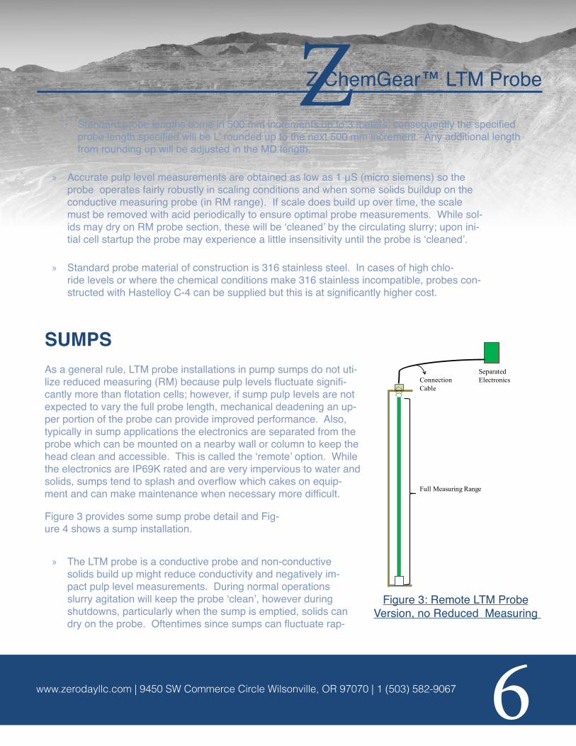
SUMPSAs a general rule, LTM probe installations in pump sumps do not uti-lize reduced measuring (RM) because pulp levels fluctuate signifi-cantly more than flotation cells; however, if sump pulp levels are not expected to vary the full probe length, mechanical deadening an up-per portion of the probe can provide improved performance. Also, typically in sump applications the electronics are separated from the probe which can be mounted on a nearby wall or column to keep the head clean and accessible. This is called the ‘remote’ option. While the electronics are IP69K rated and are very impervious to water and solids, sumps tend to splash and overflow which cakes on equip-ment and can make maintenance when necessary more difficult.
Figure 3 provides some sump probe detail and Fig-ure 4 shows a sump installation.
» The LTM probe is a conductive probe and non-conductive solids build up might reduce conductivity and negatively im-pact pulp level measurements. During normal operations slurry agitation will keep the probe ‘clean’, however during shutdowns, particularly when the sump is emptied, solids can dry on the probe. Oftentimes since sumps can fluctuate rap-
SeparatedConnection ElectronicsCable
Full Measuring Range
Figure 3: Remote LTM Probe Version, no Reduced MeasuringFigure 3: Remote LTM Probe
Version, no Reduced Measuring

Z ChemGear™ LTM ProbeZ
Zeroday Enterprises, LLCwww.zerodayllc.com | 9450 SW Commerce Circle Wilsonville, OR 97070 | 1 (503) 582-9067 7
Oftentimes since sumps can fluctuate rapidly, particularly upon startup, it is ad-vised that the probes be washed down to make them immediately respon-sive to pulp levels; versus waiting for the slurry to ‘clean’ the probe.
» The LTM probe bracket is installed in the sump via an installed bracket/strut. Probe positioning:
• End of probe bracket should be extended to just above the sump discharge pipe.
• Locate the probe away from the sump feed pipe(s) to minimize splashing on the probe and to ob-tain accurate pulp level measurements.
» Probe length sizing process is fairly simple and straightforward:
• Measure the depth from the top of the sump wall to the top of the sump discharge pipe. If the sump bottom is sloped and it is not possible to locate the probe near the discharge pipe, measure the depth to the sump bottom if that is above the discharge pipe (this will be H’).
• As referenced in the flotation installation instructions, there is no predetermined attachment point on the probe bracket so there is some latitude positioning the probe vertically.
• Standard probe lengths come in 500 mm increments, round up H’ to the next 500 mm increment. This will be the specified probe length required for optimum operation.
Figure 3: LTM Probe SumpInstallation
Z ChemGear™ LTM ProbeZ
Zeroday Enterprises, LLCwww.zerodayllc.com | 9450 SW Commerce Circle Wilsonville, OR 97070 | 1 (503) 582-9067 8
» Accurate pulp level measurements are obtained at conductivity levels as low as 1 μS (micro siemens) so probe operation is robust in scaling conditions and when sol-ids cake and buildup on the probe. If scale does build up over time, the scale must be removed with acid periodically to ensure optimal probe measurements.
» Solids that might have dried on the probe during shutdowns will be washed away by agitat-ing slurry upon startup; however there could be a little insensitivity during the initial period un-til the probe is ‘cleaned’. Based on operational experiences it is recommended that the sump probes be washed down prior to restarts so the probe is immediately responsive upon startup. Further it is recommended to also periodically wash down the upper exposed part of the probe where there is a tendency for solids caking when agitating slurry does not wash off the solids.
» Standard probe material of construction is 316 stainless steel. In cases of high chlo-ride levels or where the chemical conditions make 316 stainless incompatible, probes con-structed with Hastelloy C-4 can be supplied but this is at significantly higher cost.
LTM PROBE INSTALLATION AND CALIBRATION KEY POINTS
» INSTALLATION
Please follow the general installation guidelines and pointers below:
• Ensure the bracket is properly grounded to the threaded part of the probe. The bracket is a long ‘C’ bracket type where the threaded probe top is screwed into the top portion of the bracket (see diagram).
• Ensure the probe is not short circuited to the bracket anywhere. Only contact will be at the top where the electronics head is screwed into the metal bracket. The probe end sets in a polypropyl-ene fitting to electrically isolate the probe.
• Ensure probe mounting so the probe’s measuring zone is positioned to monitor the full pulp level range (as defined in specifying the probe during design). This is particularly important for probes that have a ‘Reduced Measuring’ (RM) range which will be explained further in the flotation applica-tion section below.
• The probes are setup specific to customer’s configuration in the bracket. For RM probes, the top measuring height is identified with a black “ring” on the probe, which is the calibrated 20 mA point with the 4 mA position located at the top of the polypropylene footer fitting.
Z ChemGear™ LTM ProbeZ
Zeroday Enterprises, LLCwww.zerodayllc.com | 9450 SW Commerce Circle Wilsonville, OR 97070 | 1 (503) 582-9067 9
• Calibrate the LTM probe when installed and in position. Normally only the sensitivity is adjusted to meet the specific application requirements.
PROBE CALIBRATION PROCEDUREWhen installed the probe must be calibrated in order to establish/set the probe’s operating range. The calibration procedure is as follows:
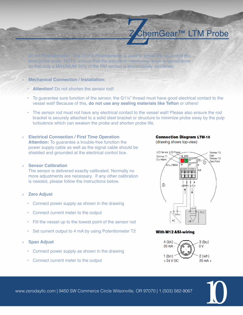
» Open the lid of the electronics head (on top end of standard probe, in separate remote box on probe remote version) and find the following terminals: Green LED light will lite when 24 VDC is applied to the brown wire (Terminal 1 from left) and 0 VDC to the blue wire (Terminal 2 from left). Please note that if on ASI electronics, the core colors may vary.
» Standard configuration with M12 plug:
• 24 VDC – Brown
• 0 VDC – Blue
• + Analog – White
• - Analog - Black
» Red LED: This is the sensitivity LED. At start up, if there is no liquid present, this LED should be off. During normal operation and setup with liquid present, this LED should be flashing on and off at the same frequency when the bottom end of the probe is in contact with the liquid. This may vary with a change in liquid level. If this is not the case, faulty readings will be seen.
» Sensitivity Potentiometer: The sensitivity potentiometer is used to adjust the probe for the correct sensitivity setting. By adjusting this potentiometer, the Red LED will re-act to the adjustment, therefore this potentiometer can be used to adjust for op-timal setup and to achieve the LED flashing as mentioned above.
» 4 mA Potentiometer: This potentiometer is used to adjust the 4 mA scale of the level probe. In this type of installation the 4mA will always be at the bottom end of the probe. The 4 mA and 20 mA on a probe cannot be reversed. Should you require the signal to be reversed, the probe has to be ordered in this manner.
Z ChemGear™ LTM ProbeZ
Zeroday Enterprises, LLCwww.zerodayllc.com | 9450 SW Commerce Circle Wilsonville, OR 97070 | 1 (503) 582-9067 10
» 20 mA Potentiometer: The 20 mA Potentiometer is used to adjust the top end of the level probe scale. NOTE: ensure that the electronic measuring range is turned down so that only a MAXIMUM 30% of the RM section is electronically deadened.
» Mechanical Connection / Installation:
• Attention! Do not shorten the sensor rod!
• To guarantee sure function of the sensor, the G1½” thread must have good electrical contact to the vessel wall! Because of this, do not use any sealing materials like Teflon or others!
• The sensor rod must not have any electrical contact to the vessel wall! Please also ensure the rod bracket is securely attached to a solid steel bracket or structure to minimize probe sway by the pulp turbulence which can weaken the probe and shorten probe life.
» Electrical Connection / First Time Operation Attention: To guarantee a trouble-free function the power supply cable as well as the signal cable should be shielded and grounded at the electrical control box.
» Sensor Calibration The sensor is delivered exactly calibrated. Normally no more adjustments are necessary. If any other calibration is needed, please follow the instructions below.
» Zero Adjust
• Connect power supply as shown in the drawing
• Connect current meter to the output
• Fill the vessel up to the lowest point of the sensor rod
• Set current output to 4 mA by using Potentiometer T2
» Span Adjust
• Connect power supply as shown in the drawing
• Connect current meter to the output
Z ChemGear™ LTM ProbeZ
Zeroday Enterprises, LLCwww.zerodayllc.com | 9450 SW Commerce Circle Wilsonville, OR 97070 | 1 (503) 582-9067 11
• Fill the vessel up to the maximum level
• Use span Potentiometer T3 to set the current output to 20 mA Please notice the maximum turn down rate is 70 % of the rod length! (e.g. Rod length 1000 mm: max. turndown to 700 mm)
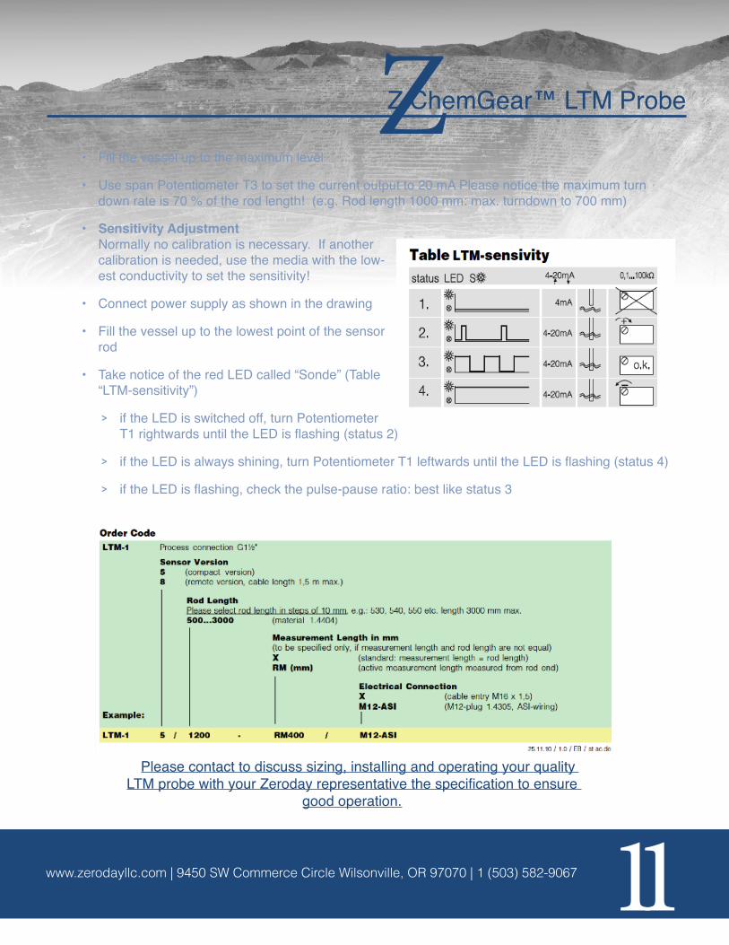
• Sensitivity Adjustment Normally no calibration is necessary. If another calibration is needed, use the media with the low-est conductivity to set the sensitivity!
• Connect power supply as shown in the drawing
• Fill the vessel up to the lowest point of the sensor rod
• Take notice of the red LED called “Sonde” (Table “LTM-sensitivity”)
> if the LED is switched off, turn Potentiometer T1 rightwards until the LED is flashing (status 2)
> if the LED is always shining, turn Potentiometer T1 leftwards until the LED is flashing (status 4)
> if the LED is flashing, check the pulse-pause ratio: best like status 3
Please contact to discuss sizing, installing and operating your quality LTM probe with your Zeroday representative the specification to ensure
good operation.


![INDEX [] LG-1550 LIEBHERR LTM 1500 LIEBHERR LTM-1400 LIEBHERR LTM-1225 LIEBHERR LTM-1220 LIEBHERR ... Cranes_over100tons.pdf](https://static.documents.pub/doc/80x56/5b07232e7f8b9ae9628e08fa/index-lg-1550-liebherr-ltm-1500-liebherr-ltm-1400-liebherr-ltm-1225-liebherr.jpg)


