The Company is pleased to announce continued outstanding results from the 2018 drilling program at its Redmoor Tin-Tungsten Project, being undertaken through its 50% owned joint venture vehicle Cornwall Resources Limited (“CRL”). In addition, these results include exceptional ‘Spectacular’ style assays just received from the lab for the first hole of the Phase 2 program (CRD028). Highlights • Outstanding ‘Spectacular’ style intercepts of up to 29.68% and 13.15% tin equivalent for the first hole of the Phase 2 program (CRD028). • These results are the highest-grade intercepts yet drilled and reinforces the caliber of the drill campaign and the high-grade of the Redmoor project overall. • Assay results from four further holes in the Redmoor 2018 program provide continued evidence of the high- grade zones within the Sheeted Vein System (SVS), highlights of which are: o CRD028: 6.56 m@ 3.30% Sn Eq from 459.41 m, including 1.22 m @ 15.55% Sn Eq o CRD028: 12.01 m @ 1.84% Sn Eq from 493.16 m, including 0.75 m @ 13.15% Sn Eq o CRD028: 7.99 m @ 3.45% Sn Eq from 543.61 m, including 0.70 m @ 29.68% Sn Eq o CRD027: 9.10 m @ 1.15% Sn Eq from 442.02 m, including 1.00 m @ 4.17% Sn Eq o CRD026: 10.31 m @ 1.17% Sn Eq from 518.60 m, including 1.62 m @ 3.25% Sn Eq o CRD026: 5.00 m @ 2.95% Sn Eq from 537.00 m, including 2.00 m @ 4.75% Sn Eq o CRD025: 11.00 m @ 1.10% Sn Eq from 277.15 m, including 2.10 m @ 3.00% Sn Eq • These results provide further confirmation of improving grades at depth at Redmoor. • The Phase 2 program has progressed rapidly, with four holes now complete (CRD028 to CRD031). • Additional hole planned – the efficiency of the CRL Team has allowed one supplementary hole (CRD032) to be added to the Phase 2 program, funded from within the current budget. We expect this hole to further boost the potential for resource growth. • Drilling of the additional hole, CRD032, is expected to complete during December. Following this, and the receipt of assay results, CRL plans to carry out an update to its Inferred mineral resource in Q1 2019. • Final Results from the Phase 2 drilling are likely to be available in early Q1 2019. • In preparation for a future Pre-Feasibility Study, and to add to existing testwork data, preliminary ore characterisation metallurgical testwork on samples from Redmoor, has commenced. Spectacular Grade Intercepts at Redmoor Tin-Tungsten Project ASX Release | 27 November 2018 For personal use only
Transcript
The Company is pleased to announce continued outstanding results from the 2018 drilling program at its
Redmoor Tin-Tungsten Project, being undertaken through its 50% owned joint venture vehicle Cornwall
Resources Limited (“CRL”). In addition, these results include exceptional ‘Spectacular’ style assays just received
from the lab for the first hole of the Phase 2 program (CRD028).
Highlights
• Outstanding ‘Spectacular’ style intercepts of up to 29.68% and 13.15% tin equivalent for the first hole of the
Phase 2 program (CRD028).
• These results are the highest-grade intercepts yet drilled and reinforces the caliber of the drill campaign and
the high-grade of the Redmoor project overall.
• Assay results from four further holes in the Redmoor 2018 program provide continued evidence of the high-
grade zones within the Sheeted Vein System (SVS), highlights of which are:
o CRD028: 6.56 m@ 3.30% Sn Eq from 459.41 m, including 1.22 m @ 15.55% Sn Eq
o CRD028: 12.01 m @ 1.84% Sn Eq from 493.16 m, including 0.75 m @ 13.15% Sn Eq
o CRD028: 7.99 m @ 3.45% Sn Eq from 543.61 m, including 0.70 m @ 29.68% Sn Eq
o CRD027: 9.10 m @ 1.15% Sn Eq from 442.02 m, including 1.00 m @ 4.17% Sn Eq
o CRD026: 10.31 m @ 1.17% Sn Eq from 518.60 m, including 1.62 m @ 3.25% Sn Eq
o CRD026: 5.00 m @ 2.95% Sn Eq from 537.00 m, including 2.00 m @ 4.75% Sn Eq
o CRD025: 11.00 m @ 1.10% Sn Eq from 277.15 m, including 2.10 m @ 3.00% Sn Eq
• These results provide further confirmation of improving grades at depth at Redmoor.
• The Phase 2 program has progressed rapidly, with four holes now complete (CRD028 to CRD031).
• Additional hole planned – the efficiency of the CRL Team has allowed one supplementary hole (CRD032) to
be added to the Phase 2 program, funded from within the current budget. We expect this hole to further
boost the potential for resource growth.
• Drilling of the additional hole, CRD032, is expected to complete during December. Following this, and the
receipt of assay results, CRL plans to carry out an update to its Inferred mineral resource in Q1 2019.
• Final Results from the Phase 2 drilling are likely to be available in early Q1 2019.
• In preparation for a future Pre-Feasibility Study, and to add to existing testwork data, preliminary ore
characterisation metallurgical testwork on samples from Redmoor, has commenced.
Spectacular Grade Intercepts at Redmoor Tin-Tungsten Project
ASX Release | 27 November 2018
For
per
sona
l use
onl
y
27 November 2018
2
Technical Director Neil Hutchison commented: “These results are outstanding and have exceeded expectations,
with grades of up to 29.68% Sn Eq, the drilling has been successful in extending and increasing the grades of the
known mineralisation beyond the existing resource model. Distribution of the various metals is demonstrating
zonation within the structure, which is typical of large mineralised systems supporting the upside potential of the
project. The joint venture agreed to incorporate another drill hole into the program which is expected to contribute
to the planned resource upgrade as the CRL team have demonstrated success by extending known mineralisation
beyond the existing resource model. On receipt of all assay results, expected early in 2019, a resource upgrade will
be performed, with the aim of significantly extending the current high-grade resource. As the drilling continues NAE
will continue to update the market as assay results are received.”
Introduction
2018 DRILLING PROGRAM
In June 2018, CRL began this year’s Phase 1 drilling program, aimed at further increasing the tonnage and grade
of the high-grade tin-tungsten-copper resource within the Sheeted Vein System at its Redmoor Project, which
presently stands at an Inferred Resource of 4.5 Mt @ 1.0% Sn Eq1. The seven-hole Phase 1 program was funded
by SML and NAE having contributed £332,000 each.
Assay results for the first two holes, CRD021 and CRD022, were reported on 20 September. Results for the next
two holes, CRD023 and CRD024, were reported on 4 October.
The remaining holes (CRD025, CRD026 and CRD027) of the Phase 1 program are reported herein, together with
the first hole of the Phase 2 program (CRD028).
Four holes (CRD028, CRD029, CRD030, and CRD031) have been drilled as Phase 2 of the 2018 drill program. Due
to rapid progress made, a further hole, CRD032 has been added to the Phase 2 program, aimed at further
extending the Redmoor high-grade resource in the open down-dip direction.
REDMOOR GEOLOGY OVERVIEW
Sheeted Vein System (SVS)
The SVS is a body in which numerous closely-spaced sub-parallel veins carry high-grade tin, tungsten and copper
mineralisation. The SVS strikes at approximately 070° and dips at approximately 70° to the north. The SVS has a
strike continuity of over 650 m with a thickness of approximately 100 m, and a variable known dip extent (250 –
450 m). The SVS is open down-dip over much of its length. Within this volume are a series of discrete high-grade
zones, sub-parallel to the overall SVS envelope. The 2018 drilling was designed to test this high-grade material,
and all the holes of the Phase 1 program have successfully intersected it. The 2018 resource contained eight
volumes in this high-grade material ranging from 135,000 t to 1,200,000 t (at a density of 2.9 g/cm3). Distribution
of the various metals is demonstrating zonation within the structure. Tin is richer in the western parts, tungsten
to the east and at depth and copper is typically richer higher in the system. All metals overlap to some degree
and is typical of large mineralised systems supporting the upside potential of the project.
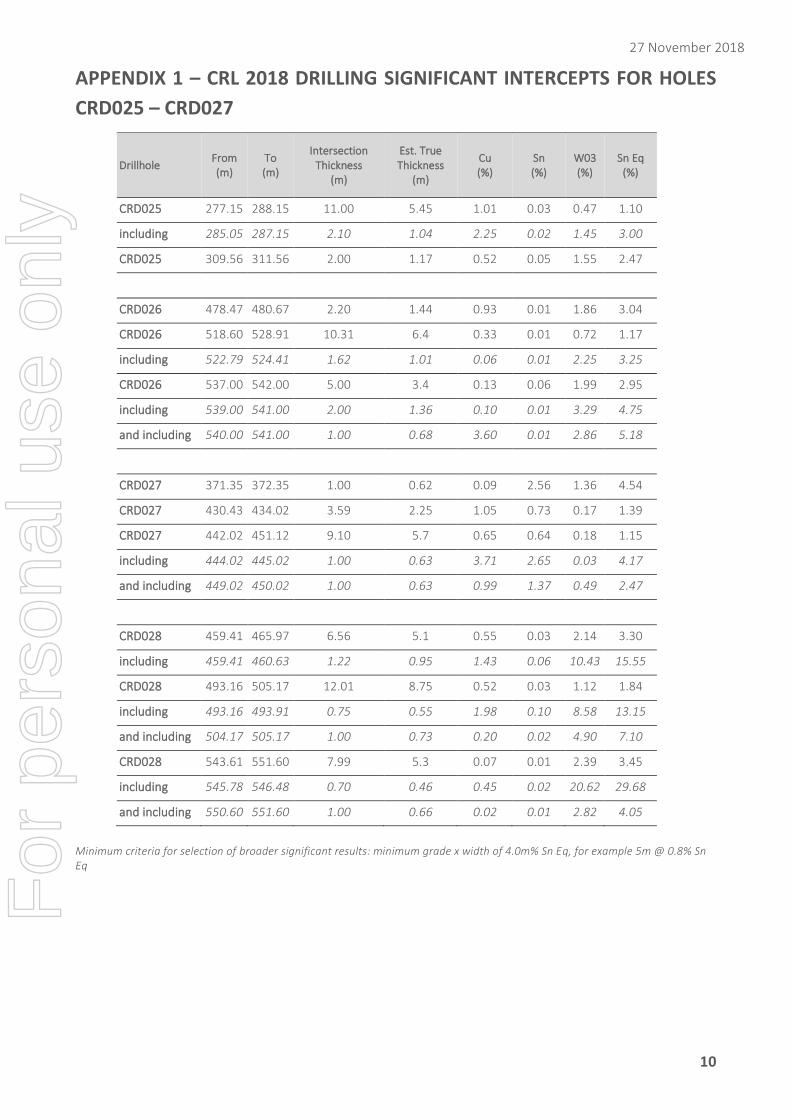
Further high grade tin, tungsten assays A summary of the significant intercepts for holes CRD025, CRD026, CRD027, and CRD028, is provided below with
details shown in Appendix 1. The tin equivalent calculation and basis for thicknesses is provided in the footnote2
below, and later in this document under ‘Note on calculation of Sn equivalent values and supporting recovery
data’:
CRD028
A summary of the significant intercepts in CRD028 is provided below:
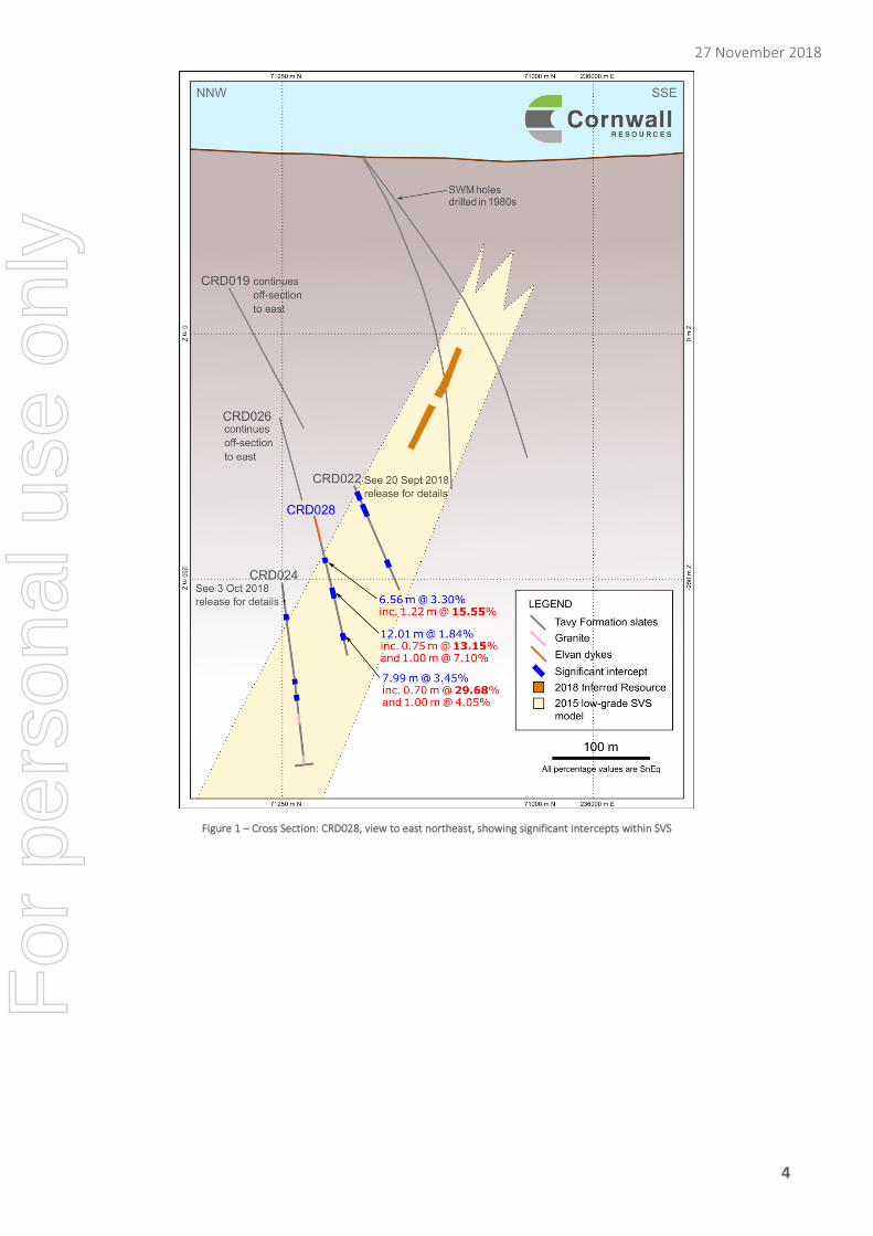
◦ 6.56 m@ 3.30% Sn Eq from 459.41 m, including 1.22 m @ 15.55% Sn Eq
◦ 12.01 m @ 1.84% Sn Eq from 493.16 m, including 0.75 m @ 13.15% Sn Eq and 1.00 m @ 7.10% Sn Eq
◦ 7.99 m @ 3.45% Sn Eq from 543.61 m, including 0.70 m @ 29.68% Sn Eq and 1.00 m @ 4.05% Sn Eq
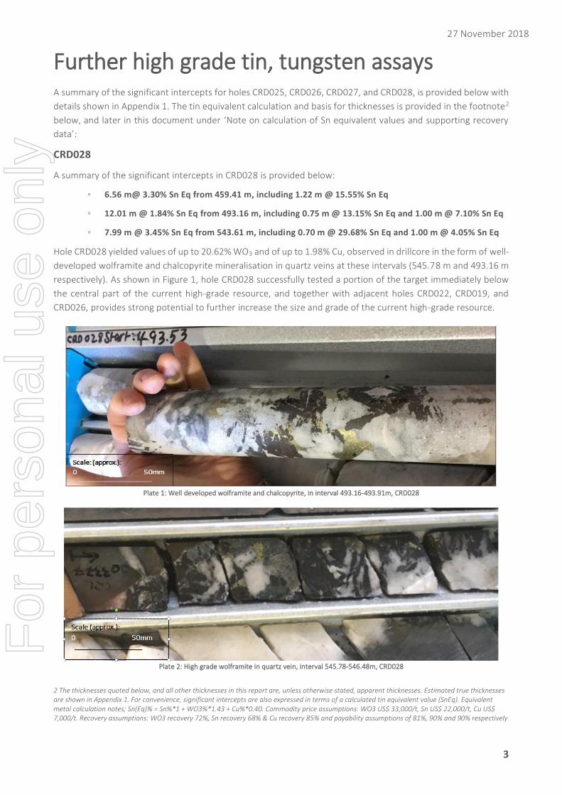
Hole CRD028 yielded values of up to 20.62% WO3 and of up to 1.98% Cu, observed in drillcore in the form of well-
developed wolframite and chalcopyrite mineralisation in quartz veins at these intervals (545.78 m and 493.16 m
respectively). As shown in Figure 1, hole CRD028 successfully tested a portion of the target immediately below
the central part of the current high-grade resource, and together with adjacent holes CRD022, CRD019, and
CRD026, provides strong potential to further increase the size and grade of the current high-grade resource.
Plate 1: Well developed wolframite and chalcopyrite, in interval 493.16-493.91m, CRD028
Plate 2: High grade wolframite in quartz vein, interval 545.78-546.48m, CRD028
2 The thicknesses quoted below, and all other thicknesses in this report are, unless otherwise stated, apparent thicknesses. Estimated true thicknesses are shown in Appendix 1. For convenience, significant intercepts are also expressed in terms of a calculated tin equivalent value (SnEq). Equivalent metal calculation notes; Sn(Eq)% = Sn%*1 + WO3%*1.43 + Cu%*0.40. Commodity price assumptions: WO3 US$ 33,000/t, Sn US$ 22,000/t, Cu US$ 7,000/t. Recovery assumptions: WO3 recovery 72%, Sn recovery 68% & Cu recovery 85% and payability assumptions of 81%, 90% and 90% respectively
For
per
sona
l use
onl
y
27 November 2018
4
Figure 1 – Cross Section: CRD028, view to east northeast, showing significant intercepts within SVS
For
per
sona
l use
onl
y
27 November 2018
5
CRD027
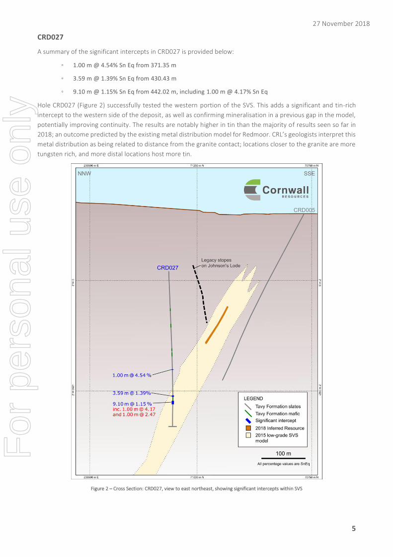
A summary of the significant intercepts in CRD027 is provided below:
◦ 1.00 m @ 4.54% Sn Eq from 371.35 m
◦ 3.59 m @ 1.39% Sn Eq from 430.43 m
◦ 9.10 m @ 1.15% Sn Eq from 442.02 m, including 1.00 m @ 4.17% Sn Eq
Hole CRD027 (Figure 2) successfully tested the western portion of the SVS. This adds a significant and tin-rich
intercept to the western side of the deposit, as well as confirming mineralisation in a previous gap in the model,
potentially improving continuity. The results are notably higher in tin than the majority of results seen so far in
2018; an outcome predicted by the existing metal distribution model for Redmoor. CRL’s geologists interpret this
metal distribution as being related to distance from the granite contact; locations closer to the granite are more
tungsten rich, and more distal locations host more tin.
Figure 2 – Cross Section: CRD027, view to east northeast, showing significant intercepts within SVS
For
per
sona
l use
onl
y
27 November 2018
6
CRD026
A summary of the significant intercepts in CRD026 is provided below:
◦ 2.20 m @ 3.04% Sn Eq from 478.47 m
◦ 10.31 m @ 1.17% Sn Eq from 518.60 m, including 1.62 m @ 3.25% Sn Eq
◦ 5.00 m @ 2.95% Sn Eq from 537.00 m, including 2.00 m @ 4.75% Sn Eq
Hole CRD026 (Figure 3) successfully intersected mineralisation down-dip of both the existing resource and
CRD019. It intersected strong tungsten grades that add further evidence for the trend of increasing grade with
depth, and for the presence of a tungsten-rich zone underlying the upper tin-rich zone.
For
per
sona
l use
onl
y
27 November 2018
7
CRD025
A summary of the significant intercepts in CRD025 is provided below:
◦ 11.00 m @ 1.10% Sn Eq from 277.15 m, including 2.10 m @ 3.00% Sn Eq
◦ 2.00 m @2.47% Sn Eq from 309.56 m
As shown in Figure 3, hole CRD025 successfully tested the gap between the existing inferred resource and
CRD019, the deepest high-grade hit of 2017 (see figure 1). As expected by CRL’s geologists, based on their
developing understanding of metal zonation and distribution at Redmoor, CRD025 proved tungsten-rich and also
had notable copper content.
Figure 3 – Cross Section: CRD025 and CRD026, view to east northeast, showing significant intercepts within SVS
For
per
sona
l use
onl
y
27 November 2018
8
PHASE 2 DRILLING AND FIFTH HOLE
CRL announced on 4 October that it planned to initiate Phase 2 of the drill program, consisting of a minimum of
four holes. These holes; CRD028, CRD029, CRD030, and CRD031 have been successfully completed ahead of
schedule and under budget. A fifth hole (CRD032), has been added within the existing drilling budget. Drilling of
the fifth hole is presently underway, and is expected to be completed by mid-December. CRD032 aims to further
extend the known orebody extent down-dip, potentially adding tonnage and demonstrating the full extent of the
mineralisation. The remaining results of the Phase 2 drilling are expected to be available early in 2019.
METALLURGICAL TESTWORK
CRL has dispatched two composite samples to consultants Wardell Armstrong International for preliminary
metallurgical testwork. This aims to characterise the Redmoor ore types, provide updated theoretical grade-
recovery relationships, and to refine the process design originally proposed following testing in the 1980s by
SWM.
NOTE ON CALCULATION OF SN EQUIVALENT VALUES AND SUPPORTING
RECOVERY DATA
For convenience, significant intercepts are expressed in terms of a calculated tin equivalent value (Sn Eq), as well
as their constituent Sn, Cu, WO3 contents. Equivalent metal calculation formula; Sn(Eq)% = Sn%*1 + WO3%*1.43
+ Cu%*0.40.
Commodity price assumptions: WO3 US$ 33,000/t, Sn US$ 22,000/t, Cu US$ 7,000/t.
Recovery assumptions: WO3 recovery 72%, Sn recovery 68% & Cu recovery 85% and payability assumptions of
81%, 90% and 90% respectively
The metallurgical recoveries used are directly derived from testwork that was carried out by South West Minerals
from 1980 to 1985 through South West Metallurgical Services (SWMS); Penzance, Cornwall U.K, and by
Robertson Research International (RRI); North Wales. This work was further reviewed for NAE by metallurgical
consultants DevLure (Pty) in October 2015, and provides a basis for the recoveries assumed.
NAE and Geologica are of the opinion, as a result, that all three elements of tin, copper, and tungsten, have
reasonable potential to be recovered and sold.
The Redmoor deposit has a strong tin content in the upper levels and the area has historically been mined for tin
and copper. As a result, the existing resource, dated 20 March 2018, and based on drilling in 2017 and previously,
considers tin equivalent grades as well as individual metals.
CRD025,CRD026, and CRD028, are high in tungsten values, which is a characteristic of the zone of the deposit
sampled by those holes. CRD027 is higher in tin values. For consistency with the resource and with previous
reporting, values have been reported as tin equivalent as well as per individual metals.
The use of a metal equivalent will be further reviewed at the point of the next resource update, which will provide
an objective basis for review using the overall metal content of the deposit.
For
per
sona
l use
onl
y
27 November 2018
9
COMPETENT PERSON’S STATEMENT The information in this announcement that relates to Exploration Results is based on information compiled
and/or reviewed by Paul Gribble C.Eng., a Fellow of the Institute of Materials, Minerals and Mining (FIMMM),
and who is Principal Geologist of Geologica UK (Geologica). Paul Gribble has sufficient experience which is
relevant to the style of mineralisation and type of deposit under consideration and to the activity which he is
undertaking to qualify as a Competent Person as defined in the 2012 Edition of the ‘Australasian Code for
Reporting of Exploration Results, Mineral Resources and Ore Reserves’. Paul Gribble is also a Competent Person
“as defined in the “Note for Mining and Oil & Gas Companies” which form part of the AIM Rules for Companies”.
Paul Gribble has reviewed and consented to the inclusion in the announcement of the matters based on his
information in the form and context in which it appears.
FORWARD LOOKING STATEMENTS This report contains “forward-looking information” that is based on the Company’s expectations, estimates and
forecasts as of the date on which the statements were made. This forward-looking information includes, among
other things, statements with respect to the Company’s business strategy, plans, objectives, performance,
outlook, growth, cash flow, earnings per share and shareholder value, projections, targets and expectations,
mineral reserves and resources, results of exploration and related expenses, property acquisitions, mine
development, mine operations, drilling activity, sampling and other data, grade and recovery levels, future
production, capital costs, expenditures for environmental matters, life of mine, completion dates, commodity
prices and demand, and currency exchange rates. Generally, this forward-looking information can be identified
by the use of forward-looking terminology such as “outlook”, “anticipate”, “project”, “target”, “likely”, “believe”,
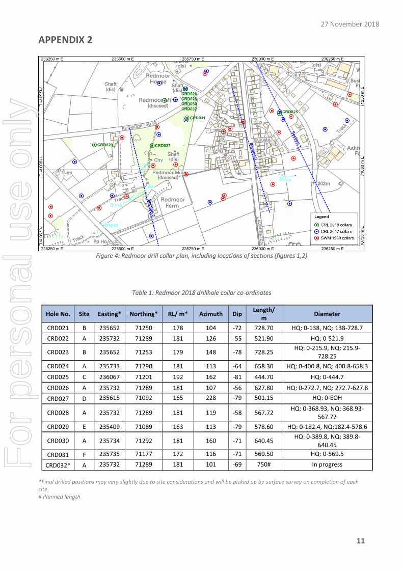
CRD031 F 235735 71177 172 116 -71 569.50 HQ: 0-569.5
CRD032* A 235732 71289 181 101 -69 750# In progress
*Final drilled positions may vary slightly due to site considerations and will be picked up by surface survey on completion of each site # Planned length
For
per
sona
l use
onl
y
27 November 2018
12
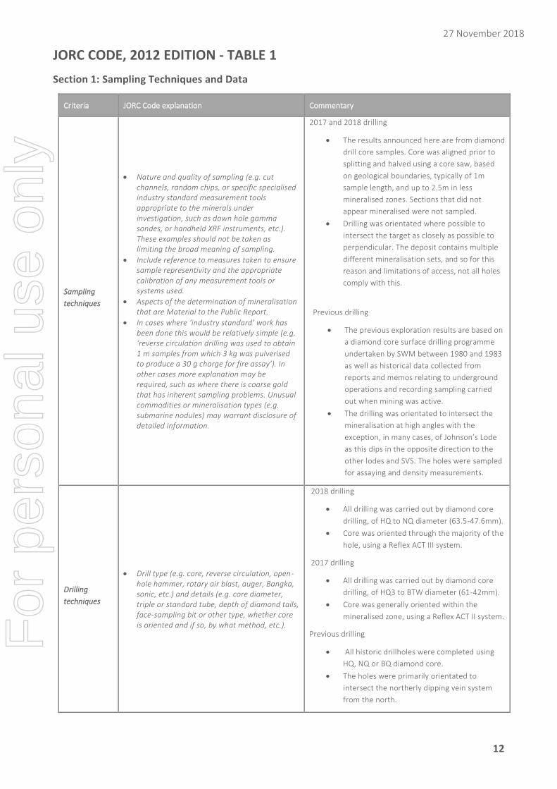
JORC CODE, 2012 EDITION - TABLE 1
Section 1: Sampling Techniques and Data
Criteria JORC Code explanation Commentary
Sampling
techniques
• Nature and quality of sampling (e.g. cut channels, random chips, or specific specialised industry standard measurement tools appropriate to the minerals under investigation, such as down hole gamma sondes, or handheld XRF instruments, etc.). These examples should not be taken as limiting the broad meaning of sampling.
• Include reference to measures taken to ensure sample representivity and the appropriate calibration of any measurement tools or systems used.
• Aspects of the determination of mineralisation that are Material to the Public Report.
• In cases where ‘industry standard’ work has been done this would be relatively simple (e.g. ‘reverse circulation drilling was used to obtain 1 m samples from which 3 kg was pulverised to produce a 30 g charge for fire assay’). In other cases more explanation may be required, such as where there is coarse gold that has inherent sampling problems. Unusual commodities or mineralisation types (e.g. submarine nodules) may warrant disclosure of detailed information.
2017 and 2018 drilling
• The results announced here are from diamond
drill core samples. Core was aligned prior to
splitting and halved using a core saw, based
on geological boundaries, typically of 1m
sample length, and up to 2.5m in less
mineralised zones. Sections that did not
appear mineralised were not sampled.
• Drilling was orientated where possible to
intersect the target as closely as possible to
perpendicular. The deposit contains multiple
different mineralisation sets, and so for this
reason and limitations of access, not all holes
comply with this.
Previous drilling
• The previous exploration results are based on
a diamond core surface drilling programme
undertaken by SWM between 1980 and 1983
as well as historical data collected from
reports and memos relating to underground
operations and recording sampling carried
out when mining was active.
• The drilling was orientated to intersect the
mineralisation at high angles with the
exception, in many cases, of Johnson’s Lode
as this dips in the opposite direction to the
other lodes and SVS. The holes were sampled
for assaying and density measurements.
Drilling
techniques
• Drill type (e.g. core, reverse circulation, open-hole hammer, rotary air blast, auger, Bangka, sonic, etc.) and details (e.g. core diameter, triple or standard tube, depth of diamond tails, face-sampling bit or other type, whether core is oriented and if so, by what method, etc.).
2018 drilling
• All drilling was carried out by diamond core
drilling, of HQ to NQ diameter (63.5-47.6mm).
• Core was oriented through the majority of the
hole, using a Reflex ACT III system.
2017 drilling
• All drilling was carried out by diamond core
drilling, of HQ3 to BTW diameter (61-42mm).
• Core was generally oriented within the
mineralised zone, using a Reflex ACT II system.
Previous drilling
• All historic drillholes were completed using
HQ, NQ or BQ diamond core.
• The holes were primarily orientated to
intersect the northerly dipping vein system
from the north.
For
per
sona
l use
onl
y
27 November 2018
13
Criteria JORC Code explanation Commentary
Drill sample
recovery
• Method of recording and assessing core and chip sample recoveries and results assessed.
• Measures taken to maximise sample recovery and ensure representative nature of the samples.
• Whether a relationship exists between sample recovery and grade and whether sample bias may have occurred due to preferential loss/gain of fine/coarse material.
2018 drilling
• Recoveries were generally good through
mineralisation, and typically more than 90%.
Recoveries were measured for each run
drilled, normally within 24 hours of the hole
being drilled.
• Voids where encountered were clearly logged
as such.
• Other than where an area may have been
mined, as mentioned above, no negative
relationship was seen between recovery and
mineralisation.
2017 drilling
• Recoveries were generally good through
mineralisation, and typically more than 90%.
Recoveries were measured for each run
drilled, normally within 24 hours of the hole
being drilled.
• Triple Tube drilling was used where possible
given available equipment and core diameter,
to enable precise definition of recovery.
• Voids where encountered were clearly logged
as such.
• Other than where an area may have been
mined, as mentioned above, no negative
relationship was seen between recovery and
grade.
Previous drilling
• All historic drillholes were completed using
HQ, NQ or BQ diamond core. Core recovery
was recorded on the logs and the results
suggest that the core recovery was relatively
high, typically ranging from 80% to 100%, the
higher losses being in areas of poor ground.
Geologica and CRL are not aware of specific
measures taken to reduce core loss but where
excessive losses were experienced holes were
re-drilled. There is no apparent relationship
between core loss and grade.
Logging
• Whether core and chip samples have been geologically and geotechnically logged to a level of detail to support appropriate Mineral Resource estimation, mining studies and metallurgical studies.
• Whether logging is qualitative or quantitative in nature. Core (or costean, channel, etc.) photography.
• The total length and percentage of the relevant intersections logged.
2017 and 2018 drilling
• All drill core was digitally logged for lithology,
veining, mineralisation, weathering,
geotechnical characteristics, and structure.
• All core was photographed and referenced to
downhole geology using Micromine software.
• Voids where encountered were clearly logged
as such.
Previous drilling
• Detailed geological core logging and recording
of the features of the core was undertaken as
part of the historic drilling campaign and
these logs remain available for review.
For
per
sona
l use
onl
y
27 November 2018
14
Criteria JORC Code explanation Commentary
• Mineralogical descriptions are qualitative but
detailed. Details of all relevant intersections
are separately noted.
Sub-sampling
techniques
and sample
preparation
• If core, whether cut or sawn and whether quarter, half or all core taken.
• If non-core, whether riffled, tube sampled, rotary split, etc. and whether sampled wet or dry.
• For all sample types, the nature, quality and appropriateness of the sample preparation technique.
• Quality control procedures adopted for all sub-sampling stages to maximise representivity of samples.
• Measures taken to ensure that the sampling is representative of the in situ material collected, including for instance results for field duplicate/second-half sampling.
• Whether sample sizes are appropriate to the grain size of the material being sampled.
2017 and 2018 drilling
• Sawn half core was used for all samples
submitted to the laboratory. The remaining
half core is preserved in the core trays as a
record.
• The routine sample procedure is always to
take the half core to the left of the orientation
line looking down the hole.
• The halved samples were submitted to ALS
Loughrea laboratory. There, samples, typically
in the range 3-7kg were dried and finely
crushed to better than 70 % passing a 2 mm
screen. A split of up to 250 g was taken and
pulverized to better than 85 % passing a 75
micron screen.
• Copies of internal laboratory QC validating
that the targeted particle size was being
achieved were received.
• 5% of samples were re-assayed as coarse
reject duplicates.
• Once assay results are received, the results
from duplicate samples are compared with
the corresponding routine sample to ascertain
whether the sampling is representative.
• Sample sizes are considered appropriate for
the style and type of mineralisation, if halved
core is used.
Previous drilling
• Historic drill core was typically sampled at 2 m
intervals, using either half core (‘split core’)
analysis or geochemical chip sampling. The
remaining half core (relating to split core
analysis) was stored for reference. No details
are available with regards quality control
procedures in general.
Quality of
assay data
and
laboratory
tests
• The nature, quality and appropriateness of the assaying and laboratory procedures used and whether the technique is considered partial or total.
• For geophysical tools, spectrometers, handheld XRF instruments, etc., the parameters used in determining the analysis including instrument make and model, reading times, calibrations factors applied and their derivation, etc.
• Nature of quality control procedures adopted (e.g. standards, blanks, duplicates, external laboratory checks) and whether acceptable levels of accuracy (i.e. lack of bias) and precision have been established.
2017 and 2018 drilling
• Analysis by method ME-ICP81x was carried
out using a sodium peroxide fusion for
decomposition and then analysed by ICP-AES
for 34 elements, including Sn, Cu, and W. The
upper and lower detection limits are
considered acceptable for the target elements
of Sn, Cu, and W. A limited number of samples
were also analysed for silver by method Ag-
ICP61.
• The laboratory shared their internal QC data
on blanks, pulp duplicates and standards. CRL
also inserted 5% each of blanks, standards and
duplicates, as a further control.
• While there was some spread in the
repeatability of the 2017 coarse rejects, CRL’s
For
per
sona
l use
onl
y
27 November 2018
15
Criteria JORC Code explanation Commentary
blanks show no significant contamination
issues and the assays of the laboratory
standards, which cover a range of metal
values for each of Sn, Cu, W, show no bias.
Previous drilling
• Historic drill core was typically sampled at 2 m
intervals, using either half core (‘split core’)
analysis or geochemical chip sampling. The
remaining half core (relating to split core
analysis) was stored for reference. No details
are available with regards quality control
procedures in general.
• No information is available on the laboratory
sample preparation and analysis and quality
control programmes used for the historic
drilling.
• Verification sampling was previously
completed by SRK* and CRL, under which
samples were prepared at SGS Cornwall and
assayed at the Wheal Jane laboratory. SRK
visited these facilities and reviewed the
sample preparation and assaying process. The
assaying process involves crushing, splitting,
milling and homogenization. XRF and Atomic
Absorption Spectroscopy (AAS) was
conducted on the samples. SRK considered
the laboratory to be working in accordance
with accepted industry standards.
Verification of
sampling and
assaying
• The verification of significant intersections by either independent or alternative company personnel.
• The use of twinned holes.
• Documentation of primary data, data entry procedures, data verification, data storage (physical and electronic) protocols.
• Discuss any adjustment to assay data.
2018 drilling
• Geologica UK has reviewed the assay results
included in this release.
2017 drilling
• SRK received copies of CRL’s database and
laboratory analysis certificates and reviewed
the significant intersections.
• No twinned holes have been drilled as part of
the current programme.
• SRK visited the CRL site and audited data entry
and verification procedures. Data is
automatically backed up off-site.
• Within significant intercepts, values at
detection limits were replaced with 0.5 of the
detection limit value. Where duplicate assays
exist for the same interval a straight average
is taken.
Previous drilling
• SRK was supplied with scanned historical drill
logs which have been entered into a Microsoft
Excel database.
• SRK completed a number of checks on the raw
data and data entry process and applied
For
per
sona
l use
onl
y
27 November 2018
16
Criteria JORC Code explanation Commentary
corrections where necessary. Based on the
verification work completed, SRK is confident
that the compiled excel database is an
accurate reflection of the available historic
drilling data.
• Whilst further verification work is required to
add confidence to the database, SRK
considered that the check sampling
undertaken confirms the presence of
anomalous grades for the primary elements
assayed, and that the 2017 drilling confirms
these.
Location of
data points
• Accuracy and quality of surveys used to locate drill holes (collar and down-hole surveys), trenches, mine workings and other locations used in Mineral Resource estimation.
• Data spacing for reporting of Exploration Results.
• Whether the data spacing and distribution is sufficient to establish the degree of geological and grade continuity appropriate for the Mineral Resource and Ore Reserve estimation procedure(s) and classifications applied.
• Whether sample compositing has been applied.
2018 drilling
• The current programme aims to extend
previously identified mineralisation.
• Data spacing will depend on the eventual
extent of the 2018 program, but is anticipated
once complete to be 100-150m apart, and
often less.
2017 drilling
• The current programme aimed at extending
and improving continuity of previously
identified mineralisation.
• The data spacing varies depending on the
target, within the SVS this is 100-150m apart,
and often less.
• Compositing was applied in order to calculate
intersected width equivalents, on an interval
length weighted-average basis.
Previous drilling
• The drillholes and sample intersections are
typically some 100-150m apart in the main
lodes and lode systems of interest which has
provided a reasonable indication of continuity
of structure for the SVS, Johnson’s Lode and
the Great South Lode. All individual sample
assays remain available.
Orientation of
data in
relation to
geological
structure
• Whether the orientation of sampling achieves unbiased sampling of possible structures and the extent to which this is known, considering the deposit type.
• If the relationship between the drilling orientation and the orientation of key mineralised structures is considered to have introduced a sampling bias, this should be assessed and reported if material.
2018 drilling
• Drillholes in the programme target the SVS
and as secondary targets ancillary lodes
including Kelly Bray lode.
• In order to minimize impact on local residents,
some holes were drilled oblique to the
mineralisation.
• Notwithstanding this, the SVS mineralisation is
interpreted to be a broad tabular mineralised
zone. The orientation of the drilling is believed
to be appropriate for the evaluation of this
geometry as presently understood.
2017 drilling
• Drillholes in the programme targeted the SVS,
Johnson’s Lode, Great South Lode, and Kelly
Bray Lode, each of which have different dips.
• Some holes hit more than one of the above,
and therefore could not be perpendicular to
all mineralisation.
For
per
sona
l use
onl
y
27 November 2018
18
Criteria JORC Code explanation Commentary
• In order to minimize impact on local residents,
some holes were drilled oblique to the
mineralisation.
• Notwithstanding this, the SVS mineralisation is
interpreted to be a broad tabular mineralised
zone with an internal plunge component. The
orientation of the drilling is believed to be
appropriate for the evaluation of this
geometry as presently understood. It is
recommended that this be further assessed
during subsequent drilling.
• Intercepts are reported as apparent
thicknesses except where otherwise stated.
The data spacing varies depending on the
target, within the SVS this is 100-150m apart,
and often less.
Previous drilling
• The drillholes and sample intersections are
typically some 100-150m apart in the main
lodes and lode systems of interest which has
provided a reasonable indication of continuity
of structure for the SVS, Johnson’s Lode and
the Great South Lode. All individual sample
assays, and some of the drill core, remain
available.
• The drillholes were orientated to intersect the
SVS and Great South Lode at intersection
angles of between 45 and 90 degrees. Two or
three holes were though often drilled from
one site to limit the number of drill sites
needed and also the intersection angles with
Johnson’s Lode are shallower then ideal due
to the different orientation of this structure.
Full intersections are however available in all
cases so there should be no material bias and
the differences between intersected and true
lode widths has been accounted for in SRK’s
evaluation procedures.
Sample
security • The measures taken to ensure sample security.
2017 and 2018 drilling
• All core is stored at CRL’s secure warehouse
facility and halved core retained.
• Samples are catalogued, ticketed, weighed,
securely palletized, and dispatched by courier
to the laboratory, where sample receipt is
confirmed by email.
• ALS is an internationally accredited laboratory.
Previous drilling
• No information is available on sample security
for the historic drilling.
• The majority of the core boxes which had
been stored in a dry container on racks
remain intact though some of the core has
been mixed up and core markers displaced
over time and these had to be re-arranged
appropriately.
For
per
sona
l use
onl
y
27 November 2018
19
Criteria JORC Code explanation Commentary
• SRK is satisfied that the verification re-
sampling programmes undertaken by SRK and
CRL utilised industry best practices for Chain
of Custody procedures.
Audits or
reviews • The results of any audits or reviews of
sampling techniques and data.
2018 drilling
• Geologica visited CRL’s operations and facility
in August 2018 and conducted an audit of
logging and sampling procedures. No
significant concerns were identified.
• Geologica are based in Cornwall and are
verifying sampling through the 2018 drilling
program on an ongoing basis.
2017 drilling
• SRK visited CRL’s operations and facility in
June 2017 and conducted an audit of logging
and sampling procedures. No significant
concerns were identified.
Previous drilling
• SRK is unaware of any reviews or audits which
may have been completed other than those
undertaken by SRK itself.
Section 2: Reporting of Exploration Results
Criteria JORC Code explanation Commentary
Mineral
tenement and
land tenure
status
• Type, reference name/number, location and ownership including agreements or material issues with third parties such as joint ventures, partnerships, overriding royalties, native title interests, historical sites, wilderness or national park and environmental settings.
• The security of the tenure held at the time of reporting along with any known impediments to obtaining a licence to operate in the area.
The Project is located immediately south of the village
of Kelly Bray and approximately 0.5km north of the
town of Callington in Cornwall in the United Kingdom.
In October 2012, NAE Resources (UK) Limited, acquired
a 100% interest in the Redmoor Tin-Tungsten Project
through an Exploration License and Option Agreement
with the owner of mineral rights covering a large area
of approximately 23km2 that includes the Redmoor
Project. The Exploration License was granted for an
initial period of 15 years with modest annual payments.
On 14 November 2016, NAE Resources (UK) Limited
changed its name to Cornwall Resources Limited (CRL).
CRL also has the option to a 25 year Mining Lease,
extendable by a further 25 years which can be exercised
at any time during the term of the Exploration License.
The Mining Lease permits commercial extraction of the
minerals subject to obtaining planning and other
approvals required and is subject to a 3% Net Smelter
Return royalty payable to the mineral right owner once
commercial production has commenced. CRL also has a
pre-emptive right over the sale of the mineral rights by
the vendor. Surface land access for exploration drilling
and mining over some of the Redmoor deposit is also
included in these agreements.
For
per
sona
l use
onl
y
27 November 2018
20
Criteria JORC Code explanation Commentary
Exploration
done by other
parties
• Acknowledgment and appraisal of exploration by other parties.
South West Minerals (SWM) conducted exploration,
including drilling, in the area from 1980 to 1986. The
area was the subject of underground development and
processing from the 18th century to around 1946.
Geologica are unaware of any exploration undertaken
by parties other than South West Minerals (SWM).
Geology • Deposit type, geological setting and style of mineralisation.
The geology of the Redmoor Project is typical of other
established mining areas of Cornwall. Tin, tungsten
and metal sulphide mineralisation is spatially related to
granite intrusions which have caused mineral
containing fluids to transport and deposit tin, tungsten
and copper bearing minerals along fractures and faults
in surrounding rocks.
At Redmoor the mineralisation occurs both in discrete
veins (lodes) and within a stockwork and sheeted zone
of numerous closely spaced quartz veins known as the
Sheeted Vein System (SVS).
Drill hole
Information
• A summary of all information material to the understanding of the exploration results including a tabulation of the following information for all Material drill holes: o easting and northing of the drill hole collar o elevation or RL (Reduced Level – elevation
above sea level in metres) of the drill hole collar
o dip and azimuth of the hole o down hole length and interception depth o hole length.
• If the exclusion of this information is justified on the basis that the information is not Material and this exclusion does not detract from the understanding of the report, the Competent Person should clearly explain why this is the case.
2018 drilling
• Drillhole collar data including position, RL,
azimuth, inclination, and length is provided in
Table 1.
2017 drilling
• Drillhole collar data including position, RL,
azimuth, inclination, and length were
reported in the releases dated 7 September, 1
November, and 11 December 2018.
• Depths of intercepts were reported in the
releases dated 7 September, 1 November, and
11 December 2018.
• Figures previously presented in the 26
November 2015 announcement show the
relative location and orientation of the drilling
completed by SWM.
Data
aggregation
methods
• In reporting Exploration Results, weighting averaging techniques, maximum and/or minimum grade truncations (e.g. cutting of high grades) and cut-off grades are usually Material and should be stated.
• Where aggregate intercepts incorporate short lengths of high grade results and longer lengths of low grade results, the procedure used for such aggregation should be stated and some typical examples of such aggregations should be shown in detail.
• The assumptions used for any reporting of metal equivalent values should be clearly stated.
2017 and 2018 drilling
• Weighted average intercepts were calculated
using sample weighting by length of sample
interval.
• No high cut was thought to be appropriate.
• Intervals were constructed to reflect average
mineralisation of more than 0.5% Sn
equivalent. Internal dilution is accepted where
a geological basis is thought to exist for
reporting a wider package, for example within
the SVS.
Previous drilling
• These are geologically rather than cut-off
defined and all composited grades reported
are length weighted assays without cutting.
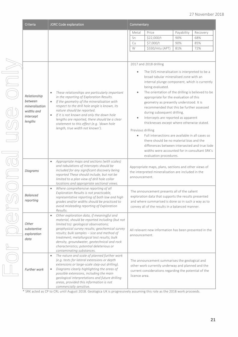
For each of 2017 and previous drilling, results are
expressed in Sn equivalent values. The assumptions for
this calculation are:
For
per
sona
l use
onl
y
27 November 2018
21
Criteria JORC Code explanation Commentary
Metal Price Payability Recovery
Sn $22,000/t 90% 68%
Cu $7,000/t 90% 85%
W $330/mtu (APT) 81% 72%
Relationship
between
mineralisation
widths and
intercept
lengths
• These relationships are particularly important in the reporting of Exploration Results.
• If the geometry of the mineralisation with respect to the drill hole angle is known, its nature should be reported.
• If it is not known and only the down hole lengths are reported, there should be a clear statement to this effect (e.g. ‘down hole length, true width not known’).
2017 and 2018 drilling
• The SVS mineralisation is interpreted to be a
broad tabular mineralised zone with an
internal plunge component, which is currently
being evaluated.
• The orientation of the drilling is believed to be
appropriate for the evaluation of this
geometry as presently understood. It is
recommended that this be further assessed
during subsequent drilling.
• Intercepts are reported as apparent
thicknesses except where otherwise stated.
Previous drilling
• Full intersections are available in all cases so
there should be no material bias and the
differences between intersected and true lode
widths were accounted for in consultant SRK’s
evaluation procedures.
Diagrams
• Appropriate maps and sections (with scales) and tabulations of intercepts should be included for any significant discovery being reported These should include, but not be limited to a plan view of drill hole collar locations and appropriate sectional views.
Appropriate maps, plans, sections and other views of
the interpreted mineralisation are included in the
announcement.
Balanced
reporting
• Where comprehensive reporting of all Exploration Results is not practicable, representative reporting of both low and high grades and/or widths should be practiced to avoid misleading reporting of Exploration Results.
The announcement presents all of the salient
exploration data that supports the results presented
and where summarised is done so in such a way as to
convey all of the results in a balanced manner.
Other
substantive
exploration
data
• Other exploration data, if meaningful and material, should be reported including (but not limited to): geological observations; geophysical survey results; geochemical survey results; bulk samples – size and method of treatment; metallurgical test results; bulk density, groundwater, geotechnical and rock characteristics; potential deleterious or contaminating substances.
All relevant new information has been presented in the
announcement.
Further work
• The nature and scale of planned further work (e.g. tests for lateral extensions or depth extensions or large-scale step-out drilling).
• Diagrams clearly highlighting the areas of possible extensions, including the main geological interpretations and future drilling areas, provided this information is not commercially sensitive.
The announcement summarises the geological and
other work currently underway and planned and the
current considerations regarding the potential of the
licence area.
* SRK acted as CP to CRL until August 2018. Geologica UK is progressively assuming this role as the 2018 work proceeds.