Page 1
Signal & Image Processing : An International Journal (SIPIJ) Vol.3, No.2, April 2012
DOI : 10.5121/sipij.2012.3201 1
Spectrogram Enhancement By Edge Detection Approach Applied To Bioacoustics Calls
Classification
W.B. Hussein*, M.A. Hussein and T. Becker
Group of (Bio-) Process Technology and Process Analysis, Faculty of Life Science
Engineering, Technische Universität München, Germany [email protected]
ABSTRACT
Accurate recognition of sound patterns in spectrograms is important step for further recognition
applications. However, background noise forms fundamental problem regardless the species under study.
In this paper, crest factor feature was extracted from the limited dynamic range spectrogram. The
developed crest factor image behaved as smoothed version of the spectrogram, at which edges of the
involved sound patterns were detected without the need of prior smoothing filters and their scaling
constraints. Attached noise – surrounds the detected edges – was removed, to form the enhanced
spectrogram. The method was compared to other enhancement approaches such like spectral Subtraction
and wavelet packet decomposition. Comparison was performed on different structure patterns of bats and
birds. Results indicate how the method is promising for efficiently enhancing the spectrogram while
preserving its temporal and spectral accuracy. The method correctly classified three bioacoustics species
with an accuracy of 94.59%, using few 2D features of their enhanced spectrograms
.
Keywords
Spectrogram Enhancement, Edge Detection, Bioacoustics Classification, Pattern Recognition.
1. Introduction
1.1. Problem formulation
Bioacoustics calls have been efficiently employed for a long time for species detection,
classification, and recognition. These calls handle the sound patterns which are almost unique and
oriented for the investigated bio-source. Several temporal and spectral sound features are
extracted from these patterns in time and frequency domains; respectively. These features are
used to train and develop a learning system, using methods such as Artificial Neural Network,
which afterwards is able to successfully recognize the test bioacoustics calls to their
corresponding groups or species, according to their features values. The approach have been
widely used in many life science problems, such as the bioacoustics detection of hidden grain
weevils for early treatment [1], and detection of bat ultrasound echolocation calls in the windmills
region to avoid their expected collision with the blades[2].
In general, collection of time domain and frequency domain features are used to develop more
accurate detection system, revealing the importance of having a reliable spectrogram (time-
frequency intensity 2D image) of the specified sound.Spectrogram is an important representation
of sound data looks like the human hearing which is based on a kind of real-time spectrogram
Page 2
Signal & Image Processing : An International Journal (SIPIJ) Vol.3, No.2, April 2012
2
encoded by the cochlea of the inner ear [3], to classify and recognize patterns of sound samples.
However, spectrogram is usually attached by different forms of noise; including those formed
during sound recording[4],and those produced during the transformation to frequency domain
result in spectral leakage, and up to 10% error(s) infrequency and/or power spectrum
computations [5]. These noises directly degrade the quality of the waveform, deteriorate the
worth of the extracted features and thus lead to inaccuracy in recognition of the sound patterns
[6].Further difficulty is added to the problem due to variability of patterns structure, which can
vary greatly including vertical straight, sloped straight, sinusoidal type and relatively random
patterns. However, filtering noisy signals through the spectrogram is considered more effective
than separate filtrations in time and/or frequency domain, since sound patterns do not cover the
whole spectrogram image, and therefore easier to filter off the noise.
A spectrogram enhancement approach which is independent on the noise type, level, and structure
is required. Once established, the pattern recognition algorithms can operate efficiently and
smoothly on the clear “only patterns” spectrogram. Therefore, the problem of spectrogram
enhancement and accurate detection of the sound patterns has attracted researchers’ interest from
a variety of backgrounds ranging among signal and image processing, and statistical models [7,8].
1.2. Related work
Common and recent techniques for spectrogram enhancement include basic band pass
filtering[9], spectral subtraction[10], Wiener filter[11], and wavelet packet decomposition[12,
13].Simple methods, such as the band pass filtering, originally employed the use of time-domain
filtering of the corrupted signal, however, this is only successful when removing low or high
frequency noise and does not provide satisfactory results for many species which have frequency
range overlaps with their attached noises [14].
Although the base spectral subtraction method is very simple and efficient, it assumes the noise to
be additive and uncorrelated with the signal [15]. Moreover, the enhancement by spectral
subtraction tends to produce sounds with musical artifacts that are often more objectionable than
the original noise [16]. Later, the multi-band spectral subtraction method was proposed, at which
the corrupted sound is initially divided into several frequency bands, and then the spectral
subtraction method is applied to each band[17]. This method outperforms the standard power
spectral subtraction method resulting in superior spectrogram quality and largely reduced musical
noise. Meanwhile, the Wiener filter technique basically considers the beginning of a signal is
noise, and its adaptive type removes noise based on a training data [18]. However, during the
operation on data with unknown noise, the noise level can be underestimated and the
enhancement can be slightly milder [19]. The methods based on wavelet packet decomposition
are effective in removing background noise in the spectrogram. But they cannot suppress much of
the noise generated during the Fourier transformation, because the former noise is usually random
Gaussian distribution while the latter may be modeled by Rayleigh distribution [7,20].
Image analysis techniques applied to this area treat the spectrogram as an image, provides a wide
range of methods which could be beneficial to this problem. One of these developed methods is
the noise suppression using spectrogram morphological filtering [21,22], applying two
subsequent operations of erosion and dilation. The erosion was responsible to remove noise from
the noisy spectrogram while dilation used to restore any erroneously removed sound patterns.
However, it improves the enhancement accuracy by only 10% when combined by nonlinear
spectral subtraction with a suitable selection of the threshold. The author in [23] proposed an edge
detection method which initially smoothes the spectrogram using a Gaussian filter, followed by
thresholding each point by comparison to the background measurement. This allows for time
invariant noise conditions and computing independently for each frequency bin, which
successfully detected (90%) of whale calls. If the smoothing kernel is quite large, the detrimental
effect is reduction in the detection accuracy, especially at low SNR. Meanwhile, the authors in
[24] passed the spectrogram through 2D bilateral filter to reduce noise and preserve its patterns
Page 3
Signal & Image Processing : An International Journal (SIPIJ) Vol.3, No.2, April 2012
3
edges. The filtered spectrogram is sent to two parallel processing paths, at which the first path
extracts significant patterns from background noise. The second path performs the edge detection
and restructures the rough patterns that can be used as a mask. The processed image from the first
path passes through a mask generated from the second path. However, pattern recognition still
severely depends on image processing skills and spectrogram resolutions which lead to
concealment of very short patterns. Apartial differential equation technique was used in [25] for
edge enhancement and noise reduction based on a regularization of the mean curvature motion
equation. However, the comparisons indicate that the method gives almost similar results as the
wavelet based methods.
In this paper, an improved spectrogram enhancement method has been developed based on the
last advances in the edge detection techniques. The dynamic power range of the spectrogram is
limited to avoid the problem of low level portions of the spectrogram expanding and thereby
obscuring the detail of the energetic portions. Afterwards, the crest factor image is calculated as a
smoothed version of the original spectrogram image, hence escaping the application of smoothing
Gaussian filters and their drawbacks [26].Based on the edge detection algorithm presented in
[28], the sound patterns in the crest factor image are detected. Afterwards, the original power
values of the patterns edges and their interior are reconstructed, while the power values of the
patterns surrounding are eliminated, as they represent the attached noises whether attached to the
sound or generated during the frequency domain transformation. The proposed method was
applied to several bioacoustics calls of different SNR values, and compared to the results given
by band pass, multi-band spectral subtraction, Wienerfilter, and wavelet packet decomposition
methods, with respect to subjective and objective measures. Finally, possible implementations of
the proposed method in obtaining the enhanced frequency and power contours, reconstruction of
the enhanced waveform, and simplified pattern recognition operation are presented.
2. Material and method
2.1.Signal processing
Audio sound streams are sampled in time domain with suitable sampling frequencies, selected to
be higher than the double of maximum frequency in the sound stream, satisfying the Nyquist
sampling theorem [5] and avoid antialiasing in the signal reconstruction. Figure (1) shows an
example for the call of Sitta canadensis bird which was sampled at 11025 Hz. The signal is
divided into segments with length of 1% of the total signal length and 90% overlapping
percentage. Each segment is then multiplied by Bartlett window function and transformed to
frequency domain through Fast Fourier Transform (FFT). The frequency domain representation
of the signal (i.e., spectrogram) is the power spectrum distribution with frequency, at each time
instant, as plotted in figure (2).The implementation of the Bartlett window function is to have
better frequency resolution while keeping acceptable spectral leakage and amplitude accuracy
[27].
The resultant spectrogram contains important sound patterns of the signal immersed in attached
noise. These noises are not only due to the base noise attached to the sound, but also generated
during FFT, therefore, cleaning the signal in time domain, will not ensure clean spectrogram.
Page 4
Signal & Image Processing : An International Journal (SIPIJ) Vol.3, No.2, April 2012
4
Figure 1. A sound stream for Sitta canadensis bird in time domain revealing its contents of
two long pulses and one long inter-interval.
Figure 2. The spectrogram for the time domain signal of figure (1), after being divided into
segments of length equal to 1% of the total signal length, multiplied by Bartlett window
function and transformed to frequency domain using FFT.
2.2.Limiting the dynamic range
The attached noise to the spectrogram may be assumed to have almost same power value, which
can be removed from the whole spectrogram. However, this will eliminate as well the non-noisy
patterns which have this power value.Therefore, this thresholding scheme should be carefully
applied through the physical fact of the limited dynamic range. Althoughthe whisper cannot be
heard in loud surroundings, the spectrogram will contain all details about whisper and loud sound
powers. Thus, the spectrogram powers have to be limited, to avoid much of the attached whisper
(i.e., noise).The range is limited to 40 dB below the maximum value for all tested sounds, because
most bioacoustics signals are expanded/slowed to the human speech range, which is normally
perceived over this range [29]. Therefore, any point with power value outside this range,
including those of noise as well as very weak patterns, are eliminated from the spectrogram, as
shown in figure (3).
Page 5
Signal & Image Processing : An International Journal (SIPIJ) Vol.3, No.2, April 2012
5
Figure 3. The limited spectrogram after the power values were limited to a dynamic range of
40 dB, clarifying how most of the noise and very weak sound patterns were eliminated.
2.3.Detection of the pattern edges
The algorithm starts by sliding a 5*5 matrix (mask) over the limited dynamic range spectrogram
image in x direction and then in y direction, with step of one pixel. The represented pixel of the
mask is its centroid which is calculated by equation (1). The intensities of the pixels (i.e., power
values) enclosed by the mask are used to calculate the crest factor feature, given in equation (2),
which is a ratio of the maximum value to the root mean square value, indicating how much
impacting is occurring inside the mask, as schematically explained in figure (4). ���� ����� = ∑ � ∗ ������ \ ∑ ������ (1) � = ��������� (2)
Where fi is the gray level intensity value of pixel i, and the back slash means that only the
quotient of the division is considered. ����� and ���� are the peak and root mean square of the
pixels intensities; respectively, and C is the crest factor of the mask.
Figure 4. The crest factor for some basic curves, showing how much impacting occurs.
As a result, the crest factor image is obtained, by gathering the local crest factors calculated
during the sliding of the mask. Although this edge detection algorithm follows the one presented
in [28], it is applied to the crest factor image instead of combination of energy and skewness
images, because this combination presents both strong edges (output of the energy feature) and
weak edges (output of the skewness feature). Hence, the noises are also detected as patterns,
displayed in figure (5a)with a signal to noise ratio (SNR) - given in equation (3) - of1.95.
Alternatively, the crest factor feature of an image presents the edges that have impact to their
Page 6
Signal & Image Processing : An International Journal (SIPIJ) Vol.3, No.2, April 2012
6
surrounding (i.e., non-weak edges), as displayed in figure (5b) with SNR of2.82. Furthermore, the
limited dynamic range makes the crest factor more meaningful since it is a measure of relative
spatial intensity change.
"#$ = 10'�(�) ∑ *+,���∑-*+,��� − */01�01- (3)
Where Pclean and Poutput are the clean and output power values; respectively.
(a)
(b)
Figure5. Two features from the limited dynamic range spectrogram of figure (3), (a) combination
of energy and skewness images, following the algorithm presented in [28], and (b) the crest
factor image.
Afterwards, the Sobel operators given in equation (4) are employed on the crest factor image,
through equation (5),to get its gradient images (CxandCy). And with the aid of equations (6) and
(7), the edges strength (E) and the edges directions (3) are calculated; respectively.
∆5= 6−1 0 1−2 0 2−1 0 17 , ∆9= 6 1 2 10 0 0−1 −2 −17 (4) �5 = ∆5 ∗ �, �9 = ∆9 ∗ � (5) < = =�5> + �9>(6)
3 = ��A� B�9�5C + D2 (7)
Where∆5and∆9are the derivative operators in x and y directions; respectively. �5 and �9 are the
intensities of the gradient images in x and y direction; respectively. E is the edge strength and 3 is
the edge direction with the x-axis.
Finally, the edges image is formed by the values of edges strength (E), and executed by the non-
maximum suppression algorithm and flux equilibrium check [28], to suppress thick edges to one
pixel width and fill the missing pixels in the edge direction. Consequently, the final edges image,
given in figure (6) is produced, which separates the patterns from surrounding noise. However,
the edges do not provide information about where exactly are the inner of the patterns and where
are their surroundings.
Page 7
Signal & Image Processing : An International Journal (SIPIJ) Vol.3, No.2, April 2012
7
Figure 6. The edges image of the limited dynamic range spectrogram using 5*5 mask and a
flux check matrix of size 3*3
2.4. Reconstructing the spectrogram
A classification condition is applied to each row and afterwards each column of the edges image.
This condition compares the average power spectrum of all pixels among two subsequent edges
in one row (column), with respect to the average power spectrum of these two edges, as clarified
in the algorithm given in figure (7).
Figure 7. Schematic diagram and algorithm for the classification condition which classifies sound
patterns from their surrounding noise.
Thus, the patterns are defined and their power values are restored, and the surrounding noises are
also defined and their power values are eliminated, results in the enhanced spectrogram shown in
figure (8).
Figure 8. The enhanced spectrogram by the proposed method revealing sound patterns and
eliminating their surrounding noise.
Page 8
Signal & Image Processing : An International Journal (SIPIJ) Vol.3, No.2, April 2012
8
3. Experimental results and discussion
The results obtained by the proposed method [PM] were investigated and compared to those
obtained by conventional and modern spectrogram enhancement methods. The designing
parameters of these methods were carefully selected to give best enhanced spectrogram for the
first application (Rhinolophus blasii bat), and were fixed over the following applications to have
leading results and trustful comparisons. The first method is the widely used band pass filter [BP]
with a band width enclosing the sound patterns, and measured at half-power points (i.e., gain -3
dB relative to peak). The second method is multi-band spectral subtraction [MBSS]using 4
linearly-spaced frequency bands, over subtraction factor of 4 and power factor of 1.5 [7]. The
third method employs the Wiener filter [WF]with a spectral distance threshold of 3 and the initial
0.03 seconds considered as noise[11]. The fourth method is wavelet packet decomposition [WPD]
with soft thresholding and 5 level decompositions using symlet 8 wavelet [14, 16]. The number of
tested sound samples are 42 (each with 23-25 sec for Rhinolophus blasii bat), 37 (each with 23-25
sec for Barbastella barbastellus bat), 48 (each with 0.55-0.9 sec for Vanellus vanellus bird), and
45 (each with 0.55-0.9 sec for Parus major bird), with a frame length of0.025 sec multiplied by
Bartlett window function, and 90% overlapping percentage.
The analysis was applied by both subjective and objective measures of enhancement accuracy.
The subjective measure is borrowed from the field of psychology and the human judgment of
evaluation. One of the commonly used subjective measures is the Mean Opinion Score
(MOS),which gives a numerical estimation of the perceived quality of the media received [30].
After enhancing the spectrogram, its time domain signal was reconstructed and played back to 10
listeners. These listeners (5 females, and 5 males) were asked to give a score [1 = bad, 2 = poor, 3
= fair, 4 = good, and 5 = excellent] to estimate the enhanced spectrogram quality. Afterwards, the
MOS was calculated by averaging the given scores, and its confidence interval (CI) was
computed for 95% confidence level, as described in figure (9).
Figure 9. Normal distribution curve with 95% confidence level. A2 = P (z > z*) = (1 - 0.95) / 2
= 0.025, P (z <= z*) = 1 - 0.025 = 0.975, results in z* = 1.96 (from normal distribution table).
The confidence interval is(MOS − I1.96 ∗ σM, MOS + I1.96 ∗ σM). WhereI−N∗, N∗M encloses CI
on the standard deviation axis (z) and O is the standard deviation of the opinion score.
On the other hand, objective measures are borrowed from digital signal processing and
information theory, providing equations that can be used to measure the enhancement accuracy of
the enhanced spectrogram in comparison to the clean one. Four widely used and easy to
implement objective measures were employed, having high correlation with diagnostic
acceptability [11,30,31]. These measures are the overall Signal to Noise Ratio (SNR), Segmental
Signal to Noise Ratio (SSNR), Log Spectral Distance (LSD), and Itakura Saito (IS), given by
equations (3, 8, 9, and 10; respectively).SSNR is defined as the average of SNR values over
segments with sound activity, LSD is the spectral distance or distortion measure, expressed in dB,
between the enhanced and clean spectrograms, while IS a measure of the perceptual difference
between these two spectrograms. Furthermore, the average eccentricity (AE) was calculated by
equation (11), to simply check if the shape of sound patterns in the enhanced spectrogram was
changed from those in the original spectrogram, results in indication of whether the enhanced
spectrogram is augmented for further pattern recognition task. Eccentricity is the aspect ratio of
length to width of the minimum rectangle bounding the sound pattern.
Page 9
Signal & Image Processing : An International Journal (SIPIJ) Vol.3, No.2, April 2012
9
""#$ = 10P Q '�(�) Q R ∑ *+,���∑-*+,��� − */01�01-ST�UTA�
��T�VA���) (8)
X"Y = Z 2[" Q \10'�(�) R *+,���*/01�01S]>^_/>) (9)
a" = 2[" Q \ *+,���*/01�01 − '�(�) *+,���*/01�01 − 1]^_/>) (10)
b< = 1c Q Xdedf
d�� (11)
Where FS is the sampling rate of the signal, Pclean and Poutput are the clean and enhanced power
spectrum respectively. M is the number of spectrogram segments (set to 20), N is the number of
samples on a segment. L and W are the length and width; respectively, for the minimum rectangle
bounding the sound pattern, and K is the number of sound patterns in the spectrogram.
The applications were selected to cover different spectrogram shapes, including those with
narrow band, wide band, constant frequency, frequency modulated, short pulses, and long pulses
patterns. The original bioacoustics calls in each application were corrupted by several white
Gaussian noises, as descriptively shown in the left part of figure (10) for a saw tooth wave, result
in several time domain SNRs (30, 20, 10, 5, and 1 dB), and in correspondence several
spectrogram SNRs as demonstrated in the right part of figure (10), with average values of (3.66,
2.89, 2, 1.73, 1.52 dB; respectively).For each application and for each SNR, the five enhancement
methods (BP, MBSS, WF, WPD, and PM) were applied, and the results were subjectively and
objectively compared. It is worthy to mention that the silent regions were being removed, because
they can considerably influence the output objective measures.
Page 10
Signal & Image Processing : An International Journal (SIPIJ) Vol.3, No.2, April 2012
10
Figure 10. (top) A description for how the addition of different white Gaussian noise changes
the structure and SNR of the time domain signal. (bottom) The corresponding changes in the
spectrogram SNR averaged for the five applications.
3.1. Bioacoustics call of Rhinolophus blasii bat
The echolocation call of the Rhinolophus blasii bat which was investigated in this section
includes medium duration strong sound pulses separated by short intervals. These pulses cover
short Frequency Modulated (FM) band around 5 KHz, roughly estimated as Constant Frequency
(CF) band, which were slowed down by a time expansion factor of 10 to be in the audible range,
as shown in figure (11a).BP approach was able to remove most of the added noise, by rejecting
the spectrogram values outside the small band surrounds the frequency of 5 KHz, as graphically
shown in figure (11b) and numerically in the second column(s) of Table 1. Instead, the MBSS
and WF approaches were not successful to remove reasonable amount of noise, especially for
input SNRs less than 20 dB. The spectrograms generated with MBSS approach tended to
temporally spread out the sound pulses, while those generated by WF approach tended to
temporally cut from the duration of the pulses, as displayed in figure (11c, 11d) and the third and
fourth column(s) of Table 1; respectively.
Figure 11. (a) One of Rhinolophus Blasii bat echolocation calls at SNR = 1 dB (with expansion
factor of 10), and its enhanced spectrogram by (b) BP, (c) MBSS, (d) WF, (e) WPD, and (f)
PM.
Page 11
Signal & Image Processing : An International Journal (SIPIJ) Vol.3, No.2, April 2012
11
For higher values of input SNRs, the WF presented better enhancement. The WPD approach
removed reasonable amount of noise and presented good estimation for the time domain
resolution of the sound pulses. However, the five level decompositions produced repeated
patterns along the frequency axis, as shown in figure (11e) and the fifth column(s) of Table 1. The
PM dealt with the noisy spectrogram as an image, and was able to preserve the sound pulses
while removing most of the attached noise, as expressed in figure (11f) and the sixth column(s) of
Table 1.
Table 1. The subjective and objective measures for the spectrogram of Rhinolophus Blasii call
enhanced by BP, MBSS, WF, WPD, and PM
(A) MOS
input
SNR noisy BP MBSS WF WPD PM
1 1 (1,1) 2.8 (2.5,3) 1 (1,1) 1.1 (0.9,1.3) 1.7 (1.4,2) 1.6 (1.3,1.9)
5 1.1 (0.9,1.3) 2.9 (2.7,3.1) 1 (1,1) 1.2 (0.9,1.5) 1.8 (1.5,2) 2 (1.6, 2.4)
10 1.3 (1,1.6) 2.8 (2.5,3) 1.1 (0.9,1.3) 1.3 (1,1.6) 1.8 (1.4,2.2) 2.6 (2.3,2.9)
20 1.3 (0.9,1.7) 3.1 (2.9,3.3) 1.3 (0.9,1.7) 1.8 (1.3,2.3) 1.9 (1.5,2.2) 4.9 (4.7,5.1)
30 1.6 (1.3,1.9) 3.3 (3,3.6) 1.5 (1.1,1.9) 2.5 (2.2,2.8) 2 (1.7,2.3) 5 (5,5)
(B) SNR
input SNR noisy BP MBSS WF WPD PM
1 2.238 15.399 2.1390 2.565 7.734 6.903
5 2.579 15.711 2.505 3.227 8.695 8.936
10 3.097 16.207 3.017 3.983 8.912 13.594
20 4.344 17.322 4.200 7.786 9.319 31.798
30 5.982 18.700 5.696 13.142 10.113 31.930
(C) SSNR
input SNR noisy BP MBSS WF WPD PM
1 1.755 3.278 1.744 1.793 2.472 2.292
5 1.794 3.312 1.786 1.869 2.667 2.526
10 1.854 3.369 1.845 1.956 2.765 3.063
20 1.998 3.495 1.981 2.395 2.859 6.470
30 2.187 3.651 2.155 3.057 3.004 5.187
(D) LSD
input SNR noisy BP MBSS WF WPD PM
1 1.260 0.537 1.834 2.125 1.011 0.767
5 1.002 0.352 1.826 2.020 0.655 0.620
10 1.050 0.501 1.708 1.743 0.520 0.560
20 0.697 0.312 1.500 1.267 0.218 0.311
30 0.528 0.279 1.256 1.044 0.144 0.279
(E) IS
input SNR noisy BP MBSS WF WPD PM
1 1.281 0.186 3.455 5.296 0.833 0.392
5 0.731 0.076 3.410 4.559 0.334 0.242
10 0.815 0.155 2.828 2.997 0.216 0.191
20 0.313 0.056 1.994 1.294 0.049 0.054
30 0.169 0.043 1.266 0.803 0.023 0.043
(F) AE
input SNR noisy BP MBSS WF WPD PM
1 3.51 3.51 4.21 2.75 5.16 3.52
5 3.51 3.51 4.21 2.79 5.15 3.52
10 3.51 3.51 3.97 3.06 4.99 3.52
20 3.51 3.51 3.84 3.11 4.64 3.52
30 3.51 3.51 3.75 3.14 4.32 3.52
Page 12
Signal & Image Processing : An International Journal (SIPIJ) Vol.3, No.2, April 2012
12
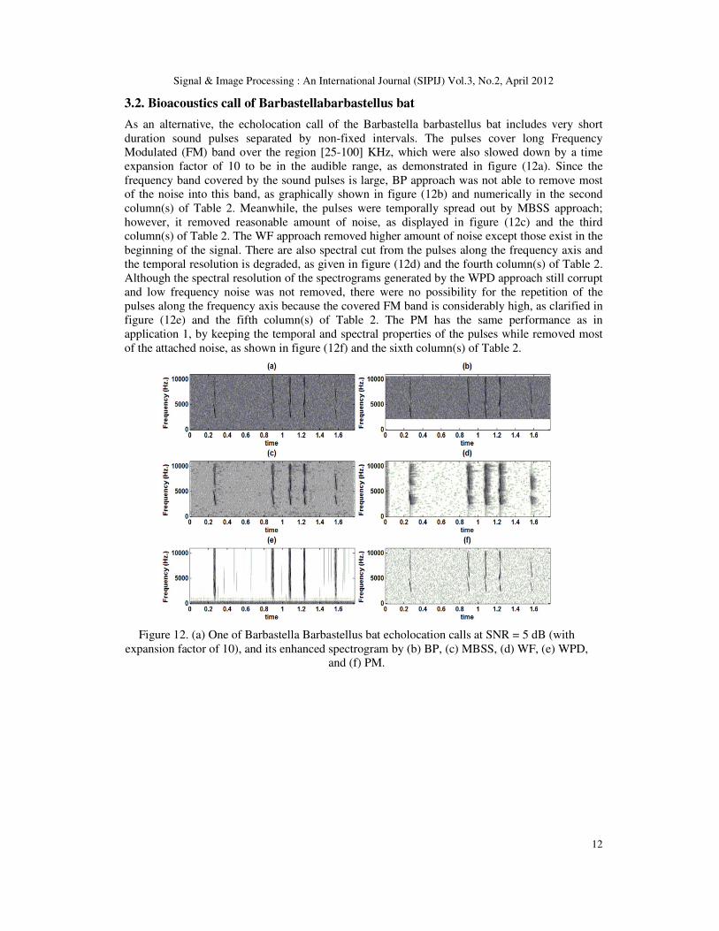
3.2. Bioacoustics call of Barbastellabarbastellus bat
As an alternative, the echolocation call of the Barbastella barbastellus bat includes very short
duration sound pulses separated by non-fixed intervals. The pulses cover long Frequency
Modulated (FM) band over the region [25-100] KHz, which were also slowed down by a time
expansion factor of 10 to be in the audible range, as demonstrated in figure (12a). Since the
frequency band covered by the sound pulses is large, BP approach was not able to remove most
of the noise into this band, as graphically shown in figure (12b) and numerically in the second
column(s) of Table 2. Meanwhile, the pulses were temporally spread out by MBSS approach;
however, it removed reasonable amount of noise, as displayed in figure (12c) and the third
column(s) of Table 2. The WF approach removed higher amount of noise except those exist in the
beginning of the signal. There are also spectral cut from the pulses along the frequency axis and
the temporal resolution is degraded, as given in figure (12d) and the fourth column(s) of Table 2.
Although the spectral resolution of the spectrograms generated by the WPD approach still corrupt
and low frequency noise was not removed, there were no possibility for the repetition of the
pulses along the frequency axis because the covered FM band is considerably high, as clarified in
figure (12e) and the fifth column(s) of Table 2. The PM has the same performance as in
application 1, by keeping the temporal and spectral properties of the pulses while removed most
of the attached noise, as shown in figure (12f) and the sixth column(s) of Table 2.
Figure 12. (a) One of Barbastella Barbastellus bat echolocation calls at SNR = 5 dB (with
expansion factor of 10), and its enhanced spectrogram by (b) BP, (c) MBSS, (d) WF, (e) WPD,
and (f) PM.
Page 13
Signal & Image Processing : An International Journal (SIPIJ) Vol.3, No.2, April 2012
13
Table 2. The subjective and objective measures for the spectrogram of Barbastella barbastellus call
enhanced by BP, MBSS, WF, WPD, and PM
(A) MOS
input
SNR noisy BP MBSS WF WPD PM
1 1 (1,1) 1.2 (0.9,1.5) 1.3 (1,1.6) 2.1 (1.9,2.3) 2.7 (2.4,3) 2 (1.7,2.3)
5 1.1 (0.9,1.3) 1.3 (1,1.6) 1.4 (1.1,1.7) 2.4 (2.1,2.7) 2.8 (2.5,3.1) 2.4 (2.1,2.7)
10 1.3 (0.9,1.7) 1.4 (1,1.8) 1.5 (1.2,1.8) 2.6 (2.3,2.9) 2.9 (2.7,3.1) 3.4 (3.1,3.7)
20 1.4 (1,1.7) 1.6 (1.3,1.9) 1.9 (1.7,2.1) 2.8 (2.4,3.2) 3.1 (2.9,3.3) 5 (5,5)
30 1.7 (1.4,2) 1.9 (1.7,2.1) 2.3 (2,2.6) 2.9 (2.7,3.1) 3.2 (2.9,3.5) 5 (5,5)
(B) SNR
input SNR noisy BP MBSS WF WPD PM
1 2.303 3.379 3.757 7.918 10.939 7.140
5 2.662 3.760 4.307 9.272 11.595 9.500
10 3.181 4.273 5.023 10.456 12.149 14.289
20 4.393 5.454 6.937 11.691 13.089 22.826
30 5.745 6.732 9.236 11.917 13.182 22.872
(C) SSNR
input SNR noisy BP MBSS WF WPD PM
1 1.763 1.886 1.931 2.510 2.843 2.320
5 1.804 1.930 1.995 2.782 2.961 2.592
10 1.864 1.989 2.078 3.182 3.077 3.158
20 2.004 2.126 2.312 5.017 3.376 6.814
30 2.163 2.278 2.659 4.233 3.628 3.386
(D) LSD
input SNR noisy BP MBSS WF WPD PM
1 0.942 1.015 0.600 0.194 0.278 0.610
5 0.943 0.888 0.466 0.140 0.191 0.485
10 0.859 0.715 0.417 0.209 0.171 0.360
20 0.571 0.535 0.244 0.201 0.124 0.121
30 0.407 0.367 0.135 0.392 0.173 0.195
(E) IS
input SNR noisy BP MBSS WF WPD PM
1 0.630 0.777 0.228 0.036 0.059 0.234
5 0.631 0.564 0.133 0.021 0.032 0.141
10 0.506 0.341 0.107 0.025 0.020 0.074
20 0.203 0.179 0.042 0.024 0.015 0.008
30 0.100 0.082 0.022 0.071 0.018 0.021
(F) AE
input SNR noisy BP MBSS WF WPD PM
1 57 57 56.6 6 16.27 57
5 57 57 56.8 9.31 19 57
10 57 57 56.8 14.54 34.52 57
20 57 57 56.85 21.13 47.33 57
30 57 57 56.85 30.46 54.18 57
3.3. Bioacoustics call of Vanellus vanellus bird
As an example for a multi harmonic sound stream in the human hearing range, the bioacoustics
call of Vanellus vanellus bird was investigated in the region bounded by 6 KHz. The sound
stream contains three FM long pulses with dominant frequencies around (1, 2.2, and 4) KHz;
respectively, followed by three downstream CF short pulses of fundamental frequencies around
(2, 3, and 4) KHz; respectively, as given in figure (13a). Enhancement by the BP approach did not
produce clear spectrogram, since the pulses cover much of the frequency axis, given high
Page 14
Signal & Image Processing : An International Journal (SIPIJ) Vol.3, No.2, April 2012
14
constraint to the rejected band by this approach, as shown in figure (13b) and the second
column(s) of Table 3. The enhanced spectrogram generated by the MBSS approach has
reasonable temporal resolution and degraded spectral resolution of the sound pulses, especially
for the downstream pulses which corrupted by high spectral distortion, as displayed in figure
(13c) and the third column(s) of Table 3.On the other hand, the temporal and spectral resolutions
of the spectrogram generated by WF approach are acceptable, although there is little spectral
leakage for the downstream pulses and initial sound noise (< 0.03 sec) were not removed, as
plotted in figure (13d) and the fourth column(s) of Table 3.Whereas the low frequency noise was
not enhanced by the WPD approach, many temporal bands of noises were removed. The
decomposition of the sound stream presented spectral mirrors of the weak harmonic patterns and
almost eliminated the downstream pulses, as demonstrated in figure (13e) and the fifth column(s)
of Table 3. Meanwhile, the enhanced spectrogram by PMre established high temporal and
spectral resolutions of the sound pulses, as indicated by the obtained LSD, with high distinction
from the attached noise, as designated by the obtained SNR and shown in figure (13f) and the
sixth column(s) of Table 3.
Figure 13. (a) One of Vanellus vanellus bird calls at SNR = 10 dB, and its enhanced spectrogram by
(b) BP, (c) MBSS, (d) WF, (e) WPD, and (f) PM.
Table 3. The subjective and objective measures for the spectrogram of Vanellus vanellus bird call
enhanced by BP, MBSS, WF, WPD, and PM (A) MOS
input
SNR noisy BP MBSS WF WPD PM
1 1 (1,1) 1.5 (1.2,1.8) 1.4 (1.1,1.7) 2 (1.7,2.3) 1.7 (1.4,2) 2.4 (2.1,2.7)
5 1.4 (1.1,1.7) 1.6 (1.3,1.9) 1.5 (1.2,1.8) 2.2 (1.9,2.5) 1.8 (1.4,2.2) 2.9 (2.7,3.1)
10 1.3 (1,1.6) 1.8 (1.4,2.2) 1.7 (1.3, 2.1) 2.4 (2.1,2.7) 1.9 (1.7,2.1) 3.7 (3.4,4)
20 1.5 (1.2,1.8) 1.9 (1.5,2.3) 1.8 (1.4,2.2) 2.6 (2.3,2.9) 1.9 (1.7,2.1) 4.7 (4.4,5)
30 1.6 (1.3,1.9) 2 (1.6,2.4) 1.8 (1.4,2.2) 2.7 (2.4,3) 1.9 (1.7,2.1) 5 (5,5)
(B) SNR
input SNR noisy BP MBSS WF WPD PM
1 1.651 2.635 2.489 3.591 2.895 4.371
5 1.941 2.843 2.689 4.046 3.180 5.414
10 2.207 3.153 2.912 4.452 3.317 6.807
20 2.662 3.532 3.108 4.771 3.422 9.078
30 2.814 3.605 3.163 4.884 3.339 9.480
Page 15
Signal & Image Processing : An International Journal (SIPIJ) Vol.3, No.2, April 2012
15
(C) SSNR
input SNR noisy BP MBSS WF WPD PM
1 1.688 1.801 1.784 1.925 1.896 2.001
5 1.721 1.825 1.807 1.995 1.989 2.121
10 1.752 1.861 1.833 2.059 2.036 2.283
20 1.804 1.904 1.856 2.119 2.120 2.564
30 1.822 1.913 1.863 2.162 1.991 2.621
(D) LSD
input SNR noisy BP MBSS WF WPD PM
1 1.172 1.083 0.982 1.220 1.009 0.790
5 1.042 0.938 0.876 1.141 0.907 0.505
10 0.988 0.888 0.537 1.028 0.783 0.537
20 0.814 0.783 0.753 1.012 0.587 0.267
30 0.718 0.714 0.515 0.968 0.579 0.267
(E) IS
input SNR noisy BP MBSS WF WPD PM
1 0.630 0.922 0.703 1.221 0.856 0.423
5 0.803 0.649 0.538 1.031 0.657 0.156
10 0.707 0.568 0.182 0.804 0.469 0.177
20 0.451 0.425 0.385 0.771 0.248 0.041
30 0.341 0.345 0.169 0.696 0.233 0.041
(F) AE
input SNR noisy BP MBSS WF WPD PM
1 8.47 8.47 14.63 10.32 3.13 8.51
5 8.47 8.47 12.51 10.3 3.82 8.51
10 8.47 8.47 9.78 9.46 4.17 8.51
20 8.47 8.47 9.12 8.72 7.12 8.51
30 8.47 8.47 8.65 8.19 7.44 8.51
From the pattern recognition point of view, different AE values to those of the original
spectrogram, reflect changing in the shape of some or all of the sound patterns, which result in
non-accuracy in further pattern recognition results. Unlike, similar AE values do not ensure the
shape of the sound pattern is similar to its original shape, but it may changes in a way that its
aspect ratio is constant.
4. Extended applications
The spectrograms obtained by the proposed method (PM) displayed how it is powerful and
consistent to enhance different structure bioacoustics calls. Therefore, these enhanced
spectrograms can be implemented in various post processing tasks. In this section, the three most
important implementations of the generated spectrogram by PM will be explored.
4.1. Power and frequency contours
The three variables of the enhanced spectrogram (i.e., time, frequency, and power spectrum) may
be plotted in different orders to obtain its power and/or frequency contours, as visible for the
bioacoustics call of Rhinolophus hipposideros bat (with expansion factor of 13) in figure (14),
after its spectrogram was enhanced by PM. The power contours provides an image of the
instantaneous power contents of the sound patterns and can be used for specific sound power
detection after calculating the areas enclosed by these contours. While the frequency contours
provide an image of the instantaneous frequency contents of the recorded bioacoustics call and
can be used for designing more reliable frequency filters.
Page 16
Signal & Image Processing : An International Journal (SIPIJ) Vol.3, No.2, April 2012
16
Figure 14. The enhanced (a) power and (b) frequency contours for Rhinolophus hipposideros bat
call
4.2. The enhanced wave form of the bioacoustics call
By transforming the enhanced spectrogram variables back to the time domain by Inverse Fast
Fourier Transform (IFFT), the enhanced wave form of the call is obtained, as given in figure
(15).The phase information obtained through the former Short Time Fourier Transform (STFT) is
used to reconstruct the enhanced wave form, following the flowchart of figure (15). The output
waveform can be used for reliable extraction of the bioacoustics temporal features suchlike zero
crossing rate, short time energy, temporal roll-off, and temporal spread of the sound patterns [1].
Figure 15. (upper) The 3D enhanced spectrogram for the bioacoustics call of Rhinolophus
hipposideros bat(with expansion factor of 13)and flow chart to reconstruct the waveform of its
sound stream. (bottom) the original and the reconstructed wave form of the sound stream;
respectively.
4.3. Bioacoustics calls classification
From the enhanced spectrogram, simple and reduced number of 1D featuresand/or 2D features
can be extracted for complete pattern recognition of the bioacoustics sound. The 1D features are
the signal features suchlike the covered frequency band(s), peak frequency, pulse duration,
interval between sound pulses, etc. while the 2D features are the image features suchlike
eccentricity and centroid. As a test case, a classifier of Vanellus vanellus, Parus major, and Sitta
Page 17
Signal & Image Processing : An International Journal (SIPIJ) Vol.3, No.2, April 2012
17
Canadensis birds has been constructed using the eccentricity (a/b) and the vertical coordinate of
the centroid (c) features, as shown in figure (16(ii)), extracted from the enhanced spectrogram of
each bird sound, as displayed in figure (16(i)). The classifier was trained by 26, 30, and 37 sound
patterns of the three birds; respectively, to define the rough dividing contours, given in figure
(16(iii)). Afterwards, the classifier was tested by another 7, 8, and 10 sound patterns of the three
birds; respectively, beside 7 patterns of Barbastella barbastellus bat and 5 patterns of Rhinolophus
Blasii bat, giving 94.59% classification accuracy (two sound patterns of Sitta Canadensis wrongly
detected as Vanellus vanellus), as plotted in figure (16(iii)). It may be realized that even simple
classifier can separate out the sound patterns into the correct bioacoustics source, providing that
distinctive features were selected and sufficient training patterns were used.
(i)
(ii)
(iii)
Figure 16. (i) Enhanced spectrogram for one of Sitta Canadensis bird contains the
strongestsound patterns, indicating how the eccentricity (a/b) and the vertical coordinate of
the centroid (c) are extracted for one of its sound patterns. The units of a and b are in pixeld,
and c in pixel number. (ii) Simple classifier structure with input of the two features, which
form the classification space, and the outputs are four classes for Vanellus vanellus, Parus
major, Sitta Canadensis , and unknown sounds. (iii) The classification space with three
dividing contours encounters the features of the three birds, respectively, at which the
surrounded region is for unknown sound features. The classification results also included
with two sound patterns of Sitta Canadensis wrongly detected as Vanellus vanellus.
5. Conclusion
Spectrogram reading provides a direct method for hands-on learning of the characteristics of
bioacoustics calls, therefore, a variety of enhancement techniques have been considered over the
past years to remove the attached noises. In this paper, a spectrogram enhancement method was
developed based on high accurate edge detection of the enclosed sound patterns and removing the
Page 18
Signal & Image Processing : An International Journal (SIPIJ) Vol.3, No.2, April 2012
18
surrounding noise. The crest factor was presented as a smoothed version of the spectrogram
image, avoiding the threshold problem of usual smoothing filters, suchlike Gaussian filter in
Canny edge detector. The proposed method was applied to enhance the limited dynamic range
spectrogram of different structure bioacoustics calls, in comparison to the four commonly used
enhancement approaches, which are band pass filter (BP), multi-band spectral subtraction
(MBSS), Wiener filter (WF), and wavelet packet decomposition (WPD) approaches. The
comparison was established on one subjective measure [mean opinion score] and four objective
measures [signal to noise ratio, segmental signal to noise ratio, log spectral distance, and Itakura
Saito]of the spectrograms obtained by the five methods at different SNR. The results showed that
the shorter the frequency band of FM pulse, the better the enhancement with BP and WPD. The
larger the upstream interval before the first pulse, the better the enhancement with WF. The
longer the CF pulse at high SNR, the better the enhancement with MBSS because it tends to
spread the patterns over time. Meanwhile, the proposed method produced highly efficient
enhanced spectrograms for all of the investigated calls.
The temporal and spectral resolutions of the spectrograms produced by the BP approach are of
high accuracy, since it does not operate a post processing to the full range of the noisy
spectrogram, but only rejects the band which estimated to be noise. This was not the case with
(MBSS, WF, and WPD) which post process the spectrograms for enhancement, results in
changing the temporal and/or spectral resolutions. In the meantime, the edge detection algorithm
of the proposed method was able to preserve the sound pulses into their almost original temporal
and spectral locations while processing the noisy spectrogram. This is very important issue for
any further pattern recognition assignment based on the enhanced spectrogram.
As a future aspect to this research work, an investigation will be made to avoid the loss of weak
patterns done through limiting the dynamic range of the spectrogram. Moreover, improving the
original spectrogram generation by adapting the applied STFT settings, this in correspondence
improves the enhanced spectrogram.
ACKNOWLEDGMENTS
All bioacoustics calls which have been used in this study are brought under written permission
from Aviosoft Bioacoustics GmbH, Berlin, Germany.
REFERENCES
[1] Hussein, W. B., Hussein, M.A.& Becker, T., (2009) “Application of audio signal processing in the
detection of the Red Palm Weevil”, Proceeding of European Signal Processing Conference
EUSIPCO2009, Glasgow, Scottland, 24-28.09.2009, pp 1597-1601.
[2] Obrist, M. K., Boesch, R. & Flückiger, P. F.,(2004) “Variability in echolocation call design of 26
Swiss bat species: consequences, limits and options for automated field identification with a
synergetic pattern recognition approach”. Mammalia, Vol.68, No. 4, pp 307-322.
[3] O'shaughnessy, D., (1987) “Speech Communication: Human and Machine”, Addison-Wesley
Publishing Co., Reading, MA, 1987, pp 56 - 106.
[4] Mallawaarachchi, A., Ong, S. H., Chitre, M., &Taylor, E, (2008) “Spectrogram denoising and
automated extraction of the fundamental frequency variation of dolphin whistles”. J. Acoust. Soc.
Am., Vol. 124, No. 2, pp 1-8.
[5] Oppenheim, Alan V., Schafer, Ronald W.& Buck, John A. (1999). “Discrete-time signal processing”.
Upper Saddle River, N.J., Prentice Hall, pp 468–471.
[6] Li, H., Zhang, Y. &Xu, D., (2010) ”Noise and Speckle Reduction in Doppler Blood Flow
Spectrograms Using an Adaptive Pulse-Coupled Neural Network”.EURASIP Journal on Advances in
Signal Processing, pp 1-11.
Page 19
Signal & Image Processing : An International Journal (SIPIJ) Vol.3, No.2, April 2012
19
[7] Ghanbari, Y., Karami, M. R.&Amelifard,B., (2004) “Improved multi-band spectral subtraction
method for speech enhancement”, Proceedings of the 6th ISTED International conference SIGNAL
AND IMAGE PROCESSING, pp225-230.
[8] Lampert, T. A. & O’keefe, S.E.M, (2010) “A survey of spectrogram track detection algorithms”.
Applied acoustics, Vol. 71, pp 87- 100.
[9] Mellinger, D. K., (2002). Ishmael 1.0 User’s Guide, Pacific Marine Enviromental Laboratory, Seattle,
USA.
[10] Liu, W. A., Miller, R.C., Merzenich, K.D., &Schreiner, C. E., (2003)“Acoustic variability and
distinguishability among mouse ultrasound vocalizations,” J. Acoust. Soc. Am., Vol. 114, pp 3412–
3422.
[11] Ding, H., Soon, I.Y., Koh, S.N.&Yeo, C.K., (2009) “A spectral filtering method based on hybrid
Wiener filters for speech enhancement”. Speech Communication, Vol. 51, pp 259–267.
[12] Gur, B. M., & Niezrecki, C., (2007). “Autocorrelation based denoising of manatee vocalizations using
the undecimated discrete wavelet transform,” J. Acoust. Soc. Am., Vol. 122, pp 188–199.
[13] Ghanbari, Y.&Karami, M.R., (2006)“A new approach for speech enhancement based on adaptive
thresholding of wavelet packets’ Speech communication, Vol. 48, pp 927-940.
[14] Chavan, M.S., Chavan, M.N., &Gaikwad, M.S., (2010) “Studies on Implementation of Wavelet for
Denoising Speech Signal”. International Journal of Computer Applications, Vol. 3, No.2,pp. 1-7
[15] Pandey, P.C., Pratapwar, S.S., &Lehana, P.K., (2004) ”Enhancement of Electrolaryngeal Speech by
Reducing Leakage Noise Using Spectral Subtraction with Quantile Based Dynamic Estimation of
Noise “.Proceeding of the 18th
international congress on acoustics ICA2004, pp. 3029-3032
[16] Sumithra, A., &Thanushkodi, B., (2009) “Performance Evaluation of Different Thresholding Methods
in Time AdaptiveWavelet Based Speech Enhancement”. IACSIT International Journal of Engineering
and Technology,Vol.1,No.5,pp 42-51.
[17] Kamath, S.& Loizou, P., (2002) “A Multi-band spectral subtraction method for Enhancing speech
corrupted by colored noise”, proceedings of ICASSP-2002, pp 37-43.
[18] Hermansky, H., Wan, E. A.& Avendano, Carlos, (1994) “Noise Suppression in Cellular
Communications”, in Proceedings IEEE IVTTA'94, pp 85-88.
[19] Kim, H.G., Obermayer, K., Bode, M.&Ruwisch, D., (2000) “real time noise cancelling based on
spectral minimum detection and diffusive gain factors”, in proceeding of 8th
Aust. Int. Conf. Speech
Sci. and Tech., pp 250-255.
[20] Tuthill, T.A., Sperry, R.H. & Parker, K.J., (1988) “Deviations from Rayleigh statistics in ultrasonic
speckle,” Ultrasonic Imaging, Vol. 10, No. 2, pp 81–89.
[21] Evans, N.D., Mason, J.S. & Roach, M.J., (2002) ”Noise Compensation using Spectrogram
Morphological Filtering”. In Proceeding of 4th
IASTED International Conference Signal Image
Processes, pp 157-161.
[22] Steinberg, R. &O'Shaughnessy,D., (2008) “Segmentation of a Speech Spectrogram using
Mathematical Morphology”, in proceeding Acoustics, Speech and Signal Processing, ICASSP 2008,
pp 1637 – 1640.
[23] Gillespie D., (2004) “Detection and classification of right whale calls using an ‘edge’ detector
operating on a smoothed spectrogram”. Can Acoust 2004, Vol. 32, pp39–47.
[24] Lin, B.S., Wu, H.D., Chong, F.C.&Chen, S.J., (2006) “Wheeze Recognition Based On 2d Bilateral
Filtering Of Spectrogram”. Biomed Eng Appl Basis Comm, Vol. 18, pp 128-137.
[25] Dugnol, B., Fernández, C., Galiano, G. &Velasco, J., (2007) “Wolves chorus noise reduction by
spectrogram image processing”, Signal Processing for Image Enhancement and Multimedia
Processing, Springer Verlag.
[26] Ohtake, Y., Belyaev, A.G.&Seidel, H.P., (2002) “Mesh smoothing by adaptive and anisotropic
Gaussian filter”. Proceeding of Vision, Modelling, and visualization 2002, pp 203-210.
Page 20
Signal & Image Processing : An International Journal (SIPIJ) Vol.3, No.2, April 2012
20
[27] Hussein, W. B., Hussein, M.A.,&Becker, T., (2010) "Detection of the Red Palm Weevil Using Its
Bioacoustics Features." Journal of Bioacoustics, Vol. 19, No. 3, pp 177-194.
[28] Hussein, W. B., Moaty, A. A, Hussein, M. A.& Becker, T., (2011) “A novel edge detection method
with application to the fat content prediction in marbled meat”. Pattern recognition, Vol. 44, No. 12,
pp 2959 – 2970.
[29] Eargle, J., (2005). “Handbook of recording engineering”, 4th
edition, Springer, pp 1-27.
[30] Deller, J.R., Hansen, J.H.L.& Proakis, J.G., (2000) “Discrete-Time Processing of Speech Signals”,
second ed., IEEE Press, New York.
[31] Quackenbush, S.R., Barnwell, T.B.& Clements, M.A, (1988) “Objective Measures of Speech
Quality”. Englewood Cliffs, NJ, Prentice-Hall.