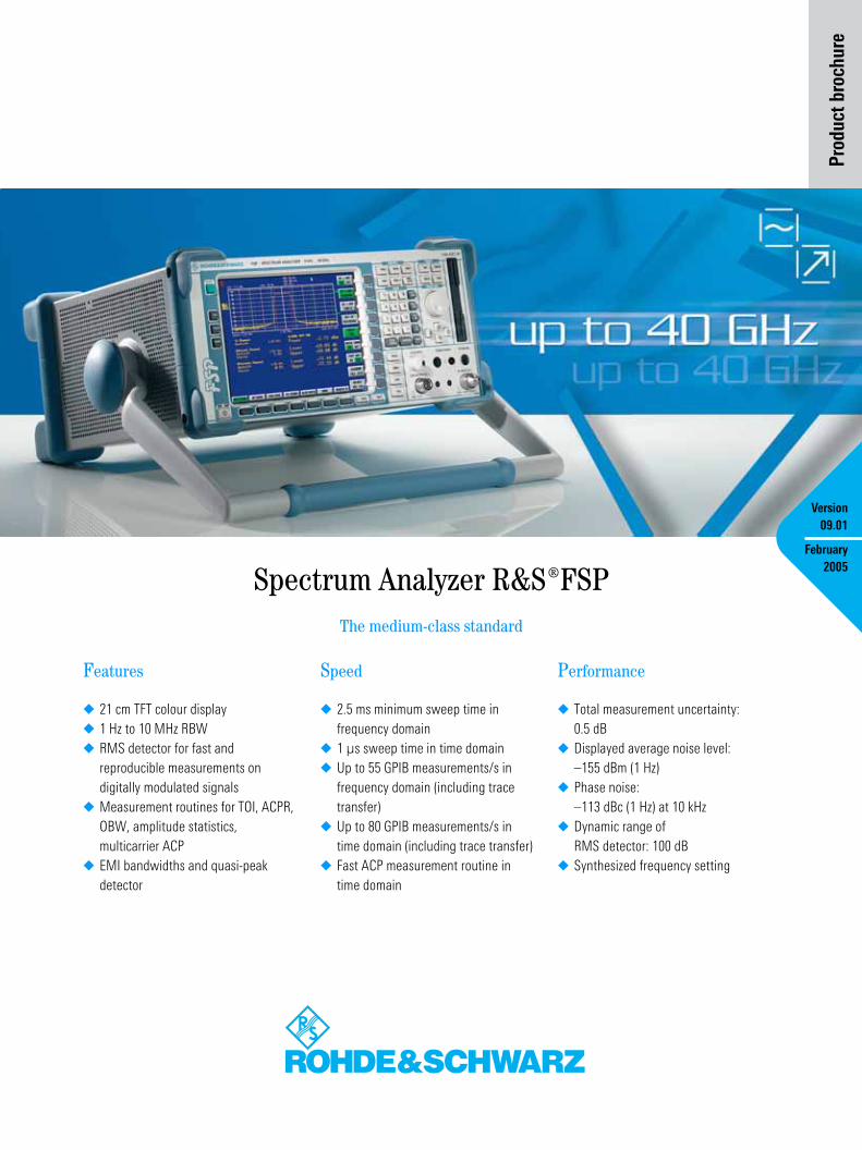
Product brochure Features ◆ 21 cm TFT colour display ◆ 1 Hz to 10 MHz RBW ◆ RMS detector for fast and reproducible measurements on digitally modulated signals ◆ Measurement routines for TOI, ACPR, OBW, amplitude statistics, multicarrier ACP ◆ EMI bandwidths and quasi-peak detector Speed ◆ 2.5 ms minimum sweep time in frequency domain ◆ 1 µs sweep time in time domain ◆ Up to 55 GPIB measurements/s in frequency domain (including trace transfer) ◆ Up to 80 GPIB measurements/s in time domain (including trace transfer) ◆ Fast ACP measurement routine in time domain Performance ◆ Total measurement uncertainty: 0.5 dB ◆ Displayed average noise level: –155 dBm (1 Hz) ◆ Phase noise: –113 dBc (1 Hz) at 10 kHz ◆ Dynamic range of RMS detector: 100 dB ◆ Synthesized frequency setting Spectrum Analyzer ¸FSP The medium-class standard Version 09.01 February 2005
Transcript
Pro
du
ct
bro
ch
ure
Spectrum Analyzer ¸FSP The medium-class standard
Version
09.01
February
2005
Features
◆ 21 cm TFT colour display◆ 1 Hz to 10 MHz RBW◆ RMS detector for fast and
reproducible measurements on digitally modulated signals
◆ 1 µs sweep time in time domain◆ Up to 55 GPIB measurements/s in
frequency domain (including trace transfer)
◆ Up to 80 GPIB measurements/s in time domain (including trace transfer)
◆ Fast ACP measurement routine in time domain
Performance
◆ Total measurement uncertainty: 0.5 dB
◆ Displayed average noise level:–155 dBm (1 Hz)
◆ Phase noise:–113 dBc (1 Hz) at 10 kHz
◆ Dynamic range ofRMS detector: 100 dB
◆ Synthesized frequency setting
The standard in the medium class …
Features
The Spectrum Analyzers ¸FSP are outstanding for their innovative measure-ments and a host of standard functions.
Instead of a wide choice of options, the ¸FSP offers as standard all the func-tions and interfaces expected from a state-of-the-art spectrum analyzer:
◆ Largest colour display in its class◆ Resolution bandwidths from 1 Hz to
10 MHz◆ Highly selective digital filters and FFT ◆ Quasi-peak detector and EMI
bandwidths◆ ACP and multicarrier ACP
measurements◆ Convenient documentation of results
as a hardcopy or file in PC-compatible formats
◆ Interfaces: GPIB, Centronics, RS-232-C, LAN (option), USB
◆ Automatic test routines for measuring TOI, OBW, phase noise and ACP(R)
◆ Split screen with separate settings and up to 3 traces per screen
◆ Editable limit lines including PASS/FAIL indication
◆ Fast measurements in the time do-main: minimum sweep time 1 µs
◆ Gated sweep for measurements on TDMA signals
2 Spectrum Analyzer ¸FSP
In addition, the ̧ FSP features the fol-lowing unique attributes as standard:
◆ RMS detector for fast and reproduc-ible power measurements on digitally modulated signals in frequency and time domain
◆ Statistical measurement functions for determining crest factor and CCDF (complementary cumulative distribu-tion function)
Featuring such a wealth of functions, the ¸FSP offers state-of-the-art spectrum analysis at an extremely attractive price/performance ratio.
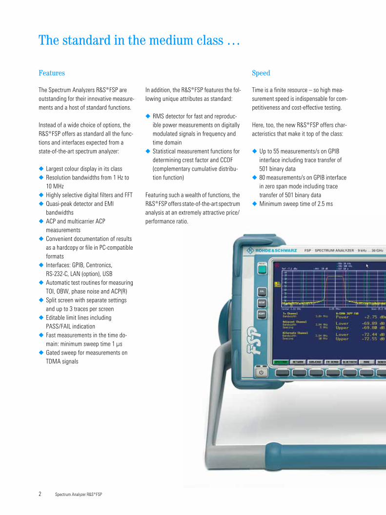
Speed
Time is a finite resource – so high mea-surement speed is indispensable for com-petitiveness and cost-effective testing.
Here, too, the new ¸FSP offers char-acteristics that make it top of the class:
◆ Up to 55 measurements/s on GPIB interface including trace transfer of 501 binary data
◆ 80 measurements/s on GPIB interface in zero span mode including trace transfer of 501 binary data
◆ Minimum sweep time of 2.5 ms
◆ 1 µs time domain measurements◆ Unique fast ACP mode for high-speed
ACPR measurements in time domain using the standard-compliant test filters
◆ List mode for fast, selective power measurements
With 100 measurements/s in manual operation and digital filters with a sweep time 2.5 times faster than comparable analog filters, the ¸FSP will also prove beneficial in the day-to-day tasks of product development.
Performance
Modern communication systems should provide optimum spectral efficiency at high data rates. For the 3rd generation of CDMA mobile radio systems currently under development, this is achieved through functions such as among other things, by high-precision power control.
The ¸FSP is the ideal partner in development and production, featuring low uncertainty in level measurement, as well as excellent RF characteristics:
◆ 0.5 dB total measurement uncertainty allows higher tolerances for the DUT, thus increasing production yield
◆ 0.07 dB linearity uncertainty (1 σ) is ideal for precise measurements, for example of gain control and ACPR
◆ RMS detector with >100 dB dynamic range measures power fast and accu-rately irrespective of the signal shape – almost like a thermal power sensor
◆ The displayed average noise level of typ. –155 dBm (1 Hz) is attained with-out the use of preamplifiers and thus without any reduction in dynamic range
◆ Typ. –145 dBc (1 Hz) phase noise at 10 MHz offset offers optimum condi-tions for ACPR measurements on WCDMA systems
Resolution bandwidths of up to 100 kHz are fully digital and provide – in addition to high selectivity – an ideal basis for accurate (adjacent-) channel power measurements owing to a maximum bandwidth deviation of 3%.
Spectrum Analyzer ̧ FSP 3
… now even faster
High-end characteristics …
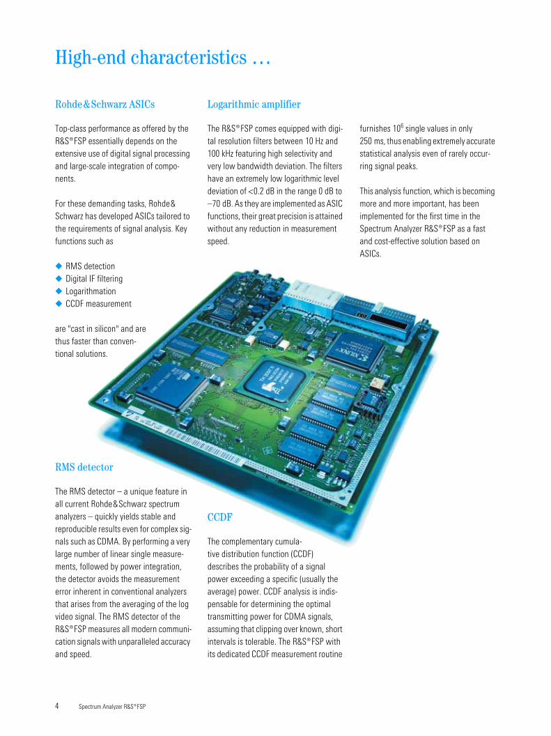
Rohde&Schwarz ASICs
Top-class performance as offered by the ¸FSP essentially depends on the extensive use of digital signal processing and large-scale integration of compo-nents.
For these demanding tasks, Rohde& Schwarz has developed ASICs tailored to the requirements of signal analysis. Key functions such as
◆ RMS detection◆ Digital IF filtering◆ Logarithmation◆ CCDF measurement
are "cast in silicon" and are thus faster than conven-tional solutions.
RMS detector
The RMS detector – a unique feature in all current Rohde&Schwarz spectrum analyzers – quickly yields stable and reproducible results even for complex sig-nals such as CDMA. By performing a very large number of linear single measure-ments, followed by power integration, the detector avoids the measurement error inherent in conventional analyzers that arises from the averaging of the log video signal. The RMS detector of the ¸FSP measures all modern communi-cation signals with unparalleled accuracy and speed.
4 Spectrum Analyzer ¸FSP
Logarithmic amplifier
The ¸FSP comes equipped with digi-tal resolution filters between 10 Hz and 100 kHz featuring high selectivity and very low bandwidth deviation. The filters have an extremely low logarithmic level deviation of <0.2 dB in the range 0 dB to –70 dB. As they are implemented as ASIC functions, their great precision is attained without any reduction in measurement speed.
CCDF
The complementary cumula-tive distribution function (CCDF) describes the probability of a signal power exceeding a specific (usually the average) power. CCDF analysis is indis-pensable for determining the optimal transmitting power for CDMA signals, assuming that clipping over known, short intervals is tolerable. The ¸FSP with its dedicated CCDF measurement routine
furnishes 106 single values in only 250 ms, thus enabling extremely accurate statistical analysis even of rarely occur-ring signal peaks.
This analysis function, which is becoming more and more important, has been implemented for the first time in the Spectrum Analyzer ¸FSP as a fast and cost-effective solution based on ASICs.
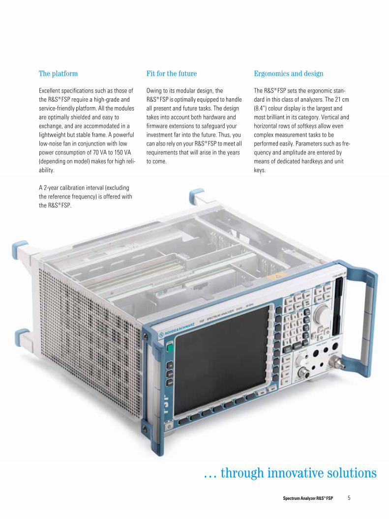
The platform
Excellent specifications such as those of the ¸FSP require a high-grade and service-friendly platform. All the modules are optimally shielded and easy to exchange, and are accommodated in a lightweight but stable frame. A powerful low-noise fan in conjunction with low power consumption of 70 VA to 150 VA (depending on model) makes for high reli-ability.
A 2-year calibration interval (excluding the reference frequency) is offered with the ¸FSP.
Fit for the future
Owing to its modular design, the ¸FSP is optimally equipped to handle all present and future tasks. The design takes into account both hardware and firmware extensions to safeguard your investment far into the future. Thus, you can also rely on your ̧ FSP to meet all requirements that will arise in the years to come.
… throu
Ergonomics and design
The ¸FSP sets the ergonomic stan-dard in this class of analyzers. The 21 cm (8.4”) colour display is the largest and most brilliant in its category. Vertical and horizontal rows of softkeys allow even complex measurement tasks to be performed easily. Parameters such as fre-quency and amplitude are entered by means of dedicated hardkeys and unit keys.
Spectrum Analyzer ̧ FSP 5
gh innovative solutions
Innovative solutions …
PRN
SGL
*
1 kHz
AVG
1 SA
5 kHz/ Span 50 kHzCenter 100 MHz
Att SWT 560 ms
VBW
RBW 300 Hz
* 0 dBRef -110 dBm
A
Sweep Ctr 33
Delta 2 [T1]
-5.26 dB
-13.10000000 kHz
Marker 1 [T1]
-120.74 dBm
100.00380000 MHz
2
1
-160
-155
-150
-145
-140
-135
-130
-125
-120
-115
-110
Noise figure measurement with Noise Measurement Software ¸FS-K30.
PRN
2 SA
1 RM *
500 µs/Center 835 MHz
SWT 5 ms
VIEW
SGL
AVG
Ref -8 dBm
VBW 10 MHz
Att 30 dB
B
RBW 3 MHz
VIEW
1 AP
A
100 ms/Center 835 MHz
VBW 10 MHz
RBW 3 MHz
SGL
SWT 1 sAtt 40 dBRef 10 dBm
-12
-17
-16
-15
-14
-13
-11
-10
-9
-80
-70
-60
-50
-40
-30
-20
-10
0
Sweep Ctr 999Sweep Ctr 999
Marker 1 [T1]
-10.75 dBm
1.700000 ms
Delta 2 [T2]
-4.37 dB
870.000000 µs
1
2
Sweep Ctr 999Sweep Ctr 999
Marker 1 [T1]
-10.75 dBm
1.700000 ms
Delta 2 [T2]
-4.37 dB
870.000000 µs
1
2
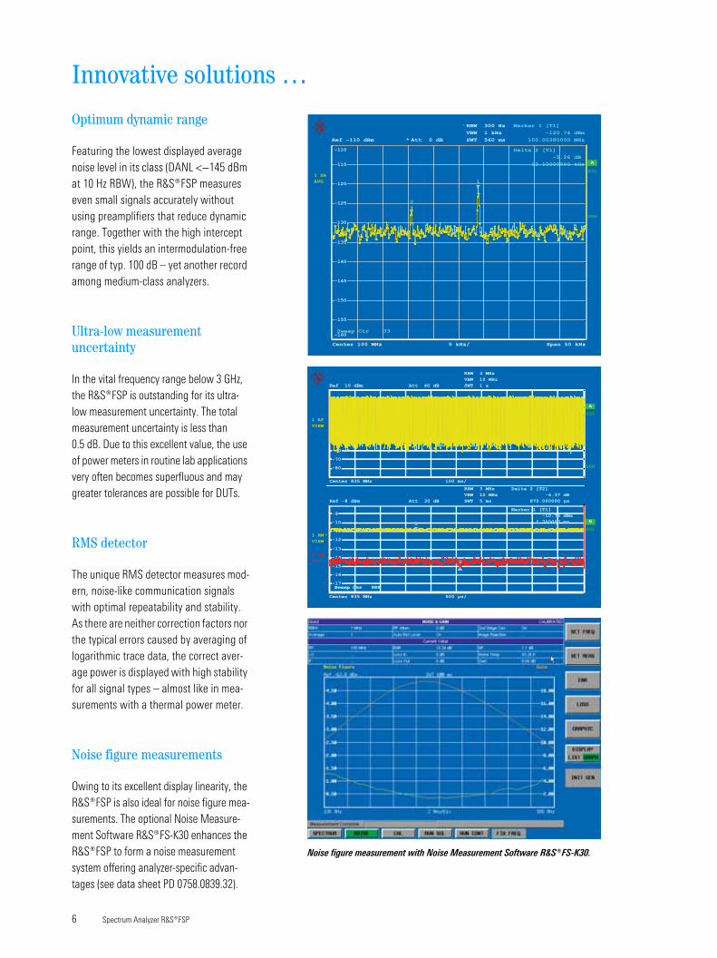
Optimum dynamic range
Featuring the lowest displayed average noise level in its class (DANL <−145 dBm at 10 Hz RBW), the ¸FSP measures even small signals accurately without using preamplifiers that reduce dynamic range. Together with the high intercept point, this yields an intermodulation-free range of typ. 100 dB – yet another record among medium-class analyzers.
Ultra-low measurement uncertainty
In the vital frequency range below 3 GHz, the ¸FSP is outstanding for its ultra-low measurement uncertainty. The total measurement uncertainty is less than 0.5 dB. Due to this excellent value, the use of power meters in routine lab applications very often becomes superfluous and may greater tolerances are possible for DUTs.
RMS detector
The unique RMS detector measures mod-ern, noise-like communication signals with optimal repeatability and stability. As there are neither correction factors nor the typical errors caused by averaging of logarithmic trace data, the correct aver-age power is displayed with high stability for all signal types – almost like in mea-surements with a thermal power meter.
Noise figure measurements
Owing to its excellent display linearity, the ¸FSP is also ideal for noise figure mea-surements. The optional Noise Measure-ment Software ¸FS-K30 enhances the ¸FSP to form a noise measurement system offering analyzer-specific advan-tages (see data sheet PD 0758.0839.32).
6 Spectrum Analyzer ¸FSP
… for research & development
CLRWR
A
Ref -13.5 dBm Att 20 dB
RBW 10 MHz
SWT 250 ms
Center 2.225 GHz 2 dB/ Mean Pwr + 20 dB
SGL
1 SA
PRN
1E-5
1E-4
1E-3
0.01
0.1
Complementary Cumulative Distribution Function
Samples 1000000
Trace 1
Mean Power -32.98 dBm
Peak Power -19.23 dBm
Crest Factor 13.75 dB
Marker 1 [T1]
0.010306703
7.72 dB
Marker 2 [T1]
0.001004205
9.92 dB
Marker 3 [T1]
0.000100206
11.60 dB
Marker 4 [T1]
0.000010132
12.96 dB
1
2
3
4
Phase noise mea-
surement with the
¸FSP.
CCDF of a WCDMA
signal.
Preprogrammed
standards for ACP
measurements.
PHN -0.688 dBm
PRN
VIEW
1 SA
*
SWT 2.5 ms
VBW 100 kHz
RBW 30 kHz
220 kHz/ Span 2.2 MHzCenter 100 MHz
* Att 10 dB
EXT
Ref 0 dBm
B
A
*
VBW 1 kHz
RBW 300 Hz
Span 22 kHzCenter 100 MHz 2.2 kHz/
*
VIEW
1 SA
SWT 245 msAtt 10 dBRef 0 dBm
-90
-80
-70
-60
-50
-40
-30
-20
-10
Marker 1 [T1 FXD]
-0.52 dBm
100.00000000 MHz
Delta 2 [T1 PHN]
-116.45 dBc/Hz
10.00000000 kHz1
2
Marker 1 [T1 FXD]
-0.83 dBm
100.00000000 MHz
Delta 2 [T1 PHN]
-125.83 dBc/Hz
1.00000000 MHz1
2
Marker 1 [T1 FXD]
-0.52 dBm
100.00000000 MHz
Delta 2 [T1 PHN]
-116.45 dBc/Hz
10.00000000 kHz1
2
Marker 1 [T1 FXD]
-0.83 dBm
100.00000000 MHz
Delta 2 [T1 PHN]
-125.83 dBc/Hz
1.00000000 MHz1
2
PHN
PHN -0.53 dBm
-90
-80
-70
-60
-50
-40
-30
-20
-10
PHN
Phase noise
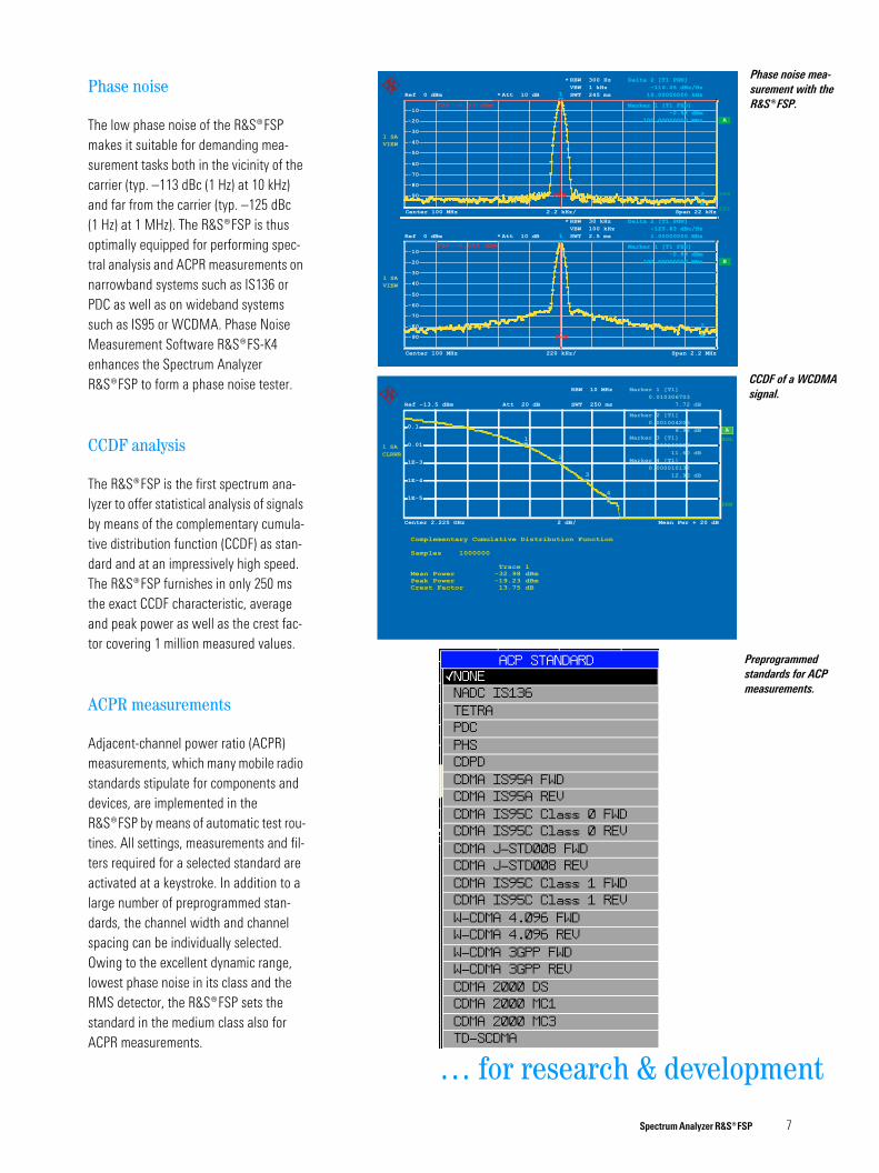
The low phase noise of the ¸FSP makes it suitable for demanding mea-surement tasks both in the vicinity of the carrier (typ. –113 dBc (1 Hz) at 10 kHz) and far from the carrier (typ. –125 dBc (1 Hz) at 1 MHz). The ¸FSP is thus optimally equipped for performing spec-tral analysis and ACPR measurements on narrowband systems such as IS136 or PDC as well as on wideband systems such as IS95 or WCDMA. Phase Noise Measurement Software ¸FS-K4 enhances the Spectrum Analyzer ¸FSP to form a phase noise tester.
CCDF analysis
The ¸FSP is the first spectrum ana-lyzer to offer statistical analysis of signals by means of the complementary cumula-tive distribution function (CCDF) as stan-dard and at an impressively high speed. The ¸FSP furnishes in only 250 ms the exact CCDF characteristic, average and peak power as well as the crest fac-tor covering 1 million measured values.
ACPR measurements
Adjacent-channel power ratio (ACPR) measurements, which many mobile radio standards stipulate for components and devices, are implemented in the ¸FSP by means of automatic test rou-tines. All settings, measurements and fil-ters required for a selected standard are activated at a keystroke. In addition to a large number of preprogrammed stan-dards, the channel width and channel spacing can be individually selected. Owing to the excellent dynamic range, lowest phase noise in its class and the RMS detector, the ¸FSP sets the standard in the medium class also for ACPR measurements.
Spectrum Analyzer ̧ FSP 7
Innovative solutions …
10
100
1.000
10000
100000
106
107
10 30 100 300 1000
Resolution bandwidth in Hz
Swee
p tim
e in
ms
FFT filter
Digital RBW
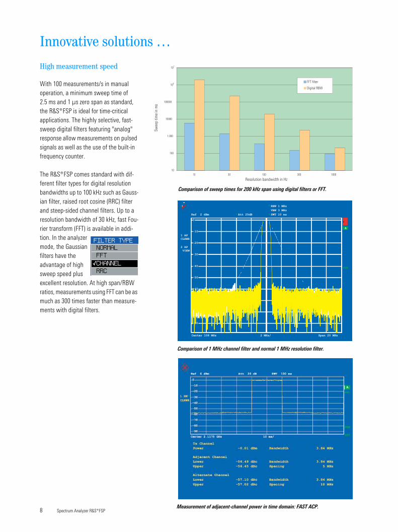
Comparison of sweep times for 200 kHz span using digital filters or FFT.
A
1 AP
CLRWR
Ref 2 dBm Att 25dB*
2 AP
VIEW
* RBW 1 MHz
VBW 3 MHz
SWT 10 ms*
*
PRN
-90
-80
-70
-30
0
-10
-20
-60
-50
-40
High measurement speed
With 100 measurements/s in manual operation, a minimum sweep time of 2.5 ms and 1 µs zero span as standard, the ¸FSP is ideal for time-critical applications. The highly selective, fast-sweep digital filters featuring "analog" response allow measurements on pulsed signals as well as the use of the built-in frequency counter.
The ¸FSP comes standard with dif-ferent filter types for digital resolution bandwidths up to 100 kHz such as Gauss-ian filter, raised root cosine (RRC) filter and steep-sided channel filters. Up to a resolution bandwidth of 30 kHz, fast Fou-rier transform (FFT) is available in addi-tion. In the analyzer mode, the Gaussian filters have the advantage of high sweep speed plus excellent resolution. At high span/RBW ratios, measurements using FFT can be as much as 300 times faster than measure-ments with digital filters.
8 Spectrum Analyzer ¸FSP
Center 108 MHz Span 20 MHz2 MHz/
Comparison of 1 MHz channel filter and normal 1 MHz resolution filter.
Measurement of adjacent-channel power in time domain: FAST ACP.
– 0.6
– 0.4
– 0.2
0
0.2
0.4
0.6
0 10 20 30 40 50 60 70 80 90
dB below reference level
Line
arity
unc
erta
inty
in d
B
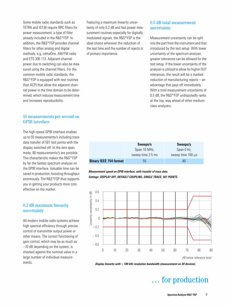
Display linearity with ≤ 100 kHz resolution bandwidth (measurement on 30 devices).
Measurement speed on GPIB interface, with transfer of trace data.
Settings: DISPLAY OFF, DEFAULT COUPLING, SINGLE TRACE, 501 POINTS.
Sweeps/s
Span 10 MHz, sweep time 2.5 ms
Sweeps/s
Span 0 Hz, sweep time 100 µs
Binary IEEE 754 format 55 80
Some mobile radio standards such as TETRA and IS136 require RRC filters for power measurement, a type of filter already included in the ¸FSP. In addition, the ¸FSP provides channel filters for other analog and digital methods, e.g. cdmaOne, AM/FM radio and ETS 300 113. Adjacent-channel power due to switching can also be mea-sured using the channel filters. For the common mobile radio standards, the ¸FSP is equipped with test routines (fast ACP) that allow the adjacent-chan-nel power in the time domain to be deter-mined, which reduces measurement time and increases reproducibility.
55 measurements per second on GPIB interface
The high-speed GPIB interface enables up to 55 measurements/s including trace data transfer of 501 test points with the display switched off. In the zero span mode, 80 measurements/s are possible. This characteristic makes the ¸FSP by far the fastest spectrum analyzer on the GPIB interface. Valuable time can be saved in production, boosting throughput enormously. The ¸FSP thus supports you in getting your products more cost-effective on the market.
0.2 dB maximum linearity uncertainty
All modern mobile radio systems achieve high spectral efficiency through precise control of transmitter output power or other means. The correct functioning of gain control, which may be as much as –70 dB depending on the system, is checked against the nominal value in a large number of individual measure-ments.
Featuring a maximum linearity uncer-tainty of only 0.2 dB and fast power mea-surement routines especially for digitally modulated signals, the ¸FSP is the ideal choice wherever the reduction of the test time and the number of rejects is of primary importance.
0.5 dB total measurement uncertainty
Measurement uncertainty can be split into the part from the instrument and that introduced by the test setup. With lower uncertainty of the spectrum analyzer, greater tolerances can be allowed for the test setup. If the lower uncertainty of the analyzer is utilized to allow for higher DUT tolerances, the result will be a marked reduction of manufacturing rejects – an advantage that pays off immediately. With a total measurement uncertainty of 0.5 dB, the ¸FSP undisputedly ranks at the top, way ahead of other medium-class analyzers.
Spectrum Analyzer ̧ FSP 9
… for production
Innovative solutions …
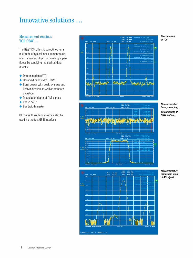
Measurement
of TOI.
Measurement of
burst power (top).
Determination of
OBW (bottom).
PRN
SGL
AVG
1 SA
*
SWT 10 ms
VBW 30 kHz
RBW 10 kHz
*Att 20 dB
77.7 kHz/ Span 777 kHzCenter 2.2 GHz
Ref 10 dBm
A
-90
-80
-70
-60
-50
-40
-30
-20
-10
0
10
Sweep Ctr 10
Marker 3 [T1 TOI]
-55.49 dBm
2.19970008 GHz
Marker 1 [T1 TOI]
2.60 dBm
2.19990054 GHz
Marker 2 [T1 TOI]
2.59 dBm
2.20010101 GHz
Marker 4 [T1 TOI]
-54.80 dBm
2.20030148 GHz
TOI 31.47 dBm
3
1 2
4
PRN
1 SA
SGL
CLRWR
Att 60 dBRef 30 dBm SWT 5 ms
VBW 10 MHz
RBW 3 MHz
-8.91 dBm
3.120000 ms
POWER [T1]
PEAK -7.01 dBm
RMS -16.65 dBm
MEAN -18.11 dBm
SDEV 2.47 dB1
Marker 1 [T1]
-8.91 dBm
3.120000 ms
POWER [T1]
PEAK -7.01 dBm
RMS -16.65 dBm
MEAN -18.11 dBm
SDEV 2.47 dB1
T2
T1-60
-50
-40
-30
-20
-10
0
10
20
Measurement routines TOI, OBW …
The ¸FSP offers fast routines for a multitude of typical measurement tasks, which make result postprocessing super-fluous by supplying the desired data directly:
◆ Determination of TOI◆ Occupied bandwidth (OBW)◆ Burst power with peak, average and
RMS indication as well as standard deviation
◆ Modulation depth of AM signals◆ Phase noise◆ Bandwidth marker
Of course these functions can also be used via the fast GPIB interface.
10 Spectrum Analyzer ¸FSP
Measurement of
modulation depth
of AM signal.
SGL
*
VBW 300 kHz
RBW 30 kHz
500 kHz/ Span 5 MHzCenter 835 MHz
Ref -30 dBm Att 10 dB * SWT 1 s
*1 RM
CLRWR
500 µs/Center 835 MHz
Temp 1 [T1 OBW]
-90.85 dBm
832.50000000 MHz
Marker 1 [T1 OBW]
-33.42 dBm
835.00000000 MHz
OBW 1.28000000 MHz
Temp 2 [T1 OBW]
-39.57 dBm
835.64000000 MHz
Temp 1 [T1 OBW]
Temp 2 [T1 OBW]
-39.57 dBm
835.64000000 MHz
T1
1
T2T1 T2Temp 1 [T1 OBW]
Marker 1 [T1 OBW]
-33.42 dBm
835.00000000 MHz
OBW 1.28000000 MHz
Temp 2 [T1 OBW]
-39.57 dBm
835.64000000 MHz
Temp 1 [T1 OBW]
Temp 2 [T1 OBW]
-39.57 dBm
835.64000000 MHz
T1
1
T2T1 T2
-85
-80
-75
-70
-65
-60
-55
-50
-45
-40
-35
B
Date: 11.AUG.1999 16:18:35a
PRN
SGL
CLRWR
1 AP
* VBW 300 kHz
RBW 100 Hz
300 Hz/ Span 3 kHzCenter 454.85kHz
SWT 300 ms
EXT
Att 20 dBRef 10 dBm
Mix -10 dBm
A
MD
Delta 3 [T1 MOD]
-46.40 dB
-1.00200000 kHz
Marker 1 [T1MOD]
2.02 dBm
455.00000000kHz
Delta 2 [T1 MOD]
-46.35 dB
1.00200000 kHz
EPTH 0.960%
3
1
2
Comment A: DUT = PWRA2117.5
-80
-70
-60
-50
-40
-30
-20
-10
0
10
-90
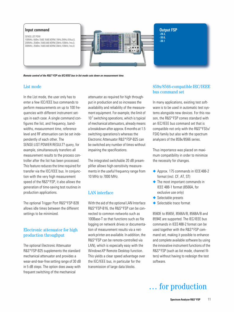
Remote control of the ¸FSP via IEC/IEEE bus in list mode cuts down on measurement time.
In the List mode, the user only has to enter a few IEC/IEEE bus commands to perform measurements on up to 100 fre-quencies with different instrument set-ups in each case. A single command con-figures the list, and frequency, band-widths, measurement time, reference level and RF attenuation can be set inde-pendently of each other. The SENSE:LIST:POWER:RESULT? query, for example, simultaneously transfers all measurement results to the process con-troller after the list has been processed. This feature reduces the time required for transfer via the IEC/IEEE bus. In conjunc-tion with the very high measurement speed of the ¸FSP, it also allows the generation of time-saving test routines in production applications.
The optional Trigger Port ¸FSP-B28 allows idle times between the different settings to be minimized.
Electronic attenuator for high production throughput
The optional Electronic Attenuator ¸FSP-B25 supplements the standard mechanical attenuator and provides a wear-and-tear-free setting range of 30 dB in 5 dB steps. The option does away with frequent switching of the mechanical
attenuator as required for high through-put in production and so increases the availability and reliability of the measure-ment equipment. For example, the limit of 107 switching operations, which is typical of mechanical attenuators, already means a breakdown after approx. 6 months at 1.5 switching operations/s whereas the Electronic Attenuator ¸FSP-B25 can be switched any number of times without impairing the specifications.
The integrated switchable 20 dB pream-plifier allows high-sensitivity measure-ments in the useful frequency range from 10 MHz to 7000 MHz.
LAN interface
With the aid of the optional LAN Interface ¸FSP-B16, the ¸FSP can be con-nected to common networks such as 100Base-T so that functions such as file logging on network drives or documenta-tion of measurement results via a net-work printer are available. In addition, the ¸FSP can be remote-controlled via LAN), which is especially easy with the WindowsXP Remote Desktop function. This yields a clear speed advantage over the IEC/IEEE bus, in particular for the transmission of large data blocks.
…
859x/8566-compatible IEC/IEEE bus command set
In many applications, existing test soft-ware is to be used in automatic test sys-tems alongside new devices. For this rea-son, the ¸FSP comes standard with an IEC/IEEE bus command set that is compatible not only with the ¸FSEx/FSIQ family but also with the spectrum analyzers of the 859x/8566 series.
Thus importance was placed on maxi-mum compatibility in order to minimize the necessity for changes.
◆ Approx. 175 commands in IEEE488-2 format (incl. CF, AT, ST)
◆ The most important commands in IEEE 488-1 format (8566A, for exclusive use only)
◆ Selectable presets◆ Selectable trace format
8560E to 8565E, 8566A/B, 8568A/B and 8594E are supported. The IEC/IEEE bus commands in IEEE488-2 format can be used together with the ¸FSP com-mand set, making it possible to enhance and complete available software by using the innovative instrument functions of the ¸FSP (such as list mode, channel fil-ters) without having to redesign the test software.
Spectrum Analyzer ̧ FSP 11
for production
Innovative solutions …
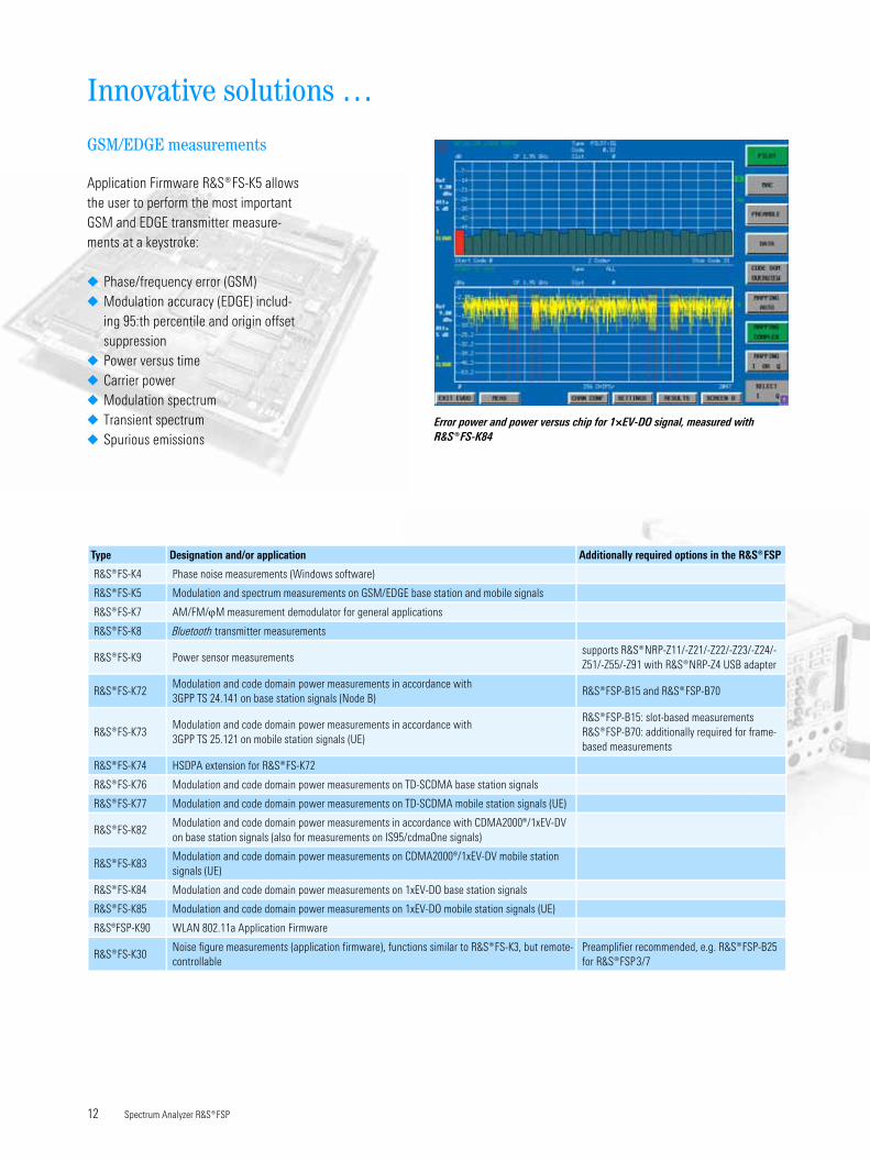
Error power and power versus chip for 1×EV-DO signal, measured with
¸FS-K84
GSM/EDGE measurements
Application Firmware ¸FS-K5 allows the user to perform the most important GSM and EDGE transmitter measure-ments at a keystroke:
¸FS-K5 Modulation and spectrum measurements on GSM/EDGE base station and mobile signals
¸FS-K7 AM/FM/ϕM measurement demodulator for general applications
¸FS-K8 Bluetooth transmitter measurements
¸FS-K9 Power sensor measurementssupports ¸NRP-Z11/-Z21/-Z22/-Z23/-Z24/-Z51/-Z55/-Z91 with ¸NRP-Z4 USB adapter
¸FS-K72Modulation and code domain power measurements in accordance with 3GPP TS 24.141 on base station signals (Node B)
¸FSP-B15 and ¸FSP-B70
¸FS-K73Modulation and code domain power measurements in accordance with3GPP TS 25.121 on mobile station signals (UE)
¸FSP-B15: slot-based measurements¸FSP-B70: additionally required for frame-based measurements
¸FS-K74 HSDPA extension for ¸FS-K72
¸FS-K76 Modulation and code domain power measurements on TD-SCDMA base station signals
¸FS-K77 Modulation and code domain power measurements on TD-SCDMA mobile station signals (UE)
¸FS-K82Modulation and code domain power measurements in accordance with CDMA2000®/1xEV-DV on base station signals (also for measurements on IS95/cdmaOne signals)
¸FS-K83Modulation and code domain power measurements on CDMA2000®/1xEV-DV mobile station signals (UE)
¸FS-K84 Modulation and code domain power measurements on 1xEV-DO base station signals
¸FS-K85 Modulation and code domain power measurements on 1xEV-DO mobile station signals (UE)
R&S®FSP-K90 WLAN 802.11a Application Firmware
¸FS-K30Noise figure measurements (application firmware), functions similar to ¸FS-K3, but remote-controllable
Preamplifier recommended, e.g. ¸FSP-B25 for ¸FSP3/7
Spectrum Analyzer ̧ FSP 13
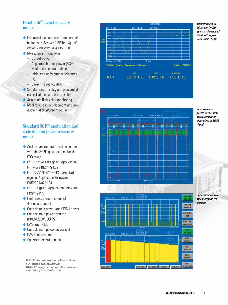
Code domain power
measurement ver-
sus slot.
Measurement of
initial carrier fre-
quency tolerance of
Bluetooth signal
with ¸FS-K8.
Simultaneous
power versus time
measurement on
eight slots of EDGE
signal.
Bluetooth® signal measure-ments
◆ Enhanced measurement functionality in line with Bluetooth RF Test Specifi-cation (Bluetooth SIG) Rev. 0.91
◆ Measurement functions– Output power– Adjacent channel power (ACP)– Modulation characteristics– Initial carrier frequency tolerance
(ICTF)– Carrier frequency drift
◆ Simultaneous display of traces and all numerical measurement results
◆ Automatic limit value monitoring◆ Ideal for use in development and pro-
duction of Bluetooth modules
Standard 3GPP modulation and code domain power measure-ments
◆ Adds measurement functions in line with the 3GPP specifications for the FDD mode
◆ For BTS/Node B signals: Application Firmware ¸FS-K72
◆ For CDMA2000®/3GPP3 base station signals: Application Firmware ¸FS-K82/-K84
◆ For UE signals: Application Firmware ¸FS-K73
◆ High measurement speed of 4 s/measurement
◆ Code domain power and CPICH power◆ Code domain power and rho
(CDMA2000®/3GPP2)◆ EVM and PCDE◆ Code domain power versus slot◆ EVM/code channel◆ Spectrum emission mask
BLUETOOTH is a trademark owned by Bluetooth SIG, Inc., USA and licensed to Rohde & Schwarz.CDMA2000® is a registered trademark of the Telecommuni-cations Industry Association (TIA -USA)
14 Spectrum Analyzer ¸FSP
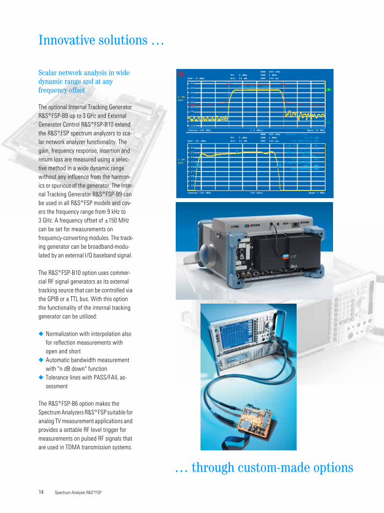
Scalar network analysis in wide dynamic range and at any frequency offset
The optional Internal Tracking Generator ¸FSP-B9 up to 3 GHz and External Generator Control ¸FSP-B10 extend the ¸FSP spectrum analyzers to sca-lar network analyzer functionality. The gain, frequency response, insertion and return loss are measured using a selec-tive method in a wide dynamic range without any influence from the harmon-ics or spurious of the generator. The Inter-nal Tracking Generator ¸FSP-B9 can be used in all ¸FSP models and cov-ers the frequency range from 9 kHz to 3 GHz. A frequency offset of ±150 MHz can be set for measurements on frequency-converting modules. The track-ing generator can be broadband-modu-lated by an external I/Q baseband signal.
The ¸FSP-B10 option uses commer-cial RF signal generators as its external tracking source that can be controlled via the GPIB or a TTL bus. With this option the functionality of the internal tracking generator can be utilized:
◆ Normalization with interpolation also for reflection measurements with open and short
◆ Automatic bandwidth measurement with "n dB down" function
◆ Tolerance lines with PASS/FAIL as-sessment
The ¸FSP-B6 option makes the Spectrum Analyzers ̧ FSP suitable for analog TV measurement applications and provides a settable RF level trigger for measurements on pulsed RF signals that are used in TDMA transmission systems.
… through custom-made options
Innovative solutions …
SWT 100 ms
TG 0 dBm
TG 0 dBm
Ref -21 dBm
Center 161 MHz Span 7 MHz700 kHz/
RBW 300 kHz
VBW 1 MHz
SWT 100 ms
AVG
1 SA
AVG
Att 10 dB
A
B
Att 10 dB*
RBW 300 kHz
VBW 1 MHz
Ref -4 dBm
Center 160 MHz Span 12 MHz1.2 MHz/
1 SA
PRN
-30
-29
-28
-27
-26
-25
-24
-23
-22
-100
-90
-80
-70
-60
-50
-40
-30
-20
-10
Temp 1 [T1 ndB]
-83.47 dBm
157.500000000 MHz
Marker 1 [T1]
-23.12 dBm
159.990000000 MHz
ndB [T1] 3.00 dB
BW 4.130000000 MHz
Temp 2 [T1 ndB]
-26.17 dBm
162.106000000 MHz
Temp 1 [T1 ndB]
Temp 2 [T1 ndB]
-26.17 dBm
162.106000000 MHz
T1
1
T2T1 T2
LIMIT CHECK PASS
Temp 2 [T1 ndB]
-26.17 dBm
162.106000000 MHz
Temp 2 [T1 ndB]
T1
1
T2T1
160
Complete measurement solutions …
Environmental compatibility
◆ Fast and easy disassembly◆ Small number of materials◆ Compatibility of materials◆ Easy identification of substances
through appropriate marking (plastics)
◆ Recycling of enclosure
…
Open for the PC world …
◆ PC-compatible screenshots, no conversion software needed
◆ Windows printer support◆ USB interface for connecting PC
Displayed average noise level with optional on (option ¸FSP-B25 electronic attenuator on)
–152 dBm –152 dBm – – –
Total measurement uncertainty, f < 3 GHz 0.5 dB
Linear level display 0.2 dB (0 dB to –70 dB)
Spectrum Analyzer ̧ FSP 16
Certified Quality System
ISO 9001DQS REG. NO 1954 QM
Certified Environmental System
ISO 14001DQS REG. NO 1954 UM
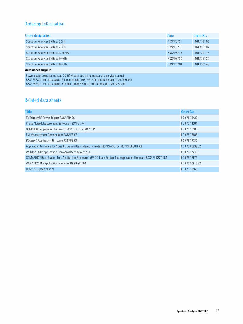
Ordering information
Related data sheets
Order designation Type Order No.
Spectrum Analyzer 9 kHz to 3 GHz ¸FSP3 1164.4391.03
Spectrum Analyzer 9 kHz to 7 GHz ¸FSP7 1164.4391.07
Spectrum Analyzer 9 kHz to 13.6 GHz ¸FSP13 1164.4391.13
Spectrum Analyzer 9 kHz to 30 GHz ¸FSP30 1164.4391.30
Spectrum Analyzer 9 kHz to 40 GHz ¸FSP40 1164.4391.40
Accessories supplied
Power cable, compact manual, CD-ROM with operating manual and service manual.¸FSP30: test port adapter 3.5 mm female (1021.0512.00) and N female (1021.0535.00)¸FSP40: test port adapter K female (1036.4770.00) and N female (1036.4777.00)
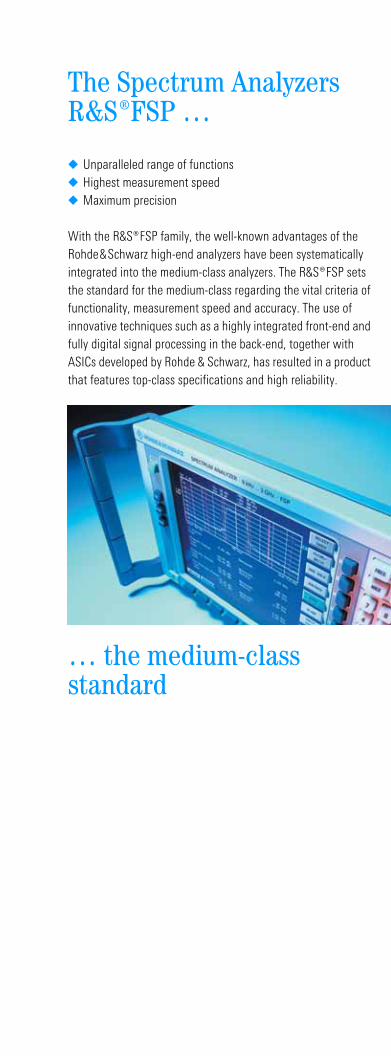
◆ Unparalleled range of functions◆ Highest measurement speed◆ Maximum precision
With the ¸FSP family, the well-known advantages of the Rohde&Schwarz high-end analyzers have been systematically integrated into the medium-class analyzers. The ¸FSP sets the standard for the medium-class regarding the vital criteria of functionality, measurement speed and accuracy. The use of innovative techniques such as a highly integrated front-end and fully digital signal processing in the back-end, together with ASICs developed by Rohde & Schwarz, has resulted in a product that features top-class specifications and high reliability.
… the medium-class standard
Schnittkante für die Einklappseite
Position: Einklapper hängt an der Tite-seite!
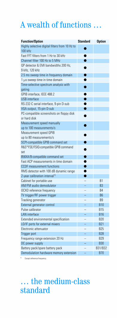
A wealth of functions …
… the medium-class standard
Function/Option Standard Option
Highly selective digital filters from 10 Hz to 100 kHz