Speed and force control of a hydraulic press using proportional valve
Maher Yahya Salloom1, Ehab Bassam Abdulqader2
1Maher S., Mechatronics Engineering Department, Al-Khwarizmi College of Engineering, University Of Baghdad,
2Ehab A., Mechatronics Engineering Department, Al-Khwarizmi College of Engineering, University Of Baghdad, Baghdad, Iraq
---------------------------------------------------------------------***---------------------------------------------------------------------Abstract - In this work, a smart system has been
implemented. The system used proportional pressure
control valve, proportional directional control valve and
also electronic pressure sensor through Arduino controller.
It is programmed in a way that performs the relationship
between pressure required to bend the material and its
parameters. The system of this work was simulated by
simulation program (Automation Studio) to make sure the
function of it is work properly. Copper alloy with different
thicknesses were tested in this work.
A laboratory system was built to shows the system's work
to ensure the performance and design of the system. As a
result, a proportional relationship between pressure
sensors, ultrasonic sensor with the proportional valves has
been obtained. The conclusion of this work the force and
speed can be controlled with respect to material thickness
and the type of the alloy. Finally it can be design and
implement a smart press working with automation system.
Key Words: proportional directional control valve, proportional pressure relief valve, force control, speed control, simulation using automation studio.
1. INTRODUCTION The hydraulic press is one of the oldest tools that had been
used in metal forming. The force of the press is regulated
by the pressure relief valve manually. This process need to
shut off the hydraulic system and then set the relief valve
to the required pressure. The speed of the hydraulic
cylinder stroke is regulated using the throttle valve
manually. Traditional presses that regulated manually
requires the presence of monitoring workers continuously
near the press machine, when changing the material that
have to be bent.
The objective of this work is to control the speed and force
of the press machine and working automatically.
Hydraulics plays a very important role in the lives of
people. Its importance can be seen from the fact that it is
considered to be one part of the muscle that moves the
industry, the place held by hydraulics in modern
automation technology illustrates the wide range of
applications for which it can be used, Today, hydraulic
term was understood as the transmission and control of
force and movement by means of fluid.
Press working techniques utilizing large quantities of
economical tooling equipment design and it less time, high
accuracy and less cost cold working of mild steel and other
ductile materials. The component produced range over an
extremely wide field and is used throughout industry for
economical production of quantities of pressing;
consideration has to be given to the rate of production, the
cost of the press tool to be employed. Press may be
defined as the chip less manufacturing process by which
various components are made from sheet. Mostly press
use fabricated parts of set shape with thin walls. It uses
large force by press tools for minimum time interval of
production which result in cutting or shaping the sheet
metal work piece in to the desired shape. In the early days,
metal forming press use simple crank and lever
mechanism that convert rotating motion into linear
motion with the help of punch/ram. The rotating motion
achieved by motor and linear motion achieved by punch
or ram, punch applied on work piece [1].The block
diagram of this work is shown in figure (1).
Fig -1: block diagram of proportional control system for speed and force controlling
International Research Journal of Engineering and Technology (IRJET) e-ISSN: 2395 -0056
The required forces that carry out the bend in materials depend on the punch and die geometry, also depending on the thickness, strength and the length of sheet. The required force of bending can be obtained from the following equation [8].
Which is the force of bending (N); is the sheet metal tensile strength (MPa); is the width of work piece in direction of the bending axis (mm); is the thickness of the stock (mm); and is the dimension of the die opening; bending constant, it value chosen depend on the type
of die, where for V type bending and edge
type bending .
A hydraulic press is a machine using a hydraulic cylinder to generate a compressive force. Frame and cylinder are the main components of the hydraulic press. In this project press frame and cylinder are designed by the design procedure. Press frame and cylinder are analyzed to improve its performance and quality for press working operation. Structural analysis has become an integral part of the product design [2]. As techniques to control the force of the system, using variable speed drive uses a variable speed electric motor to drive a hydraulic fixed displacement pump. By adjust the rotational speed of the electric-motor to regulate the hydraulic pump flow rate, to produce the required force [3]. Electro-hydraulic pump controlled system was driven by a variable rotational speed AC servo motor to achieve high response and high efficiency. The velocity controlled in a hydraulic injection molding machine. A constant displacement axial piston pump merged with the AC servo motor is developed in this research as the high response electro-hydraulic pump controlled system. A fuzzy control system was used to control the system [7]. In traditional presses the employers has to determine the
optimum force and speed required for each sample before
bending. The pressure was set manually by using manual
relief valve and the speed was selected by using throttle to
determine the amount of fluid follow. In this research
proportional valve was used with modified control system
to determine the force and speed required for each
sample. The objective of this research is to design and
analysis of electro-hydraulic control system for speed
and force control of hydraulic press using proportional
valves , to achieve the above objectives .The following
points are to be investigated :-
1- Propose variable speed and force of a hydraulic press using proportional technology. 2- To study the performance of the hydraulic press theoretical and practical. 3- Intelligent control system design using sensors to make the works is more safety.
2. SYSTEM DESIGN In the beginning any hydraulic system works mainly in three stages. It begins with mechanical energy input that will be converted in to fluid power with hydraulic pumps. Then, this fluid with its energy goes through pipes or connectors and necessary hydraulic control valves. Finally the fluid power converted into mechanical power with actuators devices such as cylinders [9]. The hydraulic system is shown in figure (2) and figure (3). It is consisting of: hydraulic power unit, hydraulic cylinder, proportional directional control valve, proportional pressure relief valve, pressure sensors, and ultrasonic sensor. The system was designed to control the force of the press on the samples by controlling the pressure of the system using the proportional pressure relief valve. And the speed of the stroke of the cylinder is controlled by controlling the amount of the fluid flows to the actuator, the fluid controlled by using proportional directional control valve which controls the direction and the amount of flow at the same time
Fig -2: The Electro-hydraulic press machine system
Fig -3: The Electro-hydraulic system
International Research Journal of Engineering and Technology (IRJET) e-ISSN: 2395 -0056
STUDIO Automation Studio (AS) package was developed in (2003) by (FAMIC Technologies Inc/Canada) to contain comprehensive libraries of hydraulic, pneumatic, ladder logic, and digital electronic symbols. This package is completely integrated software package that allows the user to design, simulate and animate circuits consisting of various automation technologies [6]. Proportional hydraulic press control system of force and speed control was built and simulated with this program. All components and parameters of the system have been selected and connected as in the actual system in the project work sheet as shown in figure (4).
Fig -4: the simulation process of the electro hydraulic control system of the press machine
4. ELECTRONIC CIRCUIT WITH ARDUINO UNO
BOARD The circuits are designed and built experimentally by the researcher using simple electronic components and amplifier cards of the proportional valves. The block diagram of this circuit is shown in figure (4). The circuit connection of Arduino UNO connected with ultrasonic sensor, two pressure sensor, VT-5005 card and VT-VSPA1K-1 card are shown in figure (5).
Fig -4: Block diagram of electronic circuit
Fig -6: electronic circuit connections
International Research Journal of Engineering and Technology (IRJET) e-ISSN: 2395 -0056
EXPERIMENTAL WORK 1- Propose the hydraulic system to control the press machine and build it. 2- Design and simulate the hydraulic system using a special program for hydraulic simulation analysis (Automation Studio package V5.2). 3- Calibration of all instruments that are used in the system (pressure gauges, pressure sensors, flow meter, and proportional pressure control valve and proportional directional control valve). 4- Design the electronic circuits that are interfaced with Arduino UNO board. 5- Programming the controlling board (Arduino) using "C" language. 6- Obtaining the result from the Arduino via serial port and then analyzing these results.
6. OPERATION OF THE TEST RIG SYSTEM 1- Firstly, at the beginning the sample which we want to bend in placed on the die under the ultrasonic sensor (thickness sensor) to measure its thickness. The sensor is sending the reading to the controller (Arduino). 2- The material type is selected manually .in this research Copper alloy (C11000) [10] material has been chosen to be studied. The type of material is led to determine the tensile strength which chose to calculate the bending force. The tensile strength of each material is obtained experimentally. 3- After the inputs of points (1, 2) are obtained by the controller calculate the required force which the sample needs to be bent. 4- The speed of the cylinder stroke (speed of bending) is selected for each material. 5- After the bending force is calculated in the controller by the mean of equations we obtain the required voltage to the proportional amplifier VT-VSPA1K-1 to achieve the required pressure to the system.
7. RESULTS AND DISCUSSION
7.1 Simulation results Electro hydraulic system has been built with
automation studio package V5.2 this result was represented the function of its work. The linear speed of double-acting cylinder at different pressure using and a proportional pressure relief valve and proportional pressure directional control valve at different command values of 10%, 20%, 30% and 40% has been shown in figures (7), (8), (9) and (10) respectively.
Figure (7) represents the linear speed of hydraulic cylinder at different pressure of the system. First case the command value of the proportional directional control valve is set to 10 % of the maximum value. Figure (7)
shown the speed of cylinder is seemed to be stable due to changing the system pressure. The difference in speed between the minimum pressure of (3.8) bar mean the command value voltage is (1V) and the maximum applied pressure of (40) bar mean the command value voltage is (10V) is nearly (0.2) in/sec. The pressure applied values is selected depending on the proportional pressure relief valve. The pressure of the system versus command value of (VT-VSPA1K-1) [4] is shown in table (1). And the flow of the system fluid versus command value of (VT-5005) [5] is shown in table (2).
Fig -7 linear speed of hydraulic cylinder with 10% command value
The speed will be constant when the pressure becomes more than (25) bar. The reason of this different in speed due to changing the pressure was because of the flow that returns to the tank from the pressure relief valve. The result is obtained with no load on the hydraulic cylinder.
Fig -8 linear speed of hydraulic cylinder with 20% command value
0
0.05
0.1
0.15
0.2
0.25
0.3
0.35
spe
ed
in/s
ec
at 3.8 bar at 7.8 bar at 11.9 bar
at 15.9 bar at 19.3 bar at 24.1 bar
0
0.2
0.4
0.6
0.8
spe
ed
in/s
ec
at 3.8 bar at 7.8 bar at 11.9 bar
at 15.9 bar at 19.3 bar at 24.1 bar
at 28.5 bar
International Research Journal of Engineering and Technology (IRJET) e-ISSN: 2395 -0056
Figure (8) shows the speed of the hydraulic cylinder that increased when increasing the system pressure. Also these results obtained with no load on the hydraulic cylinder.
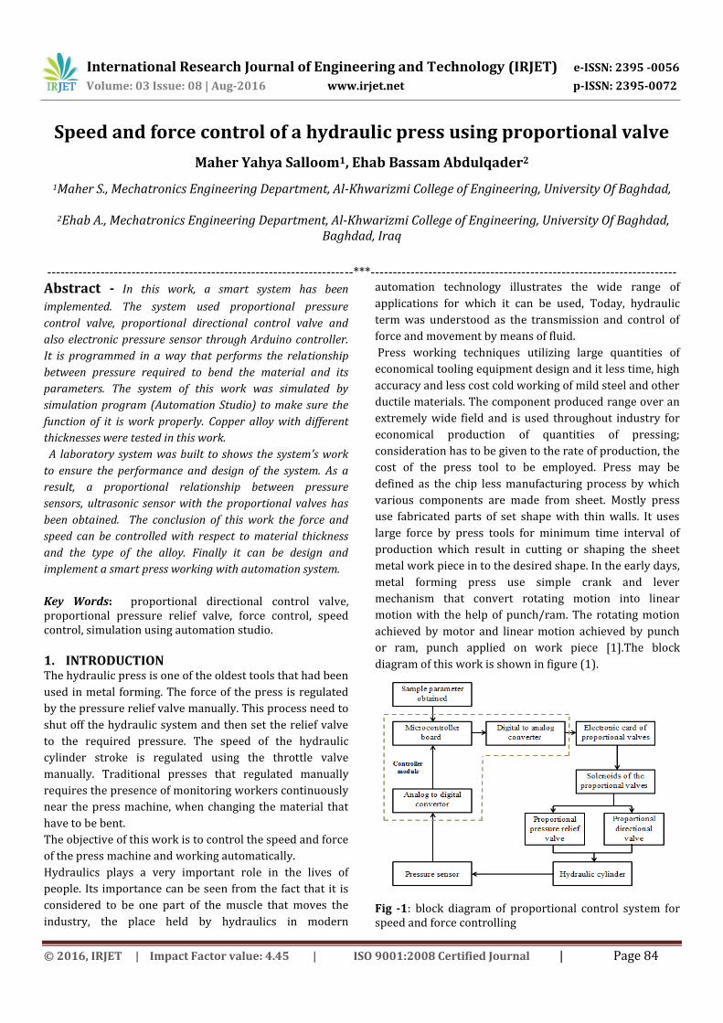
Fig -9 linear speed of hydraulic cylinder with 30% command value
The speed of hydraulic cylinder is increased when increasing the pressure of the system. It is seems from figures (5.1), (5.2) and (5.3) when the command value of the directional proportional control valve change. The difference of the speed increased due to changing the pressure of the system. The increasing of the command value means increasing in flow of the fluid.
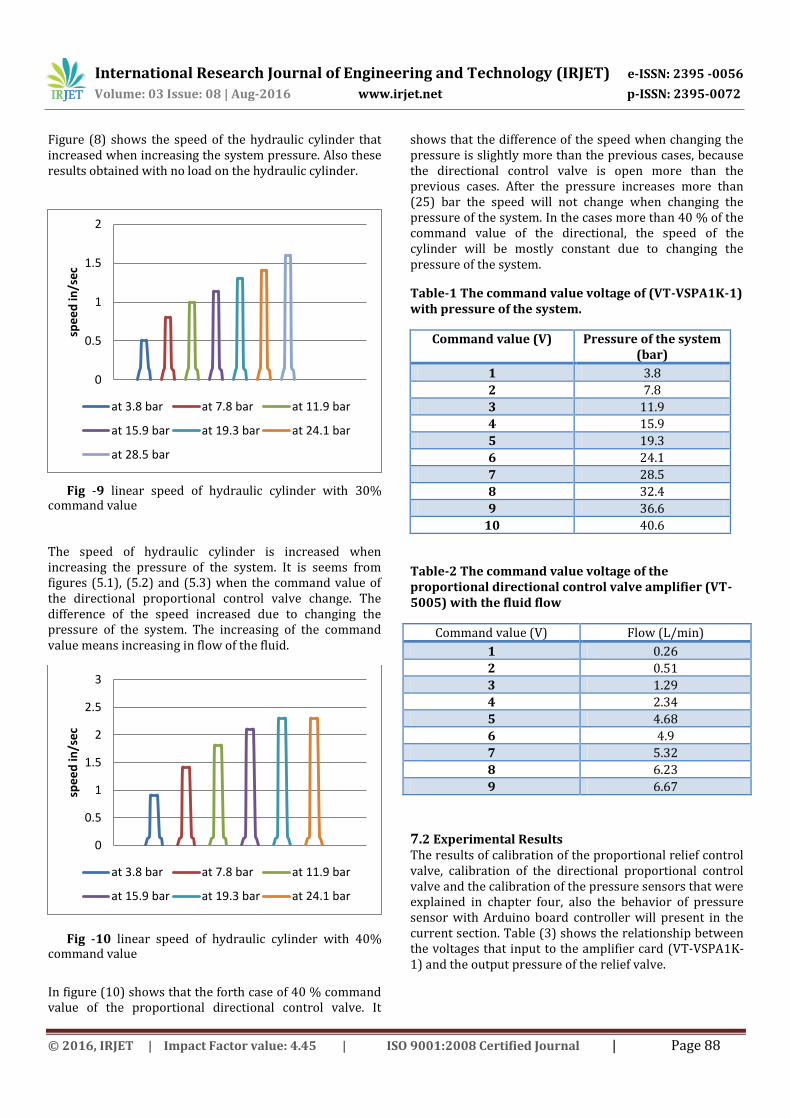
Fig -10 linear speed of hydraulic cylinder with 40%
command value
In figure (10) shows that the forth case of 40 % command value of the proportional directional control valve. It
shows that the difference of the speed when changing the pressure is slightly more than the previous cases, because the directional control valve is open more than the previous cases. After the pressure increases more than (25) bar the speed will not change when changing the pressure of the system. In the cases more than 40 % of the command value of the directional, the speed of the cylinder will be mostly constant due to changing the pressure of the system.
Table-1 The command value voltage of (VT-VSPA1K-1) with pressure of the system.
Command value (V) Pressure of the system (bar)
1 3.8
2 7.8
3 11.9
4 15.9
5 19.3
6 24.1
7 28.5
8 32.4
9 36.6
10 40.6
Table-2 The command value voltage of the proportional directional control valve amplifier (VT-5005) with the fluid flow
Command value (V) Flow (L/min)
1 0.26
2 0.51
3 1.29
4 2.34
5 4.68
6 4.9
7 5.32
8 6.23
9 6.67
7.2 Experimental Results The results of calibration of the proportional relief control valve, calibration of the directional proportional control valve and the calibration of the pressure sensors that were explained in chapter four, also the behavior of pressure sensor with Arduino board controller will present in the current section. Table (3) shows the relationship between the voltages that input to the amplifier card (VT-VSPA1K-1) and the output pressure of the relief valve.
0
0.5
1
1.5
2
spe
ed
in/s
ec
at 3.8 bar at 7.8 bar at 11.9 bar
at 15.9 bar at 19.3 bar at 24.1 bar
at 28.5 bar
0
0.5
1
1.5
2
2.5
3
spe
ed
in/s
ec
at 3.8 bar at 7.8 bar at 11.9 bar
at 15.9 bar at 19.3 bar at 24.1 bar
International Research Journal of Engineering and Technology (IRJET) e-ISSN: 2395 -0056
The behavior of the directional proportional control valve is represented in table (4). The applied voltages on the command value of the amplifier card (VT-5005) is adjusted using internal potentiometers, which built in the card and then select the required voltage to supply the command value of the card. The amount of the fluid flow is depending on this voltage. The command voltage selected as (2.5, 5, 7.5, 9) volt. Table-4 proportional directional control valve
behavior
Voltage (V) Flow (L/min) Cylinder speed (cm/sec)
2.5 2 1.352
5 3 1.783
7.5 4.5 3.183
9 6 4.045
The experimental results were collected from the test rig using two pressure sensors and ultrasonic sensor. These results are shown in table (5) for copper alloy. Table-5 bending force for copper alloy
Real thickness (mm)
Measured
thickness (mm)
Input voltage (V)
Pressure
sensor reading
System pressure (bar)
Bending force
(N)
2 2.2 0.9 70 2.7 520.65
3 3.34 1.104 127 5.8 1176.46
5 5.17 3.857 329 15.8 2908.77
Figures (11), (12) and (13) showing the system pressure behavior while bending copper alloy 2 mm, 3mm and
5mm in thickness respectively, with 25 mm width, and the ultimate tensile strength equal to 275 MPa.
Fig-11 system pressure behavior while bending copper alloy 2 mm thickness
Fig-12 system pressure behavior while bending copper alloy 3 mm thickness
Fig-13 system pressure behavior while bending copper alloy 5 mm thickness
0
2
4
6
8
10
12
0 50 100 150 200 250
pre
ssu
re (
bar
)
time (ms)
0
2
4
6
8
10
12
14
16
18
0 50 100 150 200 250
pre
ssu
re (
bar
)
time (ms)
0
5
10
15
20
25
30
35
40
0 50 100 150 200 250
pre
ssu
re (
bar
)
time (ms)
Region 1
Region 2
Region 3
International Research Journal of Engineering and Technology (IRJET) e-ISSN: 2395 -0056
As shown in these figures the behavior of the system during bending for each material with different thicknesses is presented. The bending is done with three region of force. First region is the free zone which the punch moving in air before reaching the sample. This region should have minimum pressure applied on the system and maximum speed. The second region is the bending region which starts when the punch reached the sample the pressure of this region. The pressure of the system is chosen by the system controller depending on the algorithm of the system. Also the speed of this region is selected depending on the type of material. The last region of the operation is start when the punch reached to the final position. In this region the punch returns back with minimum pressure of the system and with maximum stroke speed. The feedback of the system to the controller is the pressure sensor which gives the controller signals to determine the punch position to know in which region it reach and there for controlling the force and speed of the system. The behavior of the stroke speed of the system during bending is shown in figure (14). The figure shows the behavior of the stroke speed with three regions. First region of maximum speed and the second region represent the bending region of speed 0.3 cm/sec. The third region represents maximum speed with opposite flow direction to let the cylinder to return back.
Fig-14 press stroke speed of the system during bending
8. CONCLUSIONS As a result of this study, the following conclusions are made:
1) The bending force for each material had been determined by the test rig, so that the system will generate the required force for the sample. Un like the other traditional system of fixed applied force, which these systems works under high pressure for each samples and that is lead to losses in power, reduce the life span of the equipment in the system and more noise generated due to high pressure.
2) Automation studio program software can be used to design and simulate the hydraulic system to study the system behavior before building the hydraulic circuit.
3) The bending force required for each sample is determined by the system by using the ultrasonic sensor to determine the sample parameter and then selected the material type, now the force is determined by the controller, then by using the equations of the proportional pressure relief valve which obtained from the calibration of the valve with the amplifier card, and then converting the output of the controller from digital signal to analog signal by the mean of PWM in the Arduino controller, the controller calculate the required voltage to the proportional amplifier to limit the system pressure at a required value.
4) The speed of cylinder stroke while bending is determined by making test of cracks for many samples that had been bent under different speeds, and then chose the optimum speed depending on the number and size of the cracks in each sample.
ACKNOWLEDGEMENT
Our thanks to Mechatronics engineering Department / Al-
Khwarizmi College of Engineering University of Baghdad
for supporting this work .
REFERENCES
[1] Abhijeet S Khandekar, 2015. "Conventional Design
Calculation &3D Modeling of Metal Forming Heavy duty Hydraulic Press". In Int. Journal of Engineering Research and Applications ISSN : 2248-9622, Vol. 5, Issue 6, ( Part - 5) June 2015, pp.100-103.
[2] B. Parthiban, P.Eazhumali, S.Karthi, P.Kalimuthu, 2014. " Design and analysis of C type hydraulic press structure and cylinder". In Internationa journal of research in aeronutical and mechanical engineering ISSN (ONLINE): 2321-3051
[3] Hong-Ming Chen, Guo-Wei Yangand Chong-Cyuan Liao, 2014. "Precision Force Control for an Electro-Hydraulic Press Machine ". In Smart Science Vol. 2, No. 3, pp. 132-138(2014).
[4] RE 30 111/10.10 Rexroth, Bosch Comp user manual.
[5] RE 30095/05.02Rexroth, Bosch Comp user manual.
[6] Automation Studio (AS) user manual (2008) ''Automation Studio circuit design simulation software'', Fluid Power and Automation Technologies, http://www.Automation
[7] Mao-Hsiung Chiang, Chung-Chieh Chen , Chung-Feng Jeffrey Kuo, 2008. "The high response and high efficiency velocity controlof a hydraulic injection molding machine using a variable rotational speed electro-hydraulic pump-controlled system". In Int J Adv Manuf Technol (2009) 43:841–851. DOI 10.1007/s00170-008-1759-z.
[8] Mikell P. Groover , 2007 , " Fundamentals of modern manufacturing materials, processes and systems 3rd edition.". printed in united state of America.
[9] Al-Farajie, M., 2004. "Theoretical and Experimental Investigation of Proportional Directional Control Valve Performance Using Neural Network." Ph.D Thesis, Mechanical Engineering, Al- Mustansiriyah University