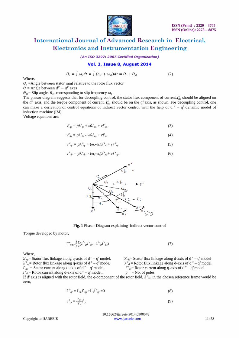
ISSN (Print) : 2320 – 3765 ISSN (Online): 2278 – 8875 International Journal of Advanced Research in Electrical, Electronics and Instrumentation Engineering (An ISO 3297: 2007 Certified Organization) Vol. 3, Issue 8, August 2014 10.15662/ijareeie.2014.0308078 Copyright to IJAREEIE www.ijareeie.com 11457 Speed Control of Induction Motor Fed from Wind Turbine Using Genetic Algorithm Vineet Kumar Tiwari 1 , Satyam Prakash 2 , Abdul Zeeshan 3 PG Student [PE&D], Dept. of Electrical Engineering, United College of Engineering & Research, Allahabad, India 1 . Assistant Professor, Dept. of Electrical Engineering, United College Of Engineering & Research, Allahabad, India. 2&3 ABSTRACT: This paper proposes a design of a speed control of three phase induction motor fed from wind turbine using genetic algorithm. The wind turbine acts as a prime-mover for doubly fed induction generator. To make the system stable, proper monitoring is required or sometimes an auxiliary system can also be a good option, which can support the primary system during undesirable conditions. The three phase induction motor has wide applications in industries due to its rugged construction, efficiency and low cost. Genetic algorithm is used for estimation of feedback controller parameters for three phase induction motor fed from wind turbine .Genetic algorithm offers certain advantages such as simple computational steps, derivative free optimization, reduced no. of iteration and assured near global optima. The simulation results show a significant enhancement in shortening development time and improving dynamic performance of the induction machine compared to the conventional speed control of induction motor drive. KEYWORDS: Wind turbine, doubly fed induction generator, Genetic algorithm & three phase Induction motor. I.INTRODUCTION This study proposes the genetic algorithm for optimal designing of fuzzy controller for speed control of Induction motor fed by wind turbine, which has a simple structure and robust performance in a wide range of operating conditions. The use of induction motors has increased tremendously since the day of its invention. The reason for its day by day increasing popularity can be primarily attributed to its robust construction, simplicity in design and cost effectiveness. These have also proved to be more reliable than DC motors. However, the highly non-linear nature of the induction motor control dynamics demands strenuous control algorithms for the control of speed. The conventional controller types that are used for the aforementioned purpose may be numeric, neural or fuzzy. The controller types that are regularly used are: Proportional Integral (PI), Proportional Derivative (PD), Proportional Integral Derivative (PID), Fuzzy Logic Controller (FLC) or a blend between them. Intelligent control methodologies are being applied to robotics and automation, communications, manufacturing, traffic control, to mention but a few application areas. The design problem of the proposed controller is formulated as an optimization problem and genetic algorithm is employed to search for optimal controller parameters. By minimizing the time domain objective function, in which the deviations in error between the reference and actual speed is involved, speed control of Induction motor is improved. II.INDIRECT FIELD ORIENTED CONTROL (IFOC) Indirect vector control is very popular in industrial applications. The − (direct and quadrature) axes are fixed on the stator, but the − axes, which are fixed on the rotor, are moving at speed . Synchronously rotating axes − are rotating ahead of the − axes by the positive slip angle corresponding to slip frequency. Since the rotor pole is directed on the axis and synchronously rotating axes speed, = +, (1) One can write
Transcript
ISSN (Print) : 2320 – 3765
ISSN (Online): 2278 – 8875
International Journal of Advanced Research in Electrical,
Electronics and Instrumentation Engineering
(An ISO 3297: 2007 Certified Organization)
Vol. 3, Issue 8, August 2014
10.15662/ijareeie.2014.0308078
Copyright to IJAREEIE www.ijareeie.com 11457
Speed Control of Induction Motor Fed from
Wind Turbine Using Genetic Algorithm
Vineet Kumar Tiwari1, Satyam Prakash
2, Abdul Zeeshan
3
PG Student [PE&D], Dept. of Electrical Engineering, United College of Engineering & Research, Allahabad, India1.
Assistant Professor, Dept. of Electrical Engineering, United College Of Engineering & Research, Allahabad, India.2&3
ABSTRACT: This paper proposes a design of a speed control of three phase induction motor fed from wind turbine
using genetic algorithm. The wind turbine acts as a prime-mover for doubly fed induction generator. To make the
system stable, proper monitoring is required or sometimes an auxiliary system can also be a good option, which can
support the primary system during undesirable conditions. The three phase induction motor has wide applications in
industries due to its rugged construction, efficiency and low cost. Genetic algorithm is used for estimation of feedback
controller parameters for three phase induction motor fed from wind turbine .Genetic algorithm offers certain
advantages such as simple computational steps, derivative free optimization, reduced no. of iteration and assured near
global optima. The simulation results show a significant enhancement in shortening development time and improving
dynamic performance of the induction machine compared to the conventional speed control of induction motor drive.
International Journal of Advanced Research in Electrical,
Electronics and Instrumentation Engineering
(An ISO 3297: 2007 Certified Organization)
Vol. 3, Issue 8, August 2014
10.15662/ijareeie.2014.0308078
Copyright to IJAREEIE www.ijareeie.com 11465
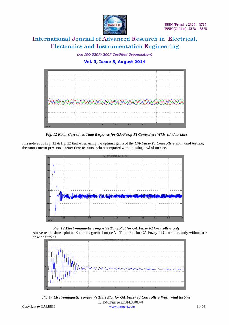
Fig. 13 & fig. 14 show that when using the optimal gains of the GA-Fuzzy PI Controllers with wind turbine, the
Electromagnetic Torque Vs Time Plot presents a better time response when compared a system without using a wind
turbine.
VII. CONCLUSION
By minimizing the time domain objective function, in which the difference between the reference and actual speed are
involved; speed control of IM motor is improved. Simulation results emphasis that the designed GA tuning fuzzy- PI
controller is robust in its operation and gives a superb performance for the change in load.
In this paper, the advantages of the GA-Fuzzy-PI Controller with wind turbine used in the simulation are as follows:
1. The Rise Time is reduced by 98%
2. The Settling Time is reduced by 78.5%
3. The Maximum Overshoot was reduced by 68.5%
The above results clearly indicates that a three phase induction motor fed from wind turbine using Genetic Algorithm
based tuning of the Fuzzy-PI controller gives improved electromagnetic torque, rotor current & better speed
performance which results a robust controlled system. The controller helps the induction motor to track speeds both
above and below its base speed.
REFERENCES
[1] Mishra Amit and Zaheeruddin “Design of Speed Controller for Squirrel-cage Induction Motor using Fuzzy logic based Techniques”
International Journal of Computer Applications (0975 -8887) Volume 58 - No. 22, November 2012
[2] Ouiguini R., Djeffal K., Oussedik A. and Megartsi R., “Speed Control of an Induction Motor using the Fuzzy logic approach.”, ISIE’97 - Guimariies, Portugal, IEEE Catalog Number: 97TH8280, vol.3, pg. 1168 – 1172.
[3] Dr. Rami A. Mahir, Dr. Ahmed Ziad M., Mr. Amjad J. H. “Indirect Field Orientation Control of Induction Machine with Detuning Effect”,
Eng.&Tech..Vol.26.No 1,2008. [4] Pavol Fedor and Daniela Perduková, “A Simple Fuzzy Controller Structure,” Acta Electrotechnica et Informatica No. 4, Vol. 5, pp. 1-4, 2005.
[5] Abdullah I. Al-Odienat, Ayman A. Al-Lawama, “The Advantages of PID Fuzzy Controllers Over The Conventional Types,” American Journal
of Applied Sciences 5 (6): 653-658, 2008, ISSN 1546-9239, pp. 653 – 658. [6] Brian Heber,LongyaXu, Yifan Tang “Fuzzy Logic Enhanced Speed Control of an Indirect Field Oriented Induction Machine Drive” IEEE.
[7] Pengfei Guo Xuezhi Wang Yingshi Han “The Enhanced Genetic Algorithms for the Optimization Design” 978-1-4244-6498-2
[8] João P. A. Vieira, Marcus V. A. Nunes and Ubiratan H. Bezerra “Using Genetic Algorithm to Obtain Optimal Controllers for the DFIG Converters to EnhancePower System Operational Security” ISBN: 978-953-307-221-0.
[9] Babypriya B., Devarajan N. “Simulation and Analysis of a DFIG Wind Energy Conversion System with Genetic Fuzzy Controller”
International Journal of Soft Computing and Engineering (IJSCE) ISSN: 2231-2307, Volume-2, Issue-2, May 2012.