22
Spent Fuel Reprocessing Robert Jubin Oak Ridge National Laboratory

Spent Fuel Reprocessing
Robert Jubin Oak Ridge National Laboratory

Reprocessing of used nuclear fuel is undertaken for several reasons. These include (1) recovery of the valuable fissile constituents (primarily 235U and plutonium) for subsequent reuse in recycle fuel; (2) reduction in the volume of high-level waste (HLW) that must be placed in a geologic repository; and (3) recovery of special isotopes. There are two broad approaches to reprocessing: aqueous and electrochemical. This portion of the course will only address the aqueous methods. Aqueous reprocessing involves the application of mechanical and chemical processing steps to separate, recover, purify, and convert the constituents in the used fuel for subsequent use or disposal. Other major support systems include chemical recycle and waste handling (solid, HLW, low-level liquid waste (LLLW), and gaseous waste). The primary steps are shown in Figure 1.
Figure 1. Aqueous Reprocessing Block Diagram.

Head-End Processes Mechanical Preparations The head end of a reprocessing plant is mechanically intensive. Fuel assemblies weighing ~0.5 MT must be moved from a storage facility, may undergo some degree of disassembly, and then be sheared or chopped and/or de-clad. The typical head-end process is shown in Figure 2. In the case of light water reactor (LWR) fuel assemblies, the end sections are removed and disposed of as waste. The fuel bundle containing the individual fuel pins can be further disassembled or sheared whole into segments that are suitable for subsequent processing. During shearing, some fraction of the radioactive gases and non-radioactive decay product gases will be released into the off-gas systems, which are designed to recover these and other emissions to meet regulatory release limits.
Figure 2. Block Flow Diagram for Aqueous Head-End Processing. Fast reactor fuel is treated in a similar manner with a few additional complications. These include the need to (1) address any residual sodium coolant adhering to the fuel bundle and (2) potentially remove the metal shroud from the fuel bundle. The fuel is typically cut into segments that are 1 to 2 inches in length using a hydraulically activated shear. Key aspects of any shear design include remote maintenance considerations, control of particulates, off-gas capture, and ensuring that the shearing action does not result in crimping of the segments which would prevent the fuel “meat” from being fully exposed to the reactive gases in voloxidation or the nitric acid in dissolution/leaching process steps. To address this latter point, a number of blade designs have been evaluated. Figure 3 shows one such shear blade design with a zigzag blade similar to a pinking shear.

Figure 3. Typical Fuel Shear Blade Design (Croff, 1997).
Voloxidation Voloxidation is a dry head-end process that has been proposed for oxidation of spent fuel oxide and the removal of tritium from fuel prior to aqueous processing (Spencer, 2006). If effective, this process would avoid introducing tritium into the aqueous systems where it would accumulate and greatly complicate the separation, recovery, and packaging of tritium, should this be required to meet regulatory emission requirements. Spent LWR fuel consists of about 94% UO2, with the remainder composed of fission product oxides, transmutation (or transuranium) products, and activation product oxides. Thus, oxidation behavior is almost entirely determined by the uranium component. During voloxidation, the UO2 reacts with oxygen via reaction (1) to form U3O8, causing an expansion of the crystalline structure and resulting in the formation of a relatively fine powder:
3UO2 + O2 U3O8 . (1) The voloxidation process usually takes place at 450°C to 650°C. Higher temperatures increase the reaction rate. The rate of reaction at 480°C is such that >99.9% of the tritium is released in about 3 to 4 h (Goode and Stacy, 1978; Goode et al., 1980). Over 99% of the fuel particles are typically reduced to <44 µm. Tritium is released from the fuel matrix and diffuses to the surface of the particles where it reacts with oxygen to form tritiated water, which then enters the off-gas stream. Off-gases from the voloxidizer usually flow through a “catalytic combiner” to ensure that all released tritium is converted to tritiated water (Spencer, 2006). In the standard process, minor but radiologically significant fractions of other volatile radionuclides are released. This includes ~ 50% of the carbon (14C); 1% of the iodine (129I); and 5% of the krypton (85Kr). (Note: the isotopes shown in parentheses are the isotopes of primary concern for fuel cooled greater than 5 years.) It is known that iodine is chemically bonded with cesium and oxides of uranium and is the reason it is not completely released in standard voloxidation. The evolution of semivolatiles at 480°C includes less than about 0.2% of the 106Ru, 125Sb, and 134–137Cs. Trace amounts of tellurium and selenium would also be expected to volatilize. Higher temperatures increase the fraction of volatiles and semivolatiles evolved (Spencer, 2006)

The reduction in particle size by voloxidation greatly accelerates the rate of the subsequent dissolution process. The higher oxidation state of the uranium reduces the nitric acid requirement and reduces the amount of NOx evolved. Standard voloxidation at 480°C generally increases the insolubility of Ru, Rh, Pd, Mo, and Tc, while the solubility of PuO2 is generally unchanged (Spencer, 2006; Goode, et al., 1980). However, higher voloxidation temperatures can cause sintering of the plutonium and slightly increase the insoluble fraction, which may only be significant for mixed oxide (MOX) fuels. Advanced voloxidation methods are under development using higher operating temperatures and oxidants other than oxygen to remove other fission products (Del Cul et al., 2006; Del Cul, Spencer, and Collins, 2006). Repeated cycling between UO2 and U3O8 using air at ~500°C and H2 at ~800°C enhances the release of fission products [e.g., the Oxidation Reduction Oxidation (OREOX) process under development in Korea] by breaking the particles. Tests at ORNL show that black U3O8 (prepared by voloxidation of UO2 at 500°C) readily reacts with ozone to form a red-colored monoclinic UO3 at temperatures below 200°C that decomposes back to U3O8 at temperatures above 300°C (Del Cul, 2008).
Dissolution The primary purpose of dissolution in an aqueous process is to convert the solid fuel “meat” into an aqueous chemical form suitable for subsequent separation steps. During the dissolution operation, which can either be a batch or continuous process, the fuel is typically reacted with nitric acid to solubilize the uranium, plutonium, minor actinides, and most of the fission products. This completes the separation of the fuel from the cladding and results in the release of certain fission products to the off-gas system. Depending on the fuel burn-up and previous head-end processing, some fraction of the fuel remains as undissolved solids. The key reactions are shown as follows. For uranium metal:
U + 5.5HNO3 UO2 (NO3)2 + 2.25NO2 + 1.25NO + 2.75H2O. (2) The addition of O2 to the dissolver leads to what is referred to as “fumeless dissolution” (Long, 1967), which avoids the formation of NOx gases:
U + 2HNO3 + 1.5O2 UO2 (NO3)2 + H2O. (3) Similar reactions can be written for the direct dissolution of the uranium oxide fuel pellets (not showing the dissolution of the remaining actinides and fission products):
3UO2 + 8HNO3 3UO2 (NO3) 2 + 2NO + 4H2O (4) and
UO2 + 4HNO3 UO2 (NO3) 2 + 2NO2 + 2H2O. (5) While both reactions (4) and (5) occur, reaction (4) tends to dominate when the nitric acid concentration is below 10 M (Benedict, Pigford, and Levi, 1981). In like manner to that of the dissolution of metal [reaction (3)], the addition of O2 during the dissolution of the oxide limits the formation of nitric oxides:

2UO2 + 4HNO3 + O2 2UO2 (NO3)2 + 2H2O. (6)
If the fuel has undergone “standard” voloxidation and the uranium is oxidized to U3O8, then the dissolution reactions are approximated by adding reaction (4) + reaction (5) + eight times reaction (9) to yield (Lewis, 2008)
U3O8 + 7HNO3 3UO2 (NO3)2 + 0.5NO2 + 0.5NO + 3.5H2O (7) or by the approximate equation
U3O8 + 7.35HNO3 3UO2 (NO3)2 + NO2 + 0.35NO + 3.65H2O. (8) And if the uranium source is fully oxidized uranium from advanced voloxidation, one again has a “fumeless dissolution” reaction:
UO3 + 2HNO3 UO2 (NO3)2 + H2O. (9) In batch dissolution, the sheared fuel is placed in a perforated metal basket that is immersed in hot nitric acid to dissolve about 99% of the fuel meat (Croff, 1997). At the end of the dissolution period, only the hulls segments will remain in the basket. A small portion of the fuel that is insoluble (e.g., noble metals such as palladium) will typically fall to the bottom of the dissolver vessel where it is either recovered for subsequent treatment or disposed of as a waste. While most operating reprocessing plants use batch dissolution, there has been and continues to be considerable interest in continuous dissolution. Several designs have been developed and deployed. In a “ferris wheel” design, the fuel segments are placed in baskets located around a large wheel. As the wheel is rotated, the baskets are submerged in heated nitric acid. The rotation rate is set to provide sufficient immersion time for the fuel meat to dissolve. As the wheel continues its rotation, the empty hulls are dumped into a collection hopper for metal waste. The basket is then loaded with more fuel segments to repeat the process (Croff, 1997). The most recent installation of such a dissolver is at the Rokkasho Reprocessing Plant in Japan. A horizontal dissolver design has been developed and cold tested at ORNL. In this design, the fuel segments are fed into one end of a rotating, nearly horizontal cylinder and forced along its length by its internal structure (e.g., a helix). The rotating actions are of two types; the first is an action that moves the fuel from one stage or segment of the dissolver to the next, and the second is a rocking action to aid the dissolution. Nitric acid enters the other end and moves countercurrent to the fuel/cladding. During this countercurrent movement, the acid contacts and dissolves the fuel material. The countercurrent movement of the acid and cladding also ensures that the more difficult fuel particles see the strongest acid and provides a degree of washing of the hulls in fresh acid. In all cases the dissolver must be designed to prevent criticality (typically by virtue of its geometry) and operate while in contact with highly corrosive reagents.
Separation Processes There are two primary separation processes used in aqueous fuel reprocessing: solvent extraction and ion exchange.
Solvent Extraction Solvent extraction (SX) is the workhorse for industrial-scale separations in fuel reprocessing. Solvent extraction is a very flexible process that is easily adapted to multistage operations. This is highly desirable when very high purification is needed or when the properties of materials to be recovered are so similar that single-stage precipitation or crystallization would not result in acceptable separations (Benedict et al., 1981). Ion exchange, which will be discussed later, can also be used to achieve high degrees of separation but is generally most suited for situations where small quantities or low concentrations are involved. Solvent extraction involves bringing two immiscible phases into intimate contact, typically an aqueous phase and an organic phase. When this occurs, the extractable components will distribute between the two phases. Assuming sufficient contact time, equilibrium will be established between the two phases. The ratio of the concentration in the resulting phases is referred to as the distribution coefficient, D.
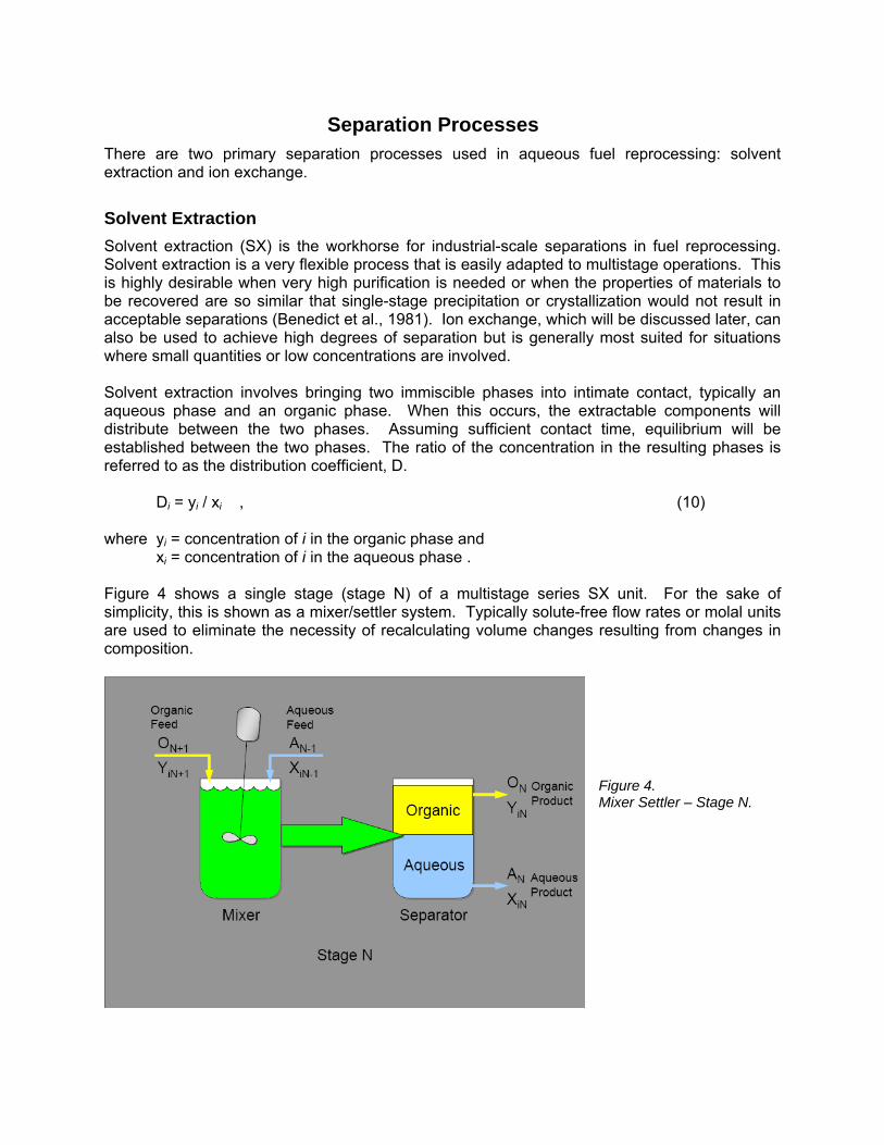
Di = yi / xi , (10) where yi = concentration of i in the organic phase and xi = concentration of i in the aqueous phase . Figure 4 shows a single stage (stage N) of a multistage series SX unit. For the sake of simplicity, this is shown as a mixer/settler system. Typically solute-free flow rates or molal units are used to eliminate the necessity of recalculating volume changes resulting from changes in composition.
Figure 4. Mixer Settler – Stage N.
For a simple one-stage batch extraction based on Figure 4, one can write the following material balance assuming that the extractable component is initially only in the aqueous feed:
O(yn+1) + A(xn-1) = O(yn) + A(xn) , (11) where O = organic volume and
A = aqueous volume. Assuming yn+1 = 0 and D = yn/xn yields the following:
yn = D(xn-1) / (OD/A + 1). (12) The fraction extracted is
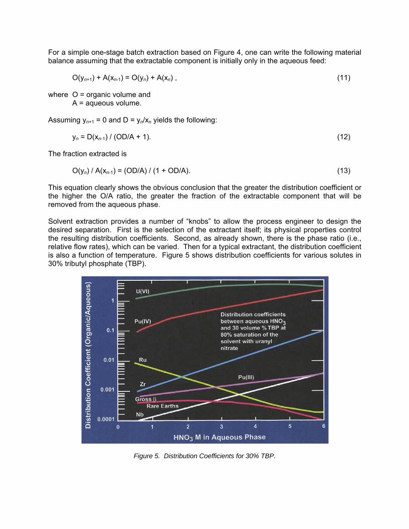
O(yn) / A(xn-1) = (OD/A) / (1 + OD/A). (13) This equation clearly shows the obvious conclusion that the greater the distribution coefficient or the higher the O/A ratio, the greater the fraction of the extractable component that will be removed from the aqueous phase. Solvent extraction provides a number of “knobs” to allow the process engineer to design the desired separation. First is the selection of the extractant itself; its physical properties control the resulting distribution coefficients. Second, as already shown, there is the phase ratio (i.e., relative flow rates), which can be varied. Then for a typical extractant, the distribution coefficient is also a function of temperature. Figure 5 shows distribution coefficients for various solutes in 30% tributyl phosphate (TBP).
Figure 5. Distribution Coefficients for 30% TBP.

Note the strong impact of nitric acid concentration on the various distribution coefficients in Figure 5. This figure also shows the significant impact that valence state has on the extractability of metals such as plutonium. While Pu4+ is highly extractable at high acid conditions, Pu3+ is virtually impossible to extract. What is not shown clearly in this figure is that the distribution coefficients are also impacted by the interaction of the solutes present as well as the impact that temperature has on the distribution coefficients. Solvent extraction in most fuel cycle applications is performed in multiple stages to effect the desired separations. This is accomplished by coupling multiple contactors in series or banks such that the aqueous and organic flows are countercurrent (Figure 6).
Figure 6. Multistage Countercurrent SX Bank. One of the most widely used solvent extraction processes in fuel reprocessing is the PUREX (Plutonium - URanium EXtraction) process. The PUREX process dates back to 1949 when it was discovered that tetravalent cerium nitrate could be separated from trivalent rare earths using TBP (Benedict et al., 1981). Based on this discovery, process development and demonstration work was conducted at Knolls Atomic Power Laboratory and ORNL prior to deployment in the plutonium production plant at the Savannah River Site in 1954 and then at the Hanford site in Washington State. Since that time it has been used in all commercial reprocessing plants. The SX cycle is defined for the PUREX process as “those operations in which separations are achieved by transferring the U and/or Pu from the aqueous phase to the organic phase and then recovering the U and/or Pu by back-extraction into an aqueous phase” (Wymer and Vondra, 1981). In the PUREX process, the aqueous phase is the adjusted dissolver product and the organic extractant is typically a 30% TBP in a purified kerosene or n-dodecane diluent. Under highly acidic conditions, the uranium and plutonium are extracted into the organic phase. The loaded organic phase is then contacted with dilute acid to strip the uranium and plutonium back into the aqueous phase. Most other constituents of spent fuel prefer the aqueous phase under both conditions. Ordinarily, the plutonium is in the +4 valence state and tends to be extracted with the uranium. If a separation of uranium and plutonium is desired, the Pu4+ can be reduced to the +3 valence state by using suitable chemicals; when in this state, it has a very low distribution coefficient and prefers the aqueous phase. This process is most often conducted in a bank of mixer/settler contactors or in a pulsed column, both of which are configured to provide

countercurrent flow of the two phases and a sufficient number of theoretical stages to effect the desired separation.
Figure 7. Block Flow Diagram for PUREX Process
In the “normal” PUREX flowsheet the U/Pu loaded organic phase is contacted with an aqueous phase containing nitric acid and a reductant (see Figure 7). This results in the Pu3+ transferring to the aqueous phase while the uranium remains in the organic phase. The separated aqueous phase, containing the plutonium, then advances to the plutonium purification cycles where any residual uranium is removed resulting in a pure plutonium stream. For the Barnwell Nuclear Fuel Plant (BNFP) in South Carolina, specifications for the plutonium product were < 100 ppm uranium, less than 40µCi/g Pu total gamma, and <5 µCi/g Pu zirconium-niobium activity. The uranium is then back-extracted as part of the uranium/plutonium partitioning cycle into a clean aqueous phase using dilute nitric acid (Benedict et al., 1981). The resulting uranium stream is further separated from residual fission products in the uranium purification cycle. Multiple cycles can be used to improve product purity. One PUREX cycle typically has an upper limit on its decontamination factor or its ability to decontaminate the uranium or plutonium from the fission products and transplutonium elements of about 1000 (Wymer and Vondra, 1981). Research and development efforts under the DOE Advance Fuel Cycle Initiative (AFCI) have examined a number of SX options that allow a variety of processing options and product stream combinations. Figures 8 and 9 show schematically two sample flow sheets for the separation of uranium, plutonium, and other fuel components. These are of varying complexity but show how combining various SX processes and produce very different products. The goal in the flow sheet shown in Figure 8 is to recover “pure” uranium, americium, and curium streams while never producing pure plutonium. The initial step uses a TBP-based SX process to separate uranium and technetium from the dissolved fuel solution while not extracting the plutonium.
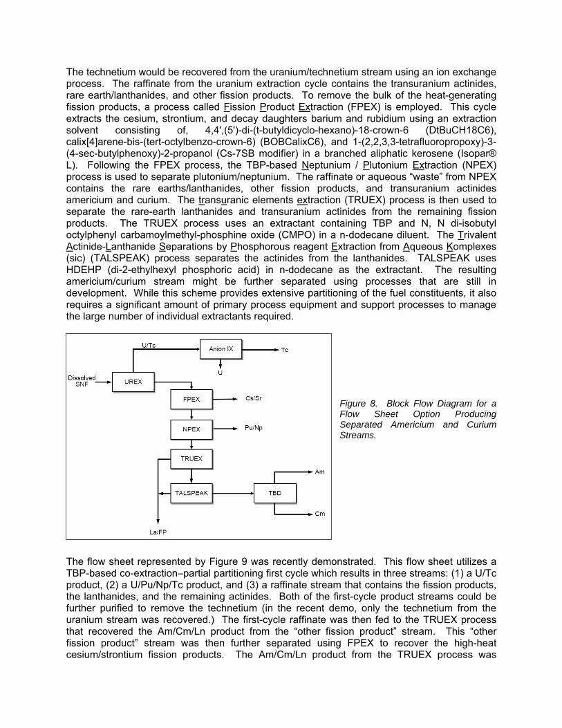
The technetium would be recovered from the uranium/technetium stream using an ion exchange process. The raffinate from the uranium extraction cycle contains the transuranium actinides, rare earth/lanthanides, and other fission products. To remove the bulk of the heat-generating fission products, a process called Fission Product Extraction (FPEX) is employed. This cycle extracts the cesium, strontium, and decay daughters barium and rubidium using an extraction solvent consisting of, 4,4',(5')-di-(t-butyldicyclo-hexano)-18-crown-6 (DtBuCH18C6), calix[4]arene-bis-(tert-octylbenzo-crown-6) (BOBCalixC6), and 1-(2,2,3,3-tetrafluoropropoxy)-3-(4-sec-butylphenoxy)-2-propanol (Cs-7SB modifier) in a branched aliphatic kerosene (Isopar® L). Following the FPEX process, the TBP-based Neptunium / Plutonium Extraction (NPEX) process is used to separate plutonium/neptunium. The raffinate or aqueous “waste” from NPEX contains the rare earths/lanthanides, other fission products, and transuranium actinides americium and curium. The transuranic elements extraction (TRUEX) process is then used to separate the rare-earth lanthanides and transuranium actinides from the remaining fission products. The TRUEX process uses an extractant containing TBP and N, N di-isobutyl octylphenyl carbamoylmethyl-phosphine oxide (CMPO) in a n-dodecane diluent. The Trivalent Actinide-Lanthanide Separations by Phosphorous reagent Extraction from Aqueous Komplexes (sic) (TALSPEAK) process separates the actinides from the lanthanides. TALSPEAK uses HDEHP (di-2-ethylhexyl phosphoric acid) in n-dodecane as the extractant. The resulting americium/curium stream might be further separated using processes that are still in development. While this scheme provides extensive partitioning of the fuel constituents, it also requires a significant amount of primary process equipment and support processes to manage the large number of individual extractants required.
Figure 8. Block Flow Diagram for a Flow Sheet Option Producing Separated Americium and Curium Streams.
The flow sheet represented by Figure 9 was recently demonstrated. This flow sheet utilizes a TBP-based co-extraction–partial partitioning first cycle which results in three streams: (1) a U/Tc product, (2) a U/Pu/Np/Tc product, and (3) a raffinate stream that contains the fission products, the lanthanides, and the remaining actinides. Both of the first-cycle product streams could be further purified to remove the technetium (in the recent demo, only the technetium from the uranium stream was recovered.) The first-cycle raffinate was then fed to the TRUEX process that recovered the Am/Cm/Ln product from the “other fission product” stream. This “other fission product” stream was then further separated using FPEX to recover the high-heat cesium/strontium fission products. The Am/Cm/Ln product from the TRUEX process was
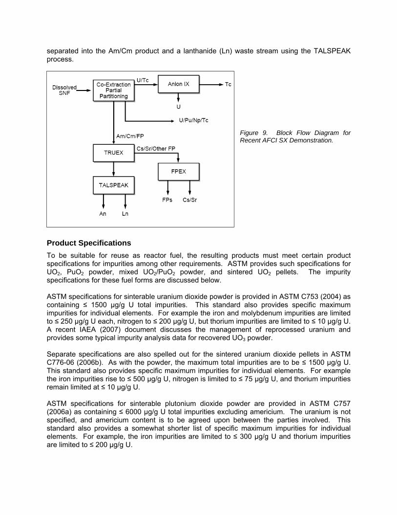
separated into the Am/Cm product and a lanthanide (Ln) waste stream using the TALSPEAK process.
Figure 9. Block Flow Diagram for Recent AFCI SX Demonstration.
Product Specifications To be suitable for reuse as reactor fuel, the resulting products must meet certain product specifications for impurities among other requirements. ASTM provides such specifications for UO2, PuO2 powder, mixed UO2/PuO2 powder, and sintered UO2 pellets. The impurity specifications for these fuel forms are discussed below. ASTM specifications for sinterable uranium dioxide powder is provided in ASTM C753 (2004) as containing ≤ 1500 µg/g U total impurities. This standard also provides specific maximum impurities for individual elements. For example the iron and molybdenum impurities are limited to ≤ 250 µg/g U each, nitrogen to ≤ 200 µg/g U, but thorium impurities are limited to ≤ 10 µg/g U. A recent IAEA (2007) document discusses the management of reprocessed uranium and provides some typical impurity analysis data for recovered UO3 powder. Separate specifications are also spelled out for the sintered uranium dioxide pellets in ASTM C776-06 (2006b). As with the powder, the maximum total impurities are to be ≤ 1500 µg/g U. This standard also provides specific maximum impurities for individual elements. For example the iron impurities rise to ≤ 500 µg/g U, nitrogen is limited to ≤ 75 µg/g U, and thorium impurities remain limited at ≤ 10 µg/g U. ASTM specifications for sinterable plutonium dioxide powder are provided in ASTM C757 (2006a) as containing ≤ 6000 µg/g U total impurities excluding americium. The uranium is not specified, and americium content is to be agreed upon between the parties involved. This standard also provides a somewhat shorter list of specific maximum impurities for individual elements. For example, the iron impurities are limited to ≤ 300 µg/g U and thorium impurities are limited to ≤ 200 µg/g U.

Under the current AFCI thinking where there will be no pure plutonium stream produced, ASTM C1008 (2008) is applicable for fast reactor fuel. This standard provides the impurity specification for sintered MOX pellets. Total impurities are to be ≤ 5000 µg/g (U+Pu) total impurities excluding americium and thorium. Test specifications for LWR MOX pellets were developed as part of the Fissile Materials Disposition Program (Cowell, 1997) and are significantly tighter than the ASTM MOX specification.
Ion Exchange – Organic/Inorganic Ion exchange (IX) is often used to either “polish” the uranium and plutonium product that has been initially separated via SX or for the recovery of specific elements from dilute streams. Hence one is either (1) trying to retain undesired constituents (polishing) on the IX media and the “product” is what passes through the bed or (2) capturing a target constituent on the IX media and later recovering product from the media. There are several variations available to the process designer. The IX material is chosen based on its selectivity for specific constituents. The media are typically solid organic resins, but inorganic materials are also used. For the purposes of illustration, one of the most common uses of IX is that of softening water. This is accomplished using a bed of polymeric beads in which large organic anions are incorporated. The organic anions are paired with sodium cations. As the “hard” water flows through the bed, the calcium and magnesium ions are exchanged from the solution for sodium ions from the bed by the following reactions (King, 1971):
Ca++ + 2Na+ resin- Ca++ (resin)2-- + 2Na+, and (13)
Mg++ + 2Na+ resin- Mg++ (resin)2-- + 2Na+. (14) Other constituents in the solution for which the IX resin is not selective will remain in the aqueous solution and pass through the IX bed. The capacity of IX material is finite and can be defined by the equilibrium constant (K) (King, 1971):
KCa++-Na+ = (Ca++)resin(Na+)2 aqueous /(Ca++)aqueous(Na+)2
resin. (15) Once the K value is exceeded, the bed will cease to remove the constituent of interest. After the material is loaded with the desired product, the IX bed must be regenerated. The inflow of the product-bearing solution is stopped, and a new, clean aqueous stream (called the eluant) is passed through the ion exchange bed. The properties in the eluent are typically opposite those of the initial stream. In the water softening example, the eluent stream is high in sodium and drives the IX reaction in reverse. In fuel reprocessing applications, the product stream from solvent extraction may still contain a level of contaminants such that subsequent use in recycle fuel will be out of specification. This stream may be polished by IX. In the case of the PUREX process, the plutonium product stream from the second plutonium cycle is removed from the aqueous stream by the IX bed while the contaminants remain in the highly acidic aqueous solution. The plutonium is recovered from the IX bed using an eluant stream that will be only slightly acidic. A second example is from the AFCI work is the recovery of the technetium from the uranium stream from the Uranium Extraction (UREX) cycle. Here the very small amount (mass-wise) of technetium

present in the aqueous uranium product stream is recovered from the much larger quantity of uranium using IX.
Product Conversion The product(s) that are recovered from the spent fuel via the SX/purification cycles are typically converted from the nitrate solutions to an oxide form. This can be accomplished by various approaches including direct thermal denitration, Modified Direct Denitration (MDD), or by resin loading/calcination.
Supporting Operations (Separations) Distillation While distillation is the dominate separation process of the petrochemical industry, it plays a secondary role in fuel reprocessing. While this role does not get the attention that the SX processes do, it is critical to the overall plant operation. The fuel comes into the facility as a solid and the products and waste leave the facility as solids, yet all of the separation steps involve liquids, mainly containing nitric acid. Looking back to reactions (4)–(6), one will observe that nitric acid is consumed at the rate of two to four moles per mole of uranium processed. For a 800 MT/yr plant, the quantity of nitric acid required would approach 1,000,000 liters per year. If the acid is not recycled, this amount would require disposal or destruction. Acid vapors are recovered primarily from the dissolver off-gas, product conversion (a denitration process), and waste solidification. Other sources include condensates from evaporation operations to concentrate inter-cycle or intra-cycle streams and product streams. Conventional distillation technology can be used noting remote maintenance requirements as fission products will tend to accumulate in the bottoms or reboiler.
Steam Stripping A little context is needed here that will become apparent shortly. An explosive compound can be formed when an organic material (e.g., TBP) comes in contact with concentrated nitric acid at temperature above 120°C (NRC, 2008). If formed, red oil can explosively decompose if the temperature goes above 130°C. Such explosions have occurred in the United States, Canada, and Russia. Steam stripping can be used to remove trace organics from an aqueous stream. This process uses a steam stream to effect a transfer of organic compounds from the heated aqueous phase to the vapor phase. The process takes place at a temperature close to the boiling point of water. One interesting feature of steam stripping is that typically no off-gas treatment is required. The only waste stream is the recovered concentrated organics. Steam stripping has also been considered for the recovery/separation of the organic diluent for use in “diluent” washing of the aqueous product from the SX cycles. Both approaches (steam stripping directly or diluent washing) address the same problem: eliminate the potential for accumulation of nitrated polymeric material that arises from the carryover of TBP into a plant evaporator. Any aqueous stream that leaves a bank of SX equipment will contain some level of organic material. This includes both the dissolved TBP and some entrained organic phase. The quantity is determined by the physical properties of the materials and by the operating conditions of the equipment. Steam stripping can be used directly to recover the organics from the aqueous phase, but this is a fairly energy-intensive
process. A second approach involves the addition of several solvent extraction stages in which the aqueous phase is contacted with a small stream of the organic phase diluent to recover the dissolved and entrained TBP.
Off-Gas Treatment Off-gas treatment in a fuel reprocessing plant must address three main gaseous streams. The first is the off-gas from the head end which includes the shear, optional voloxidizer, and the dissolver. This collectively is sometime called the Dissolver Off-Gas (DOG). The second is the “vessel off-gas” (VOG), which collects in-leakage to all of the process equipment and the instrument air used in bubblers, air sparge discharge, etc. The third is the cell ventilation, which provides confinement to the process cell. Each of these has unique characteristics and processing challenges.
Regulatory Requirements/Drivers There are several key regulatory drivers that impact volatile gas emissions from a nuclear fuel recycle facility. The United States Environmental Protection Agency (EPA) has established annual individual dose limits for specific organs and for the whole body resulting from nuclear fuel cycle facilities in the commercial sector through 40 CFR 190. Radionuclide-specific release limits in terms of curies released per unit of power produced is also defined in 40 CFR 190.10 (CFR, 2007a). These limits are as follows:
(a) The annual dose equivalent does not exceed 25 millirems to the whole body, 75 millirems to the thyroid, and 25 millirems to any other organ of any member of the public as the result of exposures to planned discharges of radioactive materials, radon and its daughters excepted, to the general environment from uranium fuel cycle operations and to radiation from these operations (b) The total quantity of radioactive materials entering the general environment from the entire uranium fuel cycle, per gigawatt-year of electrical energy produced by the fuel cycle, contains less than 50,000 curies of 85Kr, 5 millicuries of 129I, and 0.5 millicuries combined of 239Pu and other alpha-emitting transuranic radionuclides with half-lives greater than 1 year.
While DOE is not subject to the EPA requirements, future commercial reprocessing facilities will be. Table 1 shows the 10 CFR 20 dose limits to both workers and to the individual members of the public. Section 20.1302 (CFR, 2007b) also provides release limits at the site boundaries for both gaseous and liquid effluents.
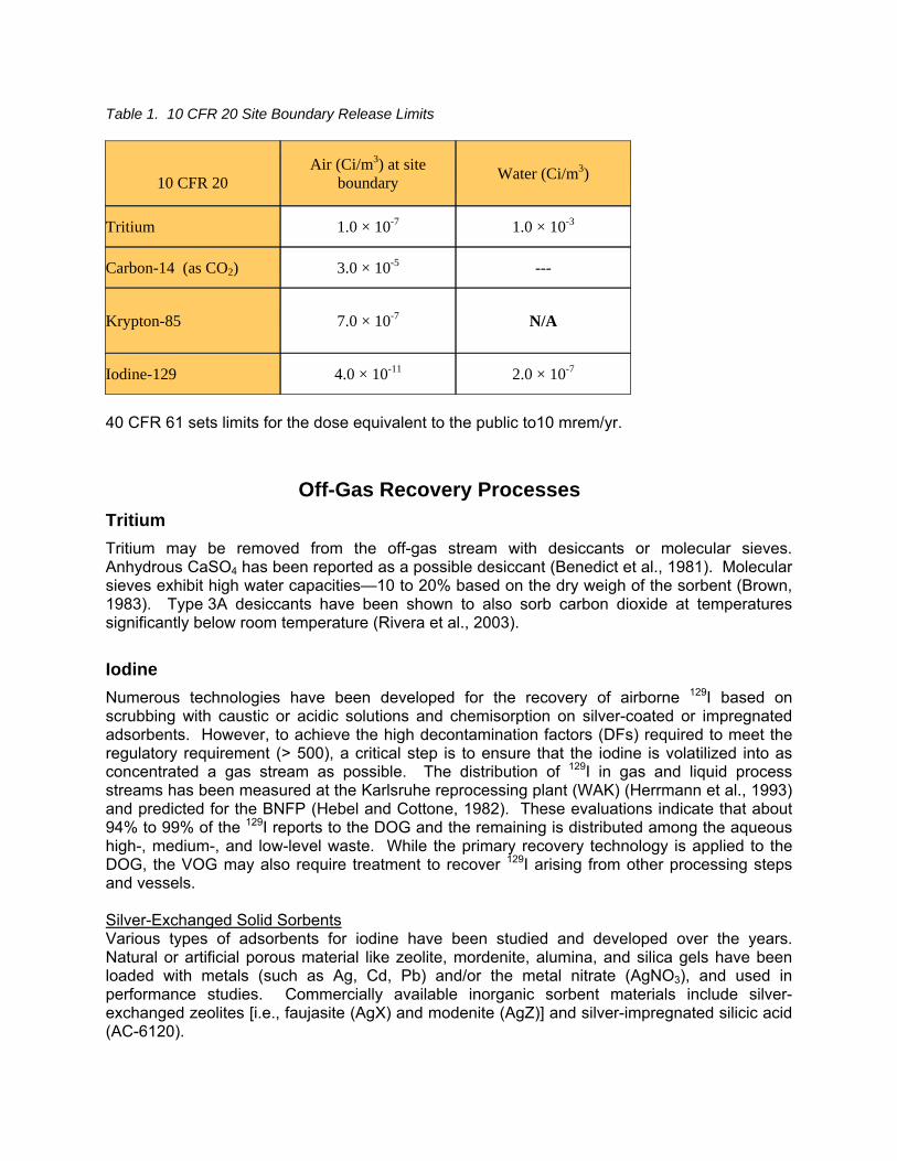
Table 1. 10 CFR 20 Site Boundary Release Limits
10 CFR 20
Air (Ci/m3) at site boundary Water (Ci/m3)
Tritium 1.0 × 10⁻⁷ 1.0 × 10⁻³
Carbon-14 (as CO2) 3.0 × 10⁻⁵ ---
Krypton-85 7.0 × 10⁻⁷ N/A
Iodine-129 4.0 × 10⁻¹¹ 2.0 × 10⁻⁷
40 CFR 61 sets limits for the dose equivalent to the public to10 mrem/yr.
Off-Gas Recovery Processes Tritium Tritium may be removed from the off-gas stream with desiccants or molecular sieves. Anhydrous CaSO4 has been reported as a possible desiccant (Benedict et al., 1981). Molecular sieves exhibit high water capacities—10 to 20% based on the dry weigh of the sorbent (Brown, 1983). Type 3A desiccants have been shown to also sorb carbon dioxide at temperatures significantly below room temperature (Rivera et al., 2003).
Iodine Numerous technologies have been developed for the recovery of airborne 129I based on scrubbing with caustic or acidic solutions and chemisorption on silver-coated or impregnated adsorbents. However, to achieve the high decontamination factors (DFs) required to meet the regulatory requirement (> 500), a critical step is to ensure that the iodine is volatilized into as concentrated a gas stream as possible. The distribution of 129I in gas and liquid process streams has been measured at the Karlsruhe reprocessing plant (WAK) (Herrmann et al., 1993) and predicted for the BNFP (Hebel and Cottone, 1982). These evaluations indicate that about 94% to 99% of the 129I reports to the DOG and the remaining is distributed among the aqueous high-, medium-, and low-level waste. While the primary recovery technology is applied to the DOG, the VOG may also require treatment to recover 129I arising from other processing steps and vessels. Silver-Exchanged Solid Sorbents Various types of adsorbents for iodine have been studied and developed over the years. Natural or artificial porous material like zeolite, mordenite, alumina, and silica gels have been loaded with metals (such as Ag, Cd, Pb) and/or the metal nitrate (AgNO3), and used in performance studies. Commercially available inorganic sorbent materials include silver-exchanged zeolites [i.e., faujasite (AgX) and modenite (AgZ)] and silver-impregnated silicic acid (AC-6120).

The development of silver-exchanged AgX and AgZ was conducted primarily in the United States and has not advanced beyond laboratory tests for 129I recovery. Published literature surveyed by Thomas et al. (1977) indicate iodine loadings ranging from 80 to 200 mg of iodine per gram of AgX or AgZ while maintaining DFs in the range of 100 to 10,000 for elemental iodine. While effective in removing iodine from gas streams, the AgX substrate decomposes in the presence of NOx and water vapor. Therefore a more acid-resistant substrate was desirable for use in the DOG application. The AgZ sorbent has been developed specifically for application in DOG streams because of its high acid resistance. Elemental iodine loadings of 170 mg I2 per gram of AgZ (Staples et al., 1977; Thomas et al., 1978) and typical methyl iodide loadings of 140 to 180 mg CH3I per gram of substrate (Jubin, 1983; Scheele et al., 1983) have been obtained for tests on simulated DOG streams. Liquid Scrubbing Caustic scrubbing for 129I recovery has been applied at the Windscale, Thorp, UP1, UP2, and PNC fuel reprocessing plants (FRPs) (Hebel and Cottone, 1982; IAEA, 1987). The Windscale FRP reports a DF of 50 while the other DFs are not reported. The organic iodides pass through the solution essentially unreacted, and CO2 and NOx deplete the scrubbing solution by forming carbonate and nitrates. The operating experience at the Tokai FRP indicated that while the caustic scrubber in the DOG provides sufficient removal efficiency, that of the VOG scrubber was lower than expected. This was attributed to the formation of iodine-organic compounds in the VOG stream (IAEA, 1987). The THORP plant utilizes a caustic scrubber to achieve an iodine DF of 100. This same caustic scrubber is used to scrub NOx, ruthenium (gas), and 14C with DFs of 100, 100, and 70, respectively. The IODOX (IODine Oxidation) technology was developed for application to liquid-metal fast breeder reactor (LMFBR) fuel reprocessing where the spent fuel would have been processed within 180 days of leaving the reactor and would have required high DFs to control 131I releases (>104). Decontamination factors up to 106 have been obtained in cold engineering tests. The process uses 20–22 M HNO3 in a bubble cap column to recover the iodine as HI3O8 (ERDA, 1976). The Mercurex process was also developed for the treatment of the dissolver off-gas evolved during the processing of very short cooled fuels where very high DFs are required (>105). The process uses a mercuric nitrate – nitric acid solution in a packed or bubble cap column to recover the iodine as HgI2, which is subsequently oxidized to the iodate (Hg(IO3)2. In the Mercurex process, airborne iodine is absorbed in a Hg(NO3)2 – HNO3 solution to form mercury iodate and iodide complexes. Decontamination factors for elemental iodine and methyl iodide of 1000 to 5000 and 100, respectively, have been obtained at temperatures of 50°C. Mecurex has been applied at an industrial scale at the Dounreay and Nuclear Fuel Services FRPs with reported DFs of 150 and 32, respectively (Hebel and Cottone, 1982). Two scrubbers in series were installed in the BNFP. The claimed DFs were 10–75 (IAEA, 1987).
Krypton Most of the 85Kr (>99%) remains in the spent fuel until it is sheared and dissolved. The 85Kr would be primarily released to the DOG in the range of hundreds of parts per million. Recovery processes are based on physical separation from the off-gas since krypton is chemically inert. The primary technologies for 85Kr control are cryogenic distillation, fluorocarbon adsorption, and

sorption on molecular sieves or charcoal. Xenon is also recovered by these processes. The xenon is present at about 10 times the krypton concentration in the gas stream. Cryogenic distillation is a technology to recover rare gases that has been used commercially for many years. The cryogenic distillation process has been successfully used at the Idaho Chemical Processing Plant (ICPP) to recover krypton. This is commercial technology but was not optimized for high krypton recovery DFs. Further development work has been done in Belgium, France, Germany, and Japan on the cryogenic process. Decontamination factors of 100 to 1000 have been reported (Goossens et al., 1991). Fluorocarbon absorption technology has been developed at the Oak Ridge Gaseous Diffusion Plant and at the Karlsruhe, Germany (Little et a1., 1983; IAEA, 1980a; Henrich et al., 1985; Hebel and Cottone, 1983). This process uses an organic solvent (CCl2F2 called R-12) to selectively absorb noble gases from air or DOG streams; the noble gases are then stripped from the solvent by boiling. The basis for this recovery process is the solubility difference that exists between the various gas compounds in the solvent chosen for the process. Krypton recoveries greater than 99% have been demonstrated with concentration factors ranging from 1000 to 10,000. Both activated carbon and zeolites have been studied to recover krypton from the DOG stream. One possible system uses a bed of synthetic silver mordenite (AgZ) at ambient temperatures to recover xenon. The “xenon-free” gas is then chilled and passed onto a second hydrogen mordenite (HZ) operated at ~80°C that absorbs the krypton. Laboratory tests have shown DFs of 400 for krypton and 4000 for xenon (Pence, 1981).
Carbon-14 The bulk of the 14C found in the irradiated nuclear fuel is assumed to be evolved as CO2 into the DOG during fuel dissolution. If standard voloxidation is used, then approximately 50% of the 14C will be released in the voloxidizer. There are a number of technologies that have been developed for CO2 removal. These include caustic scrubbing, molecular sieve adsorption, adsorbent bed fixation, and co-absorbtion/concentration in conjunction with 85Kr recovery followed by fixation. Adsorption of CO2 utilizing a caustic solution in a packed column to form carbonates is a common industrial process (Trevorrow et al., 1983). While the process has never been applied specifically for 14C recovery in the nuclear fuel cycle, the EPA indicated in 1977 that it would be the most probable candidate for application at that time (Brown et al., 1983). The adsorption of CO2 by packed adsorbent beds is also a common industrial process. The 4A molecular sieve has been demonstrated at laboratory scale to removed the CO2 down to the level of detection (10 ppm) from a >90% CO2 stream. The bed is regenerated by heating to 200°C. Pilot-scale studies have been conducted by researchers at Ontario Hydro on a gas solid reaction process to remove 14C using beds of either Ca(OH)2 or Ba(OH)2•8H2O.

Recovery of Semi-Volatile Components and Particulates The head-end portion of the fuel reprocessing plant and the waste processing portion presents additional challenges in terms of the composition of the off-gas streams to be treated. In addition to the gaseous species already discussed, a number of “semi-volatile” species are released to the off-gas stream. These include oxides of Ru, Cs, Tc, Te, and Sb. Of these, the most studied are ruthenium and cesium, which also typically require the highest recovery factors. The amount released is highly dependent on the processing conditions. For example, under normal voloxidation conditions only very limited fractions of krypton, 14C, and iodine are released. Work in the United States and Korea has recently shown that under high temperatures and O2 or O3 oxidizing conditions, virtually all of the 3H, 14C, 85Kr, 129I, 99Tc, Ru, and Cs are released to the off-gas and significant fractions of the Te, Rh, and Mo are also volatilized. Ruthenium is present in the gas phase as RuO4. Sakurai et al. (1985) report that RuO4 may be deposited on metal surfaces at low temperatures. It is hypothesized that the deposition forms weak Ru-O-O-Ru bonds on the metal surfaces. The deposit is easily removed with a 1 N NaOH solution containing 1.5 wt% K2S2O8. If this deposit is heated above 500°C, a large portion is volatilized, but a portion is reduced to elemental ruthenium. At high temperatures ruthenium can also plate out on metal surfaces and is difficult to remove even with strong acids. This results in lower oxides and even the ruthenium metal being formed via an autocatalytic reaction. This can cause line plugging and localized high radiation fields (Goossens, 1991). Volatile ruthenium is easily trapped by physical absorption on silica gel or molecular sieves at low temperatures or on iron oxides at temperatures between 300 and 500°C. Cesium is only volatilized at high temperatures above about 800°C. Data presented by Goossens (1991) shows ~0.8% of cesium is released in 6 hours from borosilicate glass at 800°C. This increases to ~25% at 1000°C. Upon cooling, submicron particles are formed. In addition, the head-end processes may result in the production of very fine particulates which must also be removed prior to the release of the gas stream to the facility stack. Particulate filtration is for the most part a well-established technology [see Goossens (1991) and DOE (2003)]. Typical pleated paper HEPA filters recover 99.99% of 0.3 µm particles and operate at temperature less than 120°C. It is possible to recover 99.99% of particles down to 0.1–0.3 µm range with modest penalty in filter resistance. Specially designed filters can operate at temperatures above 500°C.

References
1. ASTM, “Standard Specification for Nuclear-Grade, Sinterable Uranium Dioxide Powder,” ASTM C753-04, West Conshohocken, PA (2004).
2. ASTM, “Standard Specification for Nuclear-Grade, Plutonium Dioxide Powder, Sinterable,” ASTM C757-06, West Conshohocken, PA (2006a).
3. ASTM, “Standard Specification for Sintered Uranium Dioxide Pellets,” ASTM C776-06, West Conshohocken, PA (2006b).
4. ASTM, “Standard Specification for Sintered (Uranium-Plutonium) Dioxide Pellets – Fast Reactor Fuel,” ASTM C1008-08, West Conshohocken, PA (2008).
5. Benedict, M., Pigford, T., and Levi, H., Nuclear Chemical Engineering, 2nd ed., McGraw-Hill, New York, 1981.
6. Brown, R. A., et al., Airborne Radionuclide Waste Management Reference Document, ENICO-1133, 1983.
7. CFR, 2007a, http://ecfr.gpoaccess.gov/cgi/t/text/text-idx?c=ecfr&sid=db67e95c3d4a927808b6ddb9678033ff&rgn=div5&view=text&node=40:24.0.1.1.1&idno=40
8. CFR, 2007b, http://ecfr.gpoaccess.gov/cgi/t/text/text-idx?c=ecfr&sid=53b98591404efa3237001e957af84570&rgn=div6&view=text&node=10:1.0.1.1.16.4&idno=10
9. Cowell, B. S., “Technical Specification: Mixed-Oxide Pellets for the Light-Water Reactor Irradiation Demonstration Test,” ORNL/MD/LTR-75, Lockheed Martin Energy Research Corp., Oak Ridge National Laboratory, June 1997.
10. Croff, A. G., Reprocessing, Lockheed Martin Energy Systems, K/NSP/Part 23/R2, May 1997.
11. Del Cul, G. D., Hunt, R. D., Spencer, B. B., Collins, E. D., Westphal, B. R., and Howden, K. L., “Advanced Head-End Processing of Spent Fuel: A Progress Report on a Pyrochemical Front-End,” Transactions of the American Nuclear Society Annual Meeting, Reno, Nevada, June 4–8, 2006, Vol. 94, pp. 101–102.
12. Del Cul, G. D., Spencer, B. B., and Collins, E. D., “Advanced Head-End Alternatives for the Processing of US Spent Fuel,” The Ninth Information Exchange Meeting on Actinide and Fission Product Partitioning and Transmutation, Nuclear Science Committee of the OECD-NEA, Nimes, France, September 25–29, 2006, Programme and Abstracts.
13. Del Cul, G. D., Oak Ridge National Laboratory, personal communication with author, 2008.
14. DOE Handbook, Nuclear Air Cleaning Handbook, DOE-HDBK-1169-2003, Nov 2003. 15. ERDA (U.S. Energy Research and Development Administration), “Alternatives for
Managing Wastes from Reactors and Post-Fission Operations of the LWR Fuel Cycle,” Vol. 2 of 5, ERDA-76-43, Chaps. 13 and 14, 1976.
16. Goode, J. H., and Stacy, R. G., Head-end Reprocessing Studies with H. B. Robinson-2 Fuel, ORNL/TM-6037, Oak Ridge National Laboratory, June 1978.
17. Goode, J. H., Stacy, R. G., and Vaughen, V. C. A., Comparison Studies of Head-End Processing Using Three LWR Fuels, ORNL/TM-7103, Oak Ridge National Laboratory, Oak Ridge, TN, June 1980.
18. Goossens, W. R. A., Eichholz, G. G., and Tedder, D. W., editors, “Treatment of Gaseous Effluents at Nuclear Facilities,” Radioactive Waste Management Handbook, Volume 2, Harwood Academic Publishers, Chur, 1991.
19. Hebel, W. and Cottone, G., editors, McKay, H. A. C. , et al., Management Modes for Iodine-129, proceedings of a meeting organized by the Commission of the European Communities and held in Brussels on September 25, 1981 (February 1982).

20. Hebel, W. and Cottone, G., editors, Leudet, A., et al., Methods of Krypton-85
Management, proceedings of a meeting organized by the Commission of the European Communities and held in Brussels, 29 June 1982 (February 1983).
21. Henrich, E., et al., “Selective Absorption of Noble Gases in Freon-12 at Low Temperatures and Atmospheric Pressure,” in Proceedings of the 18th DOE Nuclear Air Cleaning Conference, CONF-820833, pp. 959–981, 1985.
22. Herrmann, F. J., et al., “Minimizing of Iodine-129 Release at the Karlsruhe Reprocessing Plant WAK,” in Proceedings of the 22nd DOE/NRC Nuclear Air Cleaning Conference, August 24–27, 1992, Vol. 1, CONF-9020823, pp. 75–90, July 1993.
23. IAEA, Separation, Storage and Disposal of Krypton-85, Technical Report Series No. 199, International Atomic Energy Agency, Vienna, 1980a.
24. IAEA, Treatment, Conditioning and Disposal of Iodine-129, IAEA Technical Report Series No. 276, 1987.
25. IAEA, Management of Reprocessed Uranium, Current Status and Future Prospects, IAEA TECDOC-1529, 2007.
26. Jubin, R. T., “Organic Iodine Removal from Simulated Dissolver Off-Gas Systems Using Partially Exchanged Silver Mordenite,” in Proceedings of the 17th DOE Nuclear Air Cleaning Conference, CONF-820833, pp. 183–197, 1983.
27. King, C. J., Separation Processes, McGraw-Hill Book Company, New York, N.Y., 1971. 28. Lewis Jr., B. E., Oak Ridge National Laboratory, personal communications with author,
2008. 29. Little, D. K., et a1., “Noble Gas Removal and Concentration by Combining Fluorocarbon
Absorption and Adsorption Techniques,” in Proceedings of the 17th DOE Nuclear Air Cleaning Conference, CONF-820833, pp. 694–717, 1983.
30. Long, J., Engineering for Nuclear Fuel Reprocessing, Gordon and Breach Science Publishers, Inc., New York, N.Y., 1967.
31. Nuclear Regulatory Commission (U.S. NRC), Background, Status, and Issues Related to the Regulation of Advanced Spent Nuclear Fuel Recycle Facilities, NUREG-1909 (June 2008).
32. Pence, D. T., “Critical Review of Noble Gas Recovery and Treatment Systems,” Nucl. Saf. 22(6) (November–December 1981).
33. Rivera, D. A., Alam, M. K., Martin, L., and Brown, J. R., Characterization of Water and CO2 Adsorption by Stores 3A Desiccant Samples Using Thermal Gravimetric Analysis and Fourier Transform Infrared Spectroscopy, SAND2003-0398, Sandia National Laboratories, February 2003.
34. Sakurai, T, et al., “Adsorption of Ruthenium Tetroxide on Metal Surfaces,” J. Phys. Chem. 89, 1892–1896 (1985).
35. Scheele, R. D., Burger, L. L., and Matsuzaki, C. L., Methyl Iodide Sorption by Reduced Silver Mordenite, PNL-4489 (July 1983).
36. Spencer, B. B., Oak Ridge National Laboratory, personal communications with author, 2006.
37. Staples, B. A., et al., “Airborne Elemental Iodine Loading Capacities of Metal Zeolites and a Dry Method for Recycling Silver Zeolite,” Proceedings of 14th ERDA Air Cleaning Conference, Vol. 1, CONF-760822, p. 363, 1977.
38. Thomas, T. R., et a1., Airborne Elemental Iodine Loading Capacities of Metal Zeolites and a Method for Recycling Silver Zeolite, ICP-1119, 1977.
39. Thomas, T. R., et al., “The Development of Ag°Z for Bulk 129I Removal from Nuclear Fuel Reprocessing Plants and PbX for 129I Storage,” in Proceedings of the 15th DOE Nuclear Air Cleaning Conference, Vol. 1, CONF-780819, p. 394, 1978.

40. Trevorrow, L. E., et al., Compatibility of Technologies with Regulations in the Waste Management of H-3, I-129, C-14, and Kr-85. Part I. Initial Information Base, ANL-83-57 Part I, August 1983.
41. Wymer, R. G, and Vondra, B. L, Light Water Reactor Nuclear Fuel Cycle, CRC Press, Inc., Boca Raton, FL, 1981.


