68
Document number: AC-1517 (V1.0) SPINDLE DRIVE UNIT MAINTENANCE MANUAL VACIV (1st edition) Pub. No. 5535-E (SE41-071-R1) Feb. 2008

Document number: AC-1517 (V1.0)
SPINDLE DRIVE UNIT MAINTENANCE MANUAL VACIV (1st edition) Pub. No. 5535-E (SE41-071-R1) Feb. 2008

AC-1517 V1.0
SAFETY PRECAUTIONS
SAFETY PRECAUTIONS The control system that is explained in this manual contains various electric components and units. Please read this manual thoroughly and understand the electric wiring among the electric components, units, and power supply to avoid unexpected bodily injuries and malfunction or burnout of the electric components and units.
(1) Always turn off all the power supplies and discharge the electric charge
remaining inside the system before connecting or disconnecting the units. Failure to follow this instruction may result in electric shock or other bodily injury as well as malfunction or burnout of the units.
(2) Check the specifications of the power supply to be connected to the units. Incorrect voltage or electrical polarity may cause unit malfunction or burnout.
(3) Check the inlet connections and outlet connections of all the units. Incorrect connection may cause unit malfunction or burnout.
(4) Always connect the earth wires as well as the PE wires for the magnetic power cabinet. Failure to follow this instruction may result in electric shock or other bodily injury due to a short circuit.
(5) Set the overcurrent protective device such as circuit breakers or fuses. Failure to follow this instruction may result in fire or burnout of cables and units due to a short circuit.
(6) If you make the cables to connect the units by yourself, always use the cable of the size appropriate for load current especially for power cables. Insufficient current capacity may cause a fire or burnout of the cables due to overheating.
(7) Select the dust-repellent water-proof type of magnetic power cabinet that houses various units. Dust or water may cause electric shock or other bodily injury as well as the unit malfunction or burnout.
(8) Always use thermostats which are built-in the motors and units to protect the mechanical device. Failure to follow this instruction may cause a fire or units burnout.
Following caution signs are used in this manual to draw attention to information of particular importance. This sign is to indicate an imminently hazardous situation which, if not avoided, will result in death or serious injury. This sign is to indicate a potentially hazardous situation which, if not avoided, could result in death or serious injury. This sign is to indicate a potentially hazardous situation which, if not avoided, may result in minor or moderate injury or property damages. This sign is to indicate general instructions for safe operation. Keep this manual handy for reference. Information in this document is subject to change without notice due to constant improvements.

AC-1517 V1.0
i
TABLE OF CONTENTS
TABLE OF CONTENTS SAFETY PRECAUTIONS SECTION 1 INTRODUCTION......................................................................................1 SECTION 2 CONFIGURATION AND CONNECTION ................................................2
1. Configuration .....................................................................................................2 2. Connection.........................................................................................................5
2-1. General connection diagram .......................................................................5 2-2. Connection diagram (standard type) ...........................................................6 2-3. Connection diagram (winding changeover type) .........................................7 2-4. Spindle motor connection diagram
(When a 16-pin universal MATE-N-LOCK connector is used) ...................8 2-5. Spindle motor connection diagram
(When a 10-pin universal MATE-N-LOCK connector is used) ...................9 2-6. Spindle motor connection diagram
(When a 9-pin universal MATE-N-LOCK connector is used) .....................10 2-7. Spindle motor connection diagram (When a dynamic connector is used) ..11 2-8. Analog magnetic type encoder connection diagram ...................................12 2-9. Optical type pulse generator connection diagram.......................................13 2-10. Winding changeover circuit connection diagram.......................................14
SECTION 3 OPERATION STATUS DISPLAY............................................................15 1. Display variations until operation preparations are completed..........................16 2. Display in normal operation mode (control mode) ............................................17 3. Display in normal operation mode (winding status) ..........................................18 4. Display in error status mode..............................................................................19
SECTION 4 TROUBLESHOOTING.............................................................................20
1. Check points ......................................................................................................20 2. Errors and their classifications...........................................................................21
2-1. Seven-segment LED display does not light.................................................22 2-2. Seven-segment LED display is indicating an error......................................23 2-3. The motor hunts...........................................................................................36 2-4. The motor does not run at the commanded speed. ....................................37 2-5. The cutting force has dropped.....................................................................38 2-6. The acceleration or deceleration time has increased..................................39 2-7. Vibration or noise is strong when the motor is running. ..............................40
3. Recovery from errors.........................................................................................41 SECTION 5 MAINTENANCE AND INSPECTIONS ....................................................42
1. Instruments and parts for maintenance.............................................................42 2. Procedures for inspecting and replacing semiconductor elements
(IGBT modules) .................................................................................................44 3. Procedures for inspecting semiconductor elements (diode modules) ..............46 4. Procedures for replacing semiconductor elements ...........................................47 5. Procedures for inspecting and replacing fuses .................................................48
5-1. Blown state ..................................................................................................48 5-2. Procedures for inspecting and replacing fuses ...........................................48 5-3. Fuse rating ...................................................................................................48
6. Procedures for replacing the control PC board .................................................49 7. Procedures for replacing the power unit............................................................50 8. Procedures for replacing the whole drive unit ...................................................51 9. Procedures for inspecting the optical fiber cable ..............................................52 10. Procedures for conducting a trial run ................................................................53
AC-1517 V1.0
ii
TABLE OF CONTENTS
TABLE OF CONTENTS
APPENDIX 1 FILES STORED ON CONTROL FLOPPY DISK ...................................54 APPENDIX 2 DESCRIPTION OF MONITOR TERMINALS.........................................55
1. Monitor terminal layout....................................................................................55 2. Description of monitor terminal signals...........................................................56
APPENDIX 3 SWITCH SETTINGS...............................................................................57 APPENDIX 4 COMPONENT LAYOUT ........................................................................58 APPENDIX 5 APPEARANCE AND WEIGHT OF UNIT...............................................61 APPENDIX 6 COMPATIBILITY TABLE.......................................................................63 APPENDIX 7 IDENTIFICATION OF FIRMWARE VERSION.......................................64

AC-1517 V1.0
1
SECTION 1 INTRODUCTION
SECTION 1 INTRODUCTION This instruction manual describes how to maintain and inspect maintenance units (VACIV) for spindle drive units (VACⅢ).

AC-1517 V1.0
2
SECTION 2 CONFIGURATION AND CONNECTION
V
SECTION 2 CONFIGURATION AND CONNECTION
1. Configuration
A VACIV drive unit consists of the order numbers shown in the table below.
(Components of complete unit to order) = (Control PC board) + (Power unit)
Table 2-1. Components of VACIV-D6
Category Order name Q’ty Order No. Remarks
Applicable motor rated
output 30 min/cont
〔KW〕
VAC4 CPU BOARD 1 1006-1510 1006-1110 VAC3 CPU BOARD rework Control PC
board VAC4 GD BOARD 1 1006-1511 1006-1111 VAC3
GD BOARD rework
Power unit D6 POWER UNIT 1 1006-1212 Same as the one used for the VACⅢ-D6.
3.7 / 2.2 5.5 / 3.7 7.5 / 5.5
Fig. 2-1. VACIV-D6 block diagram

AC-1517 V1.0
3
SECTION 2 CONFIGURATION AND CONNECTION
V
Table 2-2. Components of VACIV-D11
Category Order name Q’ty Order No. Remarks
Applicable motor rated output
30 minutes/continuous
〔KW〕 Control PC
board VAC BOARD 4 1 1006-1507 1006-1107 VAC BOARD3 rework
Power unit D11 POWER UNIT 1 1006-1222 Same as the one used for the VAC III-D11
11 / 7.5 15 / 11
Fig. 2-2. VACIV-D11 block diagram

AC-1517 V1.0
4
SECTION 2 CONFIGURATION AND CONNECTION
Table 2-3. Components of VACIV-D22
Category Order name Q’ty Order No. Remarks
Applicable motor rated output
30 minutes/continuous
〔KW〕 Control PC
board VAC BOARD 4 1 1006-1507 1006-1107 VAC BOARD3 rework
Power unit D22 POWER UNIT 1 1006-1233 Same as the one used for the VACⅢ-D22.
18.5 / 15 22 / 18.5 30 / 22
Fig. 2-3. VACIV-D22 block diagram

AC-1517 V1.0
5
SECTION 2 CONFIGURATION AND CONNECTION
2. Connection
2-1. General connection diagram
*1) For a built-in motor, no resolver is used.
*2) For a built-in motor, no fan motor is used.
Fig. 2-4. VACIV-D6 unit general connection diagram
*1) For a built-in motor, no resolver is used.
*2) For a built-in motor, no fan motor is used.
Fig. 2-5. VACIV-D11/-D226 unit general connection diagram

AC-1517 V1.0
6
SECTION 2 CONFIGURATION AND CONNECTION
2-2. Connection diagram (standard type)
*1) For a built-in motor, no resolver is used.
*2) For a built-in motor, no fan motor is used. *3) Connection varies between the standard type and winding changeover type.
Fig. 2-6. Standard type connection diagram
AC-1517 V1.0
7
SECTION 2 CONFIGURATION AND CONNECTION
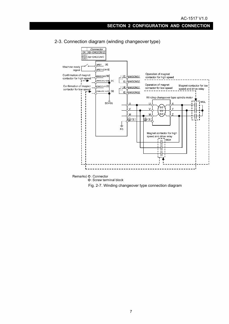
2-3. Connection diagram (winding changeover type)
Fig. 2-7. Winding changeover type connection diagram
AC-1517 V1.0
8
SECTION 2 CONFIGURATION AND CONNECTION
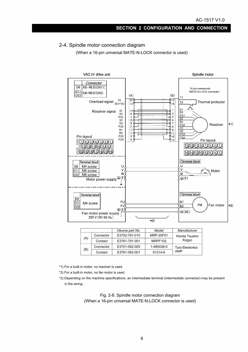
2-4. Spindle motor connection diagram (When a 16-pin universal MATE-N-LOCK connector is used)
*1) For a built-in motor, no resolver is used.
*2) For a built-in motor, no fan motor is used.
*3) Depending on the machine specifications, an intermediate terminal (intermediate connector) may be present in the wiring.
Fig. 2-8. Spindle motor connection diagram
(When a 16-pin universal MATE-N-LOCK connector is used)
Okuma part No. Model Manufacturer Connector E3702-791-010 MRP-20F01
(A) Contact E3761-791-001 MRPF102
Honda Tsushin Kogyo
Connector E3701-082-005 1-480438-0 (B)
Contact E3761-082-001 61314-6 Tyco Electronics AMP

AC-1517 V1.0
9
SECTION 2 CONFIGURATION AND CONNECTION
2-5. Spindle motor connection diagram (When a 10-pin universal MATE-N-LOCK connector is used)
Okuma part No. Model Manufacturer
Connector E3702-791-010 MRP-20F01 (A)
Contact E3761-791-001 MRPF102 Honda Tsushin
Kogyo
Connector E3701-082-059 1-480285-0 (B)
Contact E3761-082-001 61314-6 Tyco Electronics AMP
*1) For a built-in motor, no resolver is used.
*2) For a built-in motor, no fan motor is used. *3) Depending on the machine specifications, an intermediate terminal (intermediate connector) may be present
in the wiring.
Fig. 2-9. Spindle motor connection diagram
(When a 10-pin universal MATE-N-LOCK connector is used)

AC-1517 V1.0
10
SECTION 2 CONFIGURATION AND CONNECTION
2-6. Spindle motor connection diagram (When a 9-pin universal MATE-N-LOCK connector is used)
*1) For a built-in motor, no resolver is used.
*2) For a built-in motor, no fan motor is used. *3) Depending on the machine specifications, an intermediate terminal (intermediate connector) may be present
in the wiring.
Fig. 2-10. Spindle motor connection diagram
(When a 9-pin universal MATE-N-LOCK connector is used)
Okuma part No. Model Manufacturer Connector E3702-791-010 MRP-20F01
(A) Contact E3761-791-001 MRPF102
Honda Tsushin Kogyo
Connector E3703-082-010 350720-1 (B)
Contact E3708-082-164 350689-7 Tyco Electronics AMP

AC-1517 V1.0
11
SECTION 2 CONFIGURATION AND CONNECTION
2-7. Spindle motor connection diagram
(When a dynamic connector is used)
Okuma part No. Model Manufacturer
Connector E3702-791-010 MRP-20F01 (A)
Contact E3761-791-001 MRPF102 Honda Tsushin
Kogyo
Connector E3702-082-040 178289-5 (B)
Contact E3708-082-178 1-175217-2 Tyco Electronics AMP
*1) For a built-in motor, no resolver is used. *2) For a built-in motor, no fan motor is used.
*3) Depending on the machine specifications, an intermediate terminal (intermediate connector) may be present
in the wiring.
Fig. 2-11. Spindle motor connection diagram
(When a dynamic connector is used)
AC-1517 V1.0
12
SECTION 2 CONFIGURATION AND CONNECTION
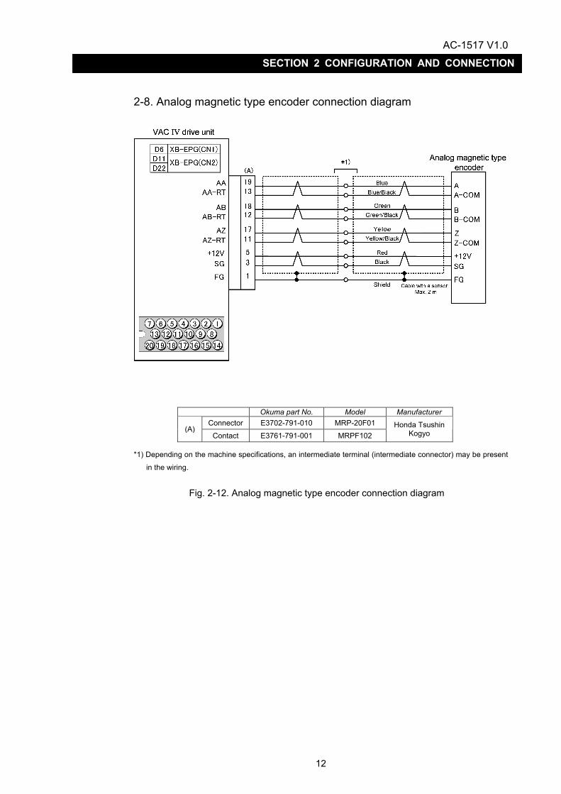
2-8. Analog magnetic type encoder connection diagram
*1) Depending on the machine specifications, an intermediate terminal (intermediate connector) may be present
in the wiring.
Fig. 2-12. Analog magnetic type encoder connection diagram
Okuma part No. Model Manufacturer Connector E3702-791-010 MRP-20F01
(A) Contact E3761-791-001 MRPF102
Honda Tsushin Kogyo

AC-1517 V1.0
13
SECTION 2 CONFIGURATION AND CONNECTION
2-9. Optical type pulse generator connection diagram
*1) Depending on the machine specifications, an intermediate terminal (intermediate connector) may be present in the wiring.
Fig. 2-13. Optical type pulse generator connection diagram
Okuma part No. Model Manufacturer Connector E3702-791-010 MRP-20F01
(A) Contact E3761-791-001 MRPF102
Honda Tsushin Kogyo
(B) Connector E3702-701-003 RM15WTP-8S Hirose Electric

AC-1517 V1.0
14
SECTION 2 CONFIGURATION AND CONNECTION
2-10. Winding changeover circuit connection diagram
Fig. 2-14. Winding changeover circuit connection diagram
Okuma part No. Model Manufacturer Connector E3702-791-010 MRP-20F01
(A) Contact E3761-791-001 MRPF102
Honda Tsushin Kogyo

AC-1517 V1.0
15
SECTION 3 OPERATION STATUS DISPLAY
SECTION 3 OPERATION STATUS DISPLAY
The VACIV drive unit displays operation/error status on the seven-segment LED displays on its front face. LED display has two display modes: normal operation mode and error status mode. In the latter mode, the cause of a pending alarm can be estimated from the displayed error number. VACIV drive units with firmware VAC4111 or a later version installed are capable of displaying both control and coil statuses in normal operation mode. For instructions about how to identify the firmware version, see Appendix 7. A lit LED (DC CHARGE) on the front face of the unit indicates that the main circuit (high-voltage portion) is charged.
Enlarged view of seven-segment LED displays
Fig. 3-1. Layout of status indicator LED displays

AC-1517 V1.0
16
SECTION 3 OPERATION STATUS DISPLAY
1. Display variations until operation preparations are completed Table 3-1. Display variations until operation preparations are completed
Firmware version VAC4110 or earlier version
Firmware version VAC4111 or later version
Before turning on the power
Just after the power is turned on
When the NC unit is launched
During the charging of the main circuit
Operation preparations completed

AC-1517 V1.0
17
SECTION 3 OPERATION STATUS DISPLAY
2. Display in normal operation mode (control mode) Control modes include spindle control mode, spindle/C-axis switching mode, and C-axis control mode. The control status in each of these modes is displayed on the left seven-segment LED display. On a winding changeover type, the right seven-segment LED displays a winding changeover command and a winding status. In the case of a standard type, it is kept unlit. For further information, see Section 3. This display function is available with firmware VAC4111 or a later version.
Table 3-2. Display in the normal operation mode (control mode)
Display on the seven-segment LED display Remarks
When a zero rotation command is issued
- When the spindle is at rest, “02” is displayed.
When a CW rotation command is issued
- During acceleration or deceleration, the “03” display flashes.
- When the spindle rotates at
a constant speed, “03” stops flashing and remains lit.
When a CCW rotation command is issued
- During acceleration or deceleration, the “04” display flashes.
- When the spindle rotates at
a constant speed, the “04” display stops flashing and remains lit.
When an indexing command is issued
When a C-axis control command is issued
- When the mode is shifted from the spindle control mode to the C-axis control mode, the “06” display starts flashing.
- After the NC enters the
C-axis control mode, the “06” display stops flashing and remains lit.

AC-1517 V1.0
18
SECTION 3 OPERATION STATUS DISPLAY
3. Display in normal operation mode (winding status) On a winding changeover type, the right seven-segment LED display indicates a winding changeover command and a winding status - “H” for a high-speed winding or “L” for a low-speed winding. On a standard type, the right seven-segment LED is kept unlit. Shown below are the seven-segment display variations in conjunction with a winding changeover command. The left seven-segment LED display indicates the control status of the control mode. For further information, see Section 2. This display function is available with firmware VAC4111 or a later version.
Table 3-3. Display variations for a winding changeover command (low speed → high speed)
Display on the seven-segment LED display Remarks
During winding changeover (low speed → high speed)
- “H” is displayed on the command indicator seven-segment LED display.
- The entire status indicator
seven-segment LED display flashes.
When winding changeover is completed
- When changing to the high-speed winding is completed, the status indicator seven-segment LED display stops flashing, and illuminates the solid “H”.
Table 3-4. Display variations for a winding changeover command (high speed → low speed)
Display on the seven-segment LED display Remarks
During winding changeover (high speed → low speed)
- “L” is displayed on the command indicator seven-segment display.
- The entire status indicator
seven-segment LED flashes.
When winding changeover is completed
- When changing to a low-speed winding is completed, the status indicator seven-segment LED display stops flashing and illuminates the solid “L”.

AC-1517 V1.0
19
SECTION 3 OPERATION STATUS DISPLAY
4. Display in error status mode The left seven-segment LED display indicates “AL” standing for an alarm, and the right one shows the alarm number.
Table 3-5. Display in the error status mode
Display on the seven-segment LED display Remarks
In case of an alarm
- For alarm numbers and their descriptions, see 2-2 in Section 2.

AC-1517 V1.0
20
SECTION 4 TROUBLESHOOTING
SECTION 4 TROUBLESHOOTING
Troubleshooting is described in the subsections 1 and 2, and procedures for recovery from errors are shown in the subsection 3. (For the layout of the components, see “Appendix 4.”)
:Do not touch the high-voltage portions. They are dangerous.
Before inspecting or repairing the power unit, record the codes indicated on the seven-segment LED display. Then, turn off the power and make sure that the DC CHARGE LED is turned off before inspecting or repairing the power unit.
1. Check points Before taking action described in the subsection 2, check the points according to the following table.
Check point Check method Action
Power supply
Verify that the input power is within the permissible range at input terminals R, S and T of the drive unit. Permissible value: 170 to 242V AC, 50/60Hz
Adjust the input power to the permissible range.
Verify that the connectors*1 to which the cables are connected from the control PC board and an external unit are securely screwed.
Properly connect the cables. Connector
Verify that the board-to-board connectors CN5 to CN7 connecting the control PC board and the power unit are connected all the way to the top.
D6
XB-EPG(CN1) XB-RES(CN11) XB-CHG(CN12)
D11
D22
XB-CHG(CN1) XB-EPG(CN2) XB-RES(CN3)
Table 4-1. Check points
*1)
Cross sectional view

AC-1517 V1.0
21
SECTION 4 TROUBLESHOOTING
2. Errors and their classifications
In case of a failure, take proper actions against it referencing to the subsection indicated in the table below. For procedures for inspecting and replacing the components, see “5. MAINTENANCE AND INSPECTIONS.”
Table 4-2. Error classifications
Error Subsection to refer to
Seven-segment LED display does not light. 2-1
Seven-segment LED display is indicating an error. 2-2
The motor hunts. 2-3
The motor does not run at the specified speed. 2-4
The motor does not run. 2-4
The cutting force has dropped. 2-5
The acceleration or deceleration time has increased. 2-6
Vibration or noise is strong when the motor is running. 2-7

AC-1517 V1.0
22
SECTION 4 TROUBLESHOOTING
2-1. Seven-segment LED display does not light.
Cause Check method Action The power voltage is unusually low or high. See “Table 4-1. Check points.” See Table 4-1.
The board-to-board connector CN7 connecting the control PC board and the power unit is not properly inserted.
See “Table 4-1. Check points.” See Table 4-1.
The power is not supplied from the power unit to the control PC board.
1. Remove the cover.
2. With the power on, measure the voltage across pins 3 and 4 of the board-to-board connector CN7 on the control PC board with a voltmeter to verify it is 300 V DC.
Exercise extreme care not to touch the gate and regenerative control circuits close to the connector concerned because a high voltage is applied to them.
Replace the power unit. See “7. How to replace the power unit” in Section 5.
The control PC board has caused a failure.
Verify that all of the check points above are showing the proper values or properly set.
Replace the control PC board.
See “6. How to replace the control PC board” in Section 5.
:Do not touch high-voltage portions. They are dangerous.
When checking the voltage at board-to-board connector CN7 on the control PC board with the power on, exercise extreme care not to touch the gate and regenerative control circuits close to the connector concerned because a high voltage is applied to them.
Table 4-3
AC-1517 V1.0
23
SECTION 4 TROUBLESHOOTING
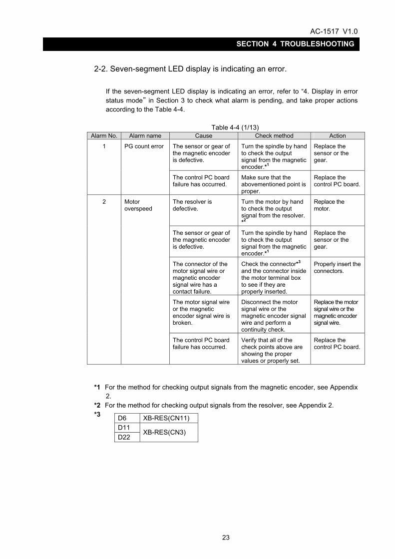
2-2. Seven-segment LED display is indicating an error.
If the seven-segment LED display is indicating an error, refer to “4. Display in error status mode” in Section 3 to check what alarm is pending, and take proper actions according to the Table 4-4.
Table 4-4 (1/13)
Alarm No. Alarm name Cause Check method Action
The sensor or gear of the magnetic encoder is defective.
Turn the spindle by hand to check the output signal from the magnetic encoder.*1
Replace the sensor or the gear.
1 PG count error
The control PC board failure has occurred.
Make sure that the abovementioned point is proper.
Replace the control PC board.
The resolver is defective.
Turn the motor by hand to check the output signal from the resolver. *2
Replace the motor.
The sensor or gear of the magnetic encoder is defective.
Turn the spindle by hand to check the output signal from the magnetic encoder.*1
Replace the sensor or the gear.
The connector of the motor signal wire or magnetic encoder signal wire has a contact failure.
Check the connector*3 and the connector inside the motor terminal box to see if they are properly inserted.
Properly insert the connectors.
The motor signal wire or the magnetic encoder signal wire is broken.
Disconnect the motor signal wire or the magnetic encoder signal wire and perform a continuity check.
Replace the motor signal wire or the magnetic encoder signal wire.
2 Motor overspeed
The control PC board failure has occurred.
Verify that all of the check points above are showing the proper values or properly set.
Replace the control PC board.
*1 For the method for checking output signals from the magnetic encoder, see Appendix 2.
*2 For the method for checking output signals from the resolver, see Appendix 2. *3
D6 XB-RES(CN11) D11 D22
XB-RES(CN3)

AC-1517 V1.0
24
SECTION 4 TROUBLESHOOTING
Table 4-4 (2/13) Alarm No. Alarm name Cause Check method Action
The sensor or gear of the magnetic encoder is defective.
Turn the spindle by hand to check the output signal from the magnetic encoder.*4
Replace the sensor or the gear.
The contact of the connector of the magnetic encoder signal wire is incomplete.
Verify that the connector*5 is properly inserted.
Properly insert the connector.
The magnetic encoder signal wire is broken.
Perform a continuity check with the magnetic encoder signal wire disconnected.
Replace the magnetic encoder signal wire.
3 APA speed (spindle overspeed)
The control PC board failure has occurred.
Verify that all of the check points above are showing the proper values or properly set.
Replace the control PC board.
4 CON speed There is an error in NC software (improper setting of the feed unit).
Check the setting of the feed unit.
Correct the set value.
The machine is overloaded.
Check for any improper cutting conditions and errors in mechanical components, such as a lubrication unit.
Review the cutting conditions, or remove the cause of the mechanical system error.
5 DIFF over
The control PC board failure has occurred.
Verify that all of the check points above are showing the proper values or properly set.
Replace the control PC board.
The connector of the motor signal wire is inserted into a wrong position on the control PC board.
Check which of the connectors*6 on the control PC board the connector is inserted into.
See Fig. 2-1 to Fig. 2-3.
Insert the connector into the correct position.
The contact of the connector of the motor signal wire is incomplete.
Check the connector*6 and the connector inside the motor terminal box to see if they are properly inserted.
Properly insert the connectors.
The motor signal wire is broken.
Perform a continuity check with the motor signal wire disconnected.
Replace the motor signal wire.
The control PC board failure has occurred.
Verify that all of the check points above are showing the proper values or properly set.
Replace the control PC board.
6 Resolver error
The resolver is faulty. Make sure that the same alarm number is displayed with a new control PC board.
Replace the motor.
*4 For the method for checking output signals from the magnetic encoder, see Appendix
2.
D6 XB-EPG(CN1) D11 D22
XB-EPG(CN2)
D6 XB-RES(CN11) D11 D22
XB-RES(CN3)
*5
*6

AC-1517 V1.0
25
SECTION 4 TROUBLESHOOTING
Table 4-4 (3/13) Alarm No. Alarm name Cause Check method Action
The contact of the connector of the optical fiber is incomplete.
Verify that the connector is properly inserted into the connector for optical fiber on the control PC board.
Properly insert the connector.
The optical fiber cable is broken.
Check for broken optical fiber cable.*7
Replace the optical fiber cable.
The SPC6 (a card on the SVP) on the NC side is faulty.
Verify that all of the check points above are showing the proper values or properly set.
Replace the SPC6.
8 Communication error
The control PC board failure has occurred.
Verify that all of the check points above are showing the proper values or properly set.
Replace the control PC board.
9 Command error There is an error in NC software (an undefined or inexecutable command is communicated).
Check communication causing the alarm.
Correct NC software.
The contact between the motor power wire and the terminal block is incomplete.
Verify that the terminal screws are securely tightened.
Securely tighten the terminal screws.
The motor power wire is broken, short-circuited, or grounded.
Perform a continuity check with the motor power wire disconnected from the drive unit and the motor.
Replace the motor power wire.
The contact of the connector of the motor signal wire is incomplete.
Check the connector*8 and the connector inside the motor terminal box to see if they are properly inserted.
Properly insert the connectors.
The motor is faulty. Measure the insulation between the power wire terminal of the motor and the frame.
Replace the motor.
The control PC board failure has occurred.
Verify that all of the check points above are showing the proper values or properly set.
Replace the control PC board.
10 Motor wire overcurrent
The power unit is faulty.
Make sure that the same alarm number is displayed with a new control PC board.
Replace the power unit.
*7 For the method for inspecting the optical fiber cable, see 9 in Section 5.
D6 XB-RES(CN11) D11 D22
XB-RES(CN3)
*8
AC-1517 V1.0
26
SECTION 4 TROUBLESHOOTING
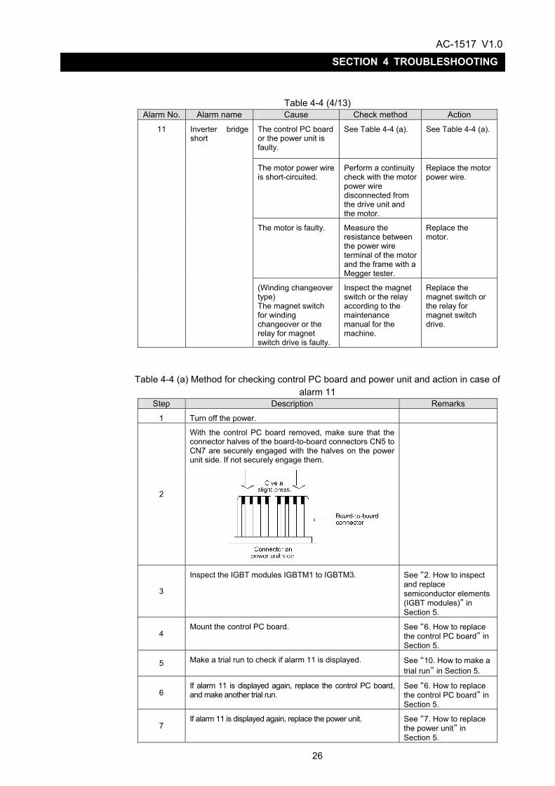
Table 4-4 (4/13) Alarm No. Alarm name Cause Check method Action
The control PC board or the power unit is faulty.
See Table 4-4 (a). See Table 4-4 (a).
The motor power wire is short-circuited.
Perform a continuity check with the motor power wire disconnected from the drive unit and the motor.
Replace the motor power wire.
The motor is faulty. Measure the resistance between the power wire terminal of the motor and the frame with a Megger tester.
Replace the motor.
11 Inverter bridge short
(Winding changeover type) The magnet switch for winding changeover or the relay for magnet switch drive is faulty.
Inspect the magnet switch or the relay according to the maintenance manual for the machine.
Replace the magnet switch or the relay for magnet switch drive.
Table 4-4 (a) Method for checking control PC board and power unit and action in case of alarm 11
Step Description Remarks
1 Turn off the power.
2
With the control PC board removed, make sure that the connector halves of the board-to-board connectors CN5 to CN7 are securely engaged with the halves on the power unit side. If not securely engage them.
3
Inspect the IGBT modules IGBTM1 to IGBTM3.
See “2. How to inspect and replace semiconductor elements (IGBT modules)” in Section 5.
4 Mount the control PC board. See “6. How to replace
the control PC board” in Section 5.
5 Make a trial run to check if alarm 11 is displayed. See “10. How to make a trial run” in Section 5.
6 If alarm 11 is displayed again, replace the control PC board, and make another trial run.
See “6. How to replace the control PC board” in Section 5.
7 If alarm 11 is displayed again, replace the power unit. See “7. How to replace
the power unit” in Section 5.

AC-1517 V1.0
27
SECTION 4 TROUBLESHOOTING
Table 4-4 (5/13) Alarm No. Alarm name Cause Check method Action
Check if an instantaneous power failure occurred when the motor was turned off.
Check the power. Turn on the motor after resetting.
12 Regenerator IGBT short
The control PC board or the power unit is faulty.
See Table 4-4 (b). See Table 4-4 (b).
Table 4-4 (b) Method for checking control PC board and power unit and action in case of
alarm 12 Step Description Remarks
1 Turn off the power.
2 With the control PC board removed, make sure that the connector halves of the board-to-board connectors CN5 to CN7 are securely engaged with the halves on the power unit side.
3
Inspect the IGBT modules IGBTM4 to IGBTM6. See “2. How to inspect and replace semiconductor elements (IGBT modules)” in Section 5.
4 Mount the control PC board. See “6. How to replace
the control PC board” in Section 5.
5 Make a trial run to check if alarm 12 is displayed. See “10. How to make a trial run” in Section 5.
6 If alarm 12 is displayed again, replace the control PC board, and make another trial run.
See “6. How to replace the control PC board” in Section 5.
7 If alarm 12 is displayed again, replace the power unit. See “7. How to replace
the power unit” in Section 5.

AC-1517 V1.0
28
SECTION 4 TROUBLESHOOTING
Table 4-4 (6/13) Alarm No. Alarm name Cause Check method Action
The power voltage is unusually high.
See Table 4-1. See Table 4-1.
The power wire terminal screw is loose.
Turn off the power, and verify that the power wire terminal screw is securely tightened.
Securely tighten the screw.
The regenerative circuit is faulty.
Follow the procedure described in Table 4-4 (b) to check if alarm 13 is displayed.
See Table 4-4 (b).
13 Power circuit abnormal voltage
The power impedance is high.
Check if alarm 13 is displayed only during the deceleration of the motor.
Use a power supply with low power impedance.
The power voltage is low, or an open phase occurs.
See Table 4-1. See Table 4-1.
One or more of the fuses F1R to F3T is blown.
Check the fuses for blowing.
Replace the blown fuse(s).
One or more of the screws fastening the IGBT modules IGBTM4 to IGBTM6 inside the power unit is loose.
Inspect the screws fastening the IGBT modules IGBTM4 to IGBTM6.
Securely tighten the screws.
One or more of the IGBT modules IGBTM4 to IGBTM6 inside the power unit is faulty.
Inspect the IGBT modules IGBTM4 to IGBTM6.
Replace the faulty IGBT module(s).
See “4. How to replace main circuit semiconductor elements” in Section 5.
The board-to-board connector between the control PC board and the power unit is not properly inserted.
See Table 4-1. Properly insert the connector.
The control PC board is faulty.
Verify that all of the check points above are showing the proper values or properly set.
Replace the control PC board.
The power unit is faulty. Make sure that alarm 14 or 15 is displayed with a new control PC board.
Replace the power unit.
14
or
15
Input voltage drop or open phase
The power impedance is high.
Make sure that alarm 14 or 15 is displayed only during the deceleration of the motor.
Use a power supply with low power impedance.
AC-1517 V1.0
29
SECTION 4 TROUBLESHOOTING
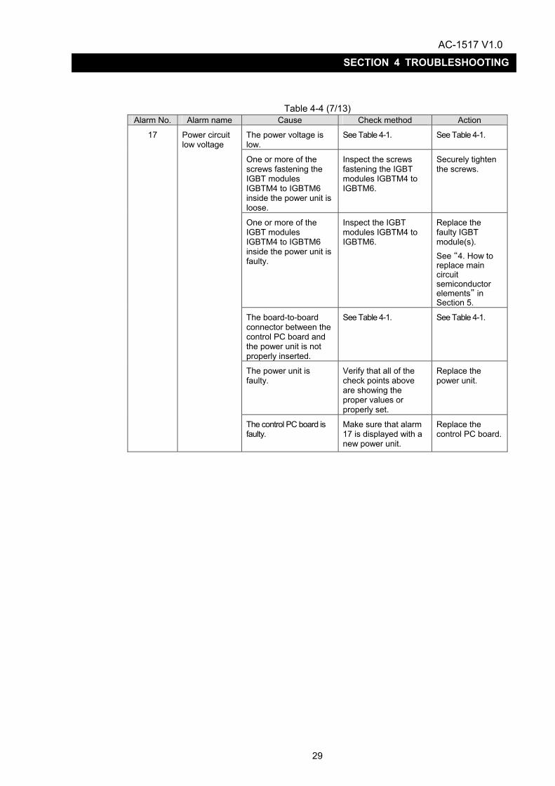
Table 4-4 (7/13) Alarm No. Alarm name Cause Check method Action
The power voltage is low.
See Table 4-1. See Table 4-1.
One or more of the screws fastening the IGBT modules IGBTM4 to IGBTM6 inside the power unit is loose.
Inspect the screws fastening the IGBT modules IGBTM4 to IGBTM6.
Securely tighten the screws.
One or more of the IGBT modules IGBTM4 to IGBTM6 inside the power unit is faulty.
Inspect the IGBT modules IGBTM4 to IGBTM6.
Replace the faulty IGBT module(s). See “4. How to replace main circuit semiconductor elements” in Section 5.
The board-to-board connector between the control PC board and the power unit is not properly inserted.
See Table 4-1. See Table 4-1.
The power unit is faulty.
Verify that all of the check points above are showing the proper values or properly set.
Replace the power unit.
17 Power circuit low voltage
The control PC board is faulty.
Make sure that alarm 17 is displayed with a new power unit.
Replace the control PC board.

AC-1517 V1.0
30
SECTION 4 TROUBLESHOOTING
Table 4-4 (8/13) Alarm No. Alarm name Cause Check method Action
The motor is overloaded.
Check the temperature of the motor.
Review the operation program.
The contact between the fan motor wire and the terminal block is incomplete.
Properly connect the fan motor wire and the terminal block.
The fan motor wire is broken.
Replace the fan motor wire.
The motor cooling fan is faulty.
Since the motor cooling fan does not rotate after the power is turned on: ・ inspect the
connection between the motor terminal block and the fan motor wire; and
・ perform a continuity check.
Replace the motor cooling fan.
The motor cooling fan, the fan guard, the ventilating hole, etc. are contaminated with dust.
Check for contamination.
Clean these items by air blowing or using a vacuum cleaner.
The control PC board is faulty.
Verify that all of the check points above are showing the proper values or properly set.
Replace the control PC board.
The contact of the connector of the motor signal wire is incomplete.
Check the connector*9 and the connector inside the motor terminal box to see if they are properly inserted.
Properly insert the connectors.
The motor signal wire is broken.
Perform a continuity check with the motor signal wire disconnected.
Replace the motor signal wire.
The thermal protector contained in the motor is faulty.
Measure the resistance between the connector inside the motor terminal box and the thermal protector terminal. If the measured resistance is ∞, the thermal protector is faulty.
Replace the motor.
19 Motor overload * When alarm
19 occurs while the motor is running
The control PC board is faulty.
Verify that all of the check points above are showing the proper values or properly set.
Replace the control PC board.
*9
D6 XB-EPG(CN1) D11 D22
XB-EPG(CN2)

AC-1517 V1.0
31
SECTION 4 TROUBLESHOOTING
Table 4-4 (9/13) Alarm No. Alarm name Cause Check method Action
The board-to-board connector CN7 between the control PC board and the power unit is not properly inserted.
――――― Properly insert the connector.
The heat sink cooling fan is faulty.
Verify that the heat sink cooling fan starts working when the power is turned on.
Replace the power unit.
The heat sink cooling fan is contaminated with dust.
Check the back of the power unit for contamination.
Clean the heat sink cooling fan by air blowing or using a vacuum cleaner.
Operation in overloaded condition.
Review the cutting conditions and tools.
The control PC board is faulty.
Verify that all of the check points above are showing the proper values or properly set.
Replace the control PC board.
20 Heat sink overload
The power unit is faulty. Make sure that alarm 20 is displayed with a new control PC board.
Replace the power unit.
21 VAC data setting There is an error in NC software.
Check VAC PBU data or online change parameters.
Correct wrong data.
22
Excessive in-VAC speed command
There is an error in the spindle mechanical system.
Verify that the mechanical system is in normal condition.
Remove error elements, if any.
The connector of the magnetic encoder signal wire is connected into a wrong position on the control PC board.
Check which of the connectors*10 on the control PC board the connector is inserted.
See Fig. 2-1 to Fig. 2-3.
Insert the connector into the correct position.
The contact of the magnetic encoder signal is incomplete.
Check the connector*10 to see if it is properly inserted.
Properly insert the connector.
The magnetic encoder signal wire is broken.
Perform a continuity check with the signal wire disconnected.
Replace the signal wire.
23 Magnetic PG error
The sensor of the magnetic encoder is faulty.
Turn the spindle by hand to check the output signal from the magnetic encoder.*11
Replace the sensor.
*10 *11 For the method for checking output signals from the magnetic encoder, see Appendix
2.
D6 XB-EPG(CN1) D11 D22
XB-EPG(CN2)

AC-1517 V1.0
32
SECTION 4 TROUBLESHOOTING
Table 4-4 (10/13) Alarm No. Alarm name Cause Check method Action
24
Magnetic PG marker latch data error
The sensor or gear of the magnetic encoder is faulty.
Turn the spindle by hand to check the output signal from the magnetic encoder.*12
Replace the sensor or the gear.
The motor is overloaded. ―――――
Review the cutting conditions and tools.
The motor power wire is broken, or its contact is incomplete.
Inspect the motor power wire.
Properly connect the motor power wire.
The motor signal wire is defective (incomplete connection, wrong connection, etc.).
Inspect the motor signal wire.
Properly connect the motor signal wire.
The power unit is faulty. Replace the power unit.
The control PC board is faulty.
Verify that all of the check points above are showing the proper values or properly set.
Replace the control PC board.
30
Excessive speed deviation
(Winding changeover type) The magnet contactor for winding changeover or the relay for magnet contactor drive is faulty.
Inspect the magnet contactor or the relay according to the maintenance manual for the machine.
Replace the magnet switch for winding changeover or the relay for magnet switch drive.
The magnet contactor for winding changeover or the relay for magnet contactor drive is malfunctioning.
Inspect the magnet contactor or the relay according to the maintenance manual for the machine.
Replace the magnet switch for winding changeover or the relay for magnet switch drive.
The signal wire is defective (wire breakage, incomplete contact, etc.).
Inspect the signal wire for control.
Properly connect the signal wire for control.
31 Winding changeover error
The control PC board is faulty.
Verify that all of the check points above are showing the proper values or properly set.
Replace the control PC board.
32 RAM error The control PC board is faulty.
Replace the control PC board.
*12 For the method for checking output signals from the magnetic encoder, see Appendix
2.

AC-1517 V1.0
33
SECTION 4 TROUBLESHOOTING
Table 4-4 (11/13) Alarm No. Alarm name Cause Check method Action
41 Converter link error
The power unit is faulty. Replace the power unit.
The power voltage is unusually high.
See Table 4-1. See Table 4-1.
The power wire terminal screw is loose.
Turn off the power, and verify that the power wire terminal screw is securely tightened.
Securely tighten the screw.
The regenerative circuit is faulty.
Follow the procedure described in Table 4-4 (b) to check if alarm 42 is displayed.
See Table 4-4 (b).
The power impedance is high.
Check if alarm 42 is displayed only during the deceleration of the motor.
Use a power supply with low power impedance.
The power voltage is low, or an open phase occurs.
See Table 4-1. See Table 4-1.
One or more of the fuses F1R to F3T is blown.
Check the fuses for blowing.
Replace the blown fuse(s).
One or more of the screws fastening the IGBT modules IGBTM4 to IGBTM6 inside the power unit is loose.
Inspect the screws fastening the IGBT modules IGBTM4 to IGBTM6.
Securely tighten the screws.
One or more of the IGBT modules IGBTM4 to IGBTM6 inside the power unit is faulty.
Inspect the IGBT modules IGBTM4 to IGBTM6.
Replace the faulty IGBT module(s).
See “4. How to replace main circuit semiconductor elements” in Section 5.
The board-to-board connector between the control PC board and the power unit is not properly inserted.
See Table 4-1. Properly insert the connector.
The control PC board is faulty.
Make sure that alarm 42 is displayed with a new power unit.
Replace the control PC board.
42 Abnormal inverter DC bus voltage
The power unit is faulty. Make sure that alarm 42 is displayed with a new control PC board.
Replace the power unit.

AC-1517 V1.0
34
SECTION 4 TROUBLESHOOTING
Table 4-4 (12/13) Alarm No. Alarm name Cause Check method Action
The control PC board is faulty.
――――― Replace the control PC board.
51 Control PC board error
One or more of the board-to-board connectors CN5 to CN7 connecting the control PC board and the power unit is improperly inserted.
See “Table 4-1. Check points.”
See Table 4-1.
52 Abnormal control voltage±12 V/+24 V
53 OPF error
58
Abnormal power for magnetic encoder
59 Abnormal power for encoder
60 Abnormal control power + 3.3 V
61 Abnormal control power 5 V
62 Gate signal error
70 IR1 MAIN loop error
71 IR2 MAIN loop error
72 INT4 loop error
73 INT3 loop error
74 INT2 loop error
75 IR3 MAIN loop error
76 Access error
78 Parity error
79 Watchdog error
The control PC board is faulty.
――――― Replace the control PC board.

AC-1517 V1.0
35
SECTION 4 TROUBLESHOOTING
Table 4-4 (13/13) Alarm No. Alarm name Cause Check method Action
80 IRQ7 interruptIRQ4 interrupt
81 NMI interrupt
82 General imparity command
83 Slot imparity command
84 CPU address error
85 DMA address errorDMAC/DTC address error
86 Undefined trap command
87 Undefined interrupt
88 DMAC
89 ITU MTU
90 SCI
91 REF BSC
92 A/D
93 System reserve
94 User break
95 DTC
96 CMT 97 I/O
The control PC board is faulty.
――――― Replace the control PC board.
AC-1517 V1.0
36
SECTION 4 TROUBLESHOOTING
2-3. The motor hunts.
Table 4-5 Cause Checking method Action
The motor power or signal wire is defective (incomplete contact, wrong connection, etc.).
Inspect the motor power and signal wires. Properly connect the motor power and signal wires.
One or more of the IGBT modules IGBTM1 to IGBTM6 is faulty.
Inspect the IGBT modules IGBTM1 to IGBTM3. See “2. How to inspect and replace semiconductor elements (IGBT modules)” in Section 5.
Replace the faulty IGBT module(s).
The control PC board is faulty.
Verify that all of the check points above are showing the proper values or properly set.
Replace the control PC board.
(Winding changeover type)
The contact of the magnet contactor for high speed/low speed is incomplete.
Inspect the magnet contactor according to the maintenance manual for the machine.
Replace the magnet contactor.
(Winding changeover type)The motor power wire is not properly connected to the magnet contactor for high speed/low speed.
Inspect the connection of the motor power wire by making reference to the electric drawing.
Properly connect the motor power wire.

AC-1517 V1.0
37
SECTION 4 TROUBLESHOOTING
2-4 The motor does not run at the commanded speed.
Regarding a winding changeover type, a permissible spindle speed range is specified for each type of winding (high-speed winding/low-speed winding). Set winding and speed commands suitable for the permissible spindle speed ranges shown below. For specific values, see the instruction manual for the machine.
- High-speed winding: 0 to maximum motor speed - Low-speed winding: 0 to maximum speed for low-speed winding
Table 4-6 Cause Checking method Action
The drive unit is faulty. By giving a rotation command, the seven-segment LED display enters the error status mode.
See “2-2. Seven-segment LED display is indicating an error.” in Section 4.
The motor power wire is defective (wire breakage, wrong connection, etc.).
Inspect the motor power wire. Properly connect the motor power wire.
The resolver is faulty. Check the signal from the resolver.*1 Replace the motor.
The magnetic encoder is faulty.
Check the output signal from the magnetic encoder.*2
Replace the sensor of the magnetic encoder.
The control PC board is faulty.
Verify that all of the check points above are showing the proper values or properly set.
Replace the control PC board.
The power unit is faulty. Verify that all of the check points above are showing the proper values or properly set.
Replace the power unit.
(Winding changeover type)The magnet switch for coil switching or the relay for magnet switch drive is faulty.
See the maintenance manual for the machine.
Replace the magnet switch for winding changeover or the relay for magnet switch drive.
*1 For the method for checking output signals from the resolver, see Appendix 2. *2 For the method for checking output signals from the magnetic encoder, see Appendix
2.

AC-1517 V1.0
38
SECTION 4 TROUBLESHOOTING
2-5. The cutting force has dropped.
Table 4-7 Cause Checking method Action
A torque limit command is applied.
――――― Cancel the torque limit command.
The cause of the problem exists close to the spindle of the machine.
See the maintenance manual for the machine.
See the maintenance manual for the machine.
The control PC board is faulty.
Verify that all of the check points above are showing the proper values or properly set.
Replace the control PC board.

AC-1517 V1.0
39
SECTION 4 TROUBLESHOOTING
2-6. The acceleration or deceleration time has increased.
Table 4-8 Cause Checking method Action
The load is heavy. Check the load (value) displayed on the NC screen.
Remove the cause of the heavy load.
A torque limit command is applied.
――――― Cancel the torque limit command.
The power voltage is high. See Table 4-1. See Table 4-1.
The motor power wire is broken, or its contact is incomplete.
Inspect the motor power wire. Properly connect the motor power wire.
One or more of the IGBT modules is faulty.
Inspect the IGBT modules. See “2. How to inspect and replace semiconductor elements (IGBT modules)” in Section 5.
Replace the faulty IGBT module(s).
The control PC board is faulty.
Verify that all of the check points above are showing the proper values or properly set.
Replace the control PC board.
The power impedance is high.
Only the deceleration time increases.
See the instruction manual for the machine.
Use a power supply with low power impedance.
AC-1517 V1.0
40
SECTION 4 TROUBLESHOOTING
2-7. Vibration or noise is strong when the motor is running.
As a method for locating whether the cause of a problem is present in the electric or mechanical system, run the motor free (uncontrolled state). Follow the procedure described below to run the motor free.
If “vibration or noise is still strong” even if the motor is running free, the cause of the problem lies in the mechanical system, not the electric system.
① Run the motor with a rotation command given to it. ② Disconnect the optical fiber connector XB-OPT (CNOFS) of the drive unit. ③ A communication error alarm is issued, and the motor starts to run free.
Table 4-9
Cause Checking method Action
The mounting of the motor is improper.
Check the motor to see if it is properly mounted and coupled with the spindle.
Mount or couple the motor with the spindle from the beginning.
The cause of the problems lies in the motor or wiring.
See Table 4-5. See Table 4-5.
The motor is faulty. Verify that all of the check points above are showing the proper values or properly set.
Replace the motor.
When the motor is running in neutral (uncontrolled state), stay away from the rotating part of the motor. Exercise care not to apply excessive force to the root of the optical fiber connector XB-OPT (CNOFS) of the drive unit when disconnecting it. Failure to follow this instruction will cause the optical fiber to break.

AC-1517 V1.0
41
SECTION 4 TROUBLESHOOTING
3. Recovery from errors If the seven-segment LED display is indicating an error, it is necessary to remove the cause of the error and reset the alarm to recover from that error status. Alarms are classified into four levels according to the processing in case of an alarm and the recovering method.
Table 4-10 Alarm level Processing in
case of alarm Recovering
method Nature of alarm
Level 1a
The unit goes into alarm level 1 mode. [Immediately shut off]
Turn off the three-phase breaker of the machine, and turn it on again.
An alarm, such as an exception, that requires the initialization of hardware.
Level 1b
The unit goes into alarm level 1 mode. [The shutoff of the
current after deceleration to a stop is standard processing.]
Turn off the operation power to the NC, and turn it on again.
An alarm that requires the initialization of parameters, etc.
Level 2
The unit goes into an alarm status in the main mode*1 in which the alarm was issued. [The processing depends on the main mode in which an alarm is issued.]
Reset the power from the operation panel.[A reset
command will be issued in each mode.]
An alarm that may occur under a certain cutting conditions, such as DIFF over.
Level 3
The unit informs the NC of the issuance of alarm level 3, remains in normal operation for 30 seconds, and goes into alarm level 2.
Reset the NC from the operation panel.[A reset command
will be issued in each mode.]
An overload-related alarm.
*1 ”Main mode” means velocity control mode (the mode executed with a regular S
command) or position control mode (the mode for C-axis control).

AC-1517 V1.0
42
SECTION 5 MAINTENANCE AND INSPECTIONS
SECTION 5 MAINTENANCE AND INSPECTIONS
1. Instruments and parts for maintenance Table 5-1 shows the instruments to be used for maintenance and inspections.
Table 5-1 Name Type/Specification Application
AC voltmeter 300 V Measuring power voltage
Analog tester Commercial tester Checking resistance
Screwdriver Large, medium, small
Spanner 8-mm
Box wrench 13-mm
Replacing main circuit
semiconductor elements

AC-1517 V1.0
43
SECTION 5 MAINTENANCE AND INSPECTIONS
Table 5-2 lists the parts required for maintenance among those used for a drive unit. The elements with a number in parentheses in the table are compatible with the upper ones.
Table 5-2
Power unit model
Model Okuma part No. Item
D6
D11
D22
Remarks
IGBTNM1 -IGBTM3
6MBI100A-060/MG100J6ES52 100A 600V Fuji Electric/Toshiba
E4443-722-043 2
IGBTM4 -IGBTM6
CM150DY-12E/2MBI150LB-060 150A 600V Mitsubishi Electric/Fuji Electric
E4443-820-021 3
IGBTM4 -IGBTM6
2MBI150N-060 150A 600V Fuji Electric
E4443-820-021 (3)
IGBTM4 -IGBTM6
2MBI150-060 150A 600V Fuji Electric
E4443-722-029 (3)
IGBTM1 -IGBTM3
CM200DY-12E/2MBI200LB-060 200A 600V Mitsubishi Electric/Fuji Electric
E4443-820-022 3
IGBTM1 -IGBTM3
2MBI200N-060 200A 600V Fuji Electric
E4443-820-022 (3)
IGBTM4 -IGBTM6
CM300DY-12E/2MBI300LB-060 300A 600V Mitsubishi Electric/Fuji Electric
E4443-820-029 3
IGBTM1 -IGBTM3
CM400DY-12E/2MBI400L-060 400A 600V Mitsubishi Electric/Fuji Electric
E4443-820-030 3
IGBTM1 -IGBTM6
CM400DY-12H 400A 600V Mitsubishi Electric
E4443-820-042 (6)Replace all IGBTs and the power board (V2.6) at the same time.
IGBT
mod
ule
IGBTM1 -IGBTM6 R19-R30
CM400DY-12H 400A 600V Mitsubishi Electric ERDS1VJ100 10Ω
S4443-820-K01 (1)
Replace all resistors (R19 to R30) whenever all IGBTs are replaced.
DM1 RM200HA-20F 200A 600V Mitsubishi Electric
E2714-820-006 1
DM1 D200LC40B 200A 600V Shindengen
E2771-300-003 1
DM1-DM* PC1008 100A 800V Nihon Inter Electronics
- 2
Dio
de m
odul
e
DM1-DM* RM100C2Z-H 100A 800V Mitsubishi Electric
E2714-820-005 1 (2)
F-7161-5A 5A 250V Fuji Electric
E2442-722-003 5 5 5
Fuse
F-7161-0.5A 0.5A 250V Fuji Electric
E2442-727-004 2 2 3
AC-1517 V1.0
44
SECTION 5 MAINTENANCE AND INSPECTIONS
2. Procedures for inspecting and replacing semiconductor elements (IGBT
modules)
Keep the followings in mind when inspecting and replacing main circuit semiconductor elements:
- Securely tighten all screws unfastened in inspecting or replacing semiconductor elements in
the correct positions. One missing or loose screw could cause malfunction. - Exercise care not to drop screws.
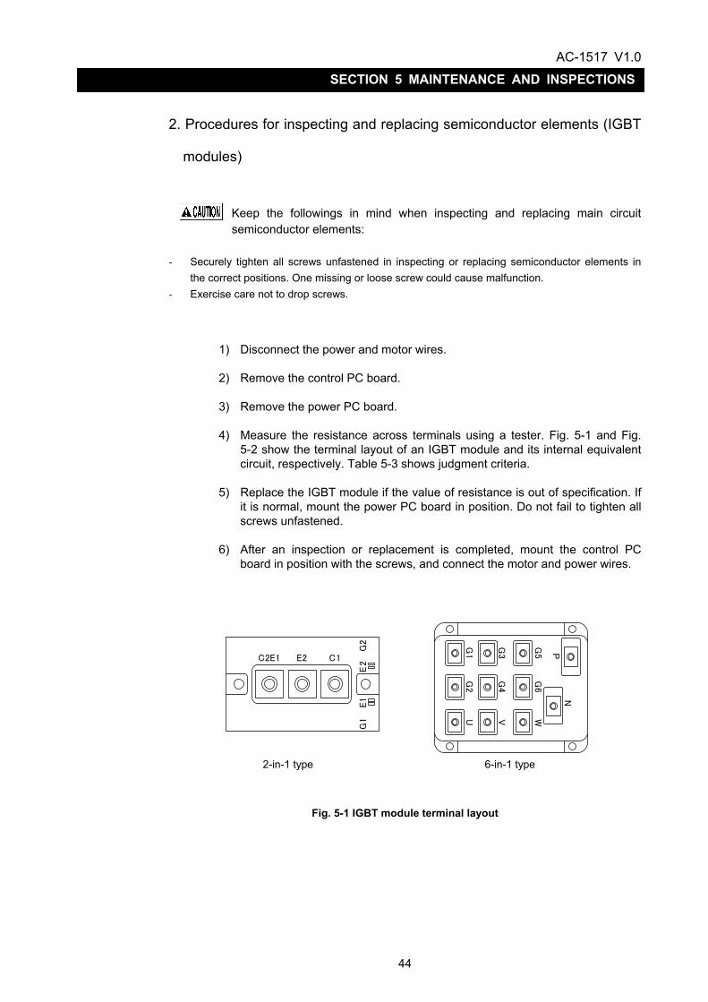
1) Disconnect the power and motor wires. 2) Remove the control PC board. 3) Remove the power PC board. 4) Measure the resistance across terminals using a tester. Fig. 5-1 and Fig.
5-2 show the terminal layout of an IGBT module and its internal equivalent circuit, respectively. Table 5-3 shows judgment criteria.
5) Replace the IGBT module if the value of resistance is out of specification. If
it is normal, mount the power PC board in position. Do not fail to tighten all screws unfastened.
6) After an inspection or replacement is completed, mount the control PC
board in position with the screws, and connect the motor and power wires.
2-in-1 type 6-in-1 type
Fig. 5-1 IGBT module terminal layout
C2E1 E2 C1
G2
E2
E1
G1 U
G2
G1
VG
4G
3
WG
6G
5
NP

AC-1517 V1.0
45
SECTION 5 MAINTENANCE AND INSPECTIONS
Table 5-3 Table of judgment criteria IGBT terminal
Positive side tester terminal
Negative side tester terminal
Normal value Abnormal value
C E Several dozen to
several hundred Ω *1
0Ω, ∞
E C ∞ *2 Several hundred Ω or below
C B ∞ Several kΩ or below
G C ∞ Several kΩ or below
G E ∞ Several kΩ or below
E G ∞ Several kΩ or below
*1 Measure resistance with the measurement range set to x1.
*2 Short across G and E when measuring resistance. If they are not shorted, accurate measurement will not be expected.
Fig. 5-2 IGBT module equivalent circuit (6-in-1 type)
Fig. 5-2 IGBT module equivalent circuit (2-in-1 type)
C1
C2E1
G1 E1 G2 E2
E2
P(+)
N(-)
G2
G1 G3 G5
G4 G6
U
V
W

AC-1517 V1.0
46
SECTION 5 MAINTENANCE AND INSPECTIONS
3. Procedures for inspecting semiconductor elements (diode modules)
1) Remove the control and power PC boards.
2) Measure the resistance across all terminals of the diode module using a tester.
IGBT terminal
Positive side tester terminal
Negative side tester terminal
Normal value Abnormal value
1 2 ∞ Several hundred
Ω or below
1 3 Several dozen to several hundred
Ω ∞
2 1 Several dozen to several hundred
Ω ∞
3 1 ∞ Several hundred
Ω or below
3) Replace the diode module if any resistance value is abnormal. (See “4. Procedures for replacing semiconductor elements” in Section 5.)
4) When all resistance values are normal, mount the power and control PC boards in place. Do not fail to tighten all screws unfastened.
1 2 3
1 2 3
Fig. 5-3 Diode module terminal layout
Fig. 5-4 Diode module equivalent circuit
Table 5-4 Table of judgment

AC-1517 V1.0
47
SECTION 5 MAINTENANCE AND INSPECTIONS
4. Procedures for replacing semiconductor elements If any of the main circuit conductor elements is judged defective by the checking methods described thus far, replace it according to the procedure shown in Table 5-5.
Table 5-5 Step Description Remarks
1 Remove all screws and gate connectors from the power PC board, and detach the board from the module.
2 Remove the screws and the gate wires from the module, and detach the module.
3
Apply silicone compound to the back of the new module.
Silicone compound is used to improve the adhesion between the module and the mounting face and provide a higher cooling effect.
4 Securely tighten the screws of the new module.
Mount the module in the correct direction.
5 Connect the gate wires to the new module.
Protect IGBTs, which are MOS-based elements, from static electricity.
6 Fasten the power PC board with the screws unfastened, and securely connect the connectors.
Do not fail to tighten all screws.
Keep the antistatic mat attached to the gate terminals of the module just before the gate wires are connected.
AC-1517 V1.0
48
SECTION 5 MAINTENANCE AND INSPECTIONS
5. Procedures for inspecting and replacing fuses
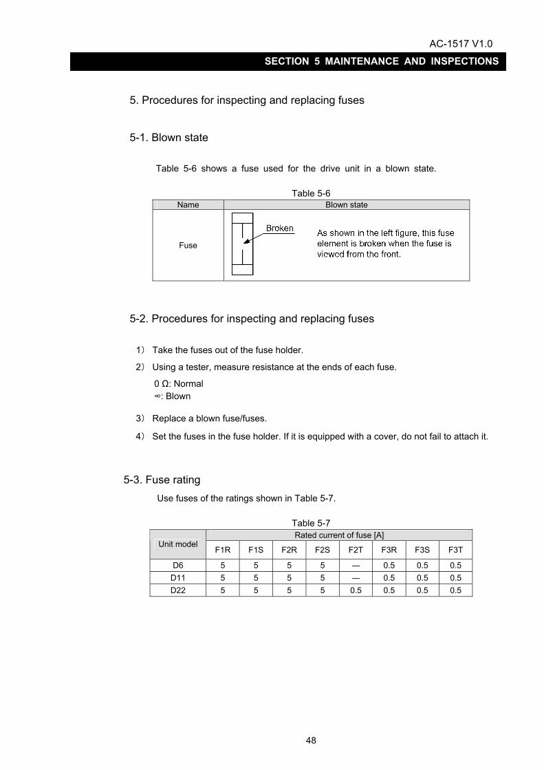
5-1. Blown state Table 5-6 shows a fuse used for the drive unit in a blown state.
Table 5-6 Name Blown state
Fuse
5-2. Procedures for inspecting and replacing fuses
1) Take the fuses out of the fuse holder.
2) Using a tester, measure resistance at the ends of each fuse.
0 Ω: Normal ∞: Blown
3) Replace a blown fuse/fuses.
4) Set the fuses in the fuse holder. If it is equipped with a cover, do not fail to attach it.
5-3. Fuse rating Use fuses of the ratings shown in Table 5-7.
Table 5-7 Rated current of fuse [A]
Unit model F1R F1S F2R F2S F2T F3R F3S F3T
D6 5 5 5 5 ― 0.5 0.5 0.5 D11 5 5 5 5 ― 0.5 0.5 0.5 D22 5 5 5 5 0.5 0.5 0.5 0.5
AC-1517 V1.0
49
SECTION 5 MAINTENANCE AND INSPECTIONS
6. Procedures for replacing the control PC board Table 5-8 shows the procedure for replacing the control PC board.
Table 5-8 Procedure for replacing the control PC board
Step Description Reference item
1 Turn off the power.
2 Unfasten the bolts clamping the cover, and remove it.
3 Remove the control PC board. Table 5-9
4 Mount the prepared control PC board. Table 5-10
5 Make a trial run. 10 in Section 5
6 Attach and fasten the cover with the bolts.
Tables 5-9 and 5-10 show the procedure for removing the control PC board and the procedure for mounting it, respectively. For the connector layout, see Figures 1-1 to 1-3 in Section 2.
Table 5-9 Procedure for removing the control PC board Step Description
1
Unfasten the screws clamping the connectors CN1 to CN3, and remove the connectors. Remove the connector for optical fiber as well.
2 Remove the screws (M4) fastening the control PC board.
3 Holding the control PC board at the upper and lower sides, draw it toward you until it is removed.
Table 5-10 Procedure for mounting the control PC board
Step Description
1
Engage the connector on the control PC board completely with the board-to-board connector.
2 Fasten the control PC board with the screws (M4).
3 Fasten the connectors CN1 to CN3 with the screws.

AC-1517 V1.0
50
SECTION 5 MAINTENANCE AND INSPECTIONS
7. Procedures for replacing the power unit Table 5-11 shows the procedure for replacing the power unit.
Table 5-11 Procedure for replacing the power unit Step Description Reference
item
1 Turn off the power.
2 Disconnect the motor and power wires.
3 Unfasten the screws clamping the connectors CN1 to CN3, and remove the connectors and the optical fiber.
4 Unfasten the bolts clamping the cover, and remove it.
5 Remove the control PC board. Table 5-9
6 Remove the power unit.
7 Mount the prepared power unit.
8 Connect the connectors CN1 to CN3 and the optical fiber, and fasten them with the screws.
9 Make a trial run. 10 in Section 5
10 Attach and fasten the cover with the bolts.
Before replacing the power unit, turn off the power, and make sure that the DC CHARGE LED is turned off.
The power unit is heavy. Lift it with a crane or by another means when removing and mounting it.

AC-1517 V1.0
51
SECTION 5 MAINTENANCE AND INSPECTIONS
8. Procedures for replacing the whole drive unit Table 5-12 shows the procedure for replacing the whole drive unit, including the control PC board and the power unit.
Table 5-12 Procedure for replacing the whole unit Step Description Reference
item
1 Turn off the power.
2 Disconnect the motor and power wires.
3 Unfasten the screws clamping the connectors CN1 to CN3, and remove the connectors and the optical fiber.
4 Remove the drive unit.
5 Mount the prepared drive unit.
6 Connect the connectors CN1 to CN3 and the optical fiber, and fasten them with the screws.
7 Remove the cover, and check if the settings of the switches are correct. Appendix 3
8 Connect the motor and power wires, and make a trial run. 10 in Section 5
9 Attach and fasten the cover with the bolts.
Before replacing the whole drive unit, turn off the power, and make sure that the DC CHARGE LED is turned off.
The power unit is heavy. Lift it with a crane or by another means when removing and mounting it.

AC-1517 V1.0
52
SECTION 5 MAINTENANCE AND INSPECTIONS
9. Procedures for inspecting the optical fiber cable
As shown in Fig. 6-1, expose either optical fiber connector to light. The cable is functioning if the other connector is lit.
Exercise care not to apply excessive force to the root of the optical fiber connector. Failure to follow this instruction will cause the optical fiber to break.
Fig. 6-1

AC-1517 V1.0
53
SECTION 5 MAINTENANCE AND INSPECTIONS
10. Procedures for conducting a trial run Follow the procedure shown in Table 5-13 to conducting a trial run after replacing any part or unit.
Table 5-13 Procedure for conducting a trial run. Step Description
1 Make sure that the unit model is correct.
2 Turn on the power, and make sure that the drive unit and the motor cooling fan are running.
3 Make sure that 01 is displayed on the seven-segment LED just after the main breaker is turned on and changes to 02 when the NC starts to run after the power is turned on.
4 Give a rotation command to check C.W. and C.C.W..
5 Check the performance of the unit in all speed ranges and in potion control mode.

AC-1517 V1.0
54
APPENDIX 1 FILES STORED ON CONTROL FLOPPY DISK
APPENDIX 1 FILES STORED ON CONTROL FLOPPY DISK
The parameters for spindle motor control are stored in the files shown below.
- Common file The parameters for spindle indexing, motor data, gear ratios, etc. are set in this file. This file also holds parameters set by users (for example, parameters for spindle indexing). Periodically make a backup copy of these parameters on floppy disk B.
- File for synchronized tapping specifications
The parameters for synchronized tapping, the number of gear steps, the permissible synchronized tapping speed range in each gear, etc.

AC-1517 V1.0
55
APPENDIX 2 DESCRIPTION OF MONITOR TERMINALS
APPENDIX 2 DESCRIPTION OF MONITOR TERMINALS The waveform of the VACIV can be observed by connecting an oscilloscope to the monitor terminals.
1. Monitor terminal layout
VACⅣ-D6
GND IU IV
IS IR
A B Z R1M2 M3
M1
S2S1
M4 GND
VACⅣ-D11VACⅣ-D22
M1
M2 M3
IS IR
A B Z R1S2
S1
GND IU IV
M4 GND
M1: Motor velocity M2: Motor output torque M3: None M4: None A: Magnetic encoder phase A signal B: Magnetic encoder phase B signal Z: Magnetic encoder phase Z signal R1: Resolver feedback signal S1: Resolver magnetization signal S2: Resolver magnetization signal IS: DC bus P side current IR: DC bus N side current IU: Motor current phase U IV: Motor current phase V GND: Connect the common terminal of the oscilloscope.

AC-1517 V1.0
56
APPENDIX 2 DESCRIPTION OF MONITOR TERMINALS
2. Description of monitor terminal signals
Monitor terminal Description Waveform (example)
M1 Motor velocity
- Output voltage range: -5 V to +5 V - Unit: top speed at 5 V (set in PBU file)
M2 Motor output torque - Output voltage range: -5 V to +5 V - Unit: peak torque at 5 V (set in PBU
file)
A Magnetic encoder phase A signal
- Vpp in right figure: 2.6 to 4.6 V (3.3 V when gap is properly adjusted)
B Magnetic encoder phase B signal
- Vpp in right figure: 2.6 to 4.6 V (3.3 V when gap is properly adjusted)
Z
Magnetic encoder phase Z signal
- Vz1 in right figure: 1.4 V or over - Vz2 in right figure: 0.5 V or over - t1 and t2 in right figure: 0.1 to 0.4T
(T varies according to the speed.)
R1
Resolver signal
- Vpp in right figure: 6.0 V (typ) - T in right figure: Approx. 0.128 ms
(7.81 kHz) (T slightly varies according to the speed.)
S1 S2
Resolver magnetization signal
- Vpp in right figure: Approx. 17.6 V - T in right figure: 128 µs
ls lr
DC bus current - Unit: A
lu lv
Motor current
- Unit: A
V
0
I s 力行時(主軸加速中、切削中など)
t
V
0
I r 回生時(主軸減速中など)
t

AC-1517 V1.0
57
APPENDIX 3 SWITCH SETTINGS
APPENDIX 3 SWITCH SETTINGS Switches are located on the control PC board of the VACIV drive unit. Set all of the switches SW1 to SW6 to OFF.
AC-1517 V1.0
58
APPENDIX 4 COMPONENT LAYOUT
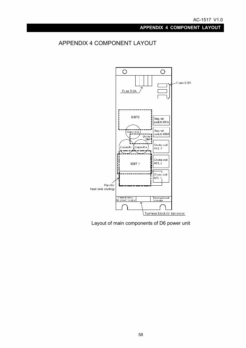
APPENDIX 4 COMPONENT LAYOUT
Layout of main components of D6 power unit
AC-1517 V1.0
59
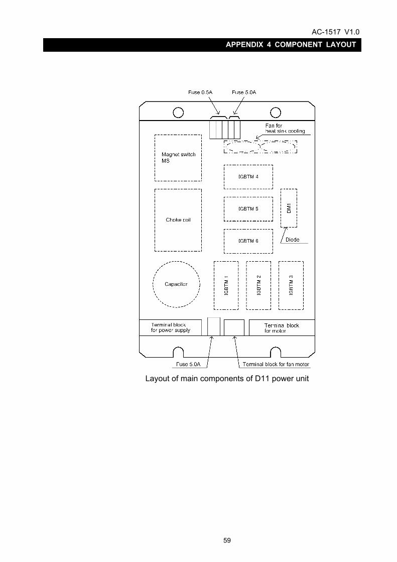
APPENDIX 4 COMPONENT LAYOUT
Layout of main components of D11 power unit

AC-1517 V1.0
60
APPENDIX 4 COMPONENT LAYOUT
Layout of main components of D22 power unit

AC-1517 V1.0
61
APPENDIX 5 APPEARANCE AND WEIGHT OF UNIT
APPENDIX 5 APPEARANCE AND WEIGHT OF UNIT
Appearance of VACIV-D6 unit
Appearance of VACIV-D11 unit

AC-1517 V1.0
62
APPENDIX 5 APPEARANCE AND WEIGHT OF UNIT
Appearance of VACIV-D22 unit

AC-1517 V1.0
63
APPENDIX 6 COMPATIBILITY TABLE
APPENDIX 6 COMPATIBILITY TABLE The compatibility among control PC boards is shown below.
Alternative control PC board
1006
-110
7 V
AC B
OAR
D 3
1006
-111
0 V
AC3
GD
BO
ARD
1006
-111
1 V
AC3
CPU
BO
ARD
1006
-150
7 V
AC B
OAR
D 4
1006
-151
0 V
AC4
CPU
BO
ARD
1006
-151
1 V
AC4
GD
BO
ARD
Remarks
1006-1107 VAC BOARD 3
1006-1110 VAC3 GD BOARD *1 *1 *1 Replace this board together with 1006-1510 and 1006-1511.
1006-1111 VAC3 CPU BOARD *1 *1 *1 Replace this board together with 1006-1510 and 1006-1511.
1006-1507 VAC BOARD 4
1006-1510 VAC4 CPU BOARD Con
trol P
C b
oard
m
ount
ed o
n un
it
1006-1511 VAC4 GD BOARD
AC-1517 V1.0
64
APPENDIX 7 IDENTIFICATION OF FIRMWARE VERSION
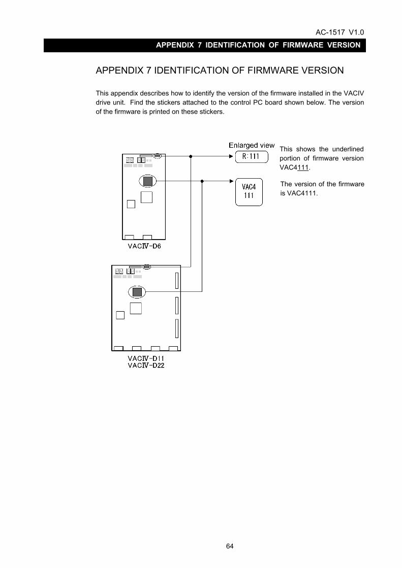
APPENDIX 7 IDENTIFICATION OF FIRMWARE VERSION This appendix describes how to identify the version of the firmware installed in the VACIV drive unit. Find the stickers attached to the control PC board shown below. The version of the firmware is printed on these stickers.
This shows the underlinedportion of firmware versionVAC4111.
The version of the firmwareis VAC4111.


![Electric cylinders EPCO, with spindle drive · 2019-10-12 · Spindle design 3P 8P 3P 10P 5P 12.7P Spindle pitch1) [mm/rev] 3 8 3 10 5 12.7 Spindle diameter [mm] 8 8 10 10 12 12.7](https://static.documents.pub/doc/80x56/5f01fbb37e708231d401ff6d/electric-cylinders-epco-with-spindle-drive-2019-10-12-spindle-design-3p-8p-3p.jpg)

