29
Spinning Disc Reactor: Basic Principles and Applications Dr Kamelia Boodhoo School of Chemical Engineering & Advanced Materials Newcastle University United Kingdom

Spinning Disc Reactor: Basic Principles and Applications
Dr Kamelia BoodhooSchool of Chemical Engineering & Advanced MaterialsNewcastle UniversityUnited Kingdom

Outline
Operating Principles of SDRCharacteristic features of thin film flow
Exploiting SDR characteristics: case studies of SDR application

Spinning Disc Reactors
200 mm diam. smooth stainless steel disc
Feed pipes
Water cooled jacket
100 mm disc surface

Characteristics features of SDR
Rotation of disc surface creates high centrifugal fields which promote thin film flow
Centrifugal acceleration (=ω2r) as high as 1000gFilm thickness typically 50-500 μm
Films are highly sheared and have numerous unstable surface ripples
Various disc configurations may be used for enhanced performance
SmoothMetal sprayedGrooved
liquid feed
Liquid film
Disc surface
ω
Stationary feed pipe
Centrifugal force
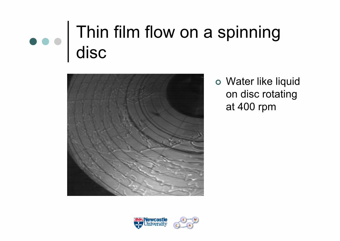
Thin film flow on a spinning disc
Water like liquid on disc rotating at 400 rpm

Wave formation in water-like fluid on rotating disc
(Source: Aoune & Ramshaw, Int. J. Heat & Mass Transfer, 42, 2543-2556 (1999))
Mass flowrate of liquid= 0.013-0.019 kg/s
ω=10 s-1
Spiral waves
ω=20 s-1
Irregular surface ripples
ω=40 s-1
ω=60 s-1

whereQ: feed flowrateν: kinematic viscosity (=η/ρ)ω: rotational speed (= 2πN/60)r: radial distance across disc surface
Parameters of interest in SDR based on centrifugal model
δπ
νω
= 3
2 Q
r2 2⎛⎝⎜
⎞⎠⎟
13
Film thickness:
( )t = 81
Q r rres
2
2 2
13
o iπ νω16
43
43
⎛⎝⎜
⎞⎠⎟ −Residence time:
31
2
42
0. 18
5.12
v⎟⎟⎠
⎞⎜⎜⎝
⎛===
= πνω
νδωγ rQr
dzd
z
rave&Shear rate:
0.0
0.5
1.0
1.5
2.0
2.5
3.0
3.5
4.0
0 200 400 600 800 1000 1200
Disc rotational speed (rpm)
Mea
n re
side
nce
time
in
SDR
, tre
s (s
econ
ds)
0
25
50
75
100
125
150
175
200
225
Mea
n fil
m th
ickn
ess
(m
icro
ns)
5 ml/s
5 ml/s
1 ml/s
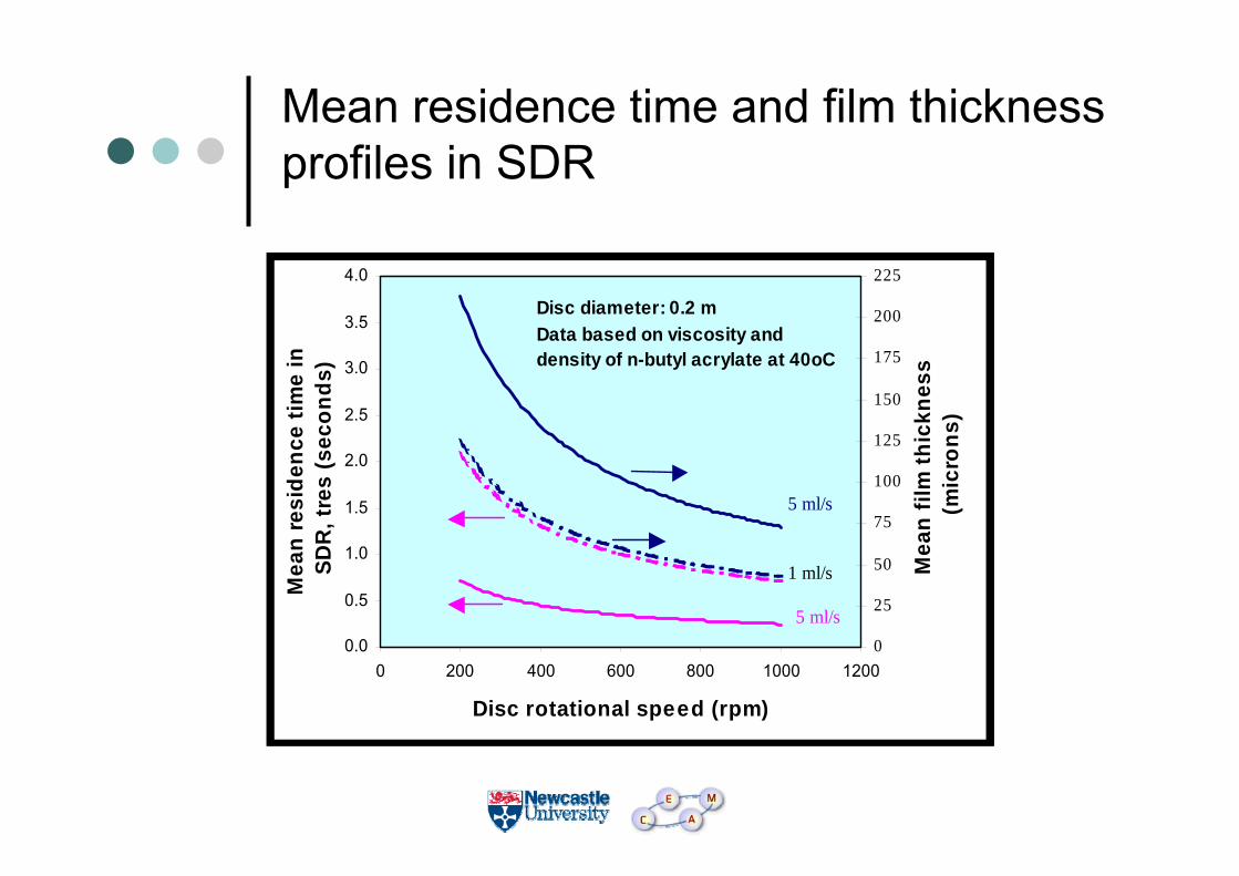
Disc diameter: 0.2 mData based on viscosity and density of n-butyl acrylate at 40oC
Mean residence time and film thickness profiles in SDR
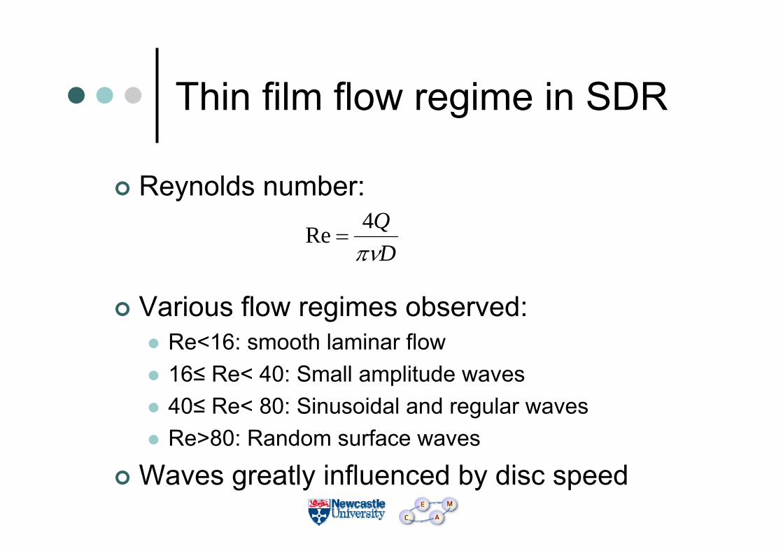
Thin film flow regime in SDR
Reynolds number:
Various flow regimes observed:Re<16: smooth laminar flow16≤ Re< 40: Small amplitude waves40≤ Re< 80: Sinusoidal and regular wavesRe>80: Random surface waves
Waves greatly influenced by disc speed
DQ
πν4Re =

Heat transfer characteristics of thin film
Overall heat transfer coefficient U as high as 4 kW/m2K can be achieved using this system under optimised conditions
Coolant IN
Coolant OUTHollow drive shaft
Internal baffled plate
Process liquid
Disc surface
Internal cooling/heating system in SDR

0
2
4
6
8
10
12
14
16
0 200 400 600 800 1000
Rotational Speed (RPM)
Ave
rage
Hea
t Tra
nsfe
r Coe
ff. (k
W/m
2 K
)
Normal Groove Disc
Metal Sprayed Disc
Smooth Disc
Convective heat transfer characteristics of films on rotating disc surfaces

Effect of rotational speed on local mass transfer coefficients in SDR film
water flowrate: 30 cm3/s smooth disc
(Source: Aoune & Ramshaw, Int. J. Heat & Mass Transfer, 42, 2543-2556 (1999))

Summary of characteristics of thin film flow in SDR
Vigorous mixing characteristics at film surface (waves) and within film (high shear)High heat and mass transfer ratesShort and easily controllable residence times
Extremely short path lengths for efficient UV penetration in photo-reactions
These characteristics make the SDR particularly suitable for reactions that are:
• Highly exothermic• Inherently fast

Reactions/processes for potential SDR application (1)
Inherently fast, highly exothermic reactionsAcid-base neutralisationSulphonationPolymerisations
• Free-radical polymerisations• Chemical initiated• UV-initiated (photopolymerisation)
• Cationic polymerisation• Step-growth polymerisations
• Polyesterifications

Reactions requiring rapid mixingCrystallisations for narrow distribution of particle sizeOrganic, competitive reactions for high selectivity or high yield of desired product
Processes involving heat sensitive materialsPolymer processing at high temperatures Food processing
• Short residence times in SDR gives minimal risk of degradation of product
Reactions/processes for potential SDR application (2)

Case study 1
SDR applications to mixing/mass transfer limited processes in pharmaceutical industry

Rate limiting step: mass transfer across immiscible phases
Batch Process SDR process(4500 rpm)
Conversion 100% 90%Reaction time 1 hr <1 sReaction temp. 0oC 20oCImpurity level 1.5% 0.1%Reactor volume 100 (arbitrary units) 1Production capacity 8 tonnes/yr 8 tonnes/yr
Source: Oxley, P. et al. “Evaluation of spinning disc reactor technology for the manufacture of pharmaceuticals”, Ind. Eng. Chem. Res., 39, 2175-2182 (2000)
Example 1: Phase transfer catalysed reaction- Darzen process

Crystallisation in SDR
Rapid micromixing in the SDR film at high supersaturation
Homogeneous nucleation
Smaller crystal sizes with tighter distribution

Rate limiting step: mixing (hence mass transfer)
Source: Oxley, P. et al. “Evaluation of spinning disc reactor technology for the manufacture of pharmaceuticals”, Ind. Eng. Chem. Res., 39, 2175-2182 (2000)
Example 2: Recrystallisation of an API

Micromixing: SDR vs STR
0.01
0.10
1.00
10.00
100.00
0 1 10 100 1000 10000
Specific Power Dissipation(w/kg)
tm(m
s)
(SDR)Q=1ml/sec
(SDR)Q=3mil/sec
(SDR) Q=5mil/sec
(STR) Injection Point close to impeller
(STR) injection Point away from impeller
tm = 2(ν/ε)0.5 arcsinh (0.05ν/D )
( SDR - Molecular Diffusion Model )
tm = 17.2(ν /ε)½
( STR – Baldyga and Bourne Model)
Case study 2
Application of SDR to organic catalytic reaction using immobilised catalyst

ACatalyst
BA – α-pinene oxide, B – campholenic aldehyde
Process chemistry
Homogeneous catalyst used in current industrial process
Low selectivity due to many side reactions
OH
trans-Pinocarveol
trans-Sobrerol
OH
OH
OH
trans-Carveol
p-Cymene
O
Pinol
O
α-pinene oxide
O
campholenic aldehyde(2,2,3-trimethyl-3-cyclopentenacetaldehyde)
H +H2O/H +
- H2O- 2 H2O
N(Et)2
via cis-Sobrerol
Desired product

8
ReactantCatalyst
Catalyst separation
Product
Current industrial process
Batch process where processing time is typically very high (order of hours)
Need to separate catalyst from product using large amounts of solvent in downstream separation process
Environmental considerations of waste disposal

Objectives of studyEasier catalyst separation
Development of heterogeneous catalysts Immobilisation on reactor surfaceRe-usable
Improve selectivity towards campholenicaldehyde using heterogeneous catalysis and intensified continuous processing
SDR processing:Continuous processProcessing time of the order of secondsCatalyst fixed to rotating surface
Reactant
ProductCatalyst

STR data for benchmarking
0
20
40
60
80
100
0 5 10 15 20 25 30
Reaction Time (min)
Con
vers
ion
(%)
0
20
40
60
80
100
Sele
ctiv
ity (%
)
ConditionsT = 850C
Catalyst: 0.05 mmolg-1 Zn(OTf)2/SiO2
B40% Selectivity
A

Effect of SDR residence time on conversion
70
75
80
85
90
95
100
0 0.2 0.4 0.6 0.8 1 1.2 1.4
Residence Time (s)
Con
vers
ion
(%)
Flow rate = 4 cm /s Flow rate = 5 cm /s Flow rate = 6 cm /s
ConditionsDisc Temperature = 850C
Catalyst: 0.05mmolg-1 Zn-triflate/SiO2
333
M. Vicevic, K.V.K. Boodhoo and K. Scott, Catalytic Isomerisation of alpha-pinene oxide to campholenicaldehyde using silica supported zinc triflate catalysts: II. Performance of immobilised catalysts in a continuous Spinning Disc Reactor. Chem. Eng. J. 133(1-3), 43-57 (2007).

Effect of SDR residence time on selectivity
0
20
40
60
80
100
0 0.2 0.4 0.6 0.8 1 1.2
Residence Time (s)
Sele
ctiv
ity (%
)
Flow rate = 4 cm /s Flow rate = 5 cm /s Flow rate = 6 cm /s
ConditionsDisc Temperature = 850C
Catalyst: 0.05mmolg-1 Zn-triflate/SiO2
333
M. Vicevic, K.V.K. Boodhoo and K. Scott, Catalytic Isomerisation of alpha-pinene oxide to campholenicaldehyde using silica supported zinc triflate catalysts: II. Performance of immobilised catalysts in a continuous Spinning Disc Reactor. Chem. Eng. J. 133(1-3), 43-57 (2007).

Summary of resultsReaction completed within 0.5 s in one SDR pass compared to a timescale of at least 5 min in the batch process
Improved mixing and mass transfer rates in the thin film formed on the rotating disc surface allows the catalytic reaction to proceed at its inherent rate in SDRReaction slower in batch due to mixing limitations
High selectivity in the SDR is encouraged by the short and controllable residence times achieved on the disc
High catalyst activity can be maintained in SDR over long periods of time as shown by re-use studies

Demonstrated benefits of SDRFaster reaction rates
Reduced processing timeImproved product quality
Better control of molecular weight properties in polymerisationsTighter particle size distribution in crystallisations
Improved selectivityLess unwanted by-productsGreener/cleaner technology since reduced downstream processing required
Improved intrinsic safetyLow volumes of materials processed


