1. Introduction 3 2. Compendium of SPIRA-CEL® spiral wound modules and
NADIR® flat sheet membranes 4 3. Product code of SPIRA-CEL® spiral wound modules, type
industry 6 4. State of delivery 8 5. Storage of originally packed modules 9 6. Installation 9 7. Start-up procedure 15 8. Filtration process 17 9. Shut-down and membrane preservation 17 10. Module cleaning 18 11. Life-cycle of the module 19
Appendix 1 Standard dimensions of SPIRA-CEL® spiral wound modules 20
Appendix 3 Quality of rinsing and cleaning water 23
3
1. Introduction This introduction provides solely general information. Please read this instruction manual accurately before handling SPIRA-CEL® spiral wound modules. Follow all the instructions and operate the module only under the required operation conditions. Mishandling can irreversibly depreciate the module performance or even destroy the module. If questions or problems occur, please contact a sales manager of MICRODYN NADIR GmbH.
Please notice: This information is based on our latest state of knowledge and is intended to exhibit a general overview of our products. We reserve the right to make modifications as results of new developments. All existing protective rights are to be considered. The warranty of product quality is given in our General Conditions for Purchase and Sale. Basically we do not take over any warranty for subsequent damages that occur after the application of our products.
NADIR® and SPIRA-CEL® are registered trademarks of MICRODYN-NADIR GmbH.
4
2. Compendium of SPIRA-CEL® spiral wound modules and NADIR® flat sheet membranes
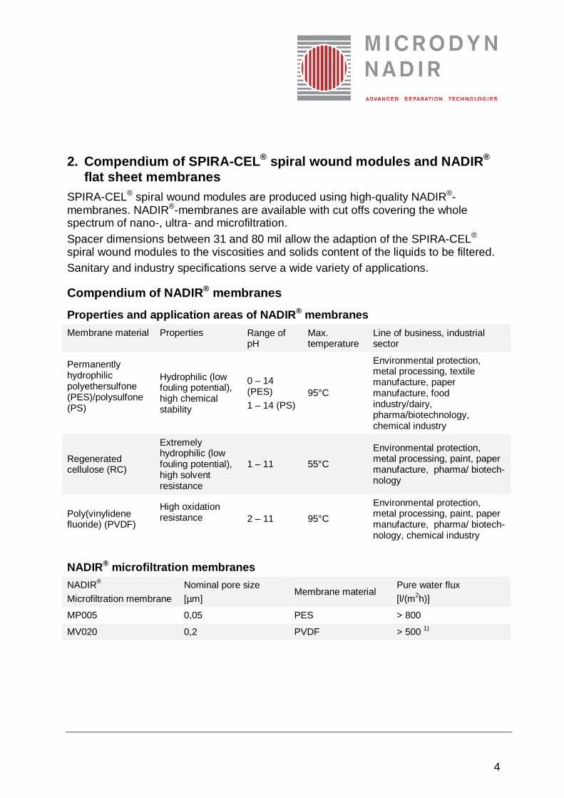
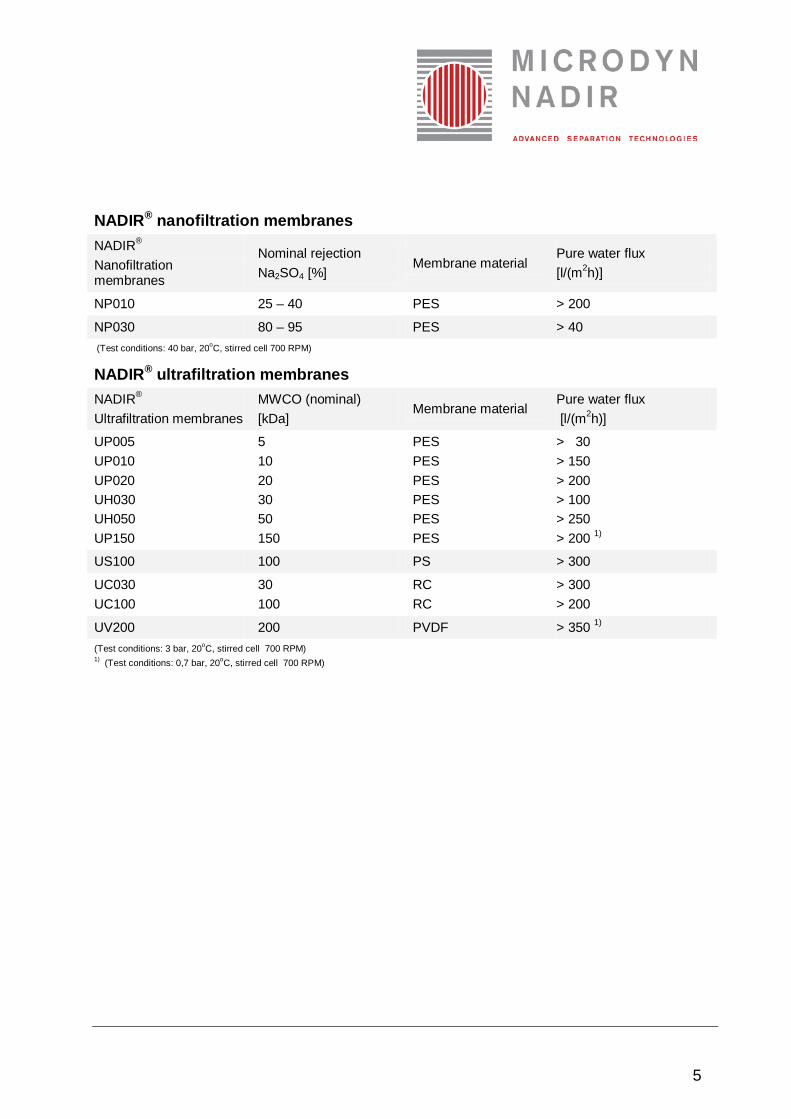
SPIRA-CEL® spiral wound modules are produced using high-quality NADIR®-membranes. NADIR®-membranes are available with cut offs covering the whole spectrum of nano-, ultra- and microfiltration. Spacer dimensions between 31 and 80 mil allow the adaption of the SPIRA-CEL® spiral wound modules to the viscosities and solids content of the liquids to be filtered. Sanitary and industry specifications serve a wide variety of applications.
Compendium of NADIR® membranes
Properties and application areas of NADIR® membranes Membrane material Properties Range of
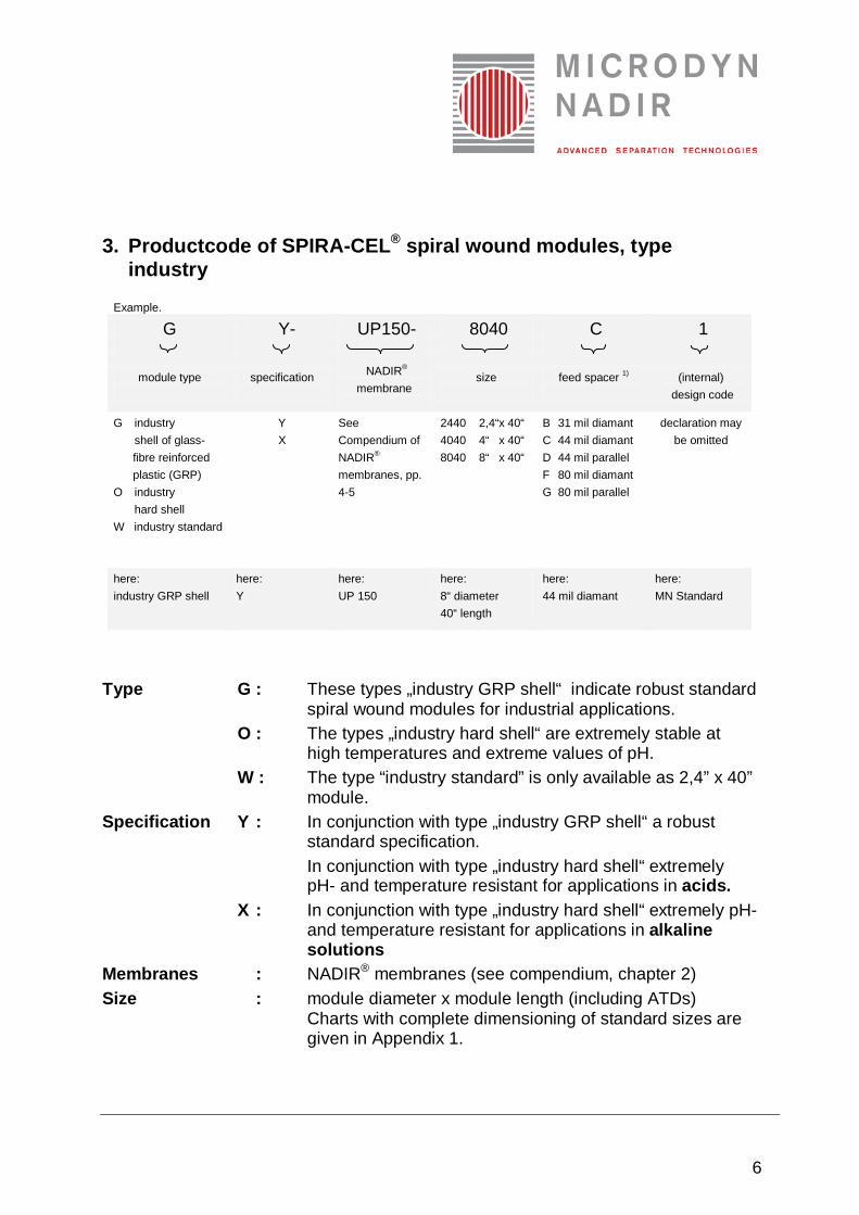
3. Productcode of SPIRA-CEL® spiral wound modules, type industry
Example.
G Y- UP150- 8040 C 1
module type
specification
NADIR® membrane
size
feed spacer 1)
(internal) design code
G industry shell of glass- fibre reinforced plastic (GRP) O industry hard shell W industry standard
Y X
See Compendium of NADIR® membranes, pp. 4-5
2440 2,4“x 40“ 4040 4“ x 40“ 8040 8“ x 40“
B 31 mil diamant C 44 mil diamant D 44 mil parallel F 80 mil diamant G 80 mil parallel
declaration may be omitted
here: industry GRP shell
here: Y
here: UP 150
here: 8“ diameter 40“ length
here: 44 mil diamant
here: MN Standard
Type G : These types „industry GRP shell“ indicate robust standard
spiral wound modules for industrial applications. O : The types „industry hard shell“ are extremely stable at
high temperatures and extreme values of pH. W : The type “industry standard” is only available as 2,4” x 40”
module. Specification Y : In conjunction with type „industry GRP shell“ a robust
standard specification. In conjunction with type „industry hard shell“ extremely pH- and temperature resistant for applications in acids.
X : In conjunction with type „industry hard shell“ extremely pH- and temperature resistant for applications in alkaline solutions
Membranes : NADIR® membranes (see compendium, chapter 2) Size : module diameter x module length (including ATDs)
Charts with complete dimensioning of standard sizes are given in Appendix 1.
7
Feed-Spacers B : 31 mil Diamant C : 44 mil Diamant D : 44 mil Parallel F : 80 mil Diamant G : 80 mil Parallel The choice of spacer type allows the adaption of the free cross section to the viscosity and solid contents of the feed solution.
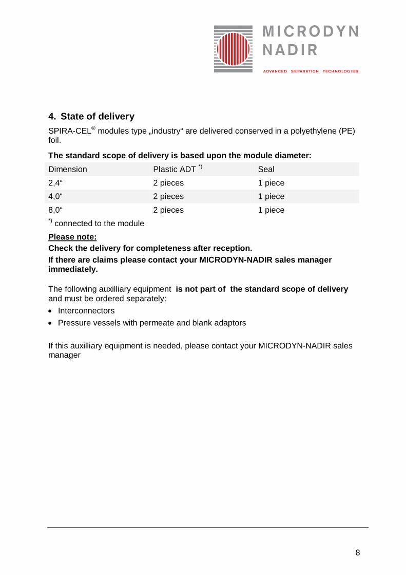
4. State of delivery SPIRA-CEL® modules type „industry“ are delivered conserved in a polyethylene (PE) foil.
The standard scope of delivery is based upon the module diameter: Dimension Plastic ADT *) Seal 2,4“ 2 pieces 1 piece 4,0“ 2 pieces 1 piece 8,0“ 2 pieces 1 piece *) connected to the module Please note: Check the delivery for completeness after reception. If there are claims please contact your MICRODYN-NADIR sales manager immediately.
The following auxilliary equipment is not part of the standard scope of delivery and must be ordered separately: • Interconnectors • Pressure vessels with permeate and blank adaptors If this auxilliary equipment is needed, please contact your MICRODYN-NADIR sales manager
9
5. Storage of originally packed modules If the modules are originally packed, they can be stored over maximal 1 year. • The storage temperature must be kept between 5 °C and 30 °C. • The modules must be kept dry (humidity < 70%). • The modules must not be exposed to direct sunlight permanently. Please note: The module must never be stored at temperatures below 5 °C. After the modules were operated they have to be preserved according to the instructions for membrane preservation after shut-down of the plant (see chapter 9)
6. Installation Please note: Rinse the whole filter plant accurately before installing the module. Make sure that the prefiltration works correctly. Thus the washing of oil residues or metal swarf into the module is inhibited.
Procedure of proper installation a SPIRA-CEL® spiral wound module: In the following the case is described that the permeate is removed from the feed side of the module while the permeate tube is closed by a blank adaptor.
I. Take the module out of the plastic package not till directly before the installation in the pressure vessel. Please make notes which module (see serial number on the package) is installed in which pressure tube. In the following please handle the module with particular care. Check the module for apparent mechanical damages.
10
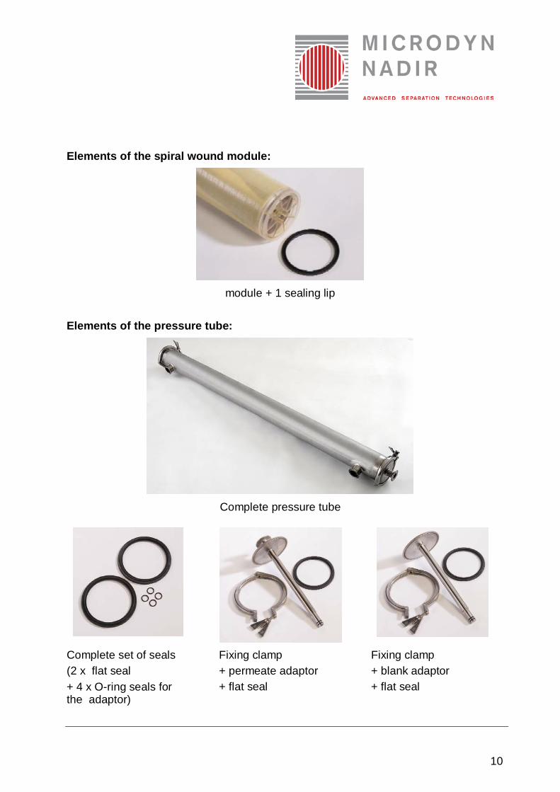
Elements of the spiral wound module:
module + 1 sealing lip
Elements of the pressure tube:
Complete pressure tube
Complete set of seals (2 x flat seal + 4 x O-ring seals for the adaptor)
Fixing clamp + permeate adaptor + flat seal
Fixing clamp + blank adaptor + flat seal
11
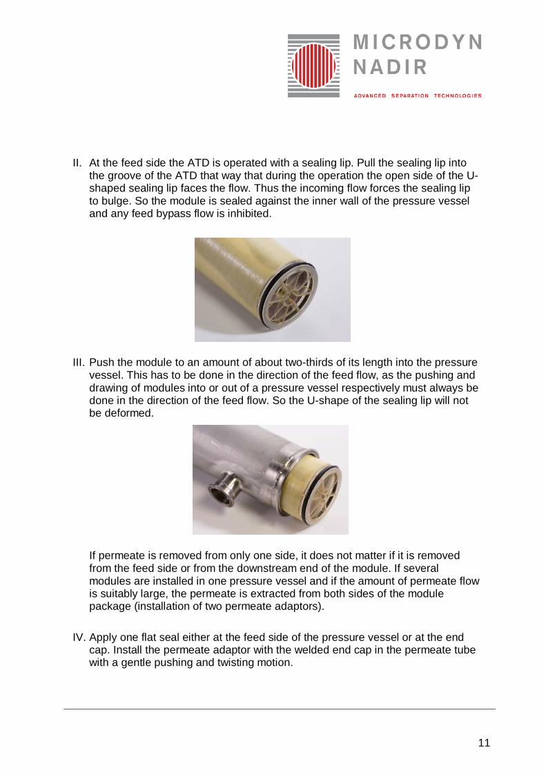
II. At the feed side the ATD is operated with a sealing lip. Pull the sealing lip into
the groove of the ATD that way that during the operation the open side of the U-shaped sealing lip faces the flow. Thus the incoming flow forces the sealing lip to bulge. So the module is sealed against the inner wall of the pressure vessel and any feed bypass flow is inhibited.
III. Push the module to an amount of about two-thirds of its length into the pressure vessel. This has to be done in the direction of the feed flow, as the pushing and drawing of modules into or out of a pressure vessel respectively must always be done in the direction of the feed flow. So the U-shape of the sealing lip will not be deformed.
If permeate is removed from only one side, it does not matter if it is removed from the feed side or from the downstream end of the module. If several modules are installed in one pressure vessel and if the amount of permeate flow is suitably large, the permeate is extracted from both sides of the module package (installation of two permeate adaptors).
IV. Apply one flat seal either at the feed side of the pressure vessel or at the end cap. Install the permeate adaptor with the welded end cap in the permeate tube with a gentle pushing and twisting motion.
12
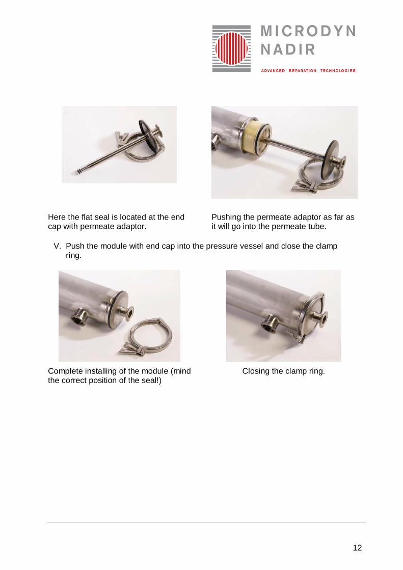
Here the flat seal is located at the end cap with permeate adaptor.
Pushing the permeate adaptor as far as it will go into the permeate tube.
V. Push the module with end cap into the pressure vessel and close the clamp ring.
Complete installing of the module (mind the correct position of the seal!)
Closing the clamp ring.
13
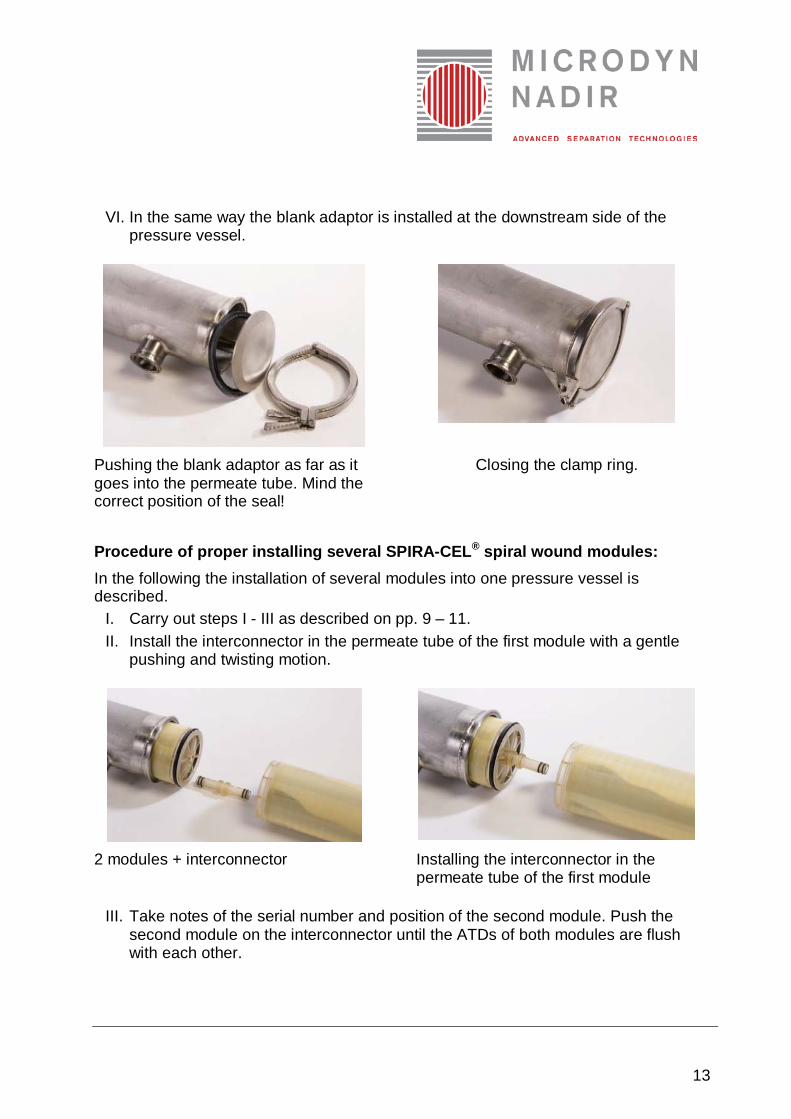
VI. In the same way the blank adaptor is installed at the downstream side of the pressure vessel.
Pushing the blank adaptor as far as it goes into the permeate tube. Mind the correct position of the seal!
Closing the clamp ring.
Procedure of proper installing several SPIRA-CEL® spiral wound modules: In the following the installation of several modules into one pressure vessel is described.
I. Carry out steps I - III as described on pp. 9 – 11. II. Install the interconnector in the permeate tube of the first module with a gentle
pushing and twisting motion.
2 modules + interconnector Installing the interconnector in the
permeate tube of the first module
III. Take notes of the serial number and position of the second module. Push the second module on the interconnector until the ATDs of both modules are flush with each other.
14
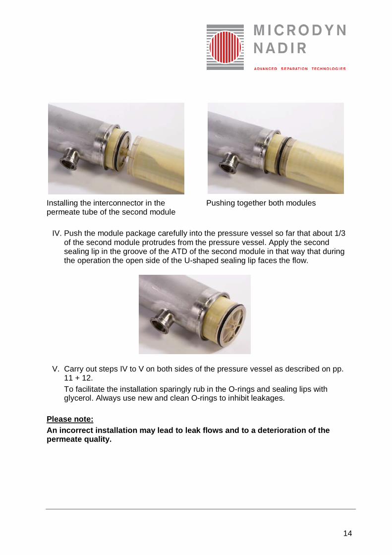
Installing the interconnector in the permeate tube of the second module
Pushing together both modules
IV. Push the module package carefully into the pressure vessel so far that about 1/3 of the second module protrudes from the pressure vessel. Apply the second sealing lip in the groove of the ATD of the second module in that way that during the operation the open side of the U-shaped sealing lip faces the flow.
V. Carry out steps IV to V on both sides of the pressure vessel as described on pp. 11 + 12. To facilitate the installation sparingly rub in the O-rings and sealing lips with glycerol. Always use new and clean O-rings to inhibit leakages.
Please note: An incorrect installation may lead to leak flows and to a deterioration of the permeate quality.
15
7. Start-up procedure This instruction manual is restricted to the appropriate handling of the SPIRA-CEL® spiral wound modules. The safe start-up procedure of the filtration plant is only part of the instruction manual provided by the system manufacturer. Compared to the pumps and pipes the membrane is a relatively susceptible component of the filtration plant. During the planning and operation of the plant one should consider that water hammers, jumps of the solid contents of the feed, strong decrease of the flow rate and temperature shocks are to be inhibited. Please proceed according to the following instructions independently whether the plant is started up to rinse, filtrate or clean. In the state of delivery the membrane is conserved. During the first start-up the modules should be rinsed with water over a period of about 15 min, before the filtration of the feed solution can be started. During the rinsing the preserving agents are dissolved and washed out of the module. The concentrate and permeate produced during this procedure are discarded. The process parameters are the same for the rinsing and the filtration procedure. Please note: The rinsing water must meet certain purity demands (see appendix 3).
For applications with high demands on the purity of the product additional cleaning after rinsing is implicitly recommended, before the filtration of the feed solution is started.
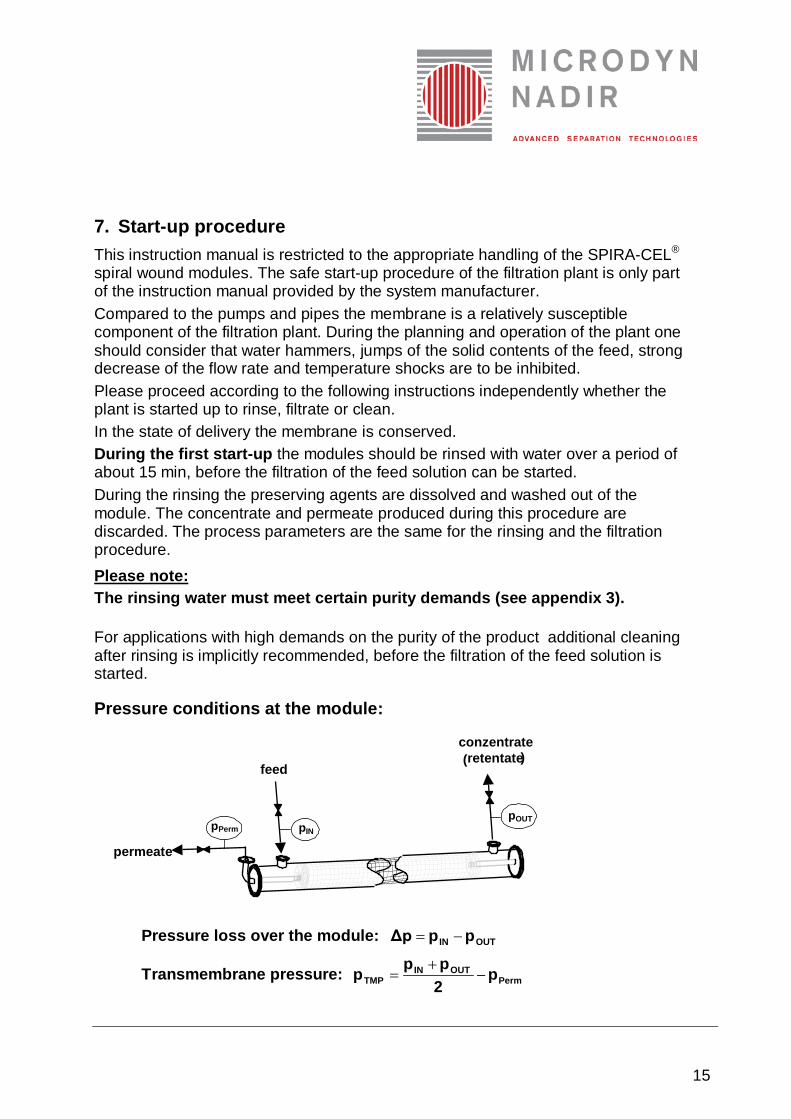
Pressure conditions at the module:
permeate
p OUT p IN p Perm
feed
conzentrate ( retentate )
Pressure loss over the module: OUTIN ppΔp −=
Transmembrane pressure: PermOUTIN
TMP p2ppp −
+=
16
Procedure of proper start-up of SPIRA-CEL® modules: I. Make sure that the permeate discharges unpressurized (open the permeate
valve(s)!). The allowed maximum permeate pressure is 0,35 bar. II. Usually the feed pump is a centrifugal pump. If this is he case, close the feed
valve and open the concentrate outlet (If a positive displacement pump is used, both valves, feed inlet and concentrate outlet, must stay open!).
III. Switch on the feed pump. If the pump is controlled via its rotational speed, choose a low frequency.
IV. Open the feed valve slowly. To inhibit water hammers during the deaering of the system the module is flowed for about 3 min at low pressure.
V. Further opening of the feed valve will increase the flow rate in the module gradually. The transmembrane pressure is adjusted by careful, gradual closing of the concentrate outlet (pressure control valve). • Normally the system offers the opportunity to measure the pressure loss
along the module and the flow rate. Increase the flow velocity gradually. If the pressure loss reaches its limit (see module data sheet, www. microdyn-nadir.de), the flow rate must not be increased any longer. With water (25°C, viscosity 1 mPas) the recommended pressure loss is reached at the flow rate, which is recommended in the data sheet. Please consider that with solutions of higher viscosities the maximum pressure loss is reached at significantly lower flow rates
In any case the concentrate outlet (pressure conrol valve) must be closed thus far that the concentrate pressure at the downstream end always exceeds 0,7 bar. The shut-down procedure is described in detail in chapter 9.
Please note: • Exceeding the maximum pressure loss along the module can lead to the
deterioration of the module. Please mind the corresponding values indicated in the data sheets and consider their temperature dependency.
• Opening the valves too fast can excite water hammers and lead to module damage.
• The permeate outflow must always be unpressurized. The permeate pressure must never exceed the feed side pressure.
• Backflushing is not allowed for this type of module and may lead to its deterioration.
• The module must not be operated in dead-end mode.
• If it is not possible to measure the flow rate, the duty point of the system is only set up by gradual increasing the pressure loss to its recommended value (see module data sheet, www.lenntech.com
17
If questions concerning the start-up procedure occur, please contact your sales manager of MICRODYN-NADIR.
8. Filtration process After rinsing or cleaning the system is switched to the filtration process.
Prefiltration To achieve permanently high permeate fluxes the prefiltration of the feed solution has to be emphasized. Data of an appropriate prefiltration are given in the module data sheets. In particular cases an extensive pretreatment may be necessary. The optimum process parameters can only be obtained by appropriate pilot tests. The point is to find the values for the transmembrane pressure and flow rate which assure permanently optimum permeate flow and permeate quality. The stage of pilot tests is not finished till a stationary operation including cleaning cycles and procedures allows the dimensioning of a large scale plant. The permeate flux increases with increasing transmembrane pressure. Please note that high transmembrane pressures cause the formation of thicker and particularly more dense fouling layers. Thus the permeate flux increases only slowly first and in the long run membrane fouling may even cause a decrease of the permeate flux. Thus moderate transmembrane pressures imply the abdication of top permeate fluxes, but pay off in long-term high and stable permeate fluxes. A high flow rate limits the thickness of the fouling layer and keeps the permeate flux on a high level. But the flow rate itself is limited by the maximum allowable pressure loss of the module! Please mind the corresponding values given in the module data sheets and their temperature dependency!
9. Shut-down and membrane preservation The shut-down procedure should be carried out according to the instructions of the system manufacturer. To assure a proper handling of the modules the following procedure is recommended:
I. Slowly close the feed valve and afterwards slowly close the concentrate outlet (if positive displacement pumps are used, both valves must stay open).
II. Switch off the feed pump. III. Close the permeate outlet not till the feedside is unpressurized (feed pump is
out of action). IV. The modules must always be kept wet, independently whether they stay in the
pressure vessel or are deinstalled.
18
Please note: Drying up the modules lead to their irreversible damage.
V. If the downtime takes between 24 hours up to several months, the modules must be rinsed and cleaned accurately and preserved afterwards to protect them against bacterial fouling. Fill preservation solution into the pressure vessels: • 1,0 % sodium hydrogensulfite (NaHSO3) or • 0,5% formaldehyde (CH2O) By slight short-time flowing of the modules their complete deaering is assured and also the permeate section is completely filled with preservation agent. At any rate the preservation solution should be exchanged every month.
Please note: The demands on the quality of the water used for rinsing and dilution must be fullfilled implicitly (see appendix 3).
10. Module cleaning
A contamination of the membrane surface area can lead to a decrease of the permeate flux. In most instances the fouling layers can be removed from the membrane and the permeate flux can be recuperated. The cleaning procedure must be coordinated to the type of contamination and the resistance of the particular module type.
Please note: • The optimum cleaning strategy should be determined by pilot tests. As
alternative to commercial cleaning agents the pH can be adjusted during the cleaning step by adding caustic soda and citric acid respectively.
• Solely use the cleaning agents that are recommended in appendix 2. If you want to use other cleaning agents, please contact our technical service before.
• During the cleaning procedure the process parameters normally reach the stress limits of the module. Thus each cleaning procedure lowers the life time of the module.
• The demands on the quality of rinsing and thinning water are to be fulfilled implicitly (see appendix 3).
Procedure of proper cleaning the SPIRA-CEL® modules: I. Empty the whole system. II. Wash out feed residues with water until the concentrate is clear. III. Rinse the whole system over a period of 20 min with warm water (maximum
temperature see module data sheet, www.lenntech.com. Concentrate and
19
permeate produced during this procedure are discarded. Empty the whole system.
V. Rinse the system with warm water over a period of 20 min. The concentrate and permeate of this procedure are discarded. Empty the system.
VI. If several cleaning cycles are necessary, repeat the steps IV. and V. in each cycle.
Recommendation of the process parameters during the cleaning: The aim of cleaning is to remove accumulated material from the membrane surface. This is why the cleaning procedure is carried out with high flow rates and low transmembrane pressure. • Pressure at the feed inlet: 1,5 - 2,0 bar • Pressure at the concentrate outlet: 0,7 - 0,9 bar Please note: • The permeate must be extracted at zero pressure. Keep the permeate outlets
always open during the cleaning. • Backflushing is not allowed for this type of module and may lead to its
deterioration. Please contact our technical service, before you use cleaning agents which are not recommended in this instruction manual.
11. Life-cycle of the module The module has reached the end of its life-cycle, if cleaning procedures do not lead to a recuperation of the permeate flux or the separation characteristics any longer. To order new SPIRA-CEL® spiral wound modules please contact your sales manager of MICRODYN-NADIR.
IV. Circulate the cleaning agent within the system. The concentrate and permeate are led back into the cleaning reservoir. The cleaning effect is achieved earlier with warm cleaning agents, but the temperature must not exceed the maximum operation temperature (see module data sheet, www.lenntech.com. After finishing the cleaning cycle the system is emptied and the cleaning agent is discarded.
20
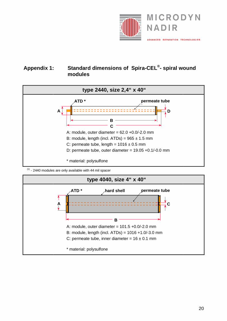
Appendix 1: Standard dimensions of Spira-CEL®- spiral wound modules
type 2440, size 2,4“ x 40“
A
B C
D
ATD * permeate tube *
A: module, outer diameter = 62.0 +0.0/-2.0 mm B: module, length (incl. ATDs) = 965 ± 1.5 mm C: permeate tube, length = 1016 ± 0.5 mm D: permeate tube, outer diameter = 19.05 +0.1/-0.0 mm
* material: polysulfone
(1) - 2440 modules are only available with 44 mil spacer
type 4040, size 4“ x 40“
A
B
C
ATD * permeate tube *
hard shell
A: module, outer diameter = 101.5 +0.0/-2.0 mm B: module, length (incl. ATDs) = 1016 +1.0/-3.0 mm C: permeate tube, inner diameter = 16 ± 0.1 mm
* material: polysulfone
21
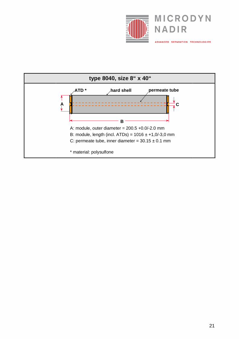
type 8040, size 8“ x 40“
A
B
C
ATD * permeate tube *
hard shell
A: module, outer diameter = 200.5 +0.0/-2.0 mm B: module, length (incl. ATDs) = 1016 ± +1,0/-3,0 mm C: permeate tube, inner diameter = 30.15 ± 0.1 mm
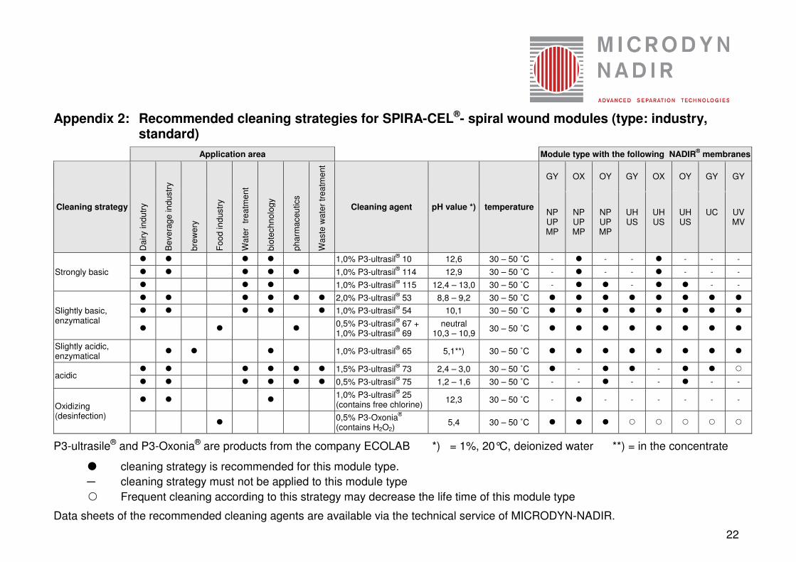
P3-ultrasile® and P3-Oxonia® are products from the company ECOLAB *) = 1%, 20°C, deionized water **) = in the concentrate
� cleaning strategy is recommended for this module type.
─ cleaning strategy must not be applied to this module type
Frequent cleaning according to this strategy may decrease the life time of this module type
Data sheets of the recommended cleaning agents are available via the technical service of MICRODYN-NADIR.
23
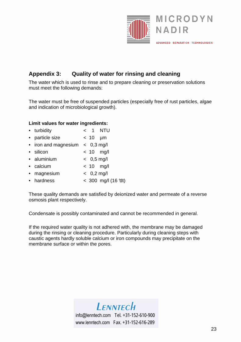
Appendix 3: Quality of water for rinsing and cleaning The water which is used to rinse and to prepare cleaning or preservation solutions must meet the following demands: The water must be free of suspended particles (especially free of rust particles, algae and indication of microbiological growth).
Limit values for water ingredients: • turbidity < 1 NTU
• particle size < 10 µm
• iron and magnesium < 0,3 mg/l
• silicon < 10 mg/l
• aluminium < 0,5 mg/l
• calcium < 10 mg/l
• magnesium < 0,2 mg/l
• hardness < 300 mg/l (16 °dt) These quality demands are satisfied by deionized water and permeate of a reverse osmosis plant respectively. Condensate is possibly contaminated and cannot be recommended in general. If the required water quality is not adhered with, the membrane may be damaged during the rinsing or cleaning procedure. Particularly during cleaning steps with caustic agents hardly soluble calcium or iron compounds may precipitate on the membrane surface or within the pores.