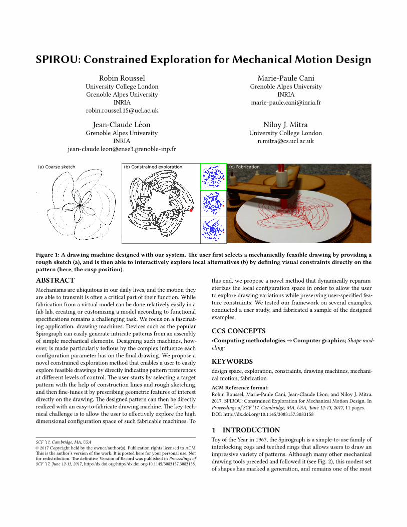
Figure 1: A drawing machine designed with our system. �e user �rst selects a mechanically feasible drawing by providing arough sketch (a), and is then able to interactively explore local alternatives (b) by de�ning visual constraints directly on thepattern (here, the cusp position).
ABSTRACTMechanisms are ubiquitous in our daily lives, and the motion theyare able to transmit is o�en a critical part of their function. Whilefabrication from a virtual model can be done relatively easily in afab lab, creating or customizing a model according to functionalspeci�cations remains a challenging task. We focus on a fascinat-ing application: drawing machines. Devices such as the popularSpirograph can easily generate intricate pa�erns from an assemblyof simple mechanical elements. Designing such machines, how-ever, is made particularly tedious by the complex in�uence eachcon�guration parameter has on the �nal drawing. We propose anovel constrained exploration method that enables a user to easilyexplore feasible drawings by directly indicating pa�ern preferencesat di�erent levels of control. �e user starts by selecting a targetpa�ern with the help of construction lines and rough sketching,and then �ne-tunes it by prescribing geometric features of interestdirectly on the drawing. �e designed pa�ern can then be directlyrealized with an easy-to-fabricate drawing machine. �e key tech-nical challenge is to allow the user to e�ectively explore the highdimensional con�guration space of such fabricable machines. To
this end, we propose a novel method that dynamically reparam-eterizes the local con�guration space in order to allow the userto explore drawing variations while preserving user-speci�ed fea-ture constraints. We tested our framework on several examples,conducted a user study, and fabricated a sample of the designedexamples.
KEYWORDSdesign space, exploration, constraints, drawing machines, mechani-cal motion, fabricationACM Reference format:Robin Roussel, Marie-Paule Cani, Jean-Claude Leon, and Niloy J. Mitra.2017. SPIROU: Constrained Exploration for Mechanical Motion Design. InProceedings of SCF ’17, Cambridge, MA, USA, June 12-13, 2017, 11 pages.DOI: h�p://dx.doi.org/10.1145/3083157.3083158
1 INTRODUCTIONToy of the Year in 1967, the Spirograph is a simple-to-use family ofinterlocking cogs and teethed rings that allows users to draw animpressive variety of pa�erns. Although many other mechanicaldrawing tools preceded and followed it (see Fig. 2), this modest setof shapes has marked a generation, and remains one of the most
SCF ’17, June 12-13, 2017, Cambridge, MA, USA R. Roussel et al.
(a) (b)
(c) (d)
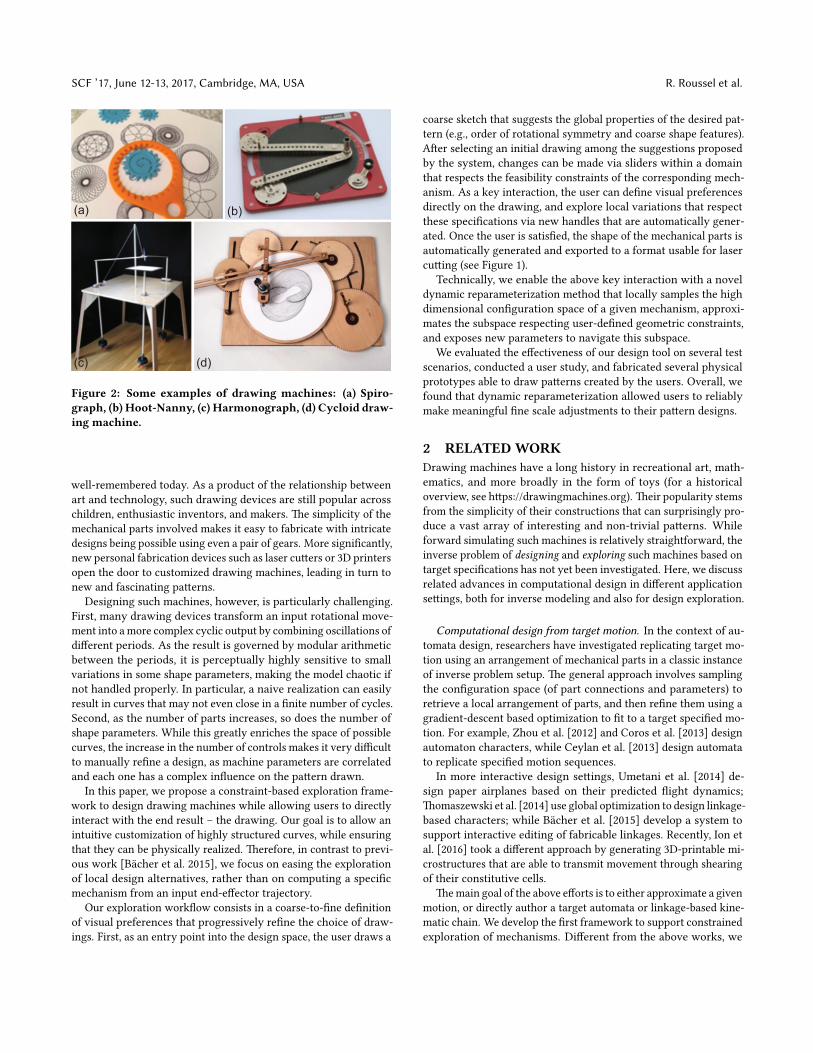
Figure 2: Some examples of drawing machines: (a) Spiro-graph, (b) Hoot-Nanny, (c) Harmonograph, (d) Cycloid draw-ing machine.
well-remembered today. As a product of the relationship betweenart and technology, such drawing devices are still popular acrosschildren, enthusiastic inventors, and makers. �e simplicity of themechanical parts involved makes it easy to fabricate with intricatedesigns being possible using even a pair of gears. More signi�cantly,new personal fabrication devices such as laser cu�ers or 3D printersopen the door to customized drawing machines, leading in turn tonew and fascinating pa�erns.
Designing such machines, however, is particularly challenging.First, many drawing devices transform an input rotational move-ment into a more complex cyclic output by combining oscillations ofdi�erent periods. As the result is governed by modular arithmeticbetween the periods, it is perceptually highly sensitive to smallvariations in some shape parameters, making the model chaotic ifnot handled properly. In particular, a naive realization can easilyresult in curves that may not even close in a �nite number of cycles.Second, as the number of parts increases, so does the number ofshape parameters. While this greatly enriches the space of possiblecurves, the increase in the number of controls makes it very di�cultto manually re�ne a design, as machine parameters are correlatedand each one has a complex in�uence on the pa�ern drawn.
In this paper, we propose a constraint-based exploration frame-work to design drawing machines while allowing users to directlyinteract with the end result – the drawing. Our goal is to allow anintuitive customization of highly structured curves, while ensuringthat they can be physically realized. �erefore, in contrast to previ-ous work [Bacher et al. 2015], we focus on easing the explorationof local design alternatives, rather than on computing a speci�cmechanism from an input end-e�ector trajectory.
Our exploration work�ow consists in a coarse-to-�ne de�nitionof visual preferences that progressively re�ne the choice of draw-ings. First, as an entry point into the design space, the user draws a
coarse sketch that suggests the global properties of the desired pat-tern (e.g., order of rotational symmetry and coarse shape features).A�er selecting an initial drawing among the suggestions proposedby the system, changes can be made via sliders within a domainthat respects the feasibility constraints of the corresponding mech-anism. As a key interaction, the user can de�ne visual preferencesdirectly on the drawing, and explore local variations that respectthese speci�cations via new handles that are automatically gener-ated. Once the user is satis�ed, the shape of the mechanical parts isautomatically generated and exported to a format usable for lasercu�ing (see Figure 1).
Technically, we enable the above key interaction with a noveldynamic reparameterization method that locally samples the highdimensional con�guration space of a given mechanism, approxi-mates the subspace respecting user-de�ned geometric constraints,and exposes new parameters to navigate this subspace.
We evaluated the e�ectiveness of our design tool on several testscenarios, conducted a user study, and fabricated several physicalprototypes able to draw pa�erns created by the users. Overall, wefound that dynamic reparameterization allowed users to reliablymake meaningful �ne scale adjustments to their pa�ern designs.
2 RELATEDWORKDrawing machines have a long history in recreational art, math-ematics, and more broadly in the form of toys (for a historicaloverview, see h�ps://drawingmachines.org). �eir popularity stemsfrom the simplicity of their constructions that can surprisingly pro-duce a vast array of interesting and non-trivial pa�erns. Whileforward simulating such machines is relatively straightforward, theinverse problem of designing and exploring such machines based ontarget speci�cations has not yet been investigated. Here, we discussrelated advances in computational design in di�erent applicationse�ings, both for inverse modeling and also for design exploration.
Computational design from target motion. In the context of au-tomata design, researchers have investigated replicating target mo-tion using an arrangement of mechanical parts in a classic instanceof inverse problem setup. �e general approach involves samplingthe con�guration space (of part connections and parameters) toretrieve a local arrangement of parts, and then re�ne them using agradient-descent based optimization to �t to a target speci�ed mo-tion. For example, Zhou et al. [2012] and Coros et al. [2013] designautomaton characters, while Ceylan et al. [2013] design automatato replicate speci�ed motion sequences.
In more interactive design se�ings, Umetani et al. [2014] de-sign paper airplanes based on their predicted �ight dynamics;�omaszewski et al. [2014] use global optimization to design linkage-based characters; while Bacher et al. [2015] develop a system tosupport interactive editing of fabricable linkages. Recently, Ion etal. [2016] took a di�erent approach by generating 3D-printable mi-crostructures that are able to transmit movement through shearingof their constitutive cells.
�e main goal of the above e�orts is to either approximate a givenmotion, or directly author a target automata or linkage-based kine-matic chain. We develop the �rst framework to support constrainedexploration of mechanisms. Di�erent from the above works, we
SPIROU: Constrained Exploration for Mechanical Motion Design SCF ’17, June 12-13, 2017, Cambridge, MA, USA
allow users to edit the current design (i.e., pa�ern drawn by the ma-chine) by directly interacting with its feature points, thus allowingthem to specify target properties and relations, instead of explicitlyspecifying the �nal pa�ern.
Additionally, in a classical constrained modeling setup, designfrom geometric constraints speci�cations has also been studied.Analyzing and solving such constraints have been tackled by Fudoset al. [1997] in a general se�ing, and Sitharam et al. [2014] in thecontext of mechanisms. �eoretically, even determining parameterbounds characterizing the (constrained) solution domain remains aknown di�cult topic [Barki et al. 2016]. Instead, in this work, weseek a general approximation strategy that support such interactivedesign space exploration for an intuitive work�ow.
Guided exploration of valid designs. In a broader context of de-sign exploration, researchers have studied various properties inorder to optimize a shape based on its intended usage. Examples in-clude shape optimization based on stability considerations [Prevostet al. 2013], or updating object shape for desired moment of iner-tia for object spin [Bacher et al. 2014], adaptively adjusting objectparts for be�er reinforcement and strength [Lu et al. 2014; Zhouet al. 2013], designing hollow chambers for desired acoustic be-havior [Bharaj et al. 2015], zero-waste furniture design [Koo et al.2016], or modeling elastic behavior of foam microstructures for pro-cedurally generating them for target material properties [Martınezet al. 2016].
Closer to our concerns, Umetani et al. [2012] proposed a fur-niture modeling system that actively guides the user to navigatevalid regions of the design space; Bokeloh et al. [2012] and Yumeret al. [2015] developed modeling systems that preserve high-levelstructural and semantic relations in edited 3D models, while Koo etal. [2014] proposed the use of functional speci�cations to map userprescriptions to constrained modeling for ‘works-like’ prototypesof furniture. We have been inspired by the work of Shugrina etal. [2015], who precompute the domain de�ned by fabricability andfunctionality constraints to expose sliders with valid ranges to theuser. In our work, however, additional constraints are de�ned bythe user at runtime directly on the drawing, and new sliders areautomatically generated to explore the resulting constrained space.Recently, Guerrero et al. [2016] proposed e�cient local approxi-mations to enable exploration of pa�ern variations by droppingdi�erent constraints in the input pa�erns. However, the methodis not suitable for variations that are additionally required to bephysically realizable by drawing machines.
As in these works, we aim to ease the exploration of the feasiblespace, but apply this to the new and complex problem of pa�ernstraced out by drawing machines, based on an end e�ector’s motion.
3 OVERVIEWMechanical drawing machines typically are arrangements of cogsand parts, with an end-e�ector that traces out intricate 2D pa�erns.Each such machine physically realizes an algebraic expression con-necting the machine part parameters to the output drawing. �istight coupling between the parameters and the resultant pa�ernvariations makes the designers’ task of exploring the design spacevery challenging. Speci�cally, while on one hand modifying asingle parameter may cause several simultaneous changes (e.g.,
twisting and scaling), on the other hand a single desired changeo�en requires synchronous manipulation of multiple parameters.Our goal is to decorrelate these variations. Rather than trying to�nd the best possible separation (which tends to be subjective orcontext-dependent), our goal is to allow users to de�ne their ownvisual constraints or invariants in the drawing space, so that othervariations can be explored independently.
�ere are two main technical challenges to tackle: �rst, mecha-nisms are o�en described by a relatively high number of parameters(3-8 in our examples), both continuous and discrete, and whosevalid domain is implicitly de�ned by a set of non-linear constraints;second, mapping invariants in the drawing to a corresponding pa-rameter subspace cannot be done analytically in the general case,as the relation between parameter changes and drawing changes isvery complex.
We address these challenges with a two-step work�ow (see Fig. 3).�e �rst step, described in Sec. 4, consists in selecting an appro-priate drawing machine by de�ning global pa�ern characteristicsand providing a coarse sketch. �is step notably allows to assignand �x all discrete parameters. During the second step, describedin Sec. 5, local continuous variations can be explored while dynam-ically specifying visual invariants. Our key contribution is twofold:identify a set of recurring geometric regularities involving relevantfeature points that can be tracked as the drawing changes (Sec. 5.1),and a novel local approximation method that allows to explore thesubspace where such regularities appear (Sec. 5.2).
We evaluate our method in several ways (see Sec. 6). First, wedemonstrate a number of cases where our invariants allow mean-ingful changes in the drawing (Sec. 6.1). Second, we validated thefeasibility of our drawing machines by fabricating several proto-types (Sec. 6.2). Lastly, we conducted a user study to assess theability of invariant-based parameterization to e�ciently help navi-gating the con�guration space (Sec 6.3).
Let us now de�ne the terminology used in the rest of the paper.A mechanical drawing machine comprises of:
• A design space made up of a set of (discrete or continuous)parameters, implicitly bounded by a system of algebraicconstraints (typically nonlinear).
• A simulator that works out the pa�ern by tracing the ma-chine over time. Optionally it outputs a time series of thepositions and orientations of each component, which isuseful for visual inspection. Please note that the simulatorshould be able to automatically determine how long thesimulation should run until the drawing is completed.
• A representation of the associated 3D physical mechanism,possibly with di�erent levels of detail (coarse for visualchecking, and detailed for �le export and fabrication).
Note that we have two levels of representation: the mechanismmodel, characterized by measurable dimensions, and the pa�ern ittraces out, which is visible to the user. In this paper, we will use‘con�guration space’ or ‘parameter space’ when referring to the setof possible combinations of input values that translate into layoutspeci�cations for the mechanism; and use ‘curve space’ or ‘drawingspace’ for the 2D space in which the drawing is realized.
SCF ’17, June 12-13, 2017, Cambridge, MA, USA R. Roussel et al.
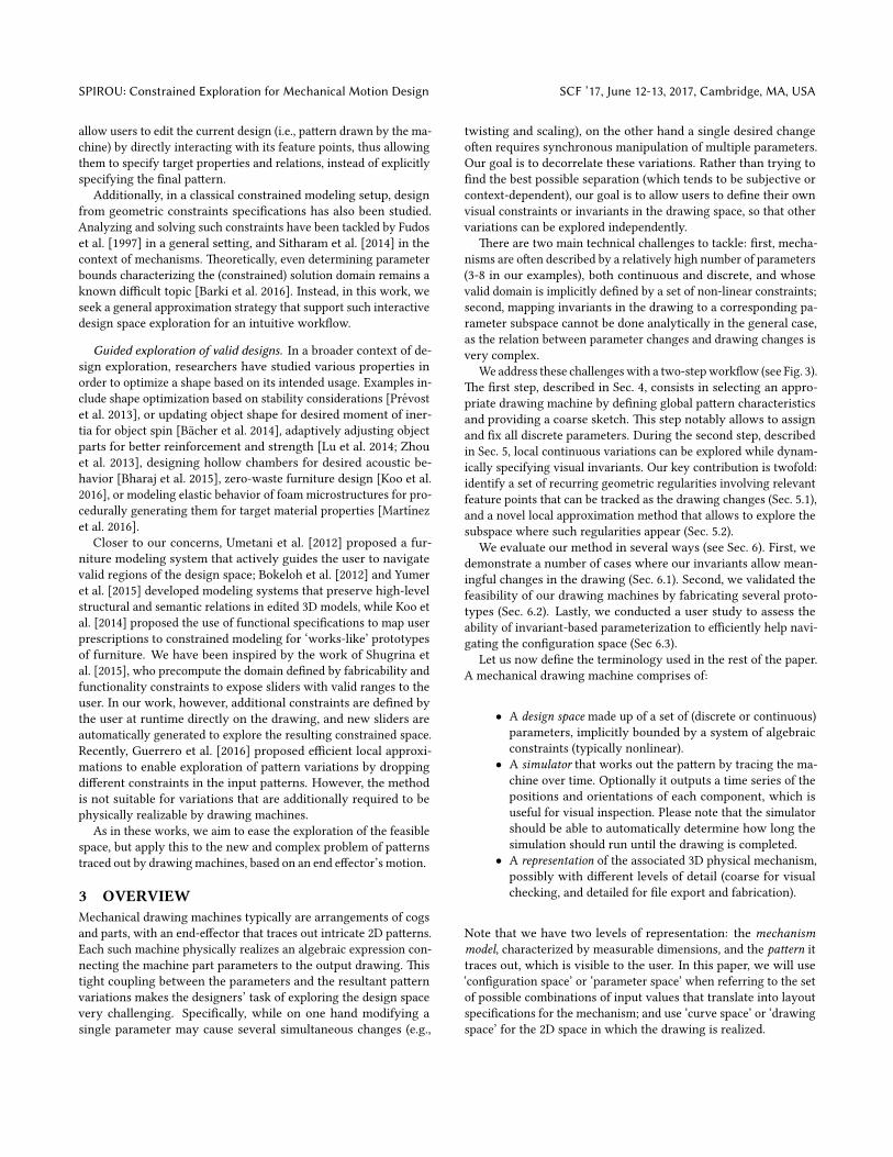
Figure 3: Our design work�ow, separated into the actions performed by the user (top) and the system (bottom). Blue ac-tions (le�) correspond to the high-level sketching phase, while orange actions (right) belong to the constrained explorationphase. Dotted arrows represent transmission of information, and solid arrows represent sequences (straight) or iterations(circular).
4 PATTERN RETRIEVAL�e �rst step of the design work�ow is a sketch-based explorationof the available pa�erns. Essentially we have an inverse problem:�nding the parameter combination such that the simulated motionwill give the feasible drawing closest to the user’s sketch. Since thepa�erns produced by drawing machines are most o�en abstract,intricate, and generally tedious to sketch precisely, we only considerthis step as a way for the user to de�ne global characteristics ofthe drawing. By the properties of gearing, this notably amounts toassigning a value to the discrete parameters of the machine (pleaserefer to the supplementary document for details).
�e user can either input a hand-drawn sketch (Figure 1 (le�)),or roughly sketch the desired curve directly in our system. In thela�er case, she can use construction lines and pre-set the order ofrotational symmetry, having her pen strokes automatically sym-metrized in the other sectors (Figure 4 (top le�)).
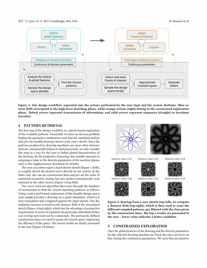
Our curve retrieval algorithm then runs through the databaseof mechanisms to �nd the closest matching pa�erns, as follows.Using a naive grid-based exploration of the feasible design space,each sample provides a drawing via a quick simulation, which is itturn normalized and compared against the input sketch. Our dis-similarity measure is based on the distance �eld of the normalizedsketch (Figure 4 (top right)), which has the advantage of posing fewrequirements in terms of regularity (in particular, individual strokescan overlap and need not be connected). �e previously de�nedconstruction lines are used to prune the search space, improvingthe e�ciency of the query. �e closest results are �nally presentedto the user (Figure 4 bo�om).
Figure 4: Starting from a user sketch (top-le�), we computea distance �eld (top-right), which is then used to score thedi�erent sampled patterns, pre-�ltered with the clues givenby the construction lines. �e top 6 results are presented tothe user – lower value indicates a better candidate.
5 CONSTRAINED EXPLORATIONOnce the global features of the drawing and the discrete parametersfor the selected drawing machine are �xed, the user can focus on�ne tuning the continuous parameters. We note that an intuitive
SPIROU: Constrained Exploration for Mechanical Motion Design SCF ’17, June 12-13, 2017, Cambridge, MA, USA
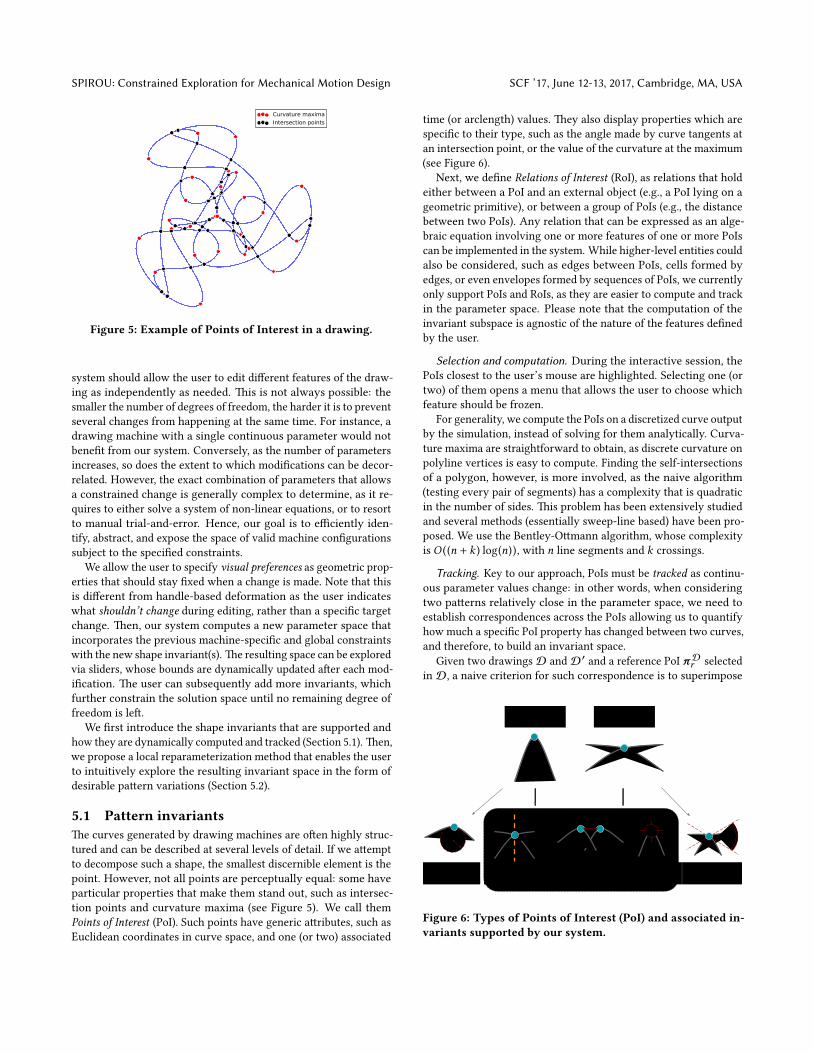
Figure 5: Example of Points of Interest in a drawing.
system should allow the user to edit di�erent features of the draw-ing as independently as needed. �is is not always possible: thesmaller the number of degrees of freedom, the harder it is to preventseveral changes from happening at the same time. For instance, adrawing machine with a single continuous parameter would notbene�t from our system. Conversely, as the number of parametersincreases, so does the extent to which modi�cations can be decor-related. However, the exact combination of parameters that allowsa constrained change is generally complex to determine, as it re-quires to either solve a system of non-linear equations, or to resortto manual trial-and-error. Hence, our goal is to e�ciently iden-tify, abstract, and expose the space of valid machine con�gurationssubject to the speci�ed constraints.
We allow the user to specify visual preferences as geometric prop-erties that should stay �xed when a change is made. Note that thisis di�erent from handle-based deformation as the user indicateswhat shouldn’t change during editing, rather than a speci�c targetchange. �en, our system computes a new parameter space thatincorporates the previous machine-speci�c and global constraintswith the new shape invariant(s). �e resulting space can be exploredvia sliders, whose bounds are dynamically updated a�er each mod-i�cation. �e user can subsequently add more invariants, whichfurther constrain the solution space until no remaining degree offreedom is le�.
We �rst introduce the shape invariants that are supported andhow they are dynamically computed and tracked (Section 5.1). �en,we propose a local reparameterization method that enables the userto intuitively explore the resulting invariant space in the form ofdesirable pa�ern variations (Section 5.2).
5.1 Pattern invariants�e curves generated by drawing machines are o�en highly struc-tured and can be described at several levels of detail. If we a�emptto decompose such a shape, the smallest discernible element is thepoint. However, not all points are perceptually equal: some haveparticular properties that make them stand out, such as intersec-tion points and curvature maxima (see Figure 5). We call themPoints of Interest (PoI). Such points have generic a�ributes, such asEuclidean coordinates in curve space, and one (or two) associated
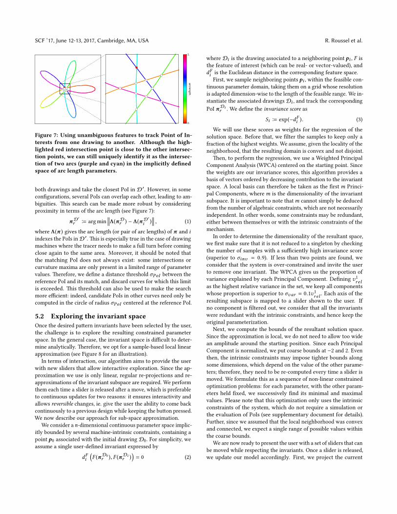
time (or arclength) values. �ey also display properties which arespeci�c to their type, such as the angle made by curve tangents atan intersection point, or the value of the curvature at the maximum(see Figure 6).
Next, we de�ne Relations of Interest (RoI), as relations that holdeither between a PoI and an external object (e.g., a PoI lying on ageometric primitive), or between a group of PoIs (e.g., the distancebetween two PoIs). Any relation that can be expressed as an alge-braic equation involving one or more features of one or more PoIscan be implemented in the system. While higher-level entities couldalso be considered, such as edges between PoIs, cells formed byedges, or even envelopes formed by sequences of PoIs, we currentlyonly support PoIs and RoIs, as they are easier to compute and trackin the parameter space. Please note that the computation of theinvariant subspace is agnostic of the nature of the features de�nedby the user.
Selection and computation. During the interactive session, thePoIs closest to the user’s mouse are highlighted. Selecting one (ortwo) of them opens a menu that allows the user to choose whichfeature should be frozen.
For generality, we compute the PoIs on a discretized curve outputby the simulation, instead of solving for them analytically. Curva-ture maxima are straightforward to obtain, as discrete curvature onpolyline vertices is easy to compute. Finding the self-intersectionsof a polygon, however, is more involved, as the naive algorithm(testing every pair of segments) has a complexity that is quadraticin the number of sides. �is problem has been extensively studiedand several methods (essentially sweep-line based) have been pro-posed. We use the Bentley-O�mann algorithm, whose complexityis O ((n + k ) log(n)), with n line segments and k crossings.
Tracking. Key to our approach, PoIs must be tracked as continu-ous parameter values change: in other words, when consideringtwo pa�erns relatively close in the parameter space, we need toestablish correspondences across the PoIs allowing us to quantifyhow much a speci�c PoI property has changed between two curves,and therefore, to build an invariant space.
Given two drawings D and D ′ and a reference PoI πDr selectedin D, a naive criterion for such correspondence is to superimpose
Curvature maximum Intersection
Radius of curvature Lying on a line Position Intersection
angleDistance
Figure 6: Types of Points of Interest (PoI) and associated in-variants supported by our system.
SCF ’17, June 12-13, 2017, Cambridge, MA, USA R. Roussel et al.
Figure 7: Using unambiguous features to track Point of In-terests from one drawing to another. Although the high-lighted red intersection point is close to the other intersec-tion points, we can still uniquely identify it as the intersec-tion of two arcs (purple and cyan) in the implicitly de�nedspace of arc length parameters.
both drawings and take the closest PoI in D ′. However, in somecon�gurations, several PoIs can overlap each other, leading to am-biguities. �is search can be made more robust by consideringproximity in terms of the arc length (see Figure 7):
πD′
r B arg min Λ(πDr ) − Λ(πD
′
i ) , (1)
where Λ(π ) gives the arc length (or pair of arc lengths) of π and iindexes the PoIs inD ′. �is is especially true in the case of drawingmachines where the tracer needs to make a full turn before comingclose again to the same area. Moreover, it should be noted thatthe matching PoI does not always exist: some intersections orcurvature maxima are only present in a limited range of parametervalues. �erefore, we de�ne a distance threshold σPoI between thereference PoI and its match, and discard curves for which this limitis exceeded. �is threshold can also be used to make the searchmore e�cient: indeed, candidate PoIs in other curves need only becomputed in the circle of radius σPoI centered at the reference PoI.
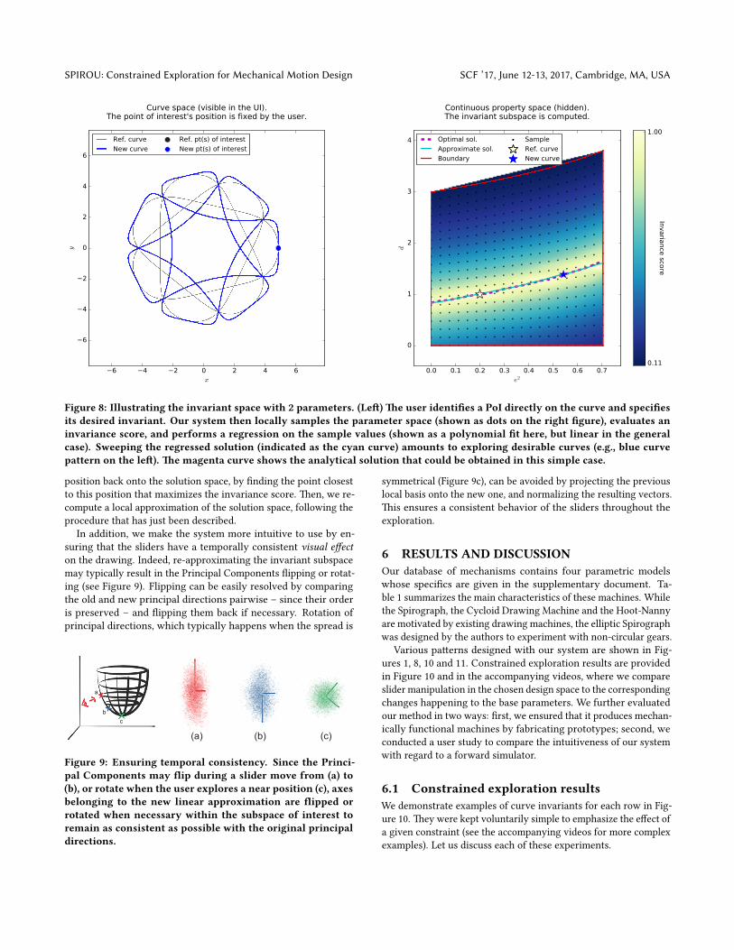
5.2 Exploring the invariant spaceOnce the desired pa�ern invariants have been selected by the user,the challenge is to explore the resulting constrained parameterspace. In the general case, the invariant space is di�cult to deter-mine analytically. �erefore, we opt for a sample-based local linearapproximation (see Figure 8 for an illustration).
In terms of interaction, our algorithm aims to provide the userwith new sliders that allow interactive exploration. Since the ap-proximation we use is only linear, regular re-projections and re-approximations of the invariant subspace are required. We performthem each time a slider is released a�er a move, which is preferableto continuous updates for two reasons: it ensures interactivity andallows reversible changes, ie. give the user the ability to come backcontinuously to a previous design while keeping the bu�on pressed.We now describe our approach for sub-space approximation.
We consider a n-dimensional continuous parameter space implic-itly bounded by several machine-intrinsic constraints, containing apoint p0 associated with the initial drawing D0. For simplicity, weassume a single user-de�ned invariant expressed by
dFi(F (πD0
r ), F (πDir ))= 0 (2)
where Di is the drawing associated to a neighboring point pi , F isthe feature of interest (which can be real- or vector-valued), anddFi is the Euclidean distance in the corresponding feature space.
First, we sample neighboring points pi , within the feasible con-tinuous parameter domain, taking them on a grid whose resolutionis adapted dimension-wise to the length of the feasible range. We in-stantiate the associated drawings Di , and track the correspondingPoI πDi
r . We de�ne the invariance score as
Si B exp(−dFi ). (3)
We will use these scores as weights for the regression of thesolution space. Before that, we �lter the samples to keep only afraction of the highest weights. We assume, given the locality of theneighborhood, that the resulting domain is convex and not disjoint.
�en, to perform the regression, we use a Weighted PrincipalComponent Analysis (WPCA) centered on the starting point. Sincethe weights are our invariance scores, this algorithm provides abasis of vectors ordered by decreasing contribution to the invariantspace. A local basis can therefore be taken as the �rst m Princi-pal Components, where m is the dimensionality of the invariantsubspace. It is important to note that m cannot simply be deducedfrom the number of algebraic constraints, which are not necessarilyindependent. In other words, some constraints may be redundant,either between themselves or with the intrinsic constraints of themechanism.
In order to determine the dimensionality of the resultant space,we �rst make sure that it is not reduced to a singleton by checkingthe number of samples with a su�ciently high invariance score(superior to σinv = 0.9). If less than two points are found, weconsider that the system is over-constrained and invite the userto remove one invariant. �e WPCA gives us the proportion ofvariance explained by each Principal Component. De�ning v1
r elas the highest relative variance in the set, we keep all componentswhose proportion is superior to σvar = 0.1v1
r el . Each axis of theresulting subspace is mapped to a slider shown to the user. Ifno component is �ltered out, we consider that all the invariantswere redundant with the intrinsic constraints, and hence keep theoriginal parameterization.
Next, we compute the bounds of the resultant solution space.Since the approximation is local, we do not need to allow too widean amplitude around the starting position. Since each PrincipalComponent is normalized, we put coarse bounds at −2 and 2. Eventhen, the intrinsic constraints may impose tighter bounds alongsome dimensions, which depend on the value of the other parame-ters; therefore, they need to be re-computed every time a slider ismoved. We formulate this as a sequence of non-linear constrainedoptimization problems: for each parameter, with the other param-eters held �xed, we successively �nd its minimal and maximalvalues. Please note that this optimization only uses the intrinsicconstraints of the system, which do not require a simulation orthe evaluation of PoIs (see supplementary document for details).Further, since we assumed that the local neighborhood was convexand connected, we expect a single range of possible values withinthe coarse bounds.
We are now ready to present the user with a set of sliders that canbe moved while respecting the invariants. Once a slider is released,we update our model accordingly. First, we project the current
SPIROU: Constrained Exploration for Mechanical Motion Design SCF ’17, June 12-13, 2017, Cambridge, MA, USA
Figure 8: Illustrating the invariant space with 2 parameters. (Le�) �e user identi�es a PoI directly on the curve and speci�esits desired invariant. Our system then locally samples the parameter space (shown as dots on the right �gure), evaluates aninvariance score, and performs a regression on the sample values (shown as a polynomial �t here, but linear in the generalcase). Sweeping the regressed solution (indicated as the cyan curve) amounts to exploring desirable curves (e.g., blue curvepattern on the le�). �e magenta curve shows the analytical solution that could be obtained in this simple case.
position back onto the solution space, by �nding the point closestto this position that maximizes the invariance score. �en, we re-compute a local approximation of the solution space, following theprocedure that has just been described.
In addition, we make the system more intuitive to use by en-suring that the sliders have a temporally consistent visual e�ecton the drawing. Indeed, re-approximating the invariant subspacemay typically result in the Principal Components �ipping or rotat-ing (see Figure 9). Flipping can be easily resolved by comparingthe old and new principal directions pairwise – since their orderis preserved – and �ipping them back if necessary. Rotation ofprincipal directions, which typically happens when the spread is
(a) (b) (c)
a
bc
Figure 9: Ensuring temporal consistency. Since the Princi-pal Components may �ip during a slider move from (a) to(b), or rotate when the user explores a near position (c), axesbelonging to the new linear approximation are �ipped orrotated when necessary within the subspace of interest toremain as consistent as possible with the original principaldirections.
symmetrical (Figure 9c), can be avoided by projecting the previouslocal basis onto the new one, and normalizing the resulting vectors.�is ensures a consistent behavior of the sliders throughout theexploration.
6 RESULTS AND DISCUSSIONOur database of mechanisms contains four parametric modelswhose speci�cs are given in the supplementary document. Ta-ble 1 summarizes the main characteristics of these machines. Whilethe Spirograph, the Cycloid Drawing Machine and the Hoot-Nannyare motivated by existing drawing machines, the elliptic Spirographwas designed by the authors to experiment with non-circular gears.
Various pa�erns designed with our system are shown in Fig-ures 1, 8, 10 and 11. Constrained exploration results are providedin Figure 10 and in the accompanying videos, where we compareslider manipulation in the chosen design space to the correspondingchanges happening to the base parameters. We further evaluatedour method in two ways: �rst, we ensured that it produces mechan-ically functional machines by fabricating prototypes; second, weconducted a user study to compare the intuitiveness of our systemwith regard to a forward simulator.
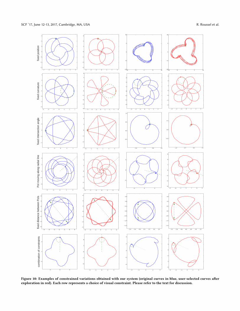
6.1 Constrained exploration resultsWe demonstrate examples of curve invariants for each row in Fig-ure 10. �ey were kept voluntarily simple to emphasize the e�ect ofa given constraint (see the accompanying videos for more complexexamples). Let us discuss each of these experiments.
SCF ’17, June 12-13, 2017, Cambridge, MA, USA R. Roussel et al.
fixed
pos
ition
fixed
cur
vatu
refix
ed in
ters
ectio
n an
gle
PoI
mov
ing
alon
g ra
dial
line
fixed
dis
tanc
e be
twee
n P
oIs
com
bina
tion
of c
onst
rain
ts
4 2 0 2 4
4
2
0
2
4
3 2 1 0 1 2
3
2
1
0
1
2
Figure 10: Examples of constrained variations obtained with our system (original curves in blue, user-selected curves a�erexploration in red). Each row represents a choice of visual constraint. Please refer to the text for discussion.
SPIROU: Constrained Exploration for Mechanical Motion Design SCF ’17, June 12-13, 2017, Cambridge, MA, USA
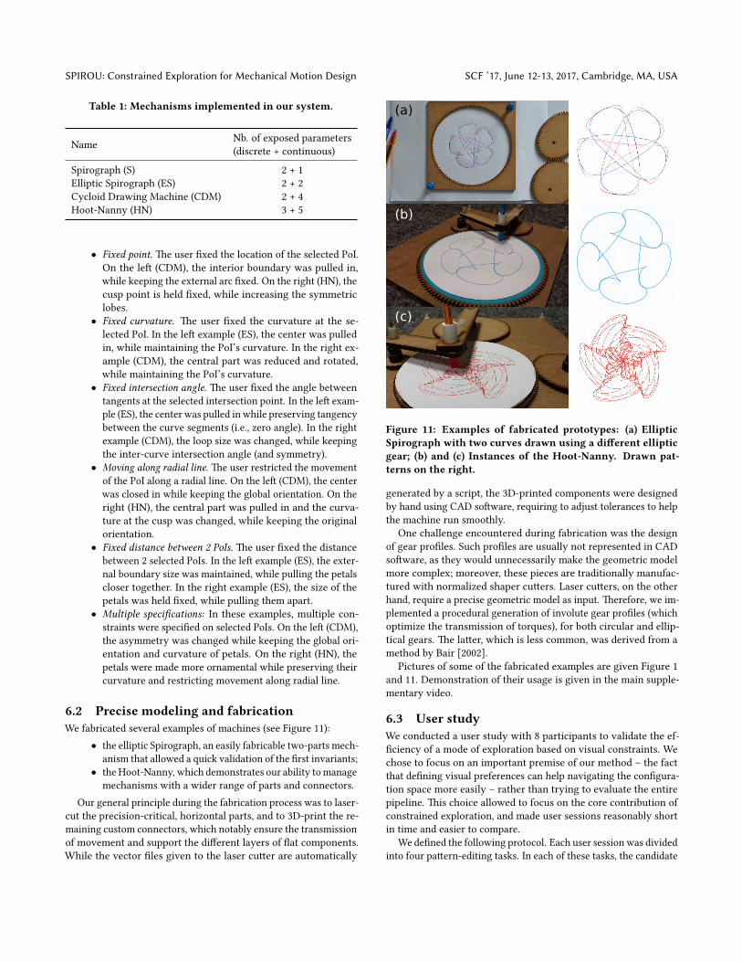
Table 1: Mechanisms implemented in our system.
Name Nb. of exposed parameters(discrete + continuous)
• Fixed point. �e user �xed the location of the selected PoI.On the le� (CDM), the interior boundary was pulled in,while keeping the external arc �xed. On the right (HN), thecusp point is held �xed, while increasing the symmetriclobes.
• Fixed curvature. �e user �xed the curvature at the se-lected PoI. In the le� example (ES), the center was pulledin, while maintaining the PoI’s curvature. In the right ex-ample (CDM), the central part was reduced and rotated,while maintaining the PoI’s curvature.
• Fixed intersection angle. �e user �xed the angle betweentangents at the selected intersection point. In the le� exam-ple (ES), the center was pulled in while preserving tangencybetween the curve segments (i.e., zero angle). In the rightexample (CDM), the loop size was changed, while keepingthe inter-curve intersection angle (and symmetry).
• Moving along radial line. �e user restricted the movementof the PoI along a radial line. On the le� (CDM), the centerwas closed in while keeping the global orientation. On theright (HN), the central part was pulled in and the curva-ture at the cusp was changed, while keeping the originalorientation.
• Fixed distance between 2 PoIs. �e user �xed the distancebetween 2 selected PoIs. In the le� example (ES), the exter-nal boundary size was maintained, while pulling the petalscloser together. In the right example (ES), the size of thepetals was held �xed, while pulling them apart.
• Multiple speci�cations: In these examples, multiple con-straints were speci�ed on selected PoIs. On the le� (CDM),the asymmetry was changed while keeping the global ori-entation and curvature of petals. On the right (HN), thepetals were made more ornamental while preserving theircurvature and restricting movement along radial line.
6.2 Precise modeling and fabricationWe fabricated several examples of machines (see Figure 11):
• the elliptic Spirograph, an easily fabricable two-parts mech-anism that allowed a quick validation of the �rst invariants;
• the Hoot-Nanny, which demonstrates our ability to managemechanisms with a wider range of parts and connectors.
Our general principle during the fabrication process was to laser-cut the precision-critical, horizontal parts, and to 3D-print the re-maining custom connectors, which notably ensure the transmissionof movement and support the di�erent layers of �at components.While the vector �les given to the laser cu�er are automatically
(a)
(b)
(c)
Figure 11: Examples of fabricated prototypes: (a) EllipticSpirograph with two curves drawn using a di�erent ellipticgear; (b) and (c) Instances of the Hoot-Nanny. Drawn pat-terns on the right.
generated by a script, the 3D-printed components were designedby hand using CAD so�ware, requiring to adjust tolerances to helpthe machine run smoothly.
One challenge encountered during fabrication was the designof gear pro�les. Such pro�les are usually not represented in CADso�ware, as they would unnecessarily make the geometric modelmore complex; moreover, these pieces are traditionally manufac-tured with normalized shaper cu�ers. Laser cu�ers, on the otherhand, require a precise geometric model as input. �erefore, we im-plemented a procedural generation of involute gear pro�les (whichoptimize the transmission of torques), for both circular and ellip-tical gears. �e la�er, which is less common, was derived from amethod by Bair [2002].
Pictures of some of the fabricated examples are given Figure 1and 11. Demonstration of their usage is given in the main supple-mentary video.
6.3 User studyWe conducted a user study with 8 participants to validate the ef-�ciency of a mode of exploration based on visual constraints. Wechose to focus on an important premise of our method – the factthat de�ning visual preferences can help navigating the con�gura-tion space more easily – rather than trying to evaluate the entirepipeline. �is choice allowed to focus on the core contribution ofconstrained exploration, and made user sessions reasonably shortin time and easier to compare.
We de�ned the following protocol. Each user session was dividedinto four pa�ern-editing tasks. In each of these tasks, the candidate
SCF ’17, June 12-13, 2017, Cambridge, MA, USA R. Roussel et al.
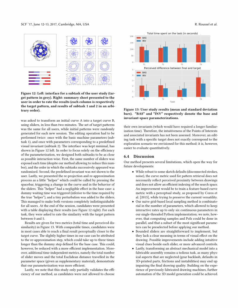
Figure 12: Le�: interface for a subtask of the user study (tar-get pattern in grey). Right: summary sheet presented to theuser in order to rate the results (each column is respectivelythe target pattern, and results of subtask 1 and 2 in an arbi-trary order).
was asked to transform an initial curve A into a target curve B,using sliders, in less than two minutes. �e set of target pa�ernswas the same for all users, while initial pa�erns were randomlygenerated for each new session. �e editing operation had to beperformed twice: once with the basic machine parameters (sub-task 1), and once with parameters corresponding to a prede�nedvisual invariant (subtask 2). �e interface was kept minimal, hasshown in Figure 12 le�. In order to focus solely on the e�ciencyof the parameterization, we designed both subtasks to be as closeas possible interaction-wise. First, the same number of sliders wasexposed each time (despite our method allowing to reduce this num-ber), and the order in which the subtasks successively appeared wasrandomized. Second, the prede�ned invariant was not shown to theuser. Lastly, we presented the re-projection and re-approximationprocess as a li�le “helper” which could be called by pressing thespacebar, triggering a change in the curve and in the behavior ofthe sliders. �is “helper” had a negligible e�ect in the base case: adummy waiting time was triggered (inferior to the time required bythe true “helper”), and a tiny perturbation was added to the sliders.�is managed to make both versions completely indistinguishablefor all users. At the end of the session, candidates were presentedwith a table displaying their results (see Figure 12 right). For eachtask, they were asked to rate the similarity with the target pa�ernbetween 0 and 5.
Results are given for two metrics (total time and perceived dis-similarity) in Figure 13. With comparable times, candidates werein most cases able to reach a �nal result perceptually closer to thetarget curve. �e slightly higher times in our case can be a�ributedto the re-approximation step, which could take up to three timeslonger than the dummy step de�ned for the base case. �is could,however, be reduced with a more e�cient implementation. More-over, additional time-independent metrics, namely the total numberof slider moves and the total Euclidean distance travelled in theparameter space (given as supplementary material), demonstratethat our parameterization was more e�cient.
Lastly, we note that this study only partially validates the e�-ciency of our method, as candidates were not allowed to choose
Figure 13: User study results (mean and standard deviationbars). “BAS” and “INV” respectively denote the base andinvariant-space parameterizations.
their own invariants (which would have required a longer familiar-ization time). �erefore, the intuitiveness of the Points of Interestsand associated invariants has not been assessed. Moreover, an edit-ing task with a speci�c target does not exactly correspond to theexploration scenario we envisioned for this method; it is, however,easier to evaluate quantitatively.
6.4 DiscussionOur method presents several limitations, which open the way forfuture developments:
• While robust to some sketch defaults (disconnected strokes,noise), the curve metric used for pa�ern retrieval does notnecessarily re�ect perceived proximity between drawingsand does not allow an e�cient indexing of the search space.An improvement would be to train a feature-based curvemetric with a perceptual study, as proposed by Coros etal. [2013], while trying to preserve the current versatility.
• Our naive grid-based local sampling method is combinato-rial in the number of parameters, which allowed to keepinteractive rates up to only six continuous parameters inour single-threaded Python implementation; we note, how-ever, that computing samples and PoIs could be done inparallel, and that a subset of the most signi�cant parame-ters can be preselected before applying our method.
• Bounded sliders are straightforward to implement, butthey lack a clear meaning in terms of visual e�ect on thedrawing. Possible improvements include adding intuitivevisual clues beside each slider, or more advanced controls.
• Lastly, transforming an abstract mechanical model into afabricable assembly remains a tedious task, as many phys-ical aspects that are neglected (gear backlash, defaults in3D-printed parts, frictions and instabilities) may end upimpairing the �nal drawing quality. Building on the expe-rience of previously fabricated drawing machines, furtherautomation of the 3D model generation could be achieved.
SPIROU: Constrained Exploration for Mechanical Motion Design SCF ’17, June 12-13, 2017, Cambridge, MA, USA
�e speci�c application domain presented in this paper, whileinteresting from an educational and artistic point of view, is ar-guably limited in terms of practical value. �e core concepts of ourmethod, however, are not bound to drawing machines. �ey shouldbe applicable to a wider range of generative design systems with aset of continuous and discrete parameters as input, assuming accessto a reasonably fast forward simulation (or procedural generation)leading to an output having a measurable (and desirable) regular-ity. For instance, dynamic reparameterization could be used tointeractively constrain the motion of mechanical characters [Coroset al. 2013] as well as more generic linkages [Bacher et al. 2015]to explore the di�erent ways an end-e�ector can reach a speci�cpoint in space, such as a character kicking a ball or laying a kiss.Designing cyclic motions is also relevant in more industrial se�ings,such as assembly lines, where the available constraints on a pointof interest could be extended to speed and force, with no changeneeded in the rest of the pipeline.
7 CONCLUSIONWe presented a framework for exploring and fabricating drawingmachines. �e user can directly select among di�erent machinesalong with their parameter se�ings using high-level scribbles, andthen re�ne the retrieved drawing pa�ern by specifying constraintson dynamically computed feature points.
�e main idea is to locally sample the design space and regressto the subspace that best preserves user-speci�ed constraints onPoints of Interest in the drawing. We linearize the space usinga weighted PCA and expose the desirable region of the designspace to the user. �e user can simply navigate the solution spaceusing an intuitive slider interface. We tested our setup on severalclassical drawing machines, designed various pa�erns using it, andfabricated a few prototypes to demonstrate the e�ectiveness of theapproach.
In the future, we would like to extend our framework in di�er-ent ways. An important next step would be to support interactivetopological changes to machine con�gurations and allowing usersto seamlessly transition across such variations directly by sketch-ing curves and indicating suitable invariants. Another interestingextension would be to support 3D space curve drawing machineswhich would be relevant for recently introduced 3D doodle pens.Finally, we plan to investigate how our dynamic reparameterizationapproach can be used in other contexts of design exploration whereanalytically solving for and characterizing valid solution spaces istoo expensive and impractical.
ACKNOWLEDGMENTSWe are grateful to the anonymous reviewers for their valuablecomments and suggestions. We also thank Aron Monszpart forproofreading the paper and Estelle Charleroy for helping with thevideo. �is work was supported by the European Research Council(Starting Grant SmartGeometry 335373 and Advanced Grant Ex-pressive 291184), and gi�s from Adobe. Prototypes were fabricatedwith the Equipex Amiqual4Home (ANR-11-EQPX-0002).
REFERENCESMoritz Bacher, Stelian Coros, and Bernhard �omaszewski. 2015. LinkEdit: Interactive
Gaurav Bharaj, David I W Levin, James Tompkin, Yun Fei, Hanspeter P�ster, WojciechMatusik, and Changxi Zheng. 2015. Computational Design of Metallophone ContactSounds. ACM Trans. Graph. 34, 6 (2015), 1–13. h�ps://doi.org/10.1145/2816795.2818108
Martin Bokeloh, Michael Wand, Hans-Peter Seidel, and Vladlen Koltun. 2012. Analgebraic model for parameterized shape editing. ACM Trans. Graph. 31, 4 (2012),1–10. h�ps://doi.org/10.1145/2185520.2335429
Duygu Ceylan, Wilmot Li, Niloy J. Mitra, Maneesh Agrawala, and Mark Pauly. 2013.Designing and fabricating mechanical automata from mocap sequences. ACMTrans. Graph. 32, 6 (2013), 1–11. h�ps://doi.org/10.1145/2508363.2508400
Stelian Coros, Bernhard �omaszewski, Gioacchino Noris, Shinjiro Sueda, MoiraForberg, Robert W. Sumner, Wojciech Matusik, and Bernd Bickel. 2013. Compu-tational Design of Mechanical Characters. ACM Trans. Graph. 32, 4 (2013), 1–83.h�ps://doi.org/10.1145/2461912.2461953
Ioannis Fudos and Cm Ho�mann. 1997. A graph-constructive approach to solvingsystems of geometric constraints. ACM Trans. Graph. 16, 2 (1997), 179–216. h�ps://doi.org/10.1145/248210.248223
Paul Guerrero, Gilbert Bernstein, Wilmot Li, and Niloy J. Mitra. 2016. PATEX: ExploringPa�ern Variations. ACM Trans. Graph. 35, 4, Article 48 (July 2016), 13 pages.h�ps://doi.org/10.1145/2897824.2925950
Alexandra Ion, Johannes Frohnhofen, Ludwig Wall, Robert Kovacs, Mirela Alistar, JackLindsay, Pedro Lopes, Hsiang-Ting Chen, and Patrick Baudisch. 2016. MetamaterialMechanisms. In Proceedings of the 29th Annual Symposium on User Interface So�wareand Technology (UIST ’16). ACM, New York, NY, USA, 529–539. h�ps://doi.org/10.1145/2984511.2984540
B. Koo, J. Hergel, S. Lefebvre, and N. Mitra. 2016. Towards Zero-Waste FurnitureDesign. IEEE Transactions on Visualization and Computer Graphics 99 (2016). h�ps://doi.org/10.1109/TVCG.2016.2633519
Bongjin Koo, Wilmot Li, JiaXian Yao, Maneesh Agrawala, and Niloy J. Mitra. 2014.Creating works-like prototypes of mechanical objects. ACM Trans. Graph. 33, 6(2014), 1–9. h�ps://doi.org/10.1145/2661229.2661289
Lin Lu, Andrei Sharf, Haisen Zhao, Yuan Wei, Qingnan Fan, Xuelin Chen, YannSavoye, Changhe Tu, Daniel Cohen-Or, and Baoquan Chen. 2014. Build-to-last:Strength to weight 3d printed objects. ACM Trans. Graph. 33, 4 (2014), 97. h�ps://doi.org/10.1145/2601097.2601168
Jonas Martınez, Jeremie Dumas, and Sylvain Lefebvre. 2016. Procedural VoronoiFoams for Additive Manufacturing. ACM Trans. Graph. 35 (2016), 1 – 12. h�ps://doi.org/10.1145/2897824.2925922
Romain Prevost, Emily Whiting, Sylvain Lefebvre, and Olga Sorkine-Hornung. 2013.Make It Stand: Balancing Shapes for 3D Fabrication. ACM Trans. Graph. 32, 4 (2013),81:1–81:10. h�ps://doi.org/10.1145/2461912.2461957
Maria Shugrina, Ariel Shamir, and Wojciech Matusik. 2015. Fab Forms: CustomizableObjects for fabrication with Validity and Geometry Caching. ACM Trans. Graph.34, 4 (2015), 1–100. h�ps://doi.org/10.1145/2766994
Meera Sitharam and Menghan Wang. 2014. How the Beast really moves: Cayleyanalysis of mechanism realization spaces using CayMos. CAD Computer AidedDesign 46, 1 (2014), 205–210. h�ps://doi.org/10.1016/j.cad.2013.08.033
Bernhard �omaszewski, Stelian Coros, Damien Gauge, Vi�orio Megaro, EitanGrinspun, and Markus Gross. 2014. Computational Design of Linkage-basedCharacters. ACM Trans. Graph. 33, 4, Article 64 (July 2014), 9 pages. h�ps://doi.org/10.1145/2601097.2601143
Nobuyuki Umetani, Takeo Igarashi, and Niloy J. Mitra. 2012. Guided exploration ofphysically valid shapes for furniture design. ACM Trans. Graph. 31, 4 (2012), 1–11.h�ps://doi.org/10.1145/2185520.2335437
Nobuyuki Umetani, Yuki Koyama, Ryan Schmidt, and Takeo Igarashi. 2014. Pteromys:Interactive Design and Optimization of Free-formed Free-�ight Model Airplanes.ACM Trans. Graph. 33, 4 (2014), 1–10. h�ps://doi.org/10.1145/2601097.2601129
Mehmet Ersin Yumer, Siddhartha Chaudhuri, Jessica K. Hodgins, and Levent BurakKara. 2015. Semantic Shape Editing Using Deformation Handles. ACM Trans. Graph.34, 4, Article 86 (July 2015), 12 pages. h�ps://doi.org/10.1145/2766908