+ All Categories
Home > Documents > Splash lubrication simulation using CFD/file/TorbjornKvist.pdf · Temperature effect on flow field...

Splash lubrication simulation using CFD/file/TorbjornKvist.pdf · Temperature effect on flow field...

Date post: 04-Apr-2020
Category:
Upload: others
View: 3 times
Download: 0 times
Share this document with a friend
9
Delivering driveline technologies 2011-11-09 1 Torbjörn Kvist Splash lubrication simulation using CFD Torbjörn Kvist Manager Simulation & Testing Vicura AB [email protected] Delivering driveline technologies 2011-11-09 2 Torbjörn Kvist Content Background Why is splash lubrication simulation important? Method development and validation Can we trust the results? Applications How can the method be useful? Summary What can the model do today and how can we improve it?
Transcript

Delivering driveline technologies2011-11-09 1 Torbjörn Kvist

Splash lubrication simulation using CFD

Torbjörn KvistManager Simulation & TestingVicura AB

[email protected]

Delivering driveline technologies2011-11-09 2 Torbjörn Kvist

Content

Background– Why is splash lubrication simulation important?

Method development and validation– Can we trust the results?

Applications– How can the method be useful?

Summary– What can the model do today and how can we improve it?

Delivering driveline technologies2011-11-09 3 Torbjörn Kvist

Background

Purpose of the lubrication system– Provide adequate lubrication and cooling of important

components, such as bearings, gear contacts, clutches, synchronizers, etc., …

– … with minimum losses in the transmission.

Many transmissions work without a controlled, pressurized, lubrication system. Instead they rely on splash lubrication where the oil flow is driven by the rotation of the gears and guided to important positions.Splash lubrication is difficult to predict due to the chaotic nature of the flow.The transmission housing plays a major role in guiding the flow

Delivering driveline technologies2011-11-09 4 Torbjörn Kvist

Background

Development of the lubrication system is still done experimentally in rig tests.– Measurement of flow to important

positions.– Visualization of the flow by plastic

housings.Transmission housings are long-lead time items.– Difficult to obtain feedback in early

design stages when hardware is not available.

– Difficult/expensive to introduce design changes once the hardware is in place.

Delivering driveline technologies2011-11-09 5 Torbjörn Kvist

Front loaded math based development process, assuring low development cost and shortest leadtime

Requirement driven, all parts and systems optimized towards their individual technical and functional requirementsA math-based process assures a minimum need of development prototypesNo order of prototypes prior confirmation that a part is meeting all requirementsLow cost and Short lead time

Product Development Process

Delivering driveline technologies2011-11-09 6 Torbjörn Kvist

Math-based development

System

Subsystem

Component

Physics

Valid

atio

n

Requirem

ent breakdown

Oil splash

Synchronizer

Bearings & Seals

Gear mesh

Delivering driveline technologies2011-11-09 7 Torbjörn Kvist

PIV Setup

Drag torque and oil flow Measurements

Drag torque and oil flow Measurements

Flow Field Validation@Chalmers

Flow Field Validation@Chalmers

Problem separation

Sten SieberFluid Dynamics

Problem reduction

Method development and validation- Validation methodology

INLET(constant oil height)

1

2

3

PreChamber

Delivering driveline technologies2011-11-09 8 Torbjörn Kvist

Method development and validation- Churning losses

Churning loss was measured on single components:– Cylinder– Spur gear– Helical gear

To understand influence of gear teeth.

Losses can be predicted well– the major uncertainty is the

effect of temperature since the thermal field is not included in the simulation.

Exact gear geometry Cylinder

Cylinder

Spur gear

Helical gear

Cylinder (sim)

RPM

Chu

rnin

g lo

ss [N

m]

Delivering driveline technologies2011-11-09 9 Torbjörn Kvist

Method development and validation- Oil splashing behaviour

Experiment Simulation

Filming with high-speed camera shows that …– splashing behind the gear– wetting of the gear– air bubbles between the

teeth

… is captured well in the simulation.The simulation can capture the major features of the flow.

Delivering driveline technologies2011-11-09 10 Torbjörn Kvist

Method development and validation- Flow field measurements

PIV measurements show detailes about the flow– Velocity field (fluctuations

and mean values)– Boundary layer profile

Simulations give qualitatively good results.

Delivering driveline technologies2011-11-09 11 Torbjörn Kvist

Rig measurements of oil flow throug a shaft was performed for various temperatures and rotational speed.The oil flow behaviour is predicted well.Important flow phenomena such as choking of the shaft is predicted.

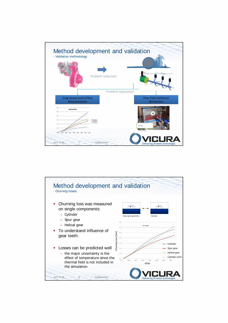
Method development and validation- Internal shaft flow

INLET(constant oil height)

1

2

3

PreChamber

Delivering driveline technologies2011-11-09 12 Torbjörn Kvist

Applications- Minimization of losses

Delivering driveline technologies2011-11-09 13 Torbjörn Kvist

40 deg C0 deg C

Temperature effect on flow field

Applications- Thermal effects

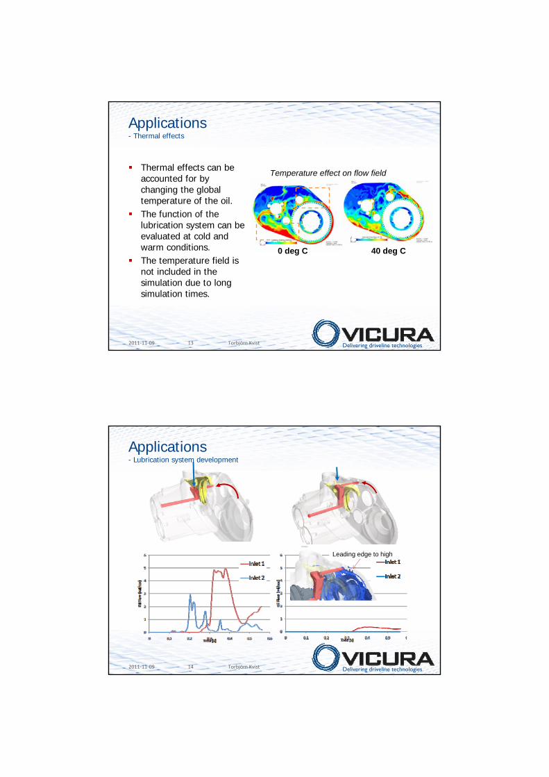
Thermal effects can be accounted for by changing the global temperature of the oil.The function of the lubrication system can be evaluated at cold and warm conditions.The temperature field is not included in the simulation due to long simulation times.

Delivering driveline technologies2011-11-09 14 Torbjörn Kvist

Leading edge to high

Applications- Lubrication system development

Delivering driveline technologies2011-11-09 15 Torbjörn Kvist

Applications- Transmission housing design

Lubrication

Manufacturing

Structure & NVH

Topology optimization

1st-time-rightHousing design!

Delivering driveline technologies2011-11-09 16 Torbjörn Kvist

SummaryA CFD method for splash lubrication has been developed and applied

Transient two-phase flow (oil and air)Rotating geometries

Complete transmissions can be simulated

The method is useful forMinimization of losses– Understanding geometrical effects– Minimize oil-level

Lubrication system– Understanding oil-flow to components under different driving conditions

(temperature, external forces, angle of inclination, …)– Design collector system and compare alternative solutions

Future improvements-Temperture field and heat transfer-Meshing gears-Additional component validation

-Bearings-Clutches-Synchronizers

-Simulation time

The method is used today for Vicura’scustomers

Delivering driveline technologies2011-11-09 17 Torbjörn Kvist

Thank you!

Movie

IS_OS_oil _guide_100.exe


Recommended