20
Surgical Manual Spline ® Implant System
Surgical Manual
Spline®
ImplantSystem
Spline Surgical Manual 4788.qxp 8/24/06 12:25 PM Page 2
Overview
Overview 1
Patient Evaluation & Selection
Patient Evaluation & Selection 1
Presurgical Planning
Presurgical Planning 1
Surgical Technique and Implant Placement
Autoclave Tray Drill Sequence 3
General Surgical Procedure 5
Sterilization Technique/Surgical Instrumentation 6
Bone Preparation 6
General Instructions for Implant Bed Preparation 7
Drill Extension Procedure 7
Surgical Drilling Guidelines 8
Surgical Autoclave Kit Drilling Sequence 10
Tapping The Surgical Site - 3.75mm & 5.0mm Spline Twist ™ Threaded Implants 10
Implant Placement for Spline Reliance™ Cylinder Implants 11
Implant Placement for Self Tapping Spline Twist Threaded Implants 12
Optional First Stage Impression for Spline Twist Threaded Implants Only 14
Single-Stage Procedure for Spline Twist Threaded Implants Only 14
Placement into Extraction Sockets 14
Exposure of Implants - Temporary Gingival Cuffs 15
Bone Contouring - Spline Dental Implant System Only 16
Yellow
Blue
Green
Black
3.25mm
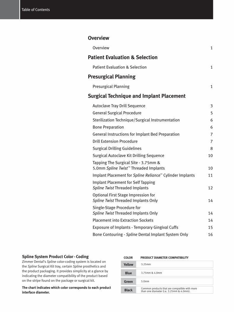
Spline System Product Color - CodingZimmer Dental’s Spline color-coding system is located on the Spline Surgical Kit tray, certain Spline prosthetics and the product packaging. It provides simplicity at a glance byindicating the diameter compatibility of the product based on the stripe found on the package or surgical kit.
The chart indicates which color corresponds to each productinterface diameter.
COLOR PRODUCT DIAMETER COMPATIBILITY
3.75mm & 4.0mm
5.0mm
Common products that are compatible with more than one diameter (i.e. 3.25mm & 4.0mm).
Table of Contents
Spline Surgical Manual 4788.qxp 8/24/06 12:25 PM Page 3
1Overview, Patient Evaluation & Selection and Presurgical Planning
The Surgical Products Manual (SPM) is designed to provide a basic overview of the presurgical and surgical proceduresapplicable to Spline Implant Systems.
Team ApproachSuccessful implant treatment requires the coordinated effortsof several dental professionals – the restorative dentist, the surgeon (periodontist, oral surgeon, general dentist), the laboratory technician, and the dental hygienist. By holding apresurgical conference, these individuals are able to developan appropriate treatment strategy. This provides a balancebetween esthetic, functional, and surgical goals. In addition, the coordinated approach ensures that treatment is complete,guarding against omission of important technical considerationssuch as the use of a surgical template for implant location.
Patient Evaluation & Selection• Take a general medical history
• Undertake a psycho-social evaluation
• Explore indications and contraindications
• Determine anatomical landmark considerations related toimplant positioning
• Determine feasible vertical dimensions
• Discuss treatment objectives and patient’s expectations
• Perform various radiographic evaluations
Presurgical PlanningProper stress distribution is essential to the long-term successof both the prosthesis and the implant. Overload is one of thekey contributors to implant failure and is especially importantin the cuspid and molar regions.
To minimize excessive loads, the following guidelines apply:
1. Reduce occlusal forces through reduction of the occlusaltable width.
2. Distribute occlusal forces optimally by maximizing the number of abutments used to support the prosthesisand placing implants of the maximum length and diameter allowable.
3. Position and incline the implants properly to ensure goodprosthetic design, function, and esthetics.
4. Cantilevering should not be part of a treatment plan due tothe force amplification of the resultant moment arm.
5. Strengthen the overall treatment plan in patients with either a heavy muscular profile or whose occlusal analysisindicates a strong bite by using the largest size implants,maximum numbers of abutments, minimizing the use ofcantilevers, and placing abutments for the most even distribution of occlusal loads.
Spline Dental Implants require a minimum of 4-6mm ofspace (rim-to-rim) depending on the restoration. A minimumof 3mm (not applicable to single tooth cases) is requiredbetween a natural tooth and the rim of an implant. A 1:1 implant-to-natural tooth root ratio should be followedwhen possible. Eight (8) millimeter implants should never be placed freestanding. The use of implants with a diameter ≥ 3.75mm is recommended in the posterior.
Spline Surgical Manual 4788.qxp 8/24/06 12:25 PM Page 4
2 Presurgical Planning
Implant Patient Maintenance• Review clinical hygiene procedures.
• Outline patient’s home-care hygiene regimen.
• Follow up on initial design, occlusion, and contouring forfunction, esthetic and hygienic evaluation.
• Examine patient on a routine recall basis.
Presurgical Planning (continued)
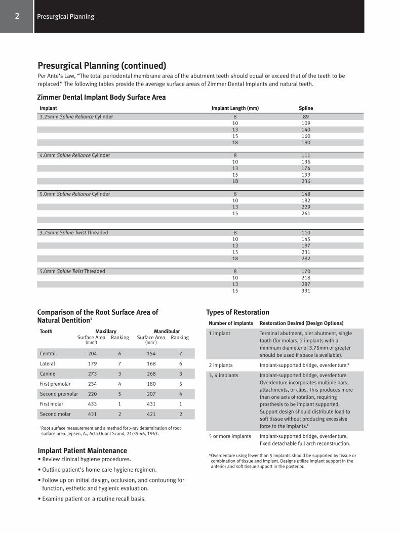
Implant Implant Length (mm) Spline
3.25mm Spline Reliance Cylinder 8 8910 10913 14015 16018 190
4.0mm Spline Reliance Cylinder 8 11110 13613 17415 19918 236
5.0mm Spline Reliance Cylinder 8 14810 18213 22915 261
3.75mm Spline Twist Threaded 8 11010 14513 19715 23118 282
5.0mm Spline Twist Threaded 8 17010 21813 28715 331
Zimmer Dental Implant Body Surface Area
Tooth Maxillary MandibularSurface Area Ranking Surface Area Ranking
(mm2) (mm2)
Central 204 6 154 7
Lateral 179 7 168 6
Canine 273 3 268 3
First premolar 234 4 180 5
Second premolar 220 5 207 4
First molar 433 1 431 1
Second molar 431 2 421 2
1Root surface measurement and a method for x-ray determination of rootsurface area. Jepsen, A., Acta Odont Scand, 21:35-46, 1963.
Comparison of the Root Surface Area ofNatural Dentition1
Number of Implants Restoration Desired (Design Options)
1 implant Terminal abutment, pier abutment, single tooth (for molars, 2 implants with a minimum diameter of 3.75mm or greater should be used if space is available).
2 implants Implant-supported bridge, overdenture.*
3, 4 implants Implant-supported bridge, overdenture. Overdenture incorporates multiple bars, attachments, or clips. This produces more than one axis of rotation, requiring prosthesis to be implant supported. Support design should distribute load to soft tissue without producing excessive force to the implants.*
5 or more implants Implant-supported bridge, overdenture, fixed detachable full arch reconstruction.
*Overdenture using fewer than 5 implants should be supported by tissue orcombination of tissue and implant. Designs utilize implant support in theanterior and soft tissue support in the posterior.
Types of Restoration
Per Ante’s Law, “The total periodontal membrane area of the abutment teeth should equal or exceed that of the teeth to bereplaced.” The following tables provide the average surface areas of Zimmer Dental Implants and natural teeth.
Spline Surgical Manual 4788.qxp 8/24/06 12:25 PM Page 5
3Surgical Technique and Implant Placement
Autoclave Tray Drill Sequence
3.25mm Spline Reliance Cylinder Implant1. Round Bur
2. 2.3mm Pilot Drill
3. Parallel Pin(s)
4. 3.0mm Intermediate Drill
5. Parallel Pin(s)
6. 3.25mm Countersink Drill
7. 3.25mm Final Drill
8. 3.25mm Implant Body Try-in
3.75mm Spline Twist Threaded Implant1. Round Bur
2. 2.3mm Pilot Drill
3. Parallel Pin(s)
4. 3.0mm Intermediate Drill
5. Parallel Pin(s)
6. 3.25mm Final Drill
7. 3.25mm Implant Body Try-in
8. 4.0mm Countersink Drill
9. 3.75mm Tap (optional)**
4.0mm Spline Reliance Cylinder Implant1. Round Bur
2. 2.3mm Pilot Drill
3. Parallel Pin(s)
4. 3.0mm Intermediate Drill
5. Parallel Pin(s)
6. 4.0mm Countersink Drill
7. 4.0mm Final Drill
8. 4.0mm Implant Body Try-in
5.0mm Spline Reliance Cylinder Implant1. Round Bur
2. 2.3mm Pilot Drill
3. Parallel Pin(s)
4. 3.0mm Intermediate Drill
5. Parallel Pin(s)
6. 4.0mm Final Drill
7. 4.5mm Intermediate Drill
8. 4.5mm Implant Body Try-in
9. 5.0mm Countersink Drill
10. 5.0mm Final Drill
5.0mm Spline Twist Threaded Implant1. Round Bur
2. 2.3mm Pilot Drill
3. Parallel Pin(s)
4. 3.0mm Intermediate Drill
5. Parallel Pin(s)
6. 4.0mm Final Drill
10. 4.5mm Intermediate Drill
11. 4.5mm Implant Body Try-in
12. 5.0mm Countersink Drill
13. 5.0mm Tap (optional)**
**Use of a Thread Tap for self-tappingimplants is not normally necessary.However, in dense bone (e.g. Type 1) pre-tapping the site may be necessary.Thread Taps should be available ifneeded.
Spline Surgical Manual 4788.qxp 8/24/06 12:25 PM Page 6
4 Surgical Technique and Implant Placement
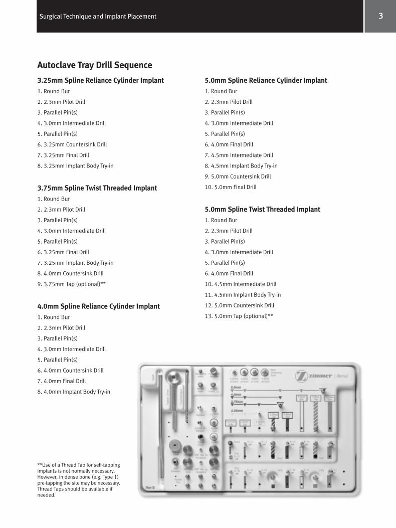
Autoclave Tray Drill Sequence (continued)Surgical Kit comes with all the instrumentation needed to place 3.25mm and 4.0mm Spline Reliance cylinder implants, Part Number 2410A.
3.25mm and 4.0mm Spline Reliance Cylinder and Spline Twist Threaded Surgical Kit, P/N 2410A Contents: Surgical Box and Tray
Round Bur
Pilot Drill, 8-13mm
Pilot Drill, 8-18mm
3.0mm Intermediate Drill, 8-13mm
3.0mm Intermediate Drill, 8-18mm
3.25mm Countersink Drill
3.25mm Final Drill, 8-13mm
3.25mm Final Drill, 8-18mm
4.0mm Countersink Drill
4.0mm Final Drill, 8-13mm
4.0mm Final Drill, 8-18mm
Drill Extension
Parallel Pins, Straight (Qty 4)
Parallel Pins, 15° (Qty 2)
Try-in, 3.25mm
Try-in, 4.0mm
Tapper Handle
3.25 Tapper Tips (Qty 4)
4.0 Tapper Tips (Qty 2)
Implant Body Retriever
Tissue Punch
Hex Driver, .035", Long (0.9mmD)
Hex Driver, .035", Short (0.9mmD)
Hex Driver, .050", Long (1.25mmD)
Hex Driver, .050", Short (1.25mmD)
3.25mm x 4.5mm Bone Contouring Tool
4.0mm x 4.5mm Bone Contouring Tool
Bone Contouring Tool Manual Driver
5.0mm Spline Reliance Cylinder and Spline TwistThreaded Surgical Kit, P/N 2412A Contents:5.0mm Countersink Drill
4.5mm Intermediate Drill, 8-13mm
4.5mm Intermediate Drill, 8-15mm
5.0mm Final Drill, 8-18mm
5.0mm Final Drill, 8-15mm
4.5mm Implant Body Try-in
5.0mm x 6.5mm Bone Contouring Tool
*Surgical tray and threaded delivery tools not included
5.0mm Spline Twist Threaded Surgical Kit, P/N 2414A Contents:5.0mm Countersink Drill
4.5mm Intermediate Drill, 8-13mm
4.5mm Intermediate Drill, 8-15mm
4.5mm Implant Body Try-in
5.0mm x 6.5mm Bone Contouring Tool
*Surgical tray and threaded delivery tools not included
Sterilization Guidelines:Please remove any protective packaging from the surgical traybefore sterilization. The following are suggested guidelines forsterilization. Use commercially available chemical or biologicalmonitors to determine the efficacy of the cycle employed.
• Steam Autoclave at 121°C/250°F, 15-20 psig for 40 minutesminimum followed by a 30 minute dry cycle.
• Dry heat at 160°C/320°F, for 2 hours (do not exceed170°C/338°F).
• Chemclaving and flashclaving is NOT recommended.
Note: Exceeding these sterilization parameters may result in damage to plastic components. Verify the calibration of your unit to ensure recommendedtemperatures are not being exceeded.
Spline Surgical Manual 4788.qxp 8/24/06 12:25 PM Page 7
5Surgical Technique and Implant Placement
It is important that the implant procedure be performed underaseptic conditions. Irrigation technique should be reviewed toensure that compressed coolant air is not introduced into thesurgical site via a drill. All instruments must be clean and sterile. Please note that the surgical instrumentation used toplace dental implants is provided non-sterile and thereforemust be sterilized prior to use. The sterilization chart on page 6 provides specific sterilization instructions.
HandlingOnly powder-free gloved hands or non-metallic instrumentsshould be used to handle the implant. Implants are packagedto protect the product from damage during transit and storage.
CleaningUse the following guidelines for cleaning components:
Surgical Drills - Rinse with cool to lukewarm water for two-and-one-half minutes. Use a 25-gauge or 30-gauge* needle to clean the lumen, making sure to flush water throughthe needle. Place in an ultrasonic cleaner with an enzymaticdetergent mixed with tap water per the manufacturer’sguidelines. Sonicate for 10 minutes. Rinse with tap water for three minutes.
Prosthetic Components - Disassemble two piece components.Rinse in cool to lukewarm water for two-and-one-half minutes.Place in an ultrasonic cleaner with an enzymatic detergentmixed with tap water per the manufacturer’s guidelines.Sonicate for 10 minutes.
Surgical and Prosthetic Tools - Rinse with cool to lukewarmwater for two-and-one-half minutes. Wipe with cotton gauzemoistened with tap water. Use multipurpose soft bristle brushto remove excess soil. Wipe with a two percent glutaraldehydesolution. Let tool sit for five minutes. Rinse with tap water forthree minutes (see page 6).
Surgical Tray and Second Stage/Prosthetic Tray - Remove allparts from the surgical tray, then remove the tray insert. Rinse the tray and tray insert thoroughly with cool to lukewarm(43°C/110°F or less) tap water. Use a damp cloth to wipe andremove any excess soil from each part. After rinsing, wipeeach part with a cloth that has been dipped in an enzymaticdetergent solution diluted to manufacturer’s specifications.Wipe parts until all visible contamination has been removed.To eliminate all residual enzymes and detergent, thoroughlyrinse (minimum of three minutes) the cleaned parts with tapwater. Note: This procedure should be performed after aninstrument used during a surgery comes into contact with thesurgical tray or second stage/prosthetic tray.
SterilizationSterile products have been gamma radiation sterilized and are for single use only. Only HA-Coated implant bodies maybe resterilized. Resterilize once (HA-Coated implants can be sterilized by autoclaving or dry heat) if the sterile packaginghas been opened, but only if the implant has not been contaminated in any manner. If resterilization is needed,remove the cap, healing screw, and any implant driver mounts from the body. Place the healing screw, implant, and any implant driver mount in an appropriate container forsterilization. Do not sterilize the implant body with the healingscrew in place. Do not sterilize the cap or vial. Repeated autoclaving is not advised.
Zimmer Dental Spline surgical instrumentation and prostheticcomponents are provided non-sterile and must be sterilizedprior to use. Remove instrumentation or prosthetic componentsfrom packaging prior to sterilization. Refer to the following tablefor instrumentation sterilization guidelines. Note: Two-piececomponents should be disassembled prior to sterilization toensure maximum efficacy.
*All drills 2.8mmD or smaller will require a 30-gauge needle to clean the lumen.
General Surgical Procedure
Spline Surgical Manual 4788.qxp 8/24/06 12:25 PM Page 8
6 Surgical Technique and Implant Placement
Product Autoclave1 Dry Heat
HA-Coated Implants yes2 (only once) yes2 (only once)
Pilot Drill yes yes4
Round Bur yes yes
Intermediate Drills yes yes4
Countersink Drills yes yes4
Final Drills yes yes4
Spline Bone Contouring Tools yes yes
Manual Driver - Spline Bone yes noContouring Tools
Drill Extension yes yes
Thread Taps yes no
Implant/Tap Driver yes no
Handpiece Adapter yes yes
Manual Mount Driver yes yes
Latch-Lock Mount Driver yes yes
Countertorque Tool yes yes
Healing Screws yes yes
Parallel Pins yes yes
Implant Body Try-ins yes yes
Prosthetic Torque Wrench yes no
Hex Drive Seating Tool yes yes
Tapper/Tapper Tips yes yes4
Implant Body Retriever yes yes
Tissue Punch yes no
Temporary Gingival Cuffs yes yes
Autoclave Tray (Cat. No. 2309) yes yes4
Suggested Parameters 121°C/250°F 160°C/320°F(guidelines only)3 15-20 psig 2 hrs
40 minutes minimum followed by a
30 minute dry cycle
Sterilization Technique/Surgical Instrumentation
1 A standard autoclave bag should be used. Check trays, autoclave interior, andwater supply for cleanliness. The autoclave should have a drying cycle.
2 Implant body must not be contaminated.3 Use commercially available chemical or biological monitors to determine the
efficacy of the actual cycle employed.4 Due to the melting point of the plastics used in these products, dry heat
sterilization should not exceed 170°C/338°F.
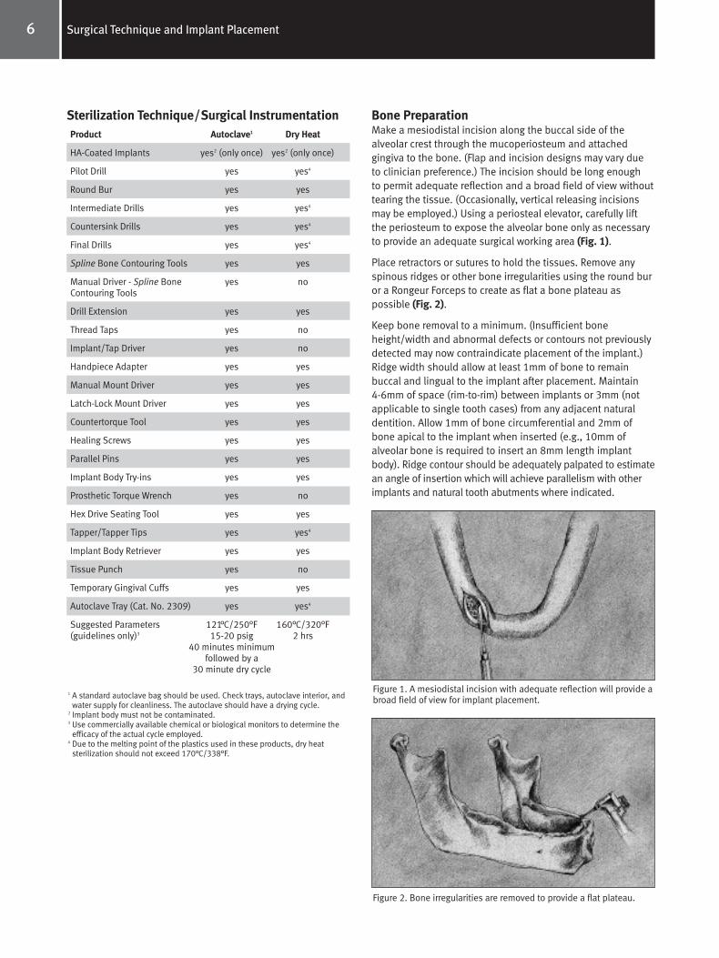
Bone PreparationMake a mesiodistal incision along the buccal side of the alveolar crest through the mucoperiosteum and attached gingiva to the bone. (Flap and incision designs may vary dueto clinician preference.) The incision should be long enough to permit adequate reflection and a broad field of view withouttearing the tissue. (Occasionally, vertical releasing incisionsmay be employed.) Using a periosteal elevator, carefully liftthe periosteum to expose the alveolar bone only as necessaryto provide an adequate surgical working area (Fig. 1).
Place retractors or sutures to hold the tissues. Remove anyspinous ridges or other bone irregularities using the round buror a Rongeur Forceps to create as flat a bone plateau aspossible (Fig. 2).
Keep bone removal to a minimum. (Insufficient boneheight/width and abnormal defects or contours not previouslydetected may now contraindicate placement of the implant.)Ridge width should allow at least 1mm of bone to remain buccal and lingual to the implant after placement. Maintain 4-6mm of space (rim-to-rim) between implants or 3mm (notapplicable to single tooth cases) from any adjacent naturaldentition. Allow 1mm of bone circumferential and 2mm ofbone apical to the implant when inserted (e.g., 10mm ofalveolar bone is required to insert an 8mm length implantbody). Ridge contour should be adequately palpated to estimatean angle of insertion which will achieve parallelism with otherimplants and natural tooth abutments where indicated.
Figure 1. A mesiodistal incision with adequate reflection will provide abroad field of view for implant placement.
Figure 2. Bone irregularities are removed to provide a flat plateau.
Spline Surgical Manual 4788.qxp 8/24/06 12:25 PM Page 9
7Surgical Technique and Implant Placement
General Instructions for Implant Bed PreparationBone cutting procedures involving the Pilot, 3.0mm Intermediate,and 3.25, 4.0, 4.5 and 5.0mm drills require a low speed (600-850rpm), high-torque, internally irrigated handpiece. This will minimizeexcessive heat generation and preserve the vitality of bone which isin contact with the implant. The Thread Taps do not accommodateinternal irrigation and external irrigation is required. If the ThreadTaps will be operated in a handpiece, a contra-angle that operatesat less than 50 rpm is required and the handpiece must be capableof high torque operation.
Irrigation techniques should be reviewed to ensure thatcompressed coolant air is not introduced into the surgical site via a surgical bur. Because profuse internal irrigation is required tokeep the drill from clogging, avoid splitting or diverting the drill’sinternal irrigation for external purposes. Accommodate externalirrigation by utilizing a sterile, water-filled syringe.
Perform all drilling, particularly with 2.3mmD Pilot, 3.0, 3.25, 4.0, 4.5 and 5.0mm drills, with a straight, up-and-down motion in order to avoid creation of an oval-shaped osteotomy site.
When additional drill length is required, a Drill Extension isavailable that extends the effective cutting length of the drill by10mm. The Drill Extension should be used when additional lengthis required due to interference caused by adjacent teeth. The DrillExtension has a standard latch-lock shank with a cylindrical shaftto lock any Zimmer Dental latch-lock type drill into the extensionwith a set screw. Do not use with drills other than the standardlatch-lock type. In addition, do not use excessive drilling speeds(i.e., speeds greater than 850 rpm) with the Drill Extension. The Drill Extension allows for internal irrigation. Note: The DrillExtension is not used with the Thread Taps or Driver Extension.
Drill Extension ProcedureA. Insert any Zimmer Dental latch-lock drill into the internal bore.
B. Rotate the drill until it seats positively inside of the bore.
C. Using the 1.25mmD (0.050") Hex Tool, tighten the set screw.Note: Tightening the set screw requires that the drill be positively engaged. Failure to engage may strip the set screw.
D. To remove the drill from the extension, loosen the set screw one-half to three-quarters of a turn and remove the drill. Note: The drill extension is provided with a positive mechanicalstop to prevent the set screw from being removed from the drillextension body. Do not use excessive force when loosening the screw.
Note: Clean drill heads often to remove debris and ensure a sharp cutting surface. A 25-gauge or 30-gauge needle can be used to clean the drill’s irrigation hole. Due to the density of bone commonly found in the symphysis region, use newer drills. Rotate these drills for use in the maxilla or where more porousbone is found (Type II or III). A maximum of 20 uses per drill isrecommended.
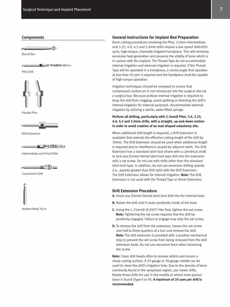
Round Bur
Pilot Drill
Parallel Pins
Intermediate and Final Drills
Drill Extension
Countersink Drill
Implant Body Try-in
Components
Spline Surgical Manual 4788.qxp 8/24/06 12:25 PM Page 10
8 Surgical Technique and Implant Placement
Surgical Drilling GuidelinesPlease refer to the additional surgical drilling guidelinesbelow before following the surgical charts. These guidelinescorrespond and provide additional information to the surgicalsequencing found in the charts.
Explanation of Depth BandsThe bands on the Pilot, 3.0mm, 3.25mm, 4.0mm, 4.5mm, and5.0mm diameter drills are cutting depth markings indicatingimplant length. The depth markings are machined and laseretched for increased visibility. Also note the addition of adepth band to indicate the placement of the 11.5mm SplineTwist Implant. The bands are located 1mm longer than theimplant abutment junction. (For example: The 13mm band isdimensioned 14mm from the tip of the drill.) This lengthshould be chosen on a case by case basis taking into accountbone irregularities at the crest. Always take into account vitalanatomical structures when allowing for additional length during surgical site excavation.A. Use copious external irrigation with the Round (Rosette) Bur
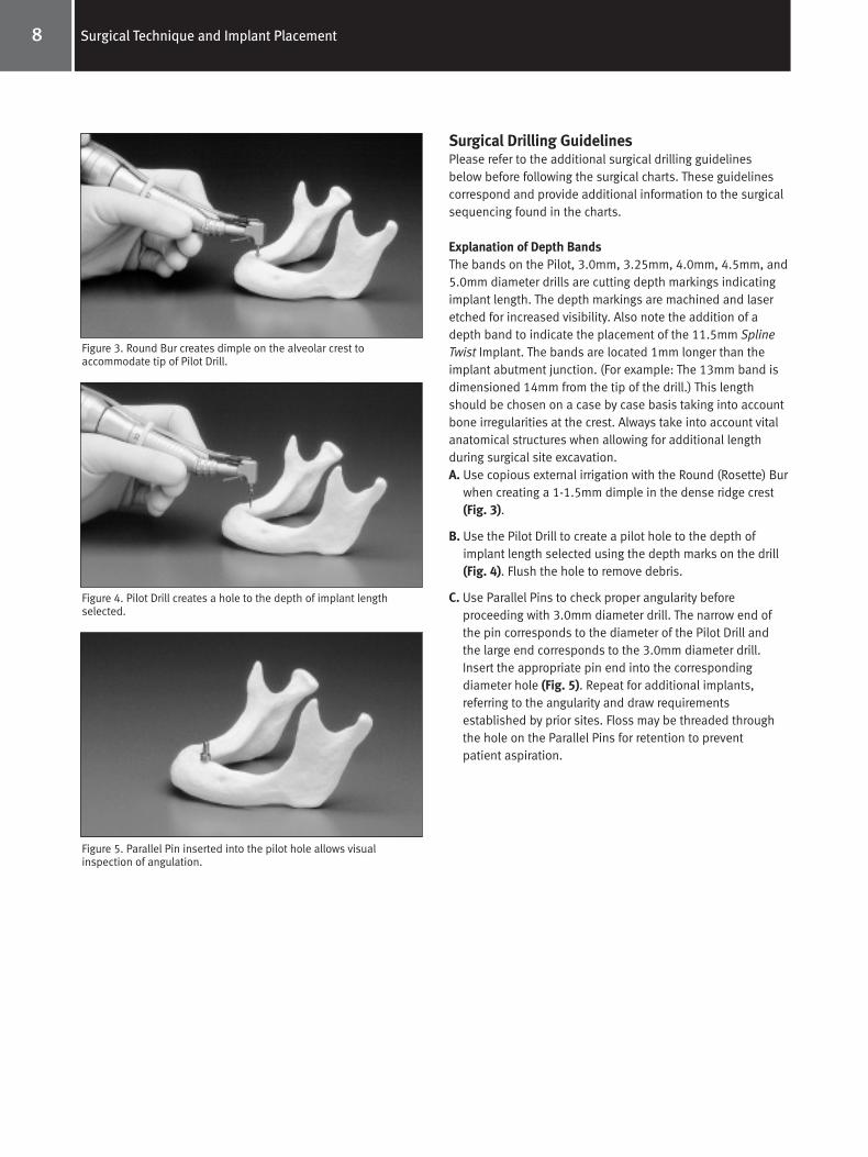
when creating a 1-1.5mm dimple in the dense ridge crest(Fig. 3).
B. Use the Pilot Drill to create a pilot hole to the depth ofimplant length selected using the depth marks on the drill(Fig. 4). Flush the hole to remove debris.
C. Use Parallel Pins to check proper angularity before proceeding with 3.0mm diameter drill. The narrow end ofthe pin corresponds to the diameter of the Pilot Drill andthe large end corresponds to the 3.0mm diameter drill.Insert the appropriate pin end into the corresponding diameter hole (Fig. 5). Repeat for additional implants, referring to the angularity and draw requirementsestablished by prior sites. Floss may be threaded throughthe hole on the Parallel Pins for retention to preventpatient aspiration.
Figure 3. Round Bur creates dimple on the alveolar crest to accommodate tip of Pilot Drill.
Figure 4. Pilot Drill creates a hole to the depth of implant lengthselected.
Figure 5. Parallel Pin inserted into the pilot hole allows visualinspection of angulation.
Spline Surgical Manual 4788.qxp 8/24/06 12:25 PM Page 11
9Surgical Technique and Implant Placement
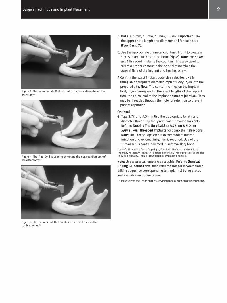
D. Drills 3.25mm, 4.0mm, 4.5mm, 5.0mm. Important: Use the appropriate length and diameter drill for each step(Figs. 6 and 7).
E. Use the appropriate diameter countersink drill to create arecessed area in the cortical bone (Fig. 8). Note: For SplineTwist Threaded Implants the countersink is also used to create a proper contour in the bone that matches the coronal flare of the implant and healing screw.
F. Confirm the exact implant body size selection by trialfitting an appropriate diameter Implant Body Try-in into the prepared site. Note: The concentric rings on the ImplantBody Try-in correspond to the exact lengths of the implantfrom the apical end to the implant-abutment junction. Flossmay be threaded through the hole for retention to preventpatient aspiration.
Optional:G. Taps 3.75 and 5.0mm: Use the appropriate length and
diameter Thread Tap for Spline Twist Threaded Implants.Refer to Tapping The Surgical Site 3.75mm & 5.0mm Spline Twist Threaded Implants for complete instructions.Note: The Thread Taps do not accommodate internalirrigation and external irrigation is required. Use of theThread Tap is contraindicated in soft maxillary bone.
*Use of a Thread Tap for self-tapping Spline Twist Threaded Implants is notnormally necessary. However, in dense bone (e.g., Type I) pre-tapping the sitemay be necessary. Thread Taps should be available if needed.
Note: Use a surgical template as a guide. Refer to SurgicalDrilling Guidelines first, then refer to table for recommendeddrilling sequence corresponding to implant(s) being placedand available instrumentation.
**Please refer to the charts on the following pages for surgical drill sequencing.
Figure 8. The Countersink Drill creates a recessed area in the cortical bone.**
Figure 6. The Intermediate Drill is used to increase diameter of theosteotomy.
Figure 7. The Final Drill is used to complete the desired diameter ofthe osteotomy.*
Spline Surgical Manual 4788.qxp 8/24/06 12:25 PM Page 12
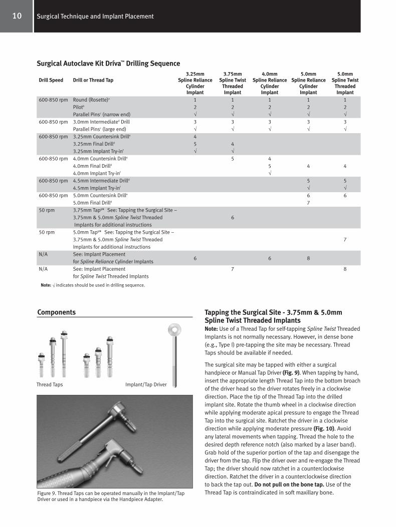
Tapping the Surgical Site - 3.75mm & 5.0mmSpline Twist Threaded ImplantsNote: Use of a Thread Tap for self-tapping Spline Twist ThreadedImplants is not normally necessary. However, in dense bone(e.g., Type I) pre-tapping the site may be necessary. ThreadTaps should be available if needed.
The surgical site may be tapped with either a surgicalhandpiece or Manual Tap Driver (Fig. 9). When tapping by hand,insert the appropriate length Thread Tap into the bottom broachof the driver head so the driver rotates freely in a clockwisedirection. Place the tip of the Thread Tap into the drilledimplant site. Rotate the thumb wheel in a clockwise directionwhile applying moderate apical pressure to engage the ThreadTap into the surgical site. Ratchet the driver in a clockwisedirection while applying moderate pressure (Fig. 10). Avoidany lateral movements when tapping. Thread the hole to thedesired depth reference notch (also marked by a laser band).Grab hold of the superior portion of the tap and disengage thedriver from the tap. Flip the driver over and re-engage the ThreadTap; the driver should now ratchet in a counterclockwise direction. Ratchet the driver in a counterclockwise direction to back the tap out. Do not pull on the bone tap. Use of theThread Tap is contraindicated in soft maxillary bone.
10 Surgical Technique and Implant Placement
Drill Speed
600-850 rpm
600-850 rpm
600-850 rpm
600-850 rpm
600-850 rpm
600-850 rpm
50 rpm
50 rpm
N/A
N/A
Surgical Autoclave Kit Dríva™ Drilling Sequence
Thread Taps Implant/Tap Driver
Figure 9. Thread Taps can be operated manually in the Implant/TapDriver or used in a handpiece via the Handpiece Adapter.
Components
Note: √ indicates should be used in drilling sequence.
3.25mm 3.75mm 4.0mm 5.0mm 5.0mmDrill or Thread Tap Spline Reliance Spline Twist Spline Reliance Spline Reliance Spline Twist
Cylinder Threaded Cylinder Cylinder Threaded Implant Implant Implant Implant Implant
Round (Rosette)a 1 1 1 1 1Pilotb 2 2 2 2 2Parallel Pinsc (narrow end) √ √ √ √ √3.0mm Intermediated Drill 3 3 3 3 3Parallel Pinsc (large end) √ √ √ √ √3.25mm Countersink Drille 43.25mm Final Drilld 5 43.25mm Implant Try-inf √ √4.0mm Countersink Drille 5 44.0mm Final Drilld 5 4 44.0mm Implant Try-inf √4.5mm Intermediate Drilld 5 54.5mm Implant Try-inf √ √5.0mm Countersink Drille 6 65.0mm Final Drilld 73.75mm Tapg* See: Tapping the Surgical Site – 3.75mm & 5.0mm Spline Twist Threaded 6Implants for additional instructions
5.0mm Tapg* See: Tapping the Surgical Site – 3.75mm & 5.0mm Spline Twist Threaded 7Implants for additional instructionsSee: Implant Placement
6 6 8for Spline Reliance Cylinder ImplantsSee: Implant Placement 7 8for Spline Twist Threaded Implants
Spline Surgical Manual 4788.qxp 8/24/06 12:25 PM Page 13

11Surgical Technique and Implant Placement
Figure 10. Thread Tap is ratcheted clockwise to the appropriate depthreference notch.
When using the handpiece, place the appropriate lengthThread Tap in the Handpiece Adapter. The Handpiece Adapterwill fit any latch-lock handpiece. Place the tip of the Thread Tap into the drilled implant site. The rotational speed for thetapping procedure should be below 50 rpm. This may require a change in contra-angle, capable of low speed, high torqueoperation. Apply firm pressure and begin rotating the ThreadTap slowly. When the threads engage, allow the Thread Tap tofeed without pressure. Thread the hole to the desired depthreference notch (also marked by a laser band). Switch thehandpiece to the reverse mode and back the Thread Tap out.Do not pull on the Thread Tap. Use of the Thread Tap iscontraindicated in soft maxillary bone. After site has beentapped reference: Implant Placement For Spline TwistThreaded Implants.
Implant Placement for Cylinder ImplantsA. Irrigate the completed implant receptor site with additional
sterile water.
B. While holding the plastic cap, seat the implant into the prepared site (Fig. 11) until firm (at least halfway).
C. Remove the plastic cap by applying a steady pressure to thecap perpendicular to long axis of implant in a mesial or distaldirection. The cap will “snap” off. Fully seat the implant (thetop of healing screw flush or slightly above crest of alveolarbone) using a gentle tapping action with a rubber mallet onthe plastic-tipped Tapper (Fig. 12). Check the healing screwfor tightness with the hex drive seating tool.
D. A radiographic check of implant placement should be performed at this time.
E. Carefully reposition the mucoperiosteal flap for maximumtissue adaptation, and then suture.
3.25 MP-1®
Spline Reliance Cylinder Implants
4.0 MP-1 5.0 MP-1
Figure 11. The cylindrical implant is initially delivered to the site viathe vial cap.
Figure 12. The Tapper may be used to facilitate final seating ofcylindrical implants.
Components
Spline Surgical Manual 4788.qxp 8/24/06 12:25 PM Page 14
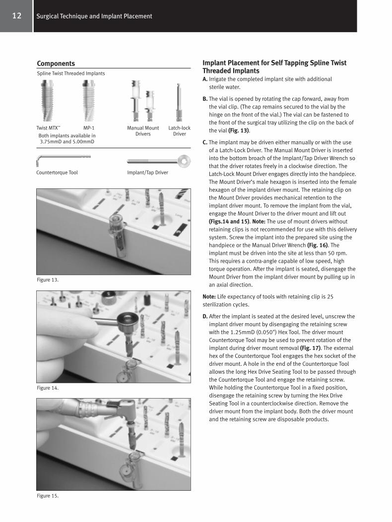
Implant Placement for Self Tapping Spline TwistThreaded ImplantsA. Irrigate the completed implant site with additional
sterile water.
B. The vial is opened by rotating the cap forward, away fromthe vial clip. (The cap remains secured to the vial by thehinge on the front of the vial.) The vial can be fastened tothe front of the surgical tray utilizing the clip on the back ofthe vial (Fig. 13).
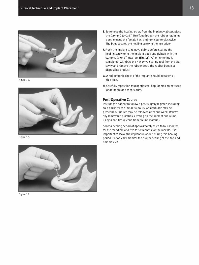
C. The implant may be driven either manually or with the useof a Latch-Lock Driver. The Manual Mount Driver is insertedinto the bottom broach of the Implant/Tap Driver Wrench sothat the driver rotates freely in a clockwise direction. TheLatch-Lock Mount Driver engages directly into the handpiece.The Mount Driver’s male hexagon is inserted into the femalehexagon of the implant driver mount. The retaining clip onthe Mount Driver provides mechanical retention to theimplant driver mount. To remove the implant from the vial,engage the Mount Driver to the driver mount and lift out(Figs.14 and 15). Note: The use of mount drivers withoutretaining clips is not recommended for use with this deliverysystem. Screw the implant into the prepared site using thehandpiece or the Manual Driver Wrench (Fig. 16). Theimplant must be driven into the site at less than 50 rpm.This requires a contra-angle capable of low speed, hightorque operation. After the implant is seated, disengage theMount Driver from the implant driver mount by pulling up inan axial direction.
Note: Life expectancy of tools with retaining clip is 25 sterilization cycles.
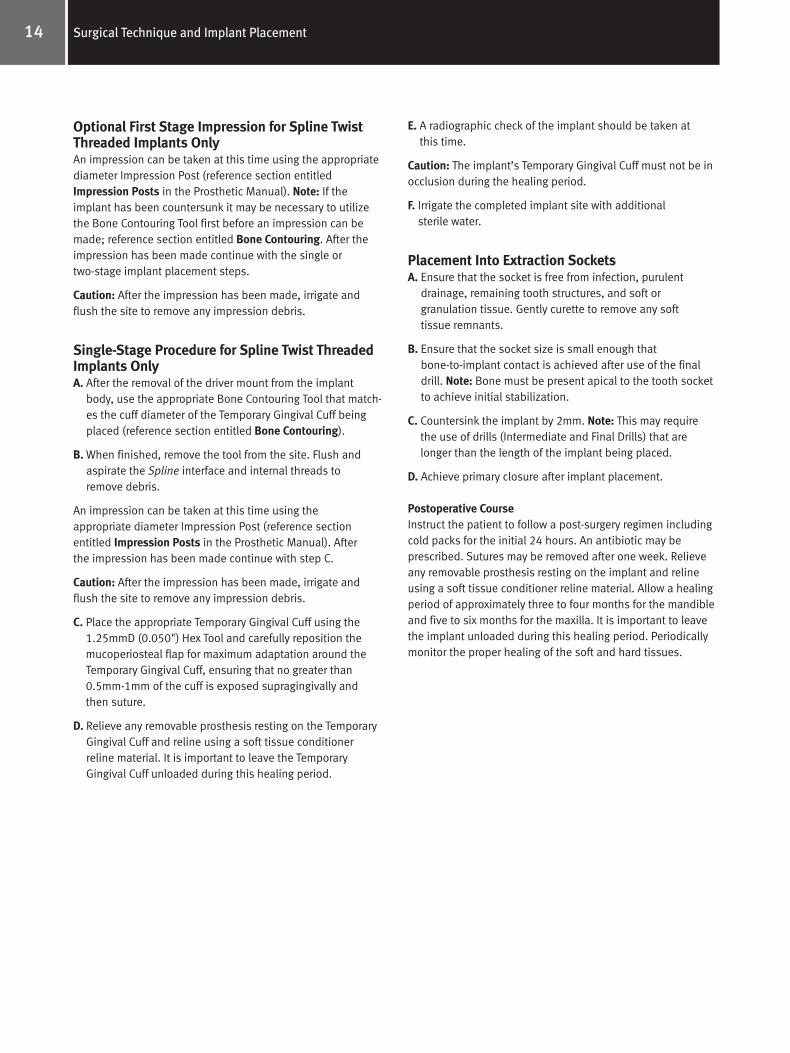
D. After the implant is seated at the desired level, unscrew theimplant driver mount by disengaging the retaining screwwith the 1.25mmD (0.050") Hex Tool. The driver mountCountertorque Tool may be used to prevent rotation of theimplant during driver mount removal (Fig. 17). The externalhex of the Countertorque Tool engages the hex socket of thedriver mount. A hole in the end of the Countertorque Toolallows the long Hex Drive Seating Tool to be passed throughthe Countertorque Tool and engage the retaining screw.While holding the Countertorque Tool in a fixed position, disengage the retaining screw by turning the Hex Drive Seating Tool in a counterclockwise direction. Remove thedriver mount from the implant body. Both the driver mountand the retaining screw are disposable products.
12 Surgical Technique and Implant Placement
Figure 13.
Figure 14.
Figure 15.
Twist MTX™ MP-1 Manual MountDrivers
Latch-lockDriverBoth implants available in
3.75mmD and 5.00mmD
Spline Twist Threaded Implants
Countertorque Tool Implant/Tap Driver
Components
Spline Surgical Manual 4788.qxp 8/24/06 12:25 PM Page 15
13Surgical Technique and Implant Placement
E. To remove the healing screw from the implant vial cap, placethe 0.9mmD (0.035") Hex Tool through the rubber retainingboot, engage the female hex, and turn counterclockwise.The boot secures the healing screw to the hex driver.
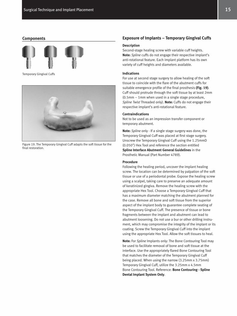
F. Flush the implant to remove debris before seating the healing screw onto the implant body and tighten with the0.9mmD (0.035") Hex Tool (Fig. 18). After tightening iscompleted, withdraw the Hex Drive Seating Tool from the oralcavity and remove the rubber boot. The rubber boot is a disposable product.
G. A radiographic check of the implant should be taken atthis time.
H. Carefully reposition mucoperiosteal flap for maximum tissueadaptation, and then suture.
Post-Operative CourseInstruct the patient to follow a post-surgery regimen includingcold packs for the initial 24 hours. An antibiotic may be prescribed. Sutures may be removed after one week. Relieveany removable prosthesis resting on the implant and relineusing a soft tissue conditioner reline material.
Allow a healing period of approximately three to four monthsfor the mandible and five to six months for the maxilla. It isimportant to leave the implant unloaded during this healingperiod. Periodically monitor the proper healing of the soft andhard tissues.
Figure 16.
Figure 17.
Figure 18.
Spline Surgical Manual 4788.qxp 8/24/06 12:25 PM Page 16
Optional First Stage Impression for Spline TwistThreaded Implants OnlyAn impression can be taken at this time using the appropriatediameter Impression Post (reference section entitledImpression Posts in the Prosthetic Manual). Note: If theimplant has been countersunk it may be necessary to utilizethe Bone Contouring Tool first before an impression can bemade; reference section entitled Bone Contouring. After theimpression has been made continue with the single or two-stage implant placement steps.
Caution: After the impression has been made, irrigate andflush the site to remove any impression debris.
Single-Stage Procedure for Spline Twist ThreadedImplants OnlyA. After the removal of the driver mount from the implant
body, use the appropriate Bone Contouring Tool that match-es the cuff diameter of the Temporary Gingival Cuff beingplaced (reference section entitled Bone Contouring).
B. When finished, remove the tool from the site. Flush andaspirate the Spline interface and internal threads to remove debris.
An impression can be taken at this time using the appropriate diameter Impression Post (reference section entitled Impression Posts in the Prosthetic Manual). After the impression has been made continue with step C.
Caution: After the impression has been made, irrigate andflush the site to remove any impression debris.
C. Place the appropriate Temporary Gingival Cuff using the1.25mmD (0.050") Hex Tool and carefully reposition themucoperiosteal flap for maximum adaptation around theTemporary Gingival Cuff, ensuring that no greater than0.5mm-1mm of the cuff is exposed supragingivally and then suture.
D. Relieve any removable prosthesis resting on the TemporaryGingival Cuff and reline using a soft tissue conditionerreline material. It is important to leave the TemporaryGingival Cuff unloaded during this healing period.
E. A radiographic check of the implant should be taken atthis time.
Caution: The implant’s Temporary Gingival Cuff must not be inocclusion during the healing period.
F. Irrigate the completed implant site with additionalsterile water.
Placement Into Extraction SocketsA. Ensure that the socket is free from infection, purulent
drainage, remaining tooth structures, and soft or granulation tissue. Gently curette to remove any softtissue remnants.
B. Ensure that the socket size is small enough thatbone-to-implant contact is achieved after use of the finaldrill. Note: Bone must be present apical to the tooth socketto achieve initial stabilization.
C. Countersink the implant by 2mm. Note: This may require the use of drills (Intermediate and Final Drills) that arelonger than the length of the implant being placed.
D. Achieve primary closure after implant placement.
Postoperative CourseInstruct the patient to follow a post-surgery regimen includingcold packs for the initial 24 hours. An antibiotic may be prescribed. Sutures may be removed after one week. Relieveany removable prosthesis resting on the implant and relineusing a soft tissue conditioner reline material. Allow a healingperiod of approximately three to four months for the mandibleand five to six months for the maxilla. It is important to leavethe implant unloaded during this healing period. Periodicallymonitor the proper healing of the soft and hard tissues.
14 Surgical Technique and Implant Placement
Spline Surgical Manual 4788.qxp 8/24/06 12:25 PM Page 17
15Surgical Technique and Implant Placement
Exposure of Implants – Temporary Gingival Cuffs
DescriptionSecond-stage healing screw with variable cuff heights. Note: Spline cuffs do not engage their respective implant’santi-rotational feature. Each implant platform has its own variety of cuff heights and diameters available.
IndicationsFor use at second stage surgery to allow healing of the softtissue to coincide with the flare of the abutment cuffs for suitable emergence profile of the final prosthesis (Fig. 19).Cuff should protrude through the soft tissue by at least 2mm(0.5mm – 1mm when used in a single stage procedure, Spline Twist Threaded only). Note: Cuffs do not engage theirrespective implant’s anti-rotational feature.
ContraindicationsNot to be used as an impression transfer component or temporary abutment.
Note: Spline only - If a single stage surgery was done, theTemporary Gingival Cuff was placed at first stage surgery.Unscrew the Temporary Gingival Cuff using the 1.25mmD(0.050") Hex Tool and reference the section entitled Spline Interface Abutment General Guidelines in theProsthetic Manual (Part Number 4789).
ProcedureFollowing the healing period, uncover the implant healingscrew. The location can be determined by palpation of the softtissue or use of a periodontal probe. Expose the healing screwusing a scalpel, taking care to preserve an adequate amountof keratinized gingiva. Remove the healing screw with theappropriate Hex Tool. Choose a Temporary Gingival Cuff thathas a maximum diameter matching the abutment planned forthe case. Remove all bone and soft tissue from the superioraspect of the implant body to guarantee complete seating ofthe Temporary Gingival Cuff. The presence of tissue or bonefragments between the implant and abutment can lead toabutment loosening. Do not use a bur or other drilling instru-ment, which may compromise the integrity of the implant or itscoating. Screw the Temporary Gingival Cuff into the implantusing the appropriate Hex Tool. Allow the soft tissues to heal.
Note: For Spline Implants only: The Bone Contouring Tool maybe used to facilitate removal of bone and soft tissue at theinterface. Use the appropriately flared Bone Contouring Toolthat matches the diameter of the Temporary Gingival Cuffbeing placed. When using the narrow (3.25mm x 3.75mm)Temporary Gingival Cuff, utilize the 3.25mm x 4.5mm Bone Contouring Tool. Reference: Bone Contouring - Spline Dental Implant System Only.
Components
Temporary Gingival Cuffs
Figure 19. The Temporary Gingival Cuff adapts the soft tissue for thefinal restoration.
Spline Surgical Manual 4788.qxp 8/24/06 12:25 PM Page 18
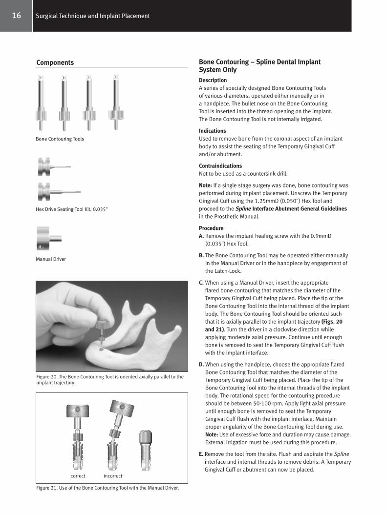
Bone Contouring – Spline Dental ImplantSystem OnlyDescriptionA series of specially designed Bone Contouring Toolsof various diameters, operated either manually or in a handpiece. The bullet nose on the Bone Contouring Tool is inserted into the thread opening on the implant. The Bone Contouring Tool is not internally irrigated.
IndicationsUsed to remove bone from the coronal aspect of an implantbody to assist the seating of the Temporary Gingival Cuffand/or abutment.
ContraindicationsNot to be used as a countersink drill.
Note: If a single stage surgery was done, bone contouring wasperformed during implant placement. Unscrew the TemporaryGingival Cuff using the 1.25mmD (0.050") Hex Tool and proceed to the Spline Interface Abutment General Guidelinesin the Prosthetic Manual.
ProcedureA. Remove the implant healing screw with the 0.9mmD
(0.035") Hex Tool.
B. The Bone Contouring Tool may be operated either manuallyin the Manual Driver or in the handpiece by engagement ofthe Latch-Lock.
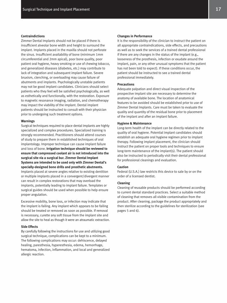
C. When using a Manual Driver, insert the appropriate flared bone contouring that matches the diameter of theTemporary Gingival Cuff being placed. Place the tip of theBone Contouring Tool into the internal thread of the implantbody. The Bone Contouring Tool should be oriented suchthat it is axially parallel to the implant trajectory (Figs. 20and 21). Turn the driver in a clockwise direction while applying moderate axial pressure. Continue until enoughbone is removed to seat the Temporary Gingival Cuff flushwith the implant interface.
D. When using the handpiece, choose the appropriate flaredBone Contouring Tool that matches the diameter of theTemporary Gingival Cuff being placed. Place the tip of theBone Contouring Tool into the internal threads of the implantbody. The rotational speed for the contouring procedureshould be between 50-100 rpm. Apply light axial pressureuntil enough bone is removed to seat the TemporaryGingival Cuff flush with the implant interface. Maintainproper angularity of the Bone Contouring Tool during use.Note: Use of excessive force and duration may cause damage.External irrigation must be used during this procedure.
E. Remove the tool from the site. Flush and aspirate the Splineinterface and internal threads to remove debris. A TemporaryGingival Cuff or abutment can now be placed.
16 Surgical Technique and Implant Placement
Components
Bone Contouring Tools
Hex Drive Seating Tool Kit, 0.035"
Manual Driver
Figure 20. The Bone Contouring Tool is oriented axially parallel to theimplant trajectory.
Figure 21. Use of the Bone Contouring Tool with the Manual Driver.
correct incorrect
Spline Surgical Manual 4788.qxp 8/24/06 12:25 PM Page 19
17Surgical Technique and Implant Placement
Changes in PerformanceIt is the responsibility of the clinician to instruct the patient onall appropriate contraindications, side effects, and precautionsas well as to seek the services of a trained dental professionalif there are any changes in the status of the implant (e.g.,looseness of the prosthesis, infection or exudate around theimplant, pain, or any other unusual symptoms that the patienthas not been told to expect). If these conditions occur, thepatient should be instructed to see a trained dentalprofessional immediately.
PrecautionsAdequate palpation and direct visual inspection of theprospective implant site are necessary to determine the anatomy of available bone. The location of anatomicalfeatures to be avoided should be established prior to use ofZimmer Dental Implants. Care must be taken to evaluate thequality and quantity of the residual bone prior to placementof the implant and after an implant failure.
Hygiene & MaintenanceLong-term health of the implant can be directly related to thequality of oral hygiene. Potential implant candidates shouldestablish an adequate oral hygiene regimen prior to implanttherapy. Following implant placement, the clinician shouldinstruct the patient on proper tools and techniques to ensurelong-term maintenance of the implant(s). The patient shouldalso be instructed to periodically visit their dental professionalfor professional cleanings and evaluation.
CautionFederal (U.S.A.) law restricts this device to sale by or on theorder of a licensed dentist.
CleaningCleaning of reusable products should be performed accordingto current dental standard practices. Select a suitable methodof cleaning that removes all visible contamination from theproduct. After cleaning, package the product appropriately andthen sterilize according to the guidelines for sterilization (seepages 5 and 6).
ContraindictionsZimmer Dental Implants should not be placed if there isinsufficient alveolar bone width and height to surround theimplant. Implants placed in the maxilla should not perforatethe sinus. Insufficient availability of bone (minimum 1mm circumferential and 2mm apical), poor bone quality, poorpatient oral hygiene, heavy smoking or use of chewing tobacco,and generalized diseases (diabetes, etc.) may contribute tolack of integration and subsequent implant failure. Severebruxism, clenching, or overloading may cause failure ofabutments and implants. Psychologically unstable patientsmay not be good implant candidates. Clinicians should selectpatients who they feel will be satisfied psychologically, as wellas esthetically and functionally, with the restoration. Exposureto magnetic resonance imaging, radiation, and chemotherapymay impact the viability of the implant. Dental implantpatients should be instructed to consult with their physicianprior to undergoing such treatment options.
WarningsSurgical techniques required to place dental implants are highlyspecialized and complex procedures. Specialized training isstrongly recommended. Practitioners should attend coursesof study to prepare them in established techniques of oralimplantology. Improper technique can cause implant failureand loss of bone. Irrigation technique should be reviewed toensure that compressed coolant air is not introduced into thesurgical site via a surgical bur. Zimmer Dental ImplantSystems are intended to be used only with Zimmer Dental’sspecially-designed bone drills and prosthetic abutments.Implants placed at severe angles relative to existing dentitionor multiple implants placed in a convergent/divergent mannercan result in complex restorations that may overload theimplants, potentially leading to implant failure. Templates orsurgical guides should be used when possible to help ensureproper angulation.
Excessive mobility, bone loss, or infection may indicate thatthe implant is failing. Any implant which appears to be failingshould be treated or removed as soon as possible. If removalis necessary, curette any soft tissue from the implant site andallow the site to heal as though it were an atraumatic extraction.
Side EffectsBy carefully following the instructions for use and utilizing goodsurgical technique, complications can be kept to a minimum.The following complications may occur: dehiscence, delayedhealing, paresthesia, hyperesthesia, edema, hemorrhage,hematoma, infection, inflammation, and local and generalizedallergic reaction.
Spline Surgical Manual 4788.qxp 8/24/06 12:25 PM Page 20
www.zimmerdental.com
1900 Aston AvenueCarlsbad, CA 92008-7308, USAIn the U.S. 800 854 7019
For more information about our Products, Professional Programsand Continuing Education, contact us:
To fax an order 888 225 2483Outside the U.S. +1 760 929 4300Australia +61 (0)2 9950 5444Canada +1 905 567 2073 or 1 800 265 0968
France +33 (0)1 45 12 35 35Germany +49 (0)761 4584 722/723Israel +972 (0)3 6124242Spain +34 93 846 05 43
To receive our eNews visit us at http://www.zimmerdental.com/news_eNewsLetterSignUp.aspx
©20
06Zi
mm
erD
enta
lInc
.All
right
sre
serv
ed.4
788,
Rev.
5/06
.
Spline Surgical Manual 4788.qxp 8/24/06 12:25 PM Page 1


