Split Air Conditioner VERITAS INVERTER Series MODEL: SERVICE MANUAL Designed by Cooper&Hunter International Corporation, Oregon, USA www.cooperandhunter.com For proper operation, please read and keep this manual carefully. CH-S12FTXQ (WI-FI) CH-S18FTXQ (WI-FI) EN
Transcript
Split Air ConditionerVERITAS INVERTER Series
MODEL:
SERVICE MANUAL
Designed by Cooper&Hunter International Corporation, Oregon, USAwww.cooperandhunter.com
For proper operation, please read and keep this manual carefully.
CH-S12FTXQ (WI-FI)CH-S18FTXQ (WI-FI)
EN
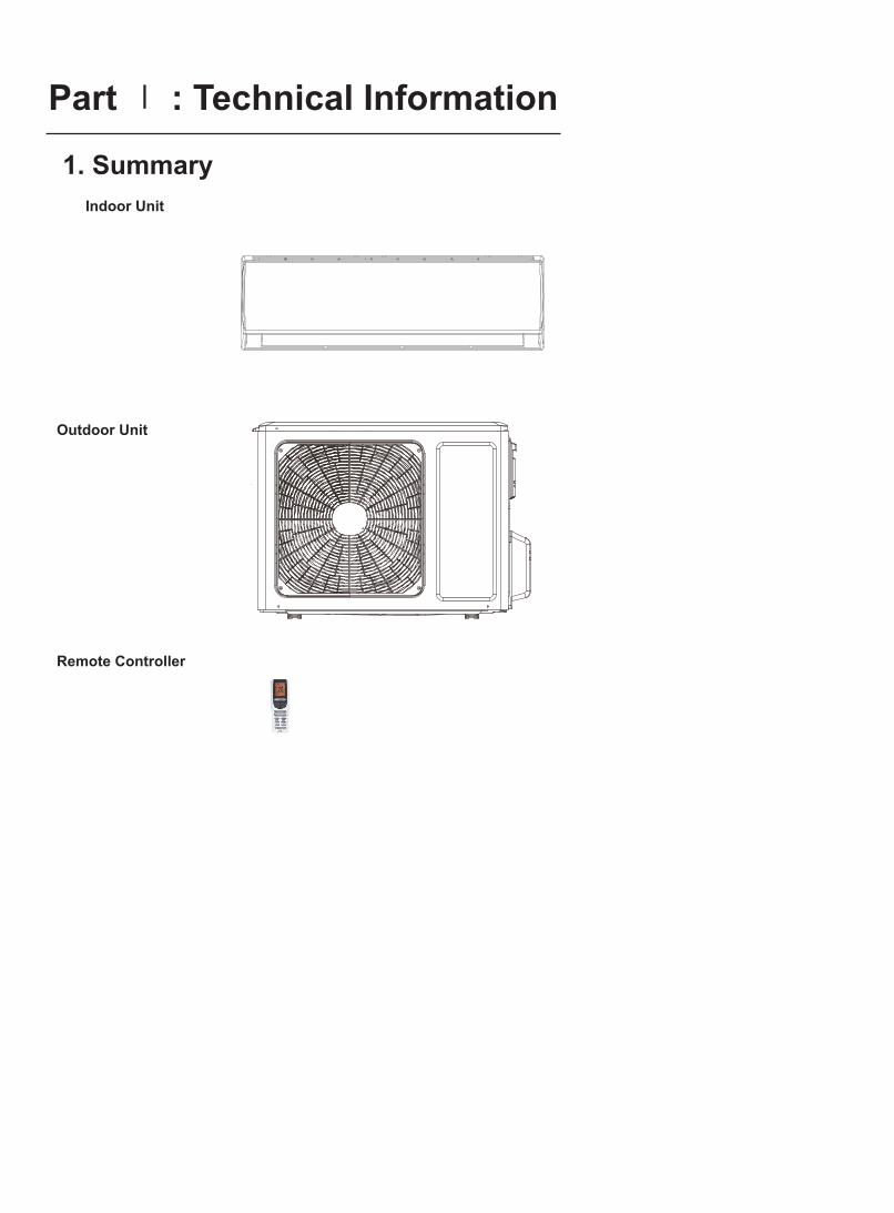
1. Summary
Part Ⅰ : Technical Information
Indoor Unit
Outdoor Unit
Remote Controller
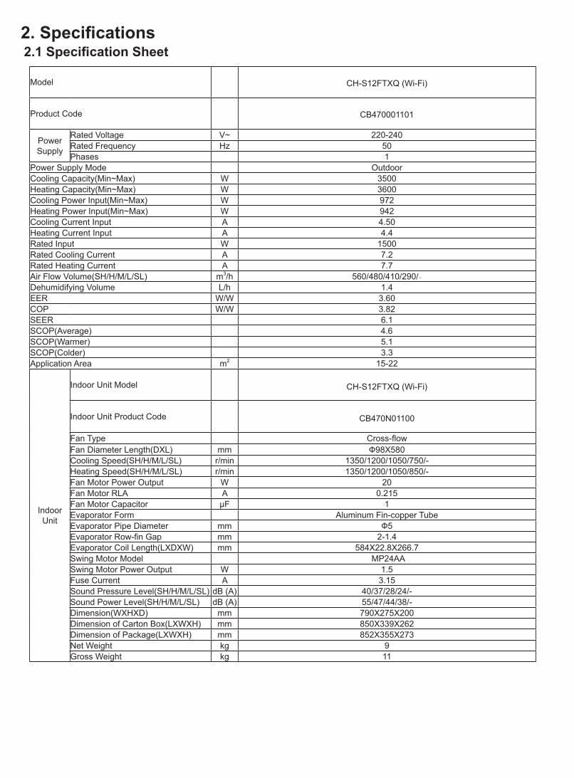
Model CH-S12FTXQ (Wi-Fi)
Product Code CB470001101
Power Supply
Rated Voltage V~ 220-240Rated Frequency Hz 50 Phases 1
Power Supply Mode OutdoorCooling Capacity(Min~Max) W 3500Heating Capacity(Min~Max) W 3600 Cooling Power Input(Min~Max) W 972 Heating Power Input(Min~Max) W 942 Cooling Current Input A 4.50 Heating Current Input A 4.4 Rated Input W 1500 Rated Cooling Current A 7.2 Rated Heating Current A 7.7Air Flow Volume(SH/H/M/L/SL) m3/h 560/480/410/290/-Dehumidifying Volume L/h 1.4EER W/W 3.60COP W/W 3.82SEER 6.1SCOP(Average) 4.6SCOP(Warmer) 5.1SCOP(Colder) 3.3Application Area m2 15-22
Indoor Unit
Indoor Unit Model CH-S12FTXQ (Wi-Fi)
Indoor Unit Product Code CB470N01100
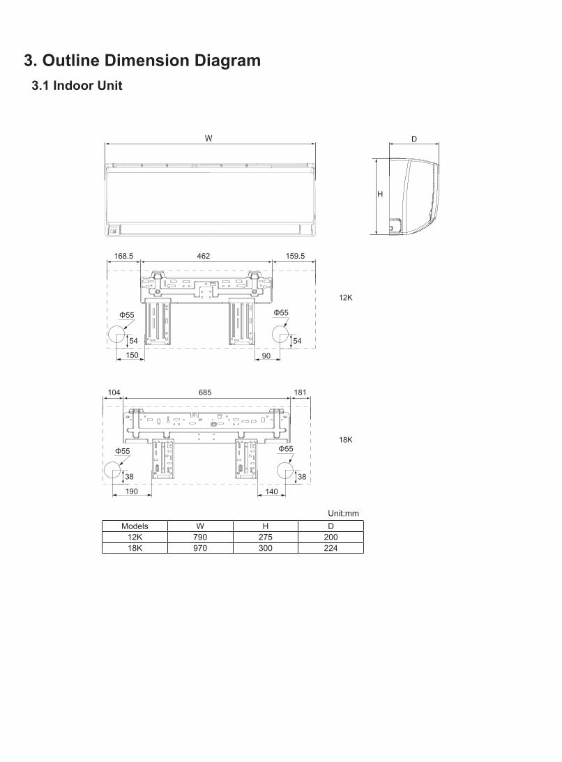
Fan Type Cross-flowFan Diameter Length(DXL) mm Ф98X580Cooling Speed(SH/H/M/L/SL) r/min 1350/1200/1050/750/-Heating Speed(SH/H/M/L/SL) r/min 1350/1200/1050/850/-Fan Motor Power Output W 20Fan Motor RLA A 0.215Fan Motor Capacitor μF 1Evaporator Form Aluminum Fin-copper TubeEvaporator Pipe Diameter mm Ф5Evaporator Row-fin Gap mm 2-1.4Evaporator Coil Length(LXDXW) mm 584X22.8X266.7Swing Motor Model MP24AASwing Motor Power Output W 1.5Fuse Current A 3.15Sound Pressure Level(SH/H/M/L/SL) dB (A) 40/37/28/24/-Sound Power Level(SH/H/M/L/SL) dB (A) 55/47/44/38/-Dimension(WXHXD) mm 790X275X200Dimension of Carton Box(LXWXH) mm 850X339X262Dimension of Package(LXWXH) mm 852X355X273Net Weight kg 9Gross Weight kg 11
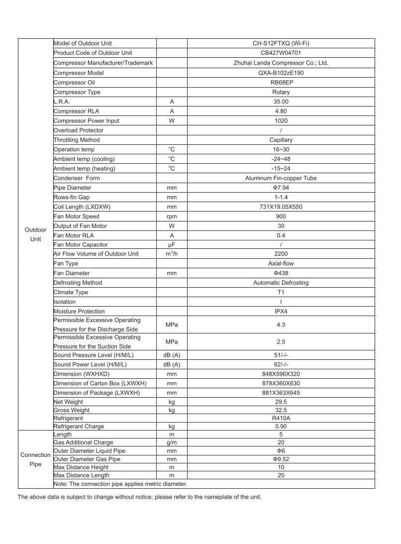
Compressor Model QXA-B102zE190Compressor Oil RB68EPCompressor Type RotaryL.R.A. A 35.00Compressor RLA A 4.80Compressor Power Input W 1020 Overload Protector /Throttling Method CapillaryOperation temp oC 16~30Ambient temp (cooling) oC -24~48Ambient temp (heating) oC -15~24Condenser Form Aluminum Fin-copper TubePipe Diameter mm Ф7.94Rows-fin Gap mm 1-1.4Coil Length (LXDXW) mm 731X19.05X550Fan Motor Speed rpm 900 Output of Fan Motor W 30 Fan Motor RLA A 0.4Fan Motor Capacitor μF /Air Flow Volume of Outdoor Unit m3/h 2200 Fan Type Axial-flowFan Diameter mm Ф438 Defrosting Method Automatic DefrostingClimate Type T1Isolation IMoisture Protection IPX4Permissible Excessive Operating Pressure for the Discharge Side
MPa 4.3
Permissible Excessive Operating Pressure for the Suction Side
MPa 2.5
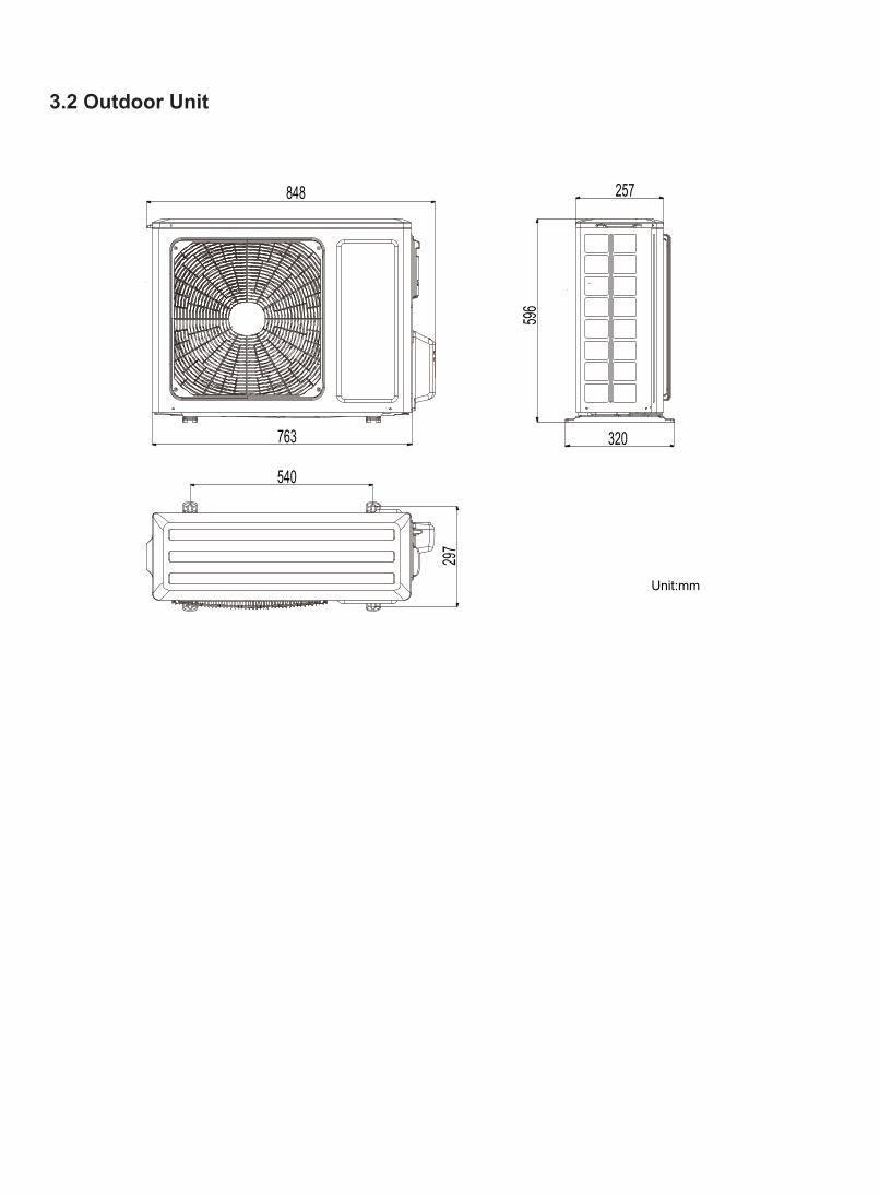
Sound Pressure Level (H/M/L) dB (A) 51/-/-Sound Power Level (H/M/L) dB (A) 62/-/- Dimension (WXHXD) mm 848X596X320Dimension of Carton Box (LXWXH) mm 878X360X630Dimension of Package (LXWXH) mm 881X363X645Net Weight kg 29.5Gross Weight kg 32.5Refrigerant R410ARefrigerant Charge kg 0.90
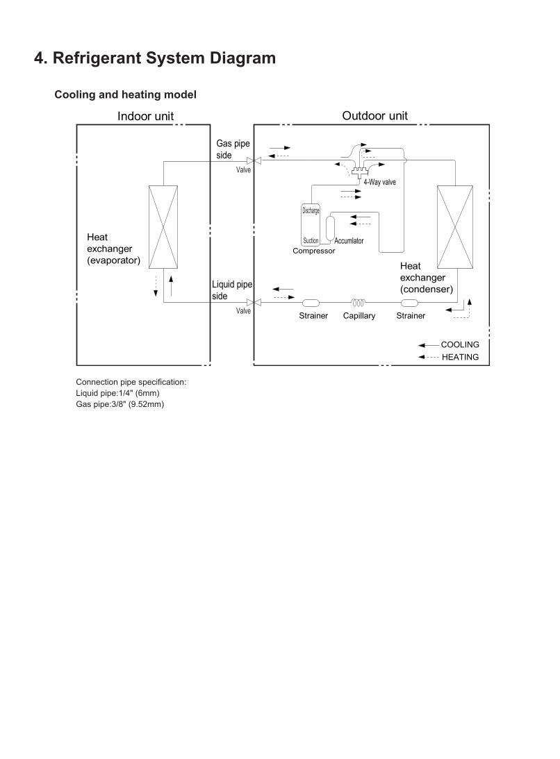
Connection Pipe
Length m 5 Gas Additional Charge g/m 20 Outer Diameter Liquid Pipe mm Ф6Outer Diameter Gas Pipe mm Ф9.52Max Distance Height m 10 Max Distance Length m 20 Note: The connection pipe applies metric diameter.
The above data is subject to change without notice; please refer to the nameplate of the unit.
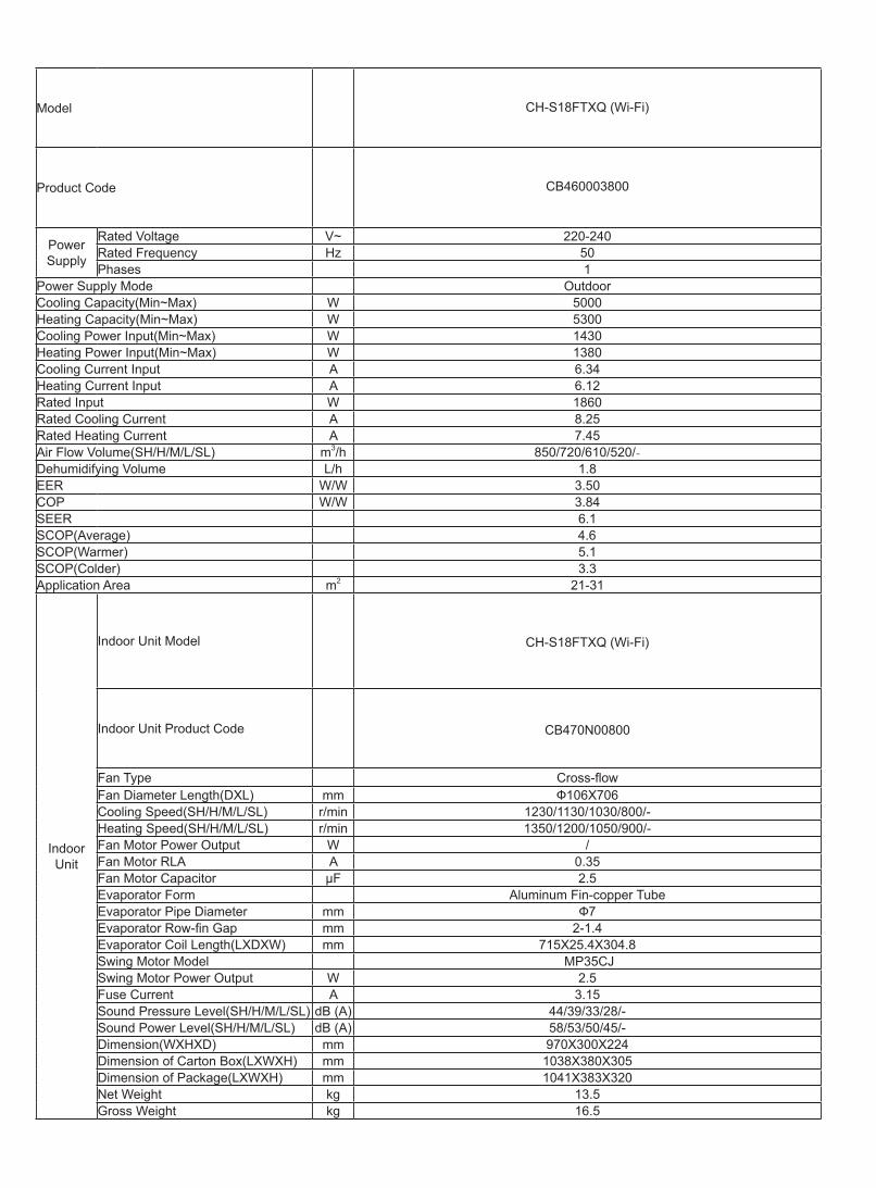
Model CH-S18FTXQ (Wi-Fi)
Product Code CB460003800
Power Supply
Rated Voltage V~ 220-240Rated Frequency Hz 50 Phases 1
Power Supply Mode OutdoorCooling Capacity(Min~Max) W 5000Heating Capacity(Min~Max) W 5300Cooling Power Input(Min~Max) W 1430 Heating Power Input(Min~Max) W 1380 Cooling Current Input A 6.34Heating Current Input A 6.12Rated Input W 1860 Rated Cooling Current A 8.25Rated Heating Current A 7.45Air Flow Volume(SH/H/M/L/SL) m3/h 850/720/610/520/-Dehumidifying Volume L/h 1.8EER W/W 3.50COP W/W 3.84SEER 6.1SCOP(Average) 4.6SCOP(Warmer) 5.1SCOP(Colder) 3.3Application Area m2 21-31
Indoor Unit
Indoor Unit Model CH-S18FTXQ (Wi-Fi)
Indoor Unit Product Code CB470N00800
Fan Type Cross-flowFan Diameter Length(DXL) mm Ф106X706Cooling Speed(SH/H/M/L/SL) r/min 1230/1130/1030/800/-Heating Speed(SH/H/M/L/SL) r/min 1350/1200/1050/900/-Fan Motor Power Output W /Fan Motor RLA A 0.35Fan Motor Capacitor μF 2.5Evaporator Form Aluminum Fin-copper TubeEvaporator Pipe Diameter mm Ф7Evaporator Row-fin Gap mm 2-1.4Evaporator Coil Length(LXDXW) mm 715X25.4X304.8Swing Motor Model MP35CJSwing Motor Power Output W 2.5Fuse Current A 3.15Sound Pressure Level(SH/H/M/L/SL) dB (A) 44/39/33/28/-Sound Power Level(SH/H/M/L/SL) dB (A) 58/53/50/45/-Dimension(WXHXD) mm 970X300X224Dimension of Carton Box(LXWXH) mm 1038X380X305Dimension of Package(LXWXH) mm 1041X383X320Net Weight kg 13.5Gross Weight kg 16.5
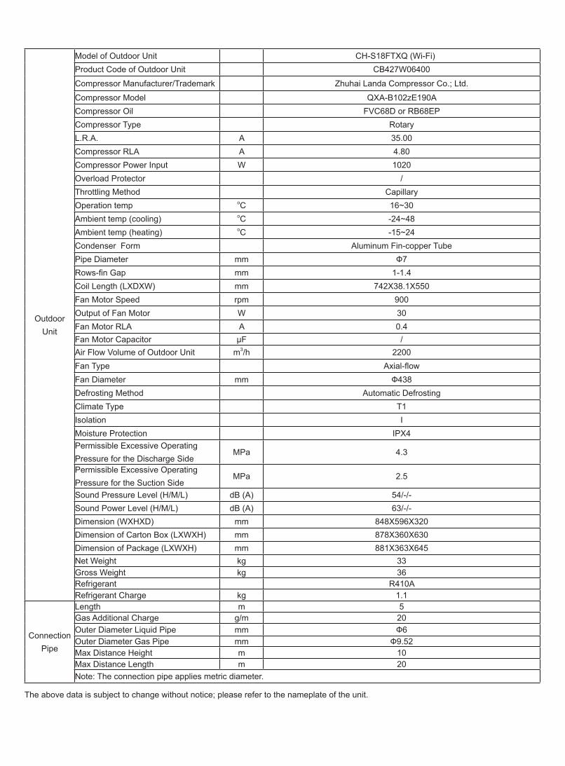
Compressor Model QXA-B102zE190ACompressor Oil FVC68D or RB68EPCompressor Type RotaryL.R.A. A 35.00Compressor RLA A 4.80Compressor Power Input W 1020 Overload Protector /Throttling Method CapillaryOperation temp oC 16~30Ambient temp (cooling) oC -24~48Ambient temp (heating) oC -15~24Condenser Form Aluminum Fin-copper TubePipe Diameter mm Ф7Rows-fin Gap mm 1-1.4Coil Length (LXDXW) mm 742X38.1X550Fan Motor Speed rpm 900 Output of Fan Motor W 30 Fan Motor RLA A 0.4Fan Motor Capacitor μF /Air Flow Volume of Outdoor Unit m3/h 2200 Fan Type Axial-flowFan Diameter mm Ф438 Defrosting Method Automatic DefrostingClimate Type T1Isolation IMoisture Protection IPX4Permissible Excessive Operating Pressure for the Discharge Side
MPa 4.3
Permissible Excessive Operating Pressure for the Suction Side
MPa 2.5
Sound Pressure Level (H/M/L) dB (A) 54/-/-Sound Power Level (H/M/L) dB (A) 63/-/- Dimension (WXHXD) mm 848X596X320Dimension of Carton Box (LXWXH) mm 878X360X630Dimension of Package (LXWXH) mm 881X363X645Net Weight kg 33Gross Weight kg 36Refrigerant R410ARefrigerant Charge kg 1.1
Connection Pipe
Length m 5 Gas Additional Charge g/m 20 Outer Diameter Liquid Pipe mm Ф6Outer Diameter Gas Pipe mm Ф9.52Max Distance Height m 10 Max Distance Length m 20Note: The connection pipe applies metric diameter.
The above data is subject to change without notice; please refer to the nameplate of the unit.
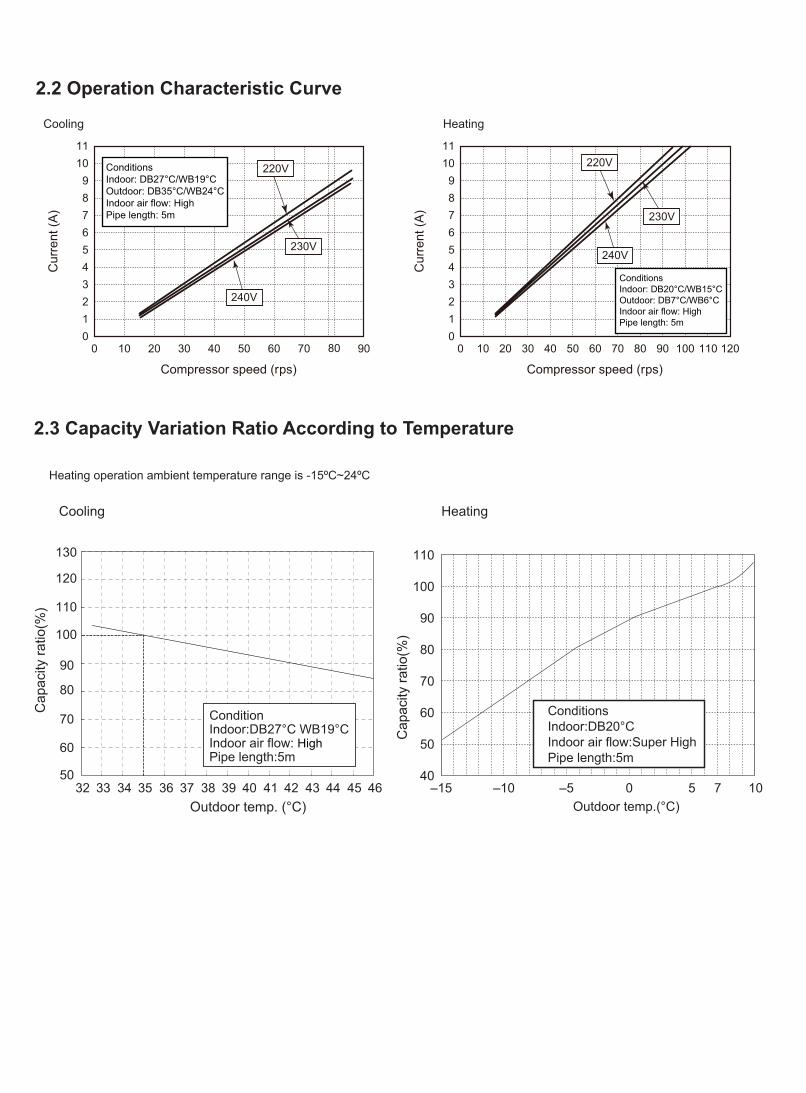
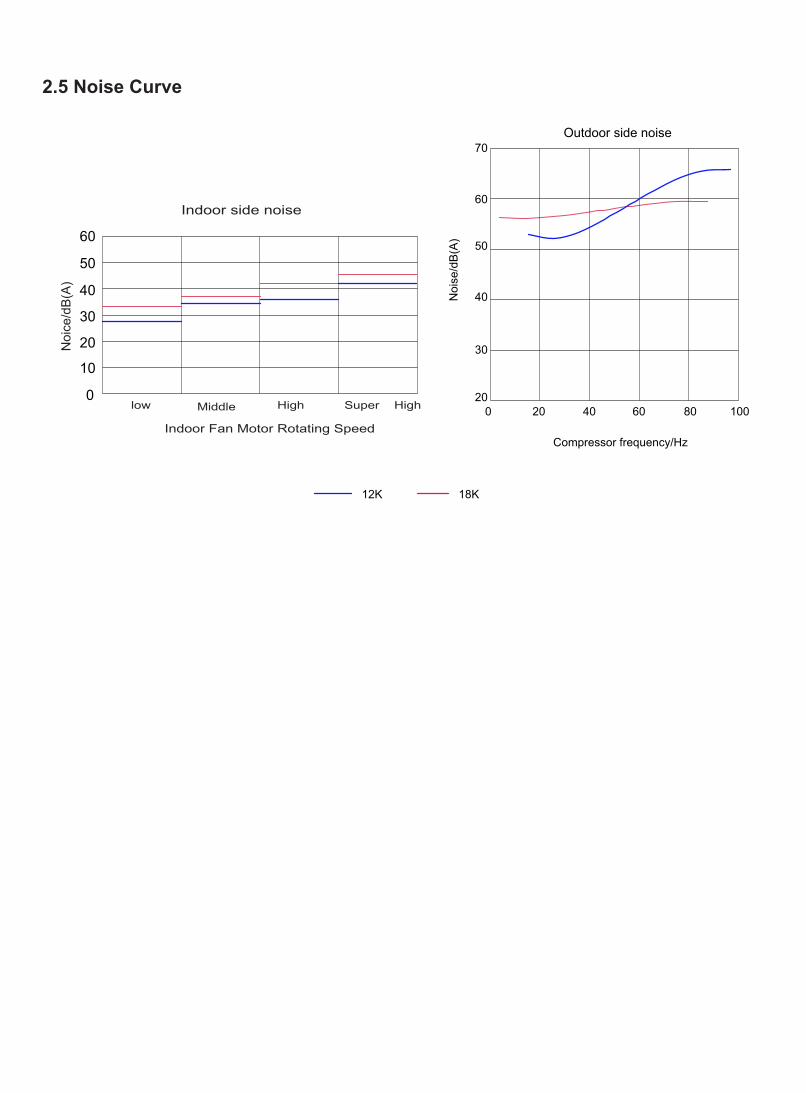
2.2 Operation Characteristic Curve
2.3 Capacity Variation Ratio According to Temperature
Conditions Indoor: DB27°C/WB19°C Outdoor: DB35°C/WB24°C Indoor air flow: High Pipe length: 5m
Conditions Indoor: DB27°C/WB19°C Outdoor: DB35°C/WB24°C Indoor air flow: High Pipe length: 5m
Conditions Indoor: DB20°C/WB15°C Outdoor: DB7°C/WB6°C Indoor air flow: High Pipe length: 5m
Conditions Indoor: DB20°C/WB15°C Outdoor: DB7°C/WB6°C Indoor air flow: High Pipe length: 5m
Cooling Heating
Cooling Heating
50
60
70
80
90
100
110
120
130
32 33 34 35 36 37 38 39 40 41 42 43 44 45 46
Cap
acity
ratio
(%)
Outdoor temp. (°C)
Cap
acity
ratio
(%)
–15 –10 –5
110
100
90
80
70
60
50
400 5 7 10
ConditionsIndoor:DB20°CIndoor air flow:Super HighPipe length:5m
Outdoor temp.(°C)
ConditionIndoor:DB27°C WB19°CIndoor air flow: HighPipe length:5m
Heating operation ambient temperature range is -15ºC~24ºC
32 33 34 35 36 37 38 39 4340 41 42
100105
95908580757065605550
ConditionsIndoor:DB27°C/WB19°CIndoor air flow:Super HighPipe length: 5m
Outdoor temp.(°C)
Cap
acity
ratio
(%)
Outdoor temp.(oC)
30
40
50
60
70
80
90
100
110
120
-22 -15 -10 -5 0 7 15 20 24
ConditionsIndoor:DB20°C/WB15°CIndoor air flow:Super HighPipe length: 5m
Cooling Heating
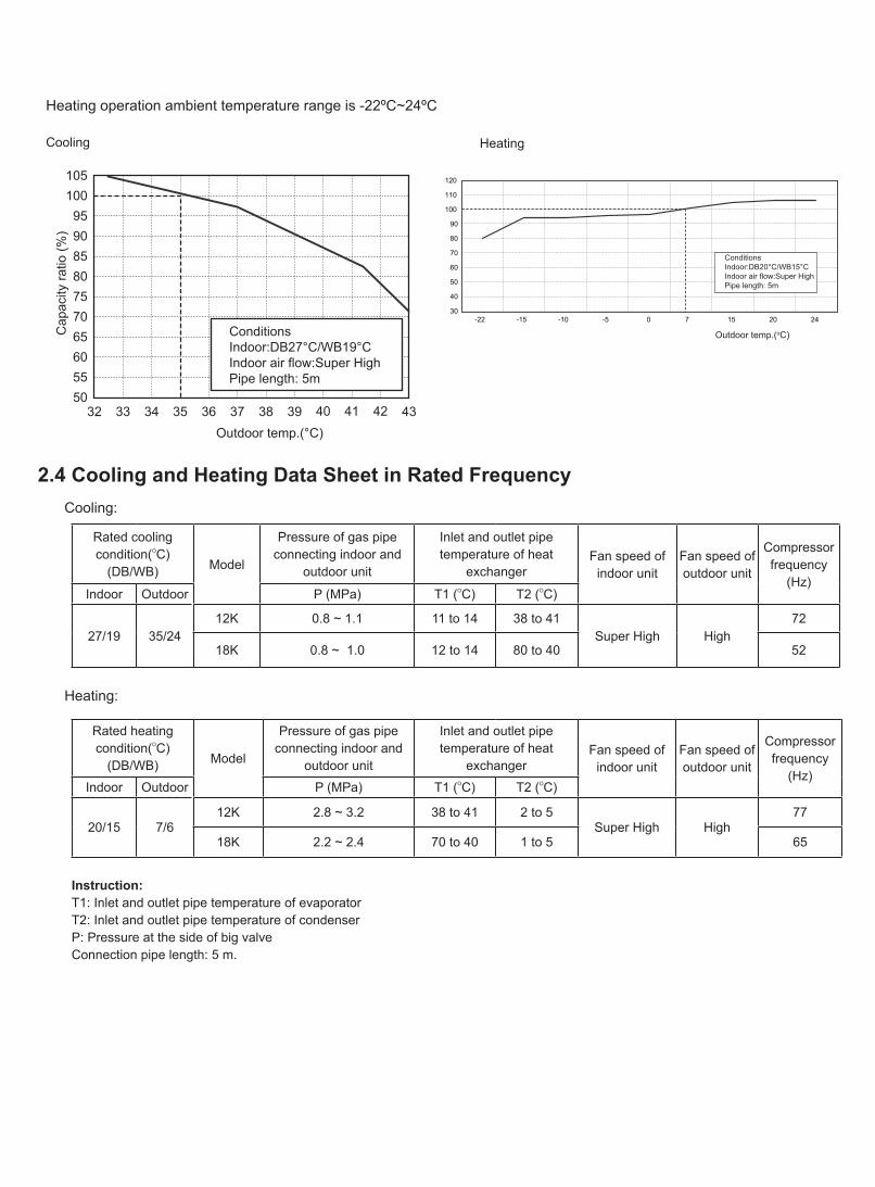
Heating operation ambient temperature range is -22ºC~24ºC
2.4 Cooling and Heating Data Sheet in Rated Frequency
Rated cooling condition(oC)
(DB/WB) Model
Pressure of gas pipe connecting indoor and
outdoor unit
Inlet and outlet pipe temperature of heat
exchangerFan speed of
indoor unitFan speed of outdoor unit
Compressorfrequency
(Hz)Indoor Outdoor P (MPa) T1 (oC) T2 (oC)
27/19 35/2412K 0.8 ~ 1.1 11 to 14 38 to 41
Super High High 72
18K 0.8 ~ 1.0 12 to 14 80 to 40 52
Rated heating condition(oC)
(DB/WB) Model
Pressure of gas pipe connecting indoor and
outdoor unit
Inlet and outlet pipe temperature of heat
exchangerFan speed of
indoor unitFan speed of outdoor unit
Compressorfrequency
(Hz)Indoor Outdoor P (MPa) T1 (oC) T2 (oC)
20/15 7/612K 2.8 ~ 3.2 38 to 41 2 to 5
Super High High 77
18K 2.2 ~ 2.4 70 to 40 1 to 5 65
Instruction:T1: Inlet and outlet pipe temperature of evaporatorT2: Inlet and outlet pipe temperature of condenserP: Pressure at the side of big valve Connection pipe length: 5 m.
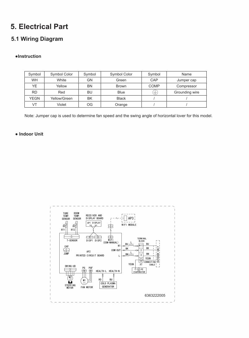
Symbol Symbol Color Symbol Symbol Color Symbol NameWH White GN Green CAP Jumper capYE Yellow BN Brown COMP Compressor
RD Red BU Blue Grounding wire
YEGN Yellow/Green BK Black / /
VT Violet OG Orange / /
Note: Jumper cap is used to determine fan speed and the swing angle of horizontal lover for this model.
6363222005
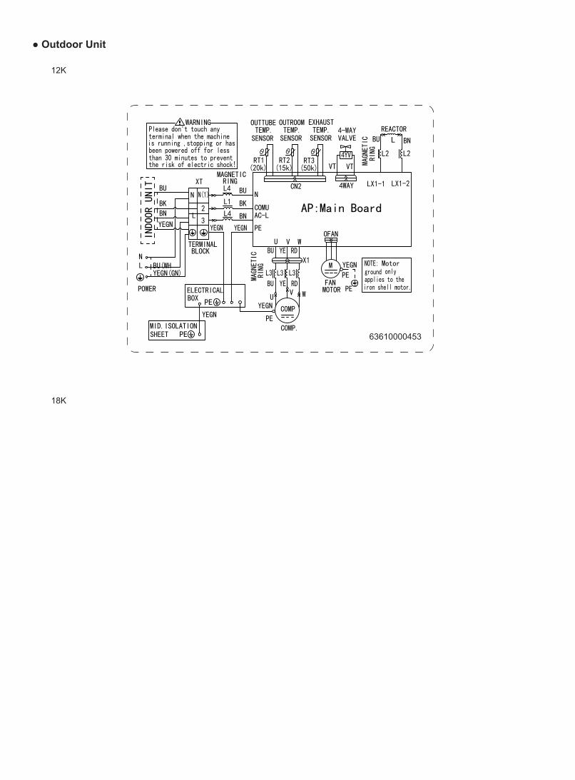
● Outdoor Unit
12K
18K
63610000453
These circuit diagrams are subject to change without notice, please refer to the one supplied with the unit.
N
63610000467
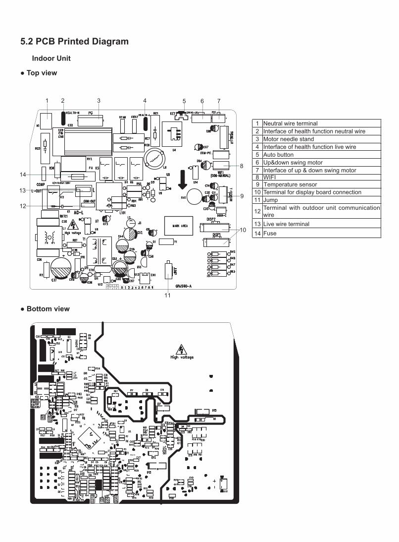
5.2 PCB Printed Diagram
Indoor Unit
● Top view
● Bottom view
1 Neutral wire terminal2 Interface of health function neutral wire3 Motor needle stand4 Interface of health function live wire5 Auto button6 Up&down swing motor7 Interface of up & down swing motor8 WIFI
Fuse
9 Temperature sensor10 Terminal for display board connection 11 Jump
12 Terminal with outdoor unit communication wire
1314
Live wire terminal
1 2 3 4 5 6 7
8
9
11
12
13
14
10
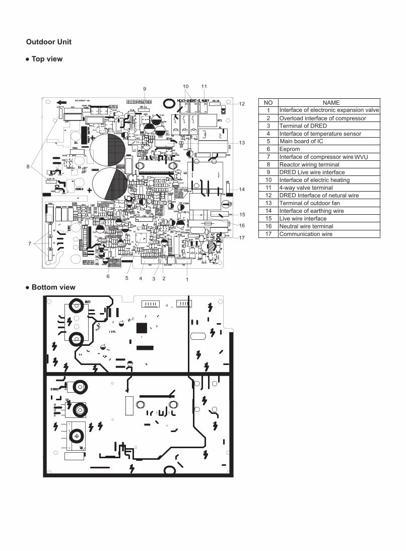
NO NAME1 Interface of electronic expansion valve 2 Overload interface of compressor 3 Terminal of DRED 4 Interface of temperature sensor 5 Main board of IC 6 Eeprom7 Interface of compressor wire WVU8 Reactor wiring terminal9 DRED Live wire interface
10 Interface of electric heating 11 4-way valve terminal12 DRED Interface of netural wire 13 Terminal of outdoor fan14 Interface of earthing wire15 Live wire interface16 Neutral wire terminal17 Communication wire
123456
7
8
9 10 11
12
13
14
15
16
17
Outdoor Unit
● Top view
● Bottom view
1. Select the installation location according to the require-ment of this manual.(See the requirements in installation part)2. Handle unit transportation with care; the unit should not be carried by only one person if it is more than 20kg.3. When installing the indoor unit and outdoor unit, a suffi-cient fixing bolt must be installed; make sure the installation support is firm.4. Ware safety belt if the height of working is above 2m.5. Use equipped components or appointed components dur-ing installation.6. Make sure no foreign objects are left in the unit after fin-ishing installation.
Electrical Safety Precautions:
7. Notes for Installation and Maintenance
Safety Precautions: Important!Please read the safety precautions carefully before installation and maintenance.The following contents are very important for installation and maintenance.
Please follow the instructions below.
●The installation or maintenance must accord with the instructions.●Comply with all national electrical codes and local electrical codes.●Pay attention to the warnings and cautions in this manual.●All installation and maintenance shall be performed by distributor or qualified person.●All electric work must be performed by a licensed technician according to local regulations and the instructions given in this manual.●Be caution during installation and maintenance. Prohibit incorrect operation to prevent electric shock, casualty and other accidents.
1. Cut off the power supply of air conditioner before checking and maintenance.2. The air condition must apply specialized circuit and prohibit share the same circuit with other appliances.3. The air conditioner should be installed in suitable location and ensure the power plug is touchable.4. Make sure each wiring terminal is connected firmly during installation and maintenance.5. Have the unit adequately grounded. The grounding wire cant be used for other purposes.6. Must apply protective accessories such as protective boards, cable-cross loop and wire clip.7. The live wire, neutral wire and grounding wire of power supply must be corresponding to the live wire, neutral wire and grounding wire of the air conditioner. 8. The power cord and power connection wires cant be pressed by hard objects.9. If power cord or connection wire is broken, it must be replaced by a qualified person.
1. Avoid contact between refrigerant and fire as it generates poisonous gas; Prohibit prolong the connection pipe by welding.2. Apply specified refrigerant only. Never have it mixed with any other refrigerant. Never have air remain in the refrigerant line as it may lead to rupture or other hazards.3. Make sure no refrigerant gas is leaking out when installation is completed.4. If there is refrigerant leakage, please take sufficient measure to minimize the density of refrigerant.5. Never touch the refrigerant piping or compressor without wearing glove to avoid scald or frostbite.
Warnings
Refrigerant Safety Precautions:
Improper installation may lead to fire hazard, explosion, electric shock or injury.
Installation Safety Precautions:
Part Ⅱ : Installation and Maintenance
10. If the power cord or connection wire is not long enough, please get the specialized power cord or connection wire from the manufacture or distributor. Prohibit prolong the wire by yourself.11. For the air conditioner without plug, an air switch must be installed in the circuit. The air switch should be all-pole parting and the contact parting distance should be more than 3mm.12. Make sure all wires and pipes are connected properly and the valves are opened before energizing.13. Check if there is electric leakage on the unit body. If yes, please eliminate the electric leakage.14. Replace the fuse with a new one of the same specification if it is burnt down; dont replace it with a cooper wire or conducting wire.15. If the unit is to be installed in a humid place, the circuit breaker must be installed.
Warnings
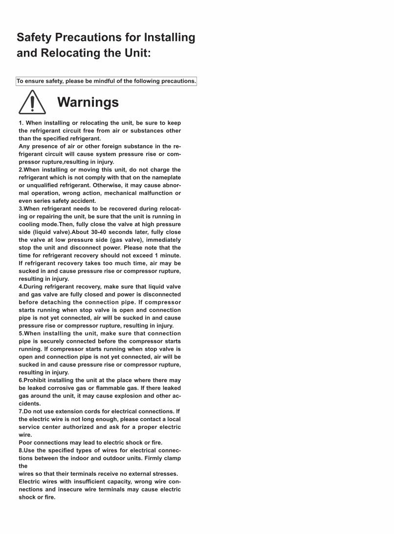
Safety Precautions for Installingand Relocating the Unit:
To ensure safety, please be mindful of the following precautions.
1. When installing or relocating the unit, be sure to keep the refrigerant circuit free from air or substances other than the specified refrigerant.Any presence of air or other foreign substance in the re-frigerant circuit will cause system pressure rise or com-pressor rupture,resulting in injury.2.When installing or moving this unit, do not charge the refrigerant which is not comply with that on the nameplate or unqualified refrigerant. Otherwise, it may cause abnor-mal operation, wrong action, mechanical malfunction or even series safety accident.3.When refrigerant needs to be recovered during relocat-ing or repairing the unit, be sure that the unit is running in cooling mode.Then, fully close the valve at high pressure side (liquid valve).About 30-40 seconds later, fully close the valve at low pressure side (gas valve), immediately stop the unit and disconnect power. Please note that the time for refrigerant recovery should not exceed 1 minute.If refrigerant recovery takes too much time, air may be sucked in and cause pressure rise or compressor rupture, resulting in injury.4.During refrigerant recovery, make sure that liquid valve and gas valve are fully closed and power is disconnected before detaching the connection pipe. If compressor starts running when stop valve is open and connection pipe is not yet connected, air will be sucked in and cause pressure rise or compressor rupture, resulting in injury.5.When installing the unit, make sure that connection pipe is securely connected before the compressor starts running. If compressor starts running when stop valve is open and connection pipe is not yet connected, air will be sucked in and cause pressure rise or compressor rupture, resulting in injury.6.Prohibit installing the unit at the place where there may be leaked corrosive gas or flammable gas. If there leaked gas around the unit, it may cause explosion and other ac-cidents.7.Do not use extension cords for electrical connections. Ifthe electric wire is not long enough, please contact a localservice center authorized and ask for a proper electric wire.Poor connections may lead to electric shock or fire.8.Use the specified types of wires for electrical connec-tions between the indoor and outdoor units. Firmly clamp thewires so that their terminals receive no external stresses.Electric wires with insufficient capacity, wrong wire con-nections and insecure wire terminals may cause electric shock or fire.
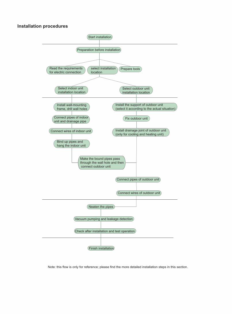
Prepare toolsRead the requirements for electric connection
select installation location
Select indoor unit installation location
Install wall-mounting frame, drill wall holes
Connect pipes of indoor unit and drainage pipe
Connect wires of indoor unit
Connect wires of outdoor unit
Bind up pipes and hang the indoor unit
Make the bound pipes pass through the wall hole and then connect outdoor unit
Neaten the pipes
Vacuum pumping and leakage detection
Check after installation and test operation
Finish installation
Note: this flow is only for reference; please find the more detailed installation steps in this section.
Select outdoor unit installation location
Install the support of outdoor unit(select it according to the actual situation)
Install drainage joint of outdoor unit (only for cooling and heating unit)
Connect pipes of outdoor unit
Start installation
Fix outdoor unit
Installation procedures
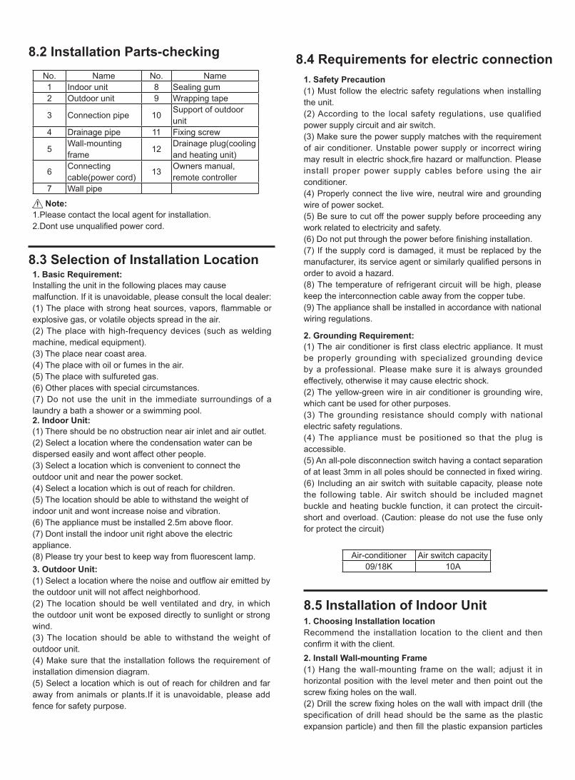
No. Name No. Name1 Indoor unit 8 Sealing gum2 Outdoor unit 9 Wrapping tape
3 Connection pipe 10Support of outdoor unit
4 Drainage pipe 11 Fixing screw
5Wall-mounting frame
12Drainage plug(cooling and heating unit)
6Connecting cable(power cord)
13Owners manual, remote controller
7 Wall pipe
1. Safety Precaution(1) Must follow the electric safety regulations when installing the unit.(2) According to the local safety regulations, use qualified power supply circuit and air switch.(3) Make sure the power supply matches with the requirement of air conditioner. Unstable power supply or incorrect wiring may result in electric shock,fire hazard or malfunction. Please install proper power supply cables before using the air conditioner.(4) Properly connect the live wire, neutral wire and grounding wire of power socket.(5) Be sure to cut off the power supply before proceeding any work related to electricity and safety.(6) Do not put through the power before finishing installation.(7) If the supply cord is damaged, it must be replaced by the manufacturer, its service agent or similarly qualified persons in order to avoid a hazard.(8) The temperature of refrigerant circuit will be high, please keep the interconnection cable away from the copper tube.(9) The appliance shall be installed in accordance with national wiring regulations.
8.2 Installation Parts-checking
8.3 Selection of Installation Location
8.4 Requirements for electric connection
8.5 Installation of Indoor Unit
1.Please contact the local agent for installation.2.Dont use unqualified power cord.
1. Basic Requirement:Installing the unit in the following places may cause malfunction. If it is unavoidable, please consult the local dealer:(1) The place with strong heat sources, vapors, flammable or explosive gas, or volatile objects spread in the air.(2) The place with high-frequency devices (such as welding machine, medical equipment).(3) The place near coast area.(4) The place with oil or fumes in the air.(5) The place with sulfureted gas.(6) Other places with special circumstances.(7) Do not use the unit in the immediate surroundings of a laundry a bath a shower or a swimming pool.
2. Grounding Requirement:(1) The air conditioner is first class electric appliance. It must be properly grounding with specialized grounding device by a professional. Please make sure it is always grounded effectively, otherwise it may cause electric shock.(2) The yellow-green wire in air conditioner is grounding wire, which cant be used for other purposes.(3) The grounding resistance should comply with national electric safety regulations.(4) The appliance must be positioned so that the plug is accessible.(5) An all-pole disconnection switch having a contact separation of at least 3mm in all poles should be connected in fixed wiring.(6) Including an air switch with suitable capacity, please note the following table. Air switch should be included magnet buckle and heating buckle function, it can protect the circuit-short and overload. (Caution: please do not use the fuse only for protect the circuit)
1. Choosing Installation IocationRecommend the installation location to the client and then confirm it with the client.2. Install Wall-mounting Frame(1) Hang the wall-mounting frame on the wall; adjust it in horizontal position with the level meter and then point out the screw fixing holes on the wall.(2) Drill the screw fixing holes on the wall with impact drill (the specification of drill head should be the same as the plastic expansion particle) and then fill the plastic expansion particles
2. Indoor Unit:(1) There should be no obstruction near air inlet and air outlet.(2) Select a location where the condensation water can be dispersed easily and wont affect other people.(3) Select a location which is convenient to connect the outdoor unit and near the power socket.(4) Select a location which is out of reach for children.(5) The location should be able to withstand the weight of indoor unit and wont increase noise and vibration.(6) The appliance must be installed 2.5m above floor.(7) Dont install the indoor unit right above the electric appliance.(8) Please try your best to keep way from fluorescent lamp.3. Outdoor Unit:(1) Select a location where the noise and outflow air emitted by the outdoor unit will not affect neighborhood.(2) The location should be well ventilated and dry, in which the outdoor unit wont be exposed directly to sunlight or strong wind.(3) The location should be able to withstand the weight of outdoor unit.(4) Make sure that the installation follows the requirement of installation dimension diagram.(5) Select a location which is out of reach for children and far away from animals or plants.If it is unavoidable, please add fence for safety purpose.
Refer to the following table for wrench moment of force:
Left Rear left
RightRear right
Cut offthe hole
Left Right Drain hose
Insulating pipe
5-10°Φ55mm
Indoor Outdoor
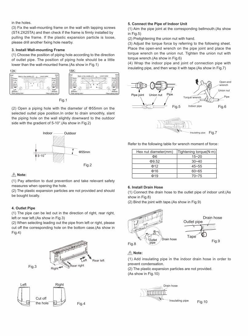
(1) Pay attention to dust prevention and take relevant safety measures when opening the hole.(2) The plastic expansion particles are not provided and should be bought locally.
(1) Add insulating pipe in the indoor drain hose in order to prevent condensation.(2) The plastic expansion particles are not provided.(As show in Fig.10)
Fig.1
Fig.2
Fig.5 Fig.6
Fig.7
Fig.8Fig.9
Fig.10
Fig.3
Fig.4
in the holes.(3) Fix the wall-mounting frame on the wall with tapping screws (ST4.2X25TA) and then check if the frame is firmly installed bypulling the frame. If the plastic expansion particle is loose, please drill another fixing hole nearby.
3. Install Wall-mounting Frame(1) Choose the position of piping hole according to the direction of outlet pipe. The position of piping hole should be a little lower than the wall-mounted frame.(As show in Fig.1)
5. Connect the Pipe of Indoor Unit(1) Aim the pipe joint at the corresponding bellmouth.(As show in Fig.5)(2) Pretightening the union nut with hand.(3) Adjust the torque force by referring to the following sheet. Place the open-end wrench on the pipe joint and place the torque wrench on the union nut. Tighten the union nut with torque wrench.(As show in Fig.6) (4) Wrap the indoor pipe and joint of connection pipe with insulating pipe, and then wrap it with tape.(As show in Fig.7)
6. Install Drain Hose(1) Connect the drain hose to the outlet pipe of indoor unit.(As show in Fig.8)(2) Bind the joint with tape.(As show in Fig.9)
4. Outlet Pipe(1) The pipe can be led out in the direction of right, rear right, left or rear left.(As show in Fig.3)(2) When selecting leading out the pipe from left or right, please cut off the corresponding hole on the bottom case.(As show in Fig.4)
(2) Open a piping hole with the diameter of Φ55mm on the selected outlet pipe position.In order to drain smoothly, slant the piping hole on the wall slightly downward to the outdoor side with the gradient of 5-10°.(As show in Fig.2)
Note:
Note:
12K:
Left
Wall
Φ55mmRight
Mark in the middle of it Level meter
Rear piping hole
Wall
Spaceto thewall
above150mm
Spaceto thewall
above150mm
Φ55mmRear piping hole
18K:
Left
Wall
Φ55mmRight
Mark in the middle of it Level meter
Rear piping hole
Wall
Spaceto thewall
above150mm
Spaceto thewall
above150mm
Φ55mmRear piping hole
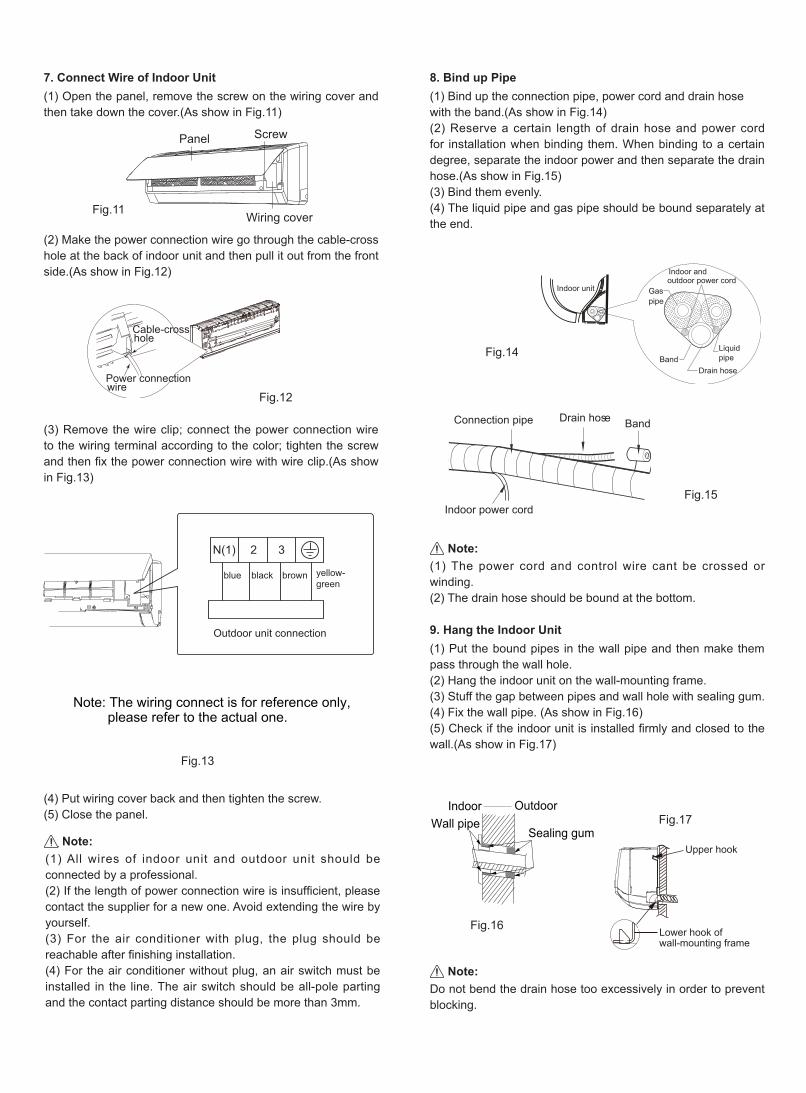
(4) Put wiring cover back and then tighten the screw.(5) Close the panel.
Indoor unit Gaspipe
Indoor andoutdoor power cord
Liquid pipe
Drain hoseBand
Drain hose BandConnection pipe
Indoor power cord
(1) All wires of indoor unit and outdoor unit should be connected by a professional.(2) If the length of power connection wire is insufficient, please contact the supplier for a new one. Avoid extending the wire by yourself. (3) For the air conditioner with plug, the plug should be reachable after finishing installation.(4) For the air conditioner without plug, an air switch must be installed in the line. The air switch should be all-pole parting and the contact parting distance should be more than 3mm.
(1) The power cord and control wire cant be crossed or winding.(2) The drain hose should be bound at the bottom.
Do not bend the drain hose too excessively in order to prevent blocking.
7. Connect Wire of Indoor Unit(1) Open the panel, remove the screw on the wiring cover and then take down the cover.(As show in Fig.11)
8. Bind up Pipe(1) Bind up the connection pipe, power cord and drain hose with the band.(As show in Fig.14)(2) Reserve a certain length of drain hose and power cord for installation when binding them. When binding to a certain degree, separate the indoor power and then separate the drain hose.(As show in Fig.15)(3) Bind them evenly.(4) The liquid pipe and gas pipe should be bound separately at the end.
9. Hang the Indoor Unit(1) Put the bound pipes in the wall pipe and then make them pass through the wall hole.(2) Hang the indoor unit on the wall-mounting frame.(3) Stuff the gap between pipes and wall hole with sealing gum.(4) Fix the wall pipe. (As show in Fig.16)(5) Check if the indoor unit is installed firmly and closed to the wall.(As show in Fig.17)
(2) Make the power connection wire go through the cable-cross hole at the back of indoor unit and then pull it out from the front side.(As show in Fig.12)
(3) Remove the wire clip; connect the power connection wire to the wiring terminal according to the color; tighten the screw and then fix the power connection wire with wire clip.(As show in Fig.13)
Note:
Note:
Note:
Indoor OutdoorWall pipe
Sealing gumUpper hook
Lower hook ofwall-mounting frame
Fig.11
Fig.12
Fig.13
Fig.14
Fig.15
Fig.16
Fig.17
Power connectionwire
Cable-crosshole
Note: The wiring connect is for reference only, please refer to the actual one.
blue black brown yellow-green
Connect to outdoor unit
2 3
Wiring cover
ScrewPanel
N(1) 2 3
blue brownblack yellow-green
Outdoor unit connection
Big handle
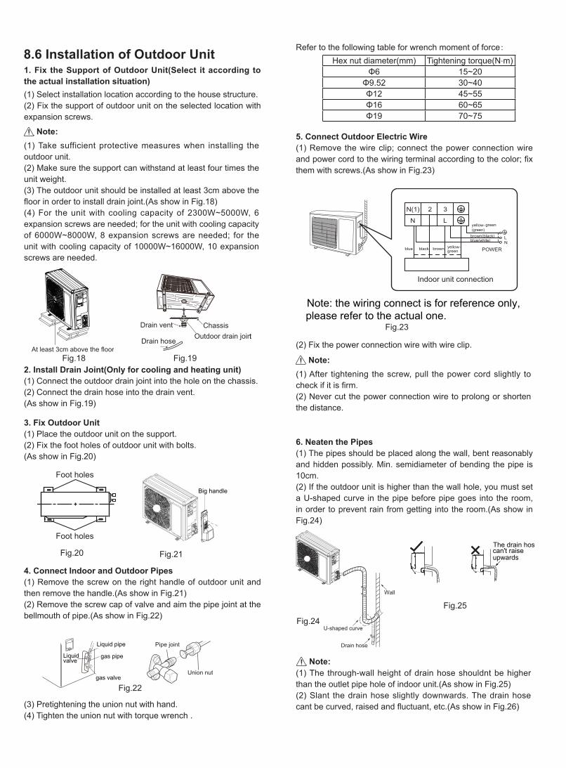
(1) Take sufficient protective measures when installing the outdoor unit.(2) Make sure the support can withstand at least four times the unit weight.(3) The outdoor unit should be installed at least 3cm above the floor in order to install drain joint.(As show in Fig.18)(4) For the unit with cooling capacity of 2300W~5000W, 6 expansion screws are needed; for the unit with cooling capacity of 6000W~8000W, 8 expansion screws are needed; for the unit with cooling capacity of 10000W~16000W, 10 expansion screws are needed.
(1) After tightening the screw, pull the power cord slightly to check if it is firm.(2) Never cut the power connection wire to prolong or shorten the distance.
(1) The through-wall height of drain hose shouldnt be higher than the outlet pipe hole of indoor unit.(As show in Fig.25)(2) Slant the drain hose slightly downwards. The drain hose cant be curved, raised and fluctuant, etc.(As show in Fig.26)
Note:
Note:
Note:
The drain hoscan't raiseupwards
gas pipe
Liquid pipe
Liquidvalve
gas valveUnion nut
Pipe joint
Foot holes
Foot holes
ChassisOutdoor drain joint
Drain hose
Drain vent
8.6 Installation of Outdoor Unit1. Fix the Support of Outdoor Unit(Select it according to the actual installation situation)(1) Select installation location according to the house structure.(2) Fix the support of outdoor unit on the selected location with expansion screws.
5. Connect Outdoor Electric Wire(1) Remove the wire clip; connect the power connection wire and power cord to the wiring terminal according to the color; fix them with screws.(As show in Fig.23)
6. Neaten the Pipes(1) The pipes should be placed along the wall, bent reasonably and hidden possibly. Min. semidiameter of bending the pipe is 10cm.(2) If the outdoor unit is higher than the wall hole, you must set a U-shaped curve in the pipe before pipe goes into the room, in order to prevent rain from getting into the room.(As show in Fig.24)
(2) Fix the power connection wire with wire clip.
2. Install Drain Joint(Only for cooling and heating unit)(1) Connect the outdoor drain joint into the hole on the chassis.(2) Connect the drain hose into the drain vent.(As show in Fig.19)
3. Fix Outdoor Unit(1) Place the outdoor unit on the support.(2) Fix the foot holes of outdoor unit with bolts.(As show in Fig.20)
4. Connect Indoor and Outdoor Pipes(1) Remove the screw on the right handle of outdoor unit and then remove the handle.(As show in Fig.21)(2) Remove the screw cap of valve and aim the pipe joint at the bellmouth of pipe.(As show in Fig.22)
(3) Pretightening the union nut with hand.(4) Tighten the union nut with torque wrench .
Refer to the following table for wrench moment of force:
Fig.18 Fig.19
Fig.20 Fig.21
Fig.22
Fig.23
Fig.24
Fig.25
U-shaped curve
Wall
Drain hose
Note: the wiring connect is for reference only,please refer to the actual one.
Indoor unit connection
LN
2 3N(1)
NL
POWERblue
blue(white)brown(black)
black brown yellow-green
yellow-(green)
green
At least 3cm above the floor
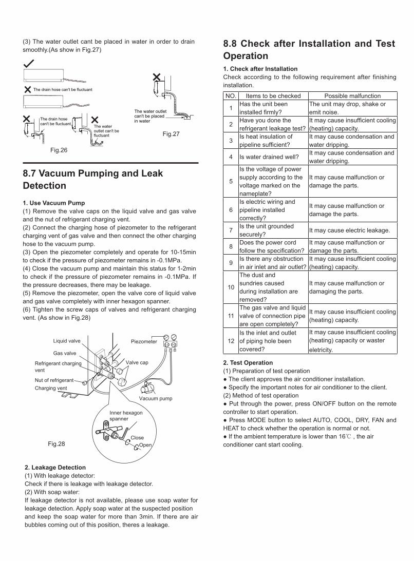
(3) The water outlet cant be placed in water in order to drain smoothly.(As show in Fig.27)
Liquid valve
Gas valve
Refrigerant chargingvent
Nut of refrigerantCharging vent
Vacuum pump
Piezometer
Valve cap
Lo Hi
Inner hexagonspanner
OpenClose
The drain hose can't be fluctuant
The drain hosecan't be fluctuant The water
outlet can't befluctuant
The water outlet can't be placedin water
1. Use Vacuum Pump(1) Remove the valve caps on the liquid valve and gas valve and the nut of refrigerant charging vent.(2) Connect the charging hose of piezometer to the refrigerant charging vent of gas valve and then connect the other charging hose to the vacuum pump.(3) Open the piezometer completely and operate for 10-15min to check if the pressure of piezometer remains in -0.1MPa.(4) Close the vacuum pump and maintain this status for 1-2min to check if the pressure of piezometer remains in -0.1MPa. If the pressure decreases, there may be leakage.(5) Remove the piezometer, open the valve core of liquid valve and gas valve completely with inner hexagon spanner.(6) Tighten the screw caps of valves and refrigerant charging vent. (As show in Fig.28)
1. Check after InstallationCheck according to the following requirement after finishing installation.
2. Test Operation(1) Preparation of test operation● The client approves the air conditioner installation.● Specify the important notes for air conditioner to the client.(2) Method of test operation● Put through the power, press ON/OFF button on the remote controller to start operation.● Press MODE button to select AUTO, COOL, DRY, FAN and HEAT to check whether the operation is normal or not.● If the ambient temperature is lower than 16℃ , the air conditioner cant start cooling.
2. Leakage Detection(1) With leakage detector:Check if there is leakage with leakage detector.(2) With soap water:If leakage detector is not available, please use soap water for leakage detection. Apply soap water at the suspected positionand keep the soap water for more than 3min. If there are air bubbles coming out of this position, theres a leakage.
8.7 Vacuum Pumping and Leak Detection
8.8 Check after Installation and Test Operation
Fig.26
Fig.27
Fig.28
NO. Items to be checked Possible malfunction
1Has the unit been installed firmly?
The unit may drop, shake or emit noise.
2Have you done the refrigerant leakage test?
It may cause insufficient cooling (heating) capacity.
3Is heat insulation of pipeline sufficient?
It may cause condensation and water dripping.
4 Is water drained well?It may cause condensation and water dripping.
5
Is the voltage of power supply according to the voltage marked on the nameplate?
It may cause malfunction or damage the parts.
6Is electric wiring and pipeline installed correctly?
It may cause malfunction or damage the parts.
7Is the unit grounded securely?
It may cause electric leakage.
8Does the power cord follow the specification?
It may cause malfunction or damage the parts.
9Is there any obstruction in air inlet and air outlet?
It may cause insufficient cooling (heating) capacity.
10
The dust and sundries caused during installation are removed?
It may cause malfunction or damaging the parts.
11The gas valve and liquid valve of connection pipe are open completely?
It may cause insufficient cooling (heating) capacity.
12Is the inlet and outlet of piping hole been covered?
It may cause insufficient cooling(heating) capacity or waster eletricity.
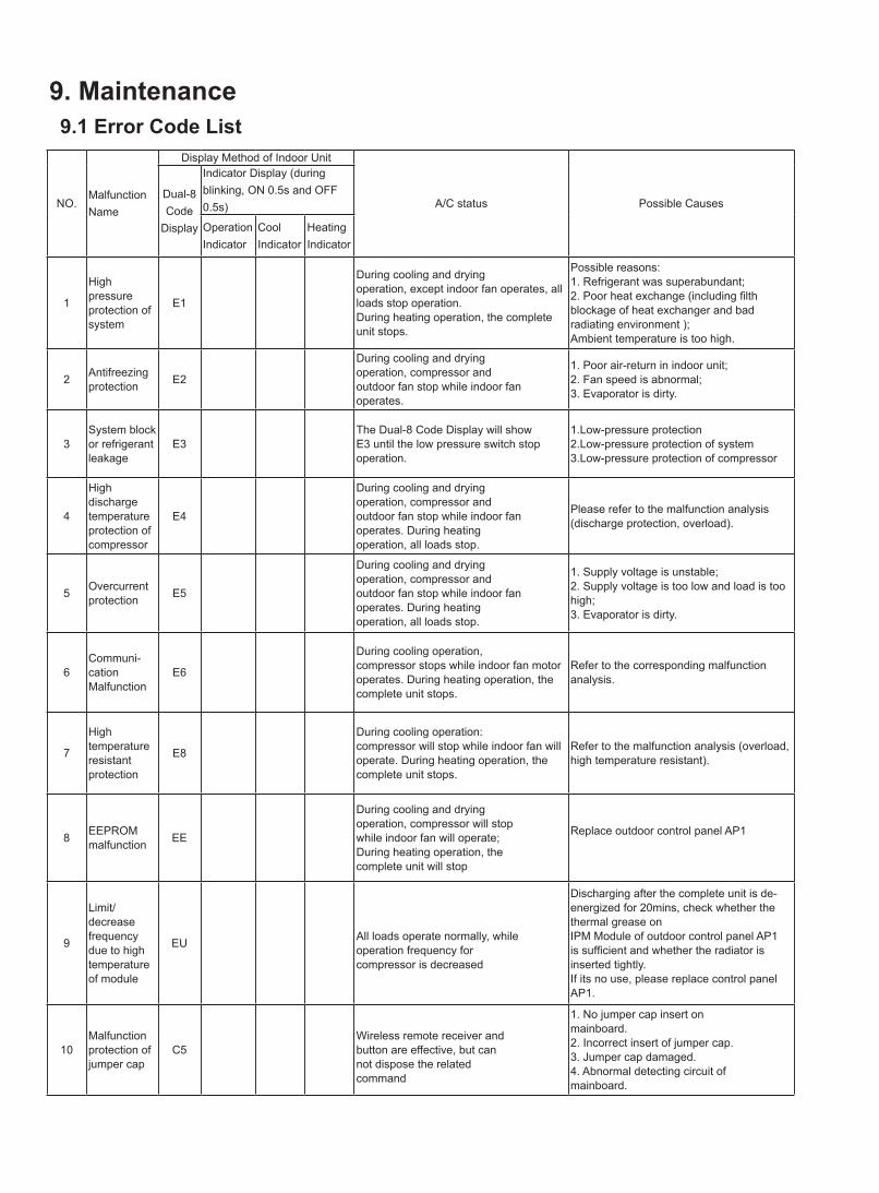
9. Maintenance9.1 Error Code List
NO.MalfunctionName
Display Method of Indoor Unit
A/C status Possible Causes Dual-8Code
Display
Indicator Display (during blinking, ON 0.5s and OFF 0.5s)
OperationIndicator
CoolIndicator
HeatingIndicator
1
High pressureprotection of system
E1
During cooling and dryingoperation, except indoor fan operates, all loads stop operation.During heating operation, the complete unit stops.
Possible reasons: 1. Refrigerant was superabundant; 2. Poor heat exchange (including filth blockage of heat exchanger and bad radiating environment );Ambient temperature is too high.
2 Antifreezingprotection E2
During cooling and dryingoperation, compressor andoutdoor fan stop while indoor fan operates.
1. Poor air-return in indoor unit;2. Fan speed is abnormal;3. Evaporator is dirty.
3System block or refrigerant leakage
E3The Dual-8 Code Display will show E3 until the low pressure switch stop operation.
1.Low-pressure protection 2.Low-pressure protection of system 3.Low-pressure protection of compressor
4
High dischargetemperatureprotection ofcompressor
E4
During cooling and dryingoperation, compressor andoutdoor fan stop while indoor fan operates. During heatingoperation, all loads stop.
Please refer to the malfunction analysis (discharge protection, overload).
5 Overcurrentprotection E5
During cooling and dryingoperation, compressor andoutdoor fan stop while indoor fan operates. During heatingoperation, all loads stop.
1. Supply voltage is unstable;2. Supply voltage is too low and load is too high;3. Evaporator is dirty.
6Communi-cationMalfunction
E6
During cooling operation,compressor stops while indoor fan motor operates. During heating operation, the complete unit stops.
Refer to the corresponding malfunction analysis.
7
Hightemperatureresistantprotection
E8
During cooling operation:compressor will stop while indoor fan will operate. During heating operation, the complete unit stops.
Refer to the malfunction analysis (overload, high temperature resistant).
8 EEPROMmalfunction EE
During cooling and dryingoperation, compressor will stopwhile indoor fan will operate;During heating operation, thecomplete unit will stop
Replace outdoor control panel AP1
9
Limit/decreasefrequency due to hightemperature of module
EU All loads operate normally, whileoperation frequency forcompressor is decreased
Discharging after the complete unit is de-energized for 20mins, check whether the thermal grease onIPM Module of outdoor control panel AP1 is sufficient and whether the radiator is inserted tightly.If its no use, please replace control panel AP1.
10Malfunctionprotection ofjumper cap
C5Wireless remote receiver andbutton are effective, but cannot dispose the relatedcommand
1. No jumper cap insert onmainboard.2. Incorrect insert of jumper cap.3. Jumper cap damaged.4. Abnormal detecting circuit ofmainboard.
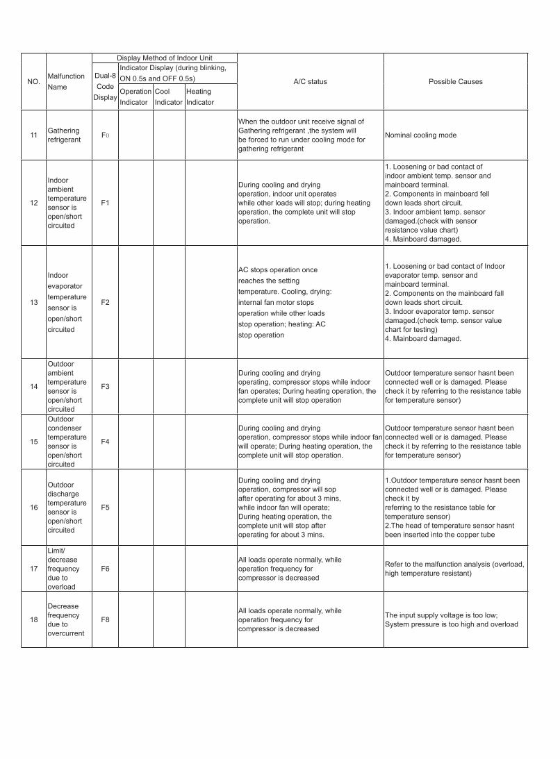
NO.MalfunctionName
Display Method of Indoor Unit
A/C status Possible Causes Dual-8Code
Display
Indicator Display (during blinking, ON 0.5s and OFF 0.5s)
OperationIndicator
CoolIndicator
HeatingIndicator
11 Gathering refrigerant F0
When the outdoor unit receive signal of Gathering refrigerant ,the system will be forced to run under cooling mode for gathering refrigerant
During cooling and dryingoperation, indoor unit operateswhile other loads will stop; during heating operation, the complete unit will stop operation.
1. Loosening or bad contact ofindoor ambient temp. sensor andmainboard terminal.2. Components in mainboard felldown leads short circuit.3. Indoor ambient temp. sensordamaged.(check with sensorresistance value chart)4. Mainboard damaged.
AC stops operation oncereaches the settingtemperature. Cooling, drying:internal fan motor stopsoperation while other loadsstop operation; heating: ACstop operation
1. Loosening or bad contact of Indoorevaporator temp. sensor andmainboard terminal.2. Components on the mainboard falldown leads short circuit.3. Indoor evaporator temp. sensordamaged.(check temp. sensor valuechart for testing)4. Mainboard damaged.
During cooling and dryingoperation, compressor will sopafter operating for about 3 mins,while indoor fan will operate;During heating operation, thecomplete unit will stop afteroperating for about 3 mins.
1.Outdoor temperature sensor hasnt been connected well or is damaged. Please check it byreferring to the resistance table for temperature sensor)2.The head of temperature sensor hasnt been inserted into the copper tube
17
Limit/decreasefrequency due tooverload
F6All loads operate normally, whileoperation frequency forcompressor is decreased
Refer to the malfunction analysis (overload, high temperature resistant)
18
Decreasefrequency due toovercurrent
F8All loads operate normally, whileoperation frequency forcompressor is decreased
The input supply voltage is too low;System pressure is too high and overload
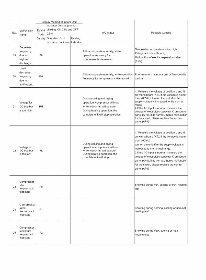
NO.MalfunctionName
Display Method of Indoor Unit
A/C status Possible Causes Dual-8Code
Display
Indicator Display (during blinking, ON 0.5s and OFF 0.5s)
OperationIndicator
CoolIndicator
HeatingIndicator
19
Decreasefrequency due tohigh airdischarge
F9All loads operate normally, whileoperation frequency forcompressor is decreased
Overload or temperature is too high; Refrigerant is insufficient;Malfunction of electric expansion valve (EKV)
20
Limit/decreasefrequency due toantifreezing
FHAll loads operate normally, while operation frequency for compressor is decreased
Poor air-return in indoor unit or fan speed is too low
21Voltage for DC bus-bar is too high
PH
During cooling and dryingoperation, compressor will stopwhile indoor fan will operate;During heating operation, thecomplete unit will stop operation.
1. Measure the voltage of position L and N on wiring board (XT), if the voltage is higher than 265VAC, turn on the unit after the supply voltage is increased to the normal range.2.If the AC input is normal, measure the voltage of electrolytic capacitor C on control panel (AP1), if its normal, theres malfunction for the circuit, please replace the control panel (AP1)
22Voltage of DC bus-bar is too low
PL
During cooling and dryingoperation, compressor will stopwhile indoor fan will operate;During heating operation, thecomplete unit will stop
1. Measure the voltage of position L and N on wiring board (XT), if the voltage is higher than 150VAC,turn on the unit after the supply voltage is increased to the normal range.2.If the AC input is normal, measure the voltage of electrolytic capacitor C on control panel (AP1), if its normal, theres malfunction for the circuit, please replace the control panel (AP1)
23
Compressor Min frequence in test state
P0Showing during min. cooling or min. heating test
24
Compressor rated frequence in test state
P1 Showing during nominal cooling or nominal heating test
25
Compressor maximum frequence in test state
P2Showing during max. cooling or max. heating test
NO.MalfunctionName
Display Method of Indoor Unit
A/C status Possible Causes Dual-8Code
Display
Indicator Display (during blinking, ON 0.5s and OFF 0.5s)
OperationIndicator
CoolIndicator
HeatingIndicator
26
Compressor intermediate frequence in test state
P3Showing during middle cooling or middle heating test
27
Overcurrentprotection ofphase current for compressor
P5
During cooling and dryingoperation, compressor will stopwhile indoor fan will operate;During heating operation, thecomplete unit will stop operation.
Refer to the malfunction analysis (IPM protection, loss of synchronism protection and overcurrent protection of phase current for compressor.
28
Chargingmalfunction of capacitor
PU
During cooling and dryingoperation, compressor will stopwhile indoor fan will operate;During heating operation, thecomplete unit will stop
Refer to the part three—charging malfunction analysis of capacitor
29
Malfunction of moduletemperaturesensor circuit
P7
During cooling and dryingoperation, compressor will stopwhile indoor fan will operate;During heating operation, thecomplete unit will stop
Replace outdoor control panel AP1
30Module hightemperatureprotection
P8
During cooling operation,compressor will stop while indoor fan will operate; During heating operation, the complete unit will stop
After the complete unit is de-energized for 20mins, check whether the thermal grease on IPM Module of outdoor control panel AP1 is sufficient and whether the radiator is inserted tightly. If its no use, please replace control panel AP1.
31Overloadprotection forcompressor
H3
During cooling and dryingoperation, compressor will stopwhile indoor fan will operate;During heating operation, thecomplete unit will stop operation.
1. Wiring terminal OVC-COMP is loosened. In normal state, the resistance for this terminal shouldbe less than 1ohm. 2.Refer to the malfunction analysis ( discharge protection, overload)
32IPM protection
H5
During cooling and dryingoperation, compressor will stopwhile indoor fan will operate;During heating operation, thecomplete unit will stop operation.
Refer to the malfunction analysis (IPM protection, loss of synchronism protection and overcurrent protection of phase current for compressor.
NO.MalfunctionName
Display Method of Indoor Unit
A/C status Possible Causes Dual-8Code
Display
Indicator Display (during blinking, ON 0.5s and OFF 0.5s)
OperationIndicator
CoolIndicator
HeatingIndicator
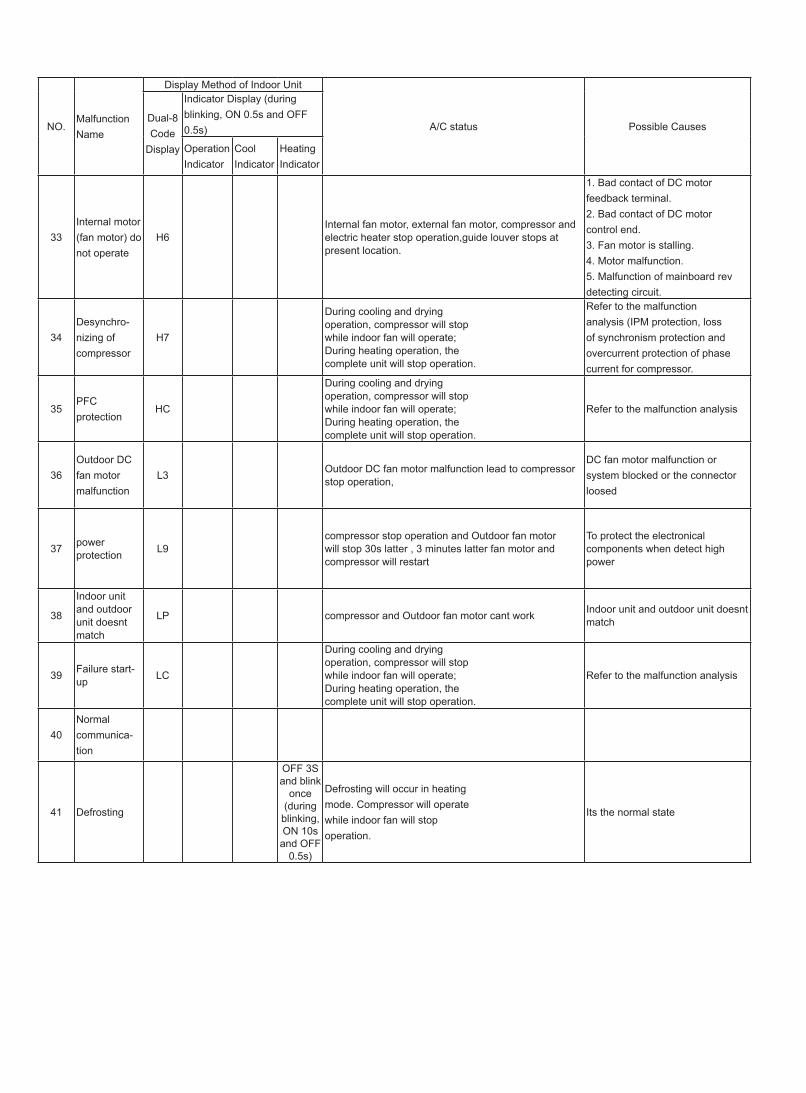
33Internal motor (fan motor) do not operate
H6Internal fan motor, external fan motor, compressor and electric heater stop operation,guide louver stops at present location.
1. Bad contact of DC motorfeedback terminal.2. Bad contact of DC motorcontrol end.3. Fan motor is stalling.4. Motor malfunction.5. Malfunction of mainboard revdetecting circuit.
34Desynchro-nizing of compressor
H7
During cooling and dryingoperation, compressor will stopwhile indoor fan will operate;During heating operation, thecomplete unit will stop operation.
Refer to the malfunction analysis (IPM protection, loss of synchronism protection and overcurrent protection of phase current for compressor.
35PFC protection
HC
During cooling and dryingoperation, compressor will stopwhile indoor fan will operate;During heating operation, thecomplete unit will stop operation.
Refer to the malfunction analysis
36Outdoor DC fan motor malfunction
L3 Outdoor DC fan motor malfunction lead to compressor stop operation,
DC fan motor malfunction or system blocked or the connector loosed
37 power protection L9
compressor stop operation and Outdoor fan motor will stop 30s latter , 3 minutes latter fan motor and compressor will restart
To protect the electronical components when detect high power
38
Indoor unit and outdoor unit doesnt match
LP compressor and Outdoor fan motor cant work Indoor unit and outdoor unit doesnt match
39 Failure start-up LC
During cooling and dryingoperation, compressor will stopwhile indoor fan will operate;During heating operation, thecomplete unit will stop operation.
Refer to the malfunction analysis
40Normal communica-tion
41 Defrosting
OFF 3Sand blink
once(during
blinking, ON 10s and OFF
0.5s)
Defrosting will occur in heatingmode. Compressor will operatewhile indoor fan will stopoperation.
Its the normal state
NO.MalfunctionName
Display Method of Indoor UnitDisplay Method of Outdoor
Unit
A/C status Possible Causes Dual-8Code
Display
Indicator Display (during blinking, ON 0.5s and OFF 0.5s)
Indicator has 3 kinds of display status and during blinking, ON 0.5s and OFF 0.5s
OperationIndicator
CoolIndicator
HeatingIndicator
YellowIndicator
RedIndicator
GreenIndicator
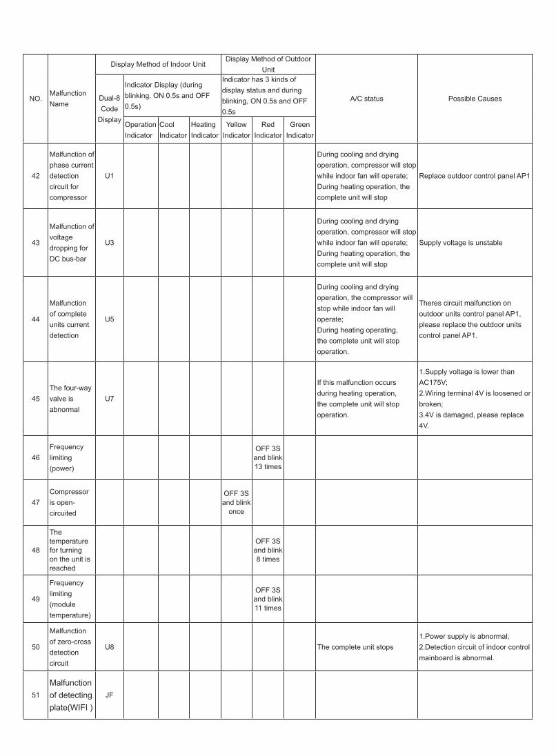
42
Malfunction of phase currentdetection circuit for compressor
U1
During cooling and dryingoperation, compressor will stopwhile indoor fan will operate;During heating operation, thecomplete unit will stop
Replace outdoor control panel AP1
43
Malfunction of voltagedropping forDC bus-bar
U3
During cooling and dryingoperation, compressor will stopwhile indoor fan will operate;During heating operation, thecomplete unit will stop
Supply voltage is unstable
44
Malfunction of complete units current detection
U5
During cooling and dryingoperation, the compressor willstop while indoor fan will operate; During heating operating, the complete unit will stop operation.
Theres circuit malfunction on outdoor units control panel AP1, please replace the outdoor units control panel AP1.
45The four-wayvalve isabnormal
U7
If this malfunction occurs during heating operation, the complete unit will stop operation.
1.Supply voltage is lower than AC175V;2.Wiring terminal 4V is loosened or broken;3.4V is damaged, please replace 4V.
46Frequency limiting (power)
OFF 3Sand blink13 times
47Compressor is open-circuited
OFF 3Sand blink
once
48
The temperature for turning on the unit is reached
OFF 3Sand blink8 times
49
Frequency limiting (module temperature)
OFF 3Sand blink11 times
50
Malfunction of zero-cross detection circuit
U8 The complete unit stops1.Power supply is abnormal;2.Detection circuit of indoor control mainboard is abnormal.
51
Malfunctionof detectingplate(WIFI )
JF
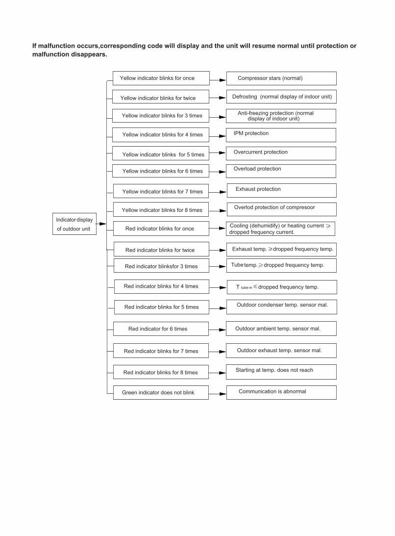
If malfunction occurs,corresponding code will display and the unit will resume normal until protection ormalfunction disappears.
Analysis or processing of some of the malfunction display:1. Compressor discharge protectionPossible causes: shortage of refrigerant; blockage of air filter; poor ventilation or air flow short pass for condenser; the system has noncondensing gas (such as air, water etc.); blockage of capillary assy (including filter); leakage inside four-way valve causes incorrect operation; malfunction of compressor; malfunction of protection relay; malfunction of discharge sensor; outdoor temperature too high. Processing method: refer to the malfunction analysis in the above section.2. Low voltage overcurrent protectionPossible cause: Sudden drop of supply voltage.3. Communication malfunctionProcessing method: Check if communication signal cable is connected reliably.4. Sensor open or short circuitProcessing method: Check whether sensor is normal, connected with the corre sponding position on the controller and if damage of lead wire is found.5. Compressor over load protectionPossible causes: insufficient or too much refrigrant; blockage of capillary and increase of suction temp.; improper running of compressor, burning in or stuck of bearing, damage of discharge valve; malfunction of protector.Processing method: adjust refrigerant amount; replace the capillary; replace the compressor; use universal meter to check if the contactor of compress or is fine when it is not overheated, if not replace the protector.6. System malfunctioni.e.overload protection.When tube temperature(Check the temperature of outdoor heat exchanger when cooling and check the temperatur e of indoor heat exchanger when heating) is too high, protection will be activated.Possible causes: Outdoor temperature is too high when cooling; insufficient outdoor air circulation; refrigerant flow malfunction.please refer to the malfunction analysis in the previous section for handling method .7. IPM module protectionProcessing method:Once the module malfunction happens,if it persists for a long time and can not be selfcanceled, cut off the power and turn off the unit,and then re-energize the unit again after about 10 min.After repeating the procedure for sever times, if the malfunction still exists,replace the module.
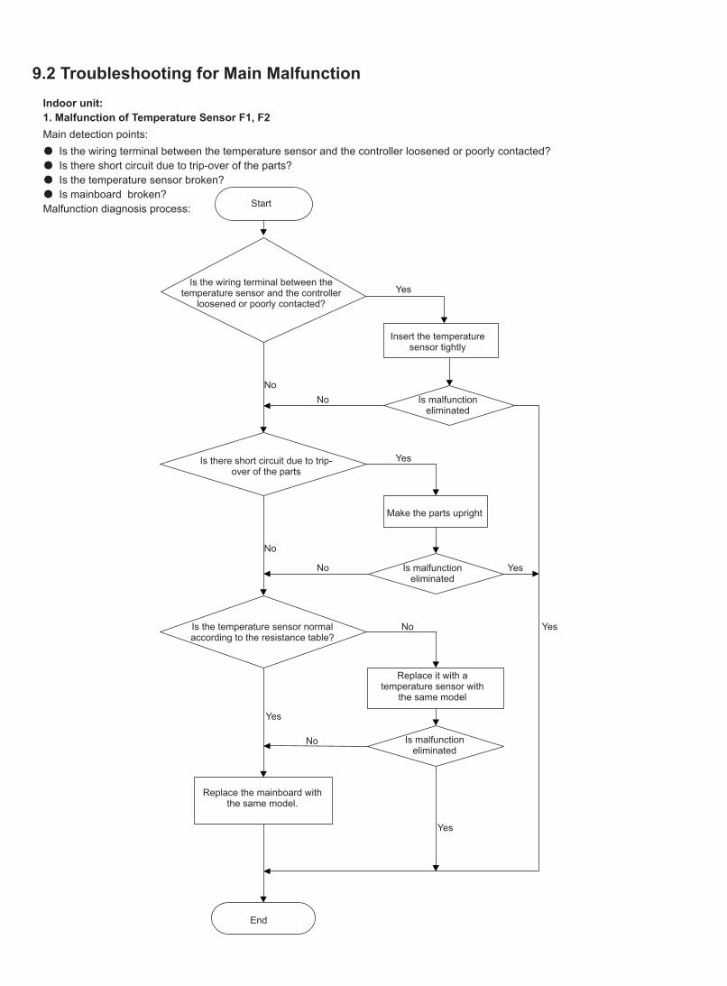
9.2 Troubleshooting for Main MalfunctionIndoor unit:1. Malfunction of Temperature Sensor F1, F2Main detection points:● Is the wiring terminal between the temperature sensor and the controller loosened or poorly contacted?● Is there short circuit due to trip-over of the parts?● Is the temperature sensor broken?● Is mainboard broken?Malfunction diagnosis process:
Is the wiring terminal between the temperature sensor and the controller
loosened or poorly contacted?
Start
Insert the temperature sensor tightly
Yes
Yes
Yes
Yes
Yes
Yes
No
No
No
No
No
No
Is malfunction eliminated
Is malfunction eliminated
Is malfunction eliminated
Replace it with a temperature sensor with
the same model
Make the parts upright
Is there short circuit due to trip-over of the parts
Is the temperature sensor normal according to the resistance table?
Replace the mainboard with the same model.
End
2. Malfunction of Blocked Protection of IDU Fan Motor H6Main detection points:● Is the control terminal of PG motor connected tightly?● Is the feedback interface of PG motor connected tightly?● The fan motor cant operate ?● The motor is broken?● Detectioncircuit of the mainboard is defined abnormal?Malfunction diagnosis process:
Start
While power is off stir the blade with a tool to see whether the
blade rotates smoothly
Check if the connection of PG motor feedback terminal is firm
Check if the connection of PG motor control terminal is firm
Turn on the unit again; measure whether the output voltage on
control terminal for PG motor is more than 50V within 1 min after
the louvers are opened
Tighten the screw; reassemble the blade, motor and shaft bearing rubber base sub-assy to make
sure there is no foreign object between themYes
Yes
Yes
Yes
Yes
Yes
Yes
Yes
Yes
Yes
No
No
No
No
No
No
No
No
No
Is malfunction eliminated
Is malfunction eliminated
Is malfunction eliminated
Is malfunction eliminated
Is the motor started up
Replace PG motor
Replace the mainboard with the same model
Measure the voltage of this foot to neutral wire on the mainboard
End
Reinstall the blade and motor correctly
Insert the control terminal of PG motor tightly
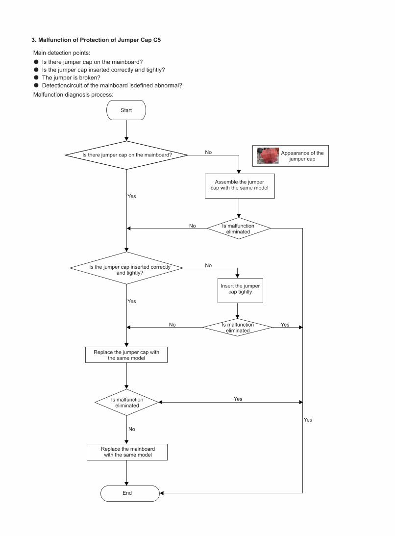
3. Malfunction of Protection of Jumper Cap C5
Main detection points:● Is there jumper cap on the mainboard?● Is the jumper cap inserted correctly and tightly?● The jumper is broken?● Detectioncircuit of the mainboard isdefined abnormal?Malfunction diagnosis process:
Start
Is there jumper cap on the mainboard?
Is the jumper cap inserted correctly and tightly?
Replace the jumper cap with the same model
Appearance of the jumper cap
Assemble the jumpercap with the same model
Insert the jumper cap tightly
Is malfunction eliminated
Is malfunction eliminated
Is malfunction eliminated
Replace the mainboardwith the same model
End
Yes
Yes
Yes
Yes
Yes
No
No
No
No
No
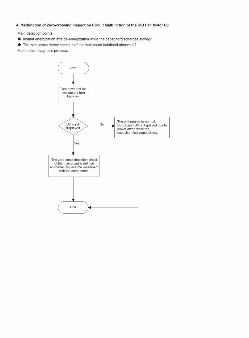
4. Malfunction of Zero-crossing Inspection Circuit Malfunction of the IDU Fan Motor U8
Main detection points:● Instant energization afte de-energization while the capacitordischarges slowly?● The zero-cross detectioncircuit of the mainboard isdefined abnormal?Malfunction diagnosis process:
Turn power off for 1minute,the turn
back on
The unit returns to normal. Conclusion:U8 is displayed due to power off/on while thecapacitor discharges slowly.
U8 is still displayed
The zero-cross detection circuit of the mainboard is defined
abnormal.Replace the mainboard with the same model
Yes
No
Start
End
Start
Is malfunction eliminated
The end
check if the connection wire are correctly connected
Replace the detecting plate with the same model
Replace the mainboard with the same model
Yes
Yes
No
5.Malfunction of detecting plate(WIFI) JF
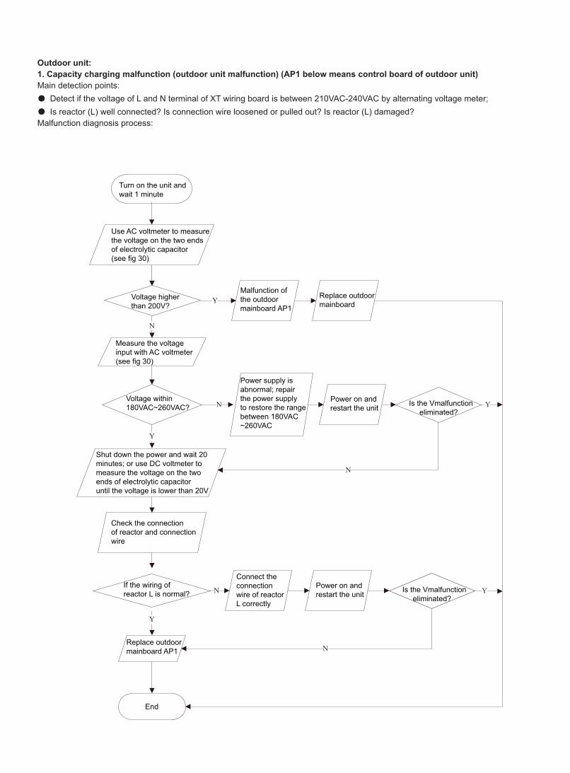
Outdoor unit:1. Capacity charging malfunction (outdoor unit malfunction) (AP1 below means control board of outdoor unit)Main detection points:● Detect if the voltage of L and N terminal of XT wiring board is between 210VAC-240VAC by alternating voltage meter;● Is reactor (L) well connected? Is connection wire loosened or pulled out? Is reactor (L) damaged?Malfunction diagnosis process:
N
Y
N
Y
N
Y
N
Y
N
Y
Turn on the unit and wait 1 minute
Use AC voltmeter to measure the voltage on the two ends of electrolytic capacitor (see fig 30)
Voltage higher than 200V?
Malfunction of the outdoor mainboard AP1
Replace outdoor mainboard
Measure the voltage input with AC voltmeter(see fig 30)
Voltage within 180VAC~260VAC?
Shut down the power and wait 20 minutes; or use DC voltmeter to measure the voltage on the two ends of electrolytic capacitor until the voltage is lower than 20V
Check the connection of reactor and connection wire
If the wiring of reactor L is normal?
Replace outdoor mainboard AP1
End
Power supply is abnormal; repair the power supply to restore the range between 180VAC~260VAC
Power on and restart the unit Is the Vmalfunction
eliminated?
Is the Vmalfunction eliminated?
Connect the connection wire of reactor L correctly
Power on and restart the unit
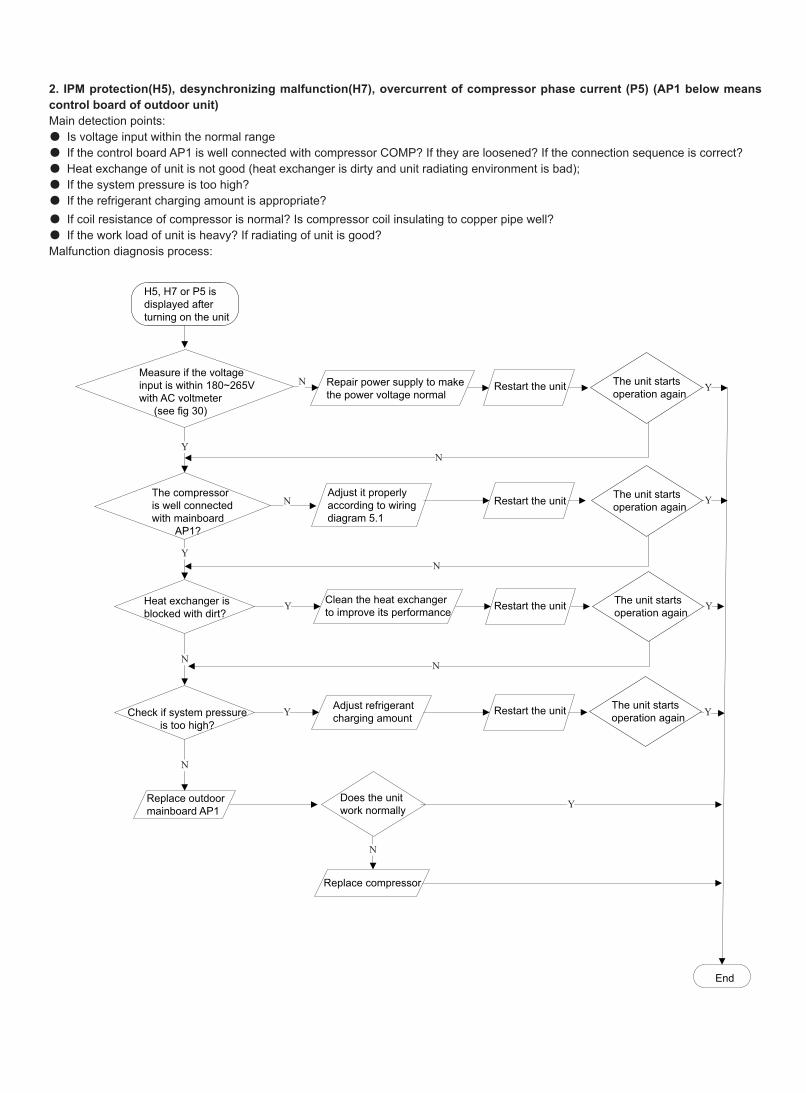
2. IPM protection(H5), desynchronizing malfunction(H7), overcurrent of compressor phase current (P5) (AP1 below means control board of outdoor unit)Main detection points:● Is voltage input within the normal range● If the control board AP1 is well connected with compressor COMP? If they are loosened? If the connection sequence is correct?● Heat exchange of unit is not good (heat exchanger is dirty and unit radiating environment is bad);● If the system pressure is too high?● If the refrigerant charging amount is appropriate?● If coil resistance of compressor is normal? Is compressor coil insulating to copper pipe well?● If the work load of unit is heavy? If radiating of unit is good?Malfunction diagnosis process:
N
N
YN
Y
Y
Y
N
NN
N
N
Y
Y
Y
Y
Y
H5, H7 or P5 is displayed after turning on the unit
Measure if the voltage input is within 180~265V with AC voltmeter (see fig 30)
The compressor is well connectedwith mainboard AP1?
Heat exchanger is blocked with dirt?
Clean the heat exchanger to improve its performance
Restart the unit
Restart the unit
Restart the unit
Restart the unit
The unit starts operation again
The unit starts operation again
The unit starts operation again
The unit starts operation again
Repair power supply to make the power voltage normal
Check if system pressure is too high?
Adjust refrigerant charging amount
Replace outdoor mainboard AP1
Replace compressor
Does the unit work normally
End
Adjust it properly according to wiring diagram 5.1
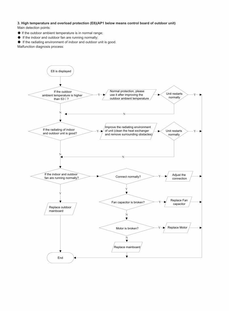
3. High temperature and overload protection (E8)(AP1 below means control board of outdoor unit)Main detection points:● If the outdoor ambient temperature is in normal range;● If the indoor and outdoor fan are running normally;● If the radiating environment of indoor and outdoor unit is good.Malfunction diagnosis process:
Y
N
Y
Y
N
N
Y
Y
Y
Y
Y
Y
N
N
N
E8 is displayed
If the outdoor ambient temperature is higher than 53℃?
Normal protection, please use it after improving the outdoor ambient temperature
Unit restarts normally
Unit restarts normally
If the radiating of indoor and outdoor unit is good?
Improve the radiating environment of unit (clean the heat exchanger and remove surrounding obstacles)
If the indoor and outdoor fan are running normally? Connect normally? Adjust the
connection
Replace outdoor mainboard
Replace mainboard
Replace Motor
Replace Fan capacitorFan capacitor is broken?
Motor is broken?
End
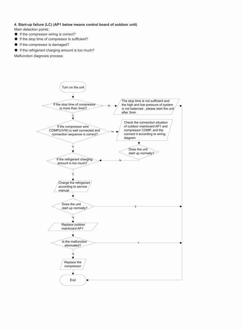
4. Start-up failure (LC) (AP1 below means control board of outdoor unit)Main detection points:● If the compressor wiring is correct?● If the stop time of compressor is sufficient?● If the compressor is damaged?● If the refrigerant charging amount is too much?Malfunction diagnosis process:
If the stop time of compressor is more than 3min?
The stop time is not sufficient and the high and low pressure of system is not balanced , please start the unit after 3min
If the compressor wire COMP(UVW) is well connected and connection sequence is correct?
Check the connection situation of outdoor mainboard AP1 and compressor COMP, and the connect it according to wiring diagram
If the refrigerant charging amount is too much?
Does the unit start up normally?
Charge the refrigerant according to service manual
Does the unit start up normally?
Replace outdoor mainboard AP1
Is the malfunction eliminated?
Replace the compressor
End
Turn on the unit
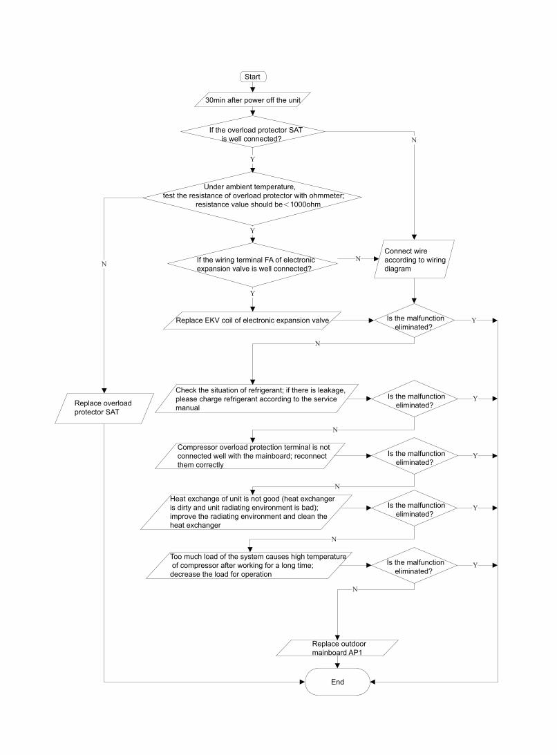
5. Overload and high discharge temperature malfunctionMain detection points:● If the electronic expansion valve is connected well? Is the electronic expansion valve damaged?● If the refrigerant is leaked?● The compressor overload protection terminal is not connected well with the mainboard?● If the overload protector is damaged?● Heat exchange of unit is not good? (heat exchanger is dirty and unit radiating environment is bad)● Too much load of the system causes high temperature of compressor after working for a long time?● Malfunction of discharge temperature sensor?Malfunction diagnosis process:
Y
N
N
Y
Y
N
N
N
N
N
Y
Y
Y
N
Y
Y
Start
30min after power off the unit
If the overload protector SAT is well connected?
Under ambient temperature, test the resistance of overload protector with ohmmeter; resistance value should be<1000ohm
If the wiring terminal FA of electronic expansion valve is well connected?
Replace EKV coil of electronic expansion valve
Check the situation of refrigerant; if there is leakage, please charge refrigerant according to the service manual
Compressor overload protection terminal is not connected well with the mainboard; reconnect them correctly
Heat exchange of unit is not good (heat exchanger is dirty and unit radiating environment is bad);improve the radiating environment and clean the heat exchanger
Too much load of the system causes high temperature of compressor after working for a long time; decrease the load for operation
Is the malfunction eliminated?
Is the malfunction eliminated?
Is the malfunction eliminated?
Is the malfunction eliminated?
Is the malfunction eliminated?
Replace outdoor mainboard AP1
End
Replace overload protector SAT
Connect wire according to wiring diagram
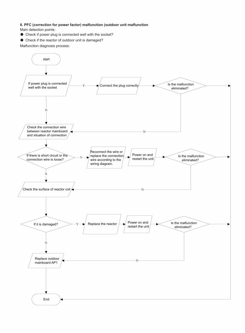
6. PFC (correction for power factor) malfunction (outdoor unit malfunctionMain detection points:● Check if power plug is connected well with the socket?● Check if the reactor of outdoor unit is damaged?Malfunction diagnosis process:
(11) PFC (correction for power factor) malfunction (outdoor unit malfunction)Main detection points:
Check if power plug is connected well with the socketCheck if the reactor of outdoor unit is damaged?
Malfunction diagnosis process:
Y
Y
N
N
N
N
Y
N
N
start
If power plug is connected well with the socket Connect the plug correctly
Check the connection wire between reactor mainboard and situation of connection
If there is short circuit or the connection wire is loose?
Reconnect the wire or replace the connection wire according to the wiring diagram.
Check the surface of reactor coil
If it is damaged? Replace the reactor Power on and restart the unit
Power on and restart the unit
Replace outdoor mainboard AP1
End
Is the malfunction eliminated?
Is the malfunction eliminated?
Is the malfunction eliminated?
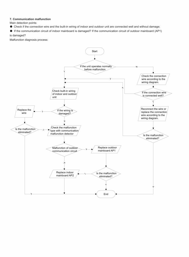
7. Communication malfunctionMain detection points:● Check if the connection wire and the built-in wiring of indoor and outdoor unit are connected well and without damage;● If the communication circuit of indoor mainboard is damaged? If the communication circuit of outdoor mainboard (AP1) is damaged?Malfunction diagnosis process:
(12) Communication malfunctionMain detection points:
Check if the connection wire and the built-in wiring of indoor and outdoor unit are connected well and without damage;If the communication circuit of indoor mainboard is damaged? If the communication circuit of outdoor mainboard (AP1) is damaged?
Malfunction diagnosis process:
Start
If the unit operates normally before malfunction
Check built-in wiring of indoor and outdoor unit
If the wiring is damaged?
Replace the wire
Check the malfunction type with communication malfunction detector
Malfunction of outdoor communication circuit
Replace outdoor mainboard AP1
Replace indoor mainboard AP2
Is the malfunction eliminated?
Is the malfunction eliminated?
End
Check the connection wire according to the wiring diagram.
Reconnect the wire or replace the connection wire according to the wiring diagram.
Is the malfunction eliminated?
If the connection wire is connected well?
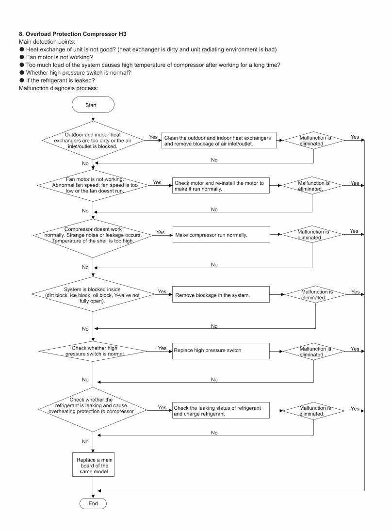
8. Overload Protection Compressor H3Main detection points:● Heat exchange of unit is not good? (heat exchanger is dirty and unit radiating environment is bad)● Fan motor is not working?● Too much load of the system causes high temperature of compressor after working for a long time?● Whether high pressure switch is normal?● If the refrigerant is leaked?Malfunction diagnosis process:
Start
Outdoor and indoor heatexchangers are too dirty or the air
inlet/outlet is blocked.Clean the outdoor and indoor heat exchangers and remove blockage of air inlet/outlet.
Malfunction iseliminated.
Malfunction iseliminated.
Malfunction iseliminated.
Malfunction iseliminated.
Malfunction iseliminated.
Malfunction iseliminated.
Check motor and re-install the motor to make it run normally.
Make compressor run normally.
Remove blockage in the system.
Replace high pressure switch
Check the leaking status of refrigerantand charge refrigerant
Fan motor is not working.Abnormal fan speed; fan speed is too
low or the fan doesnt run.
Compressor doesnt worknormally. Strange noise or leakage occurs.
Temperature of the shell is too high.
System is blocked inside(dirt block, ice block, oil block, Y-valve not
fully open).
Check whether highpressure switch is normal
Check whether therefrigerant is leaking and cause
overheating protection to compressor
Replace a main board of the same model.
End
Yes Yes
Yes
Yes
Yes
Yes
Yes
Yes
Yes
Yes
Yes
Yes
NoNo
No
No
No
No
No
No
No
No
No
No
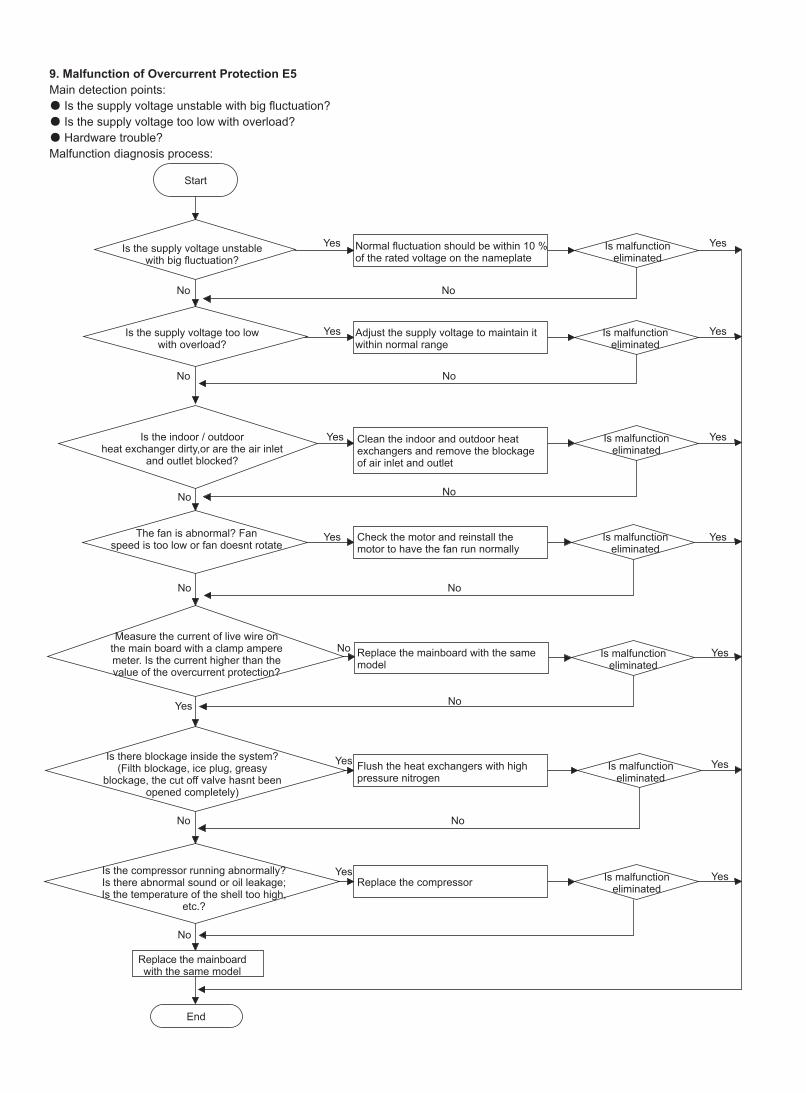
9. Malfunction of Overcurrent Protection E5Main detection points:● Is the supply voltage unstable with big fluctuation?● Is the supply voltage too low with overload?● Hardware trouble?Malfunction diagnosis process:
Start
Is the supply voltage unstablewith big fluctuation?
Normal fluctuation should be within 10 % of the rated voltage on the nameplate
Adjust the supply voltage to maintain it within normal range
Clean the indoor and outdoor heat exchangers and remove the blockage of air inlet and outlet
Check the motor and reinstall the motor to have the fan run normally
Replace the mainboard with the same model
Flush the heat exchangers with high pressure nitrogen
Replace the compressor
Replace the mainboard with the same model
End
Is the supply voltage too lowwith overload?
Is the indoor / outdoorheat exchanger dirty,or are the air inlet
and outlet blocked?
The fan is abnormal? Fanspeed is too low or fan doesnt rotate
Measure the current of live wire on the main board with a clamp ampere meter. Is the current higher than the value of the overcurrent protection?
Is there blockage inside the system? (Filth blockage, ice plug, greasy
blockage, the cut off valve hasnt been opened completely)
Is the compressor running abnormally? Is there abnormal sound or oil leakage; Is the temperature of the shell too high,
etc.?
Is malfunction eliminated
Is malfunction eliminated
Is malfunction eliminated
Is malfunction eliminated
Is malfunction eliminated
Is malfunction eliminated
Is malfunction eliminated
Yes Yes
Yes
Yes
Yes
Yes
Yes
Yes
Yes
Yes
Yes
Yes
Yes
Yes
No No
No
No
No
No
No No
No
No
No
No
No
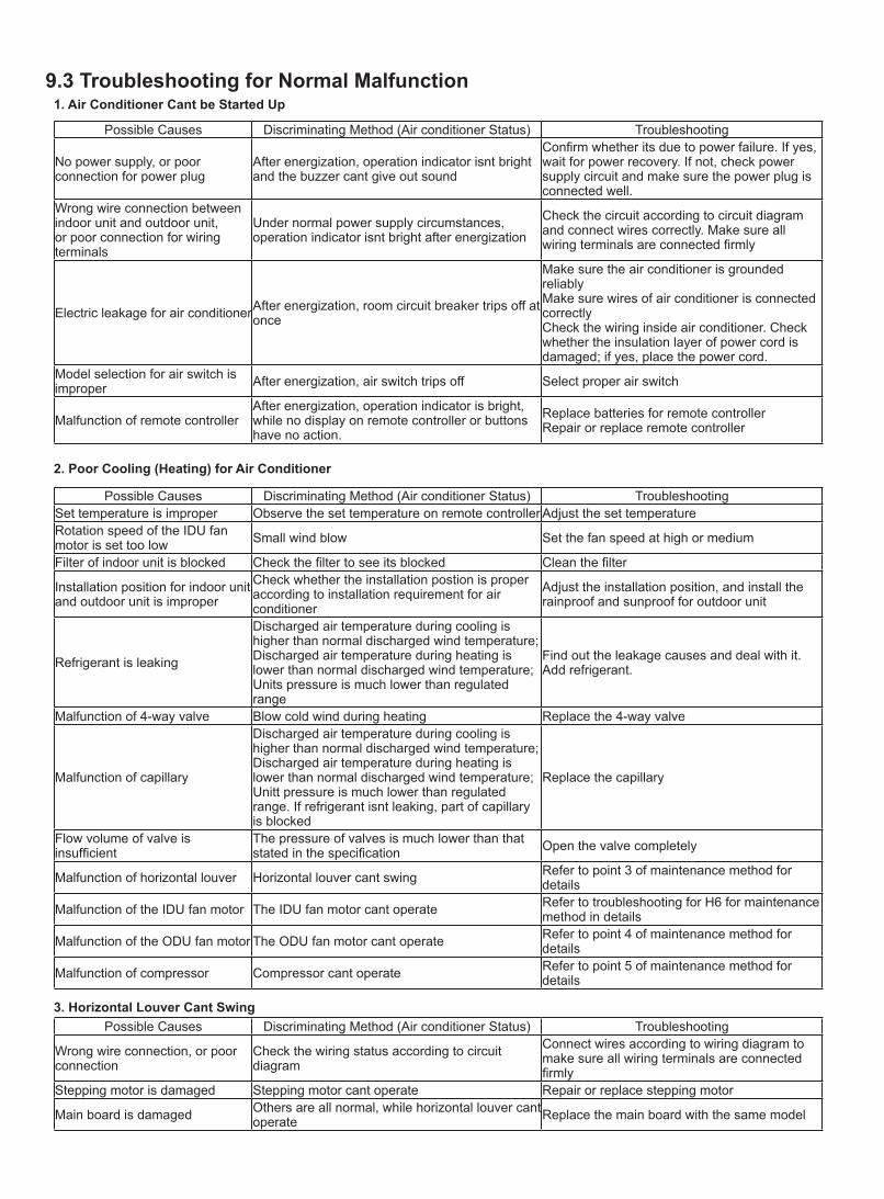
Possible Causes Discriminating Method (Air conditioner Status) Troubleshooting Set temperature is improper Observe the set temperature on remote controller Adjust the set temperatureRotation speed of the IDU fan motor is set too low Small wind blow Set the fan speed at high or medium
Filter of indoor unit is blocked Check the filter to see its blocked Clean the filter
Installation position for indoor unit and outdoor unit is improper
Check whether the installation postion is proper according to installation requirement for air conditioner
Adjust the installation position, and install the rainproof and sunproof for outdoor unit
Refrigerant is leaking
Discharged air temperature during cooling is higher than normal discharged wind temperature; Discharged air temperature during heating is lower than normal discharged wind temperature; Units pressure is much lower than regulated range
Find out the leakage causes and deal with it. Add refrigerant.
Malfunction of 4-way valve Blow cold wind during heating Replace the 4-way valve
Malfunction of capillary
Discharged air temperature during cooling is higher than normal discharged wind temperature; Discharged air temperature during heating is lower than normal discharged wind temperature; Unitt pressure is much lower than regulated range. If refrigerant isnt leaking, part of capillary is blocked
Replace the capillary
Flow volume of valve is insufficient
The pressure of valves is much lower than that stated in the specification Open the valve completely
Malfunction of horizontal louver Horizontal louver cant swing Refer to point 3 of maintenance method for details
Malfunction of the IDU fan motor The IDU fan motor cant operate Refer to troubleshooting for H6 for maintenance method in details
Malfunction of the ODU fan motor The ODU fan motor cant operate Refer to point 4 of maintenance method for details
Malfunction of compressor Compressor cant operate Refer to point 5 of maintenance method for details
9.3 Troubleshooting for Normal Malfunction1. Air Conditioner Cant be Started Up
2. Poor Cooling (Heating) for Air Conditioner
3. Horizontal Louver Cant Swing
Possible Causes Discriminating Method (Air conditioner Status) Troubleshooting
No power supply, or poor connection for power plug
After energization, operation indicator isnt bright and the buzzer cant give out sound
Confirm whether its due to power failure. If yes, wait for power recovery. If not, check power supply circuit and make sure the power plug is connected well.
Wrong wire connection between indoor unit and outdoor unit, or poor connection for wiring terminals
Under normal power supply circumstances, operation indicator isnt bright after energization
Check the circuit according to circuit diagram and connect wires correctly. Make sure all wiring terminals are connected firmly
Electric leakage for air conditionerAfter energization, room circuit breaker trips off at once
Make sure the air conditioner is grounded reliablyMake sure wires of air conditioner is connected correctlyCheck the wiring inside air conditioner. Check whether the insulation layer of power cord is damaged; if yes, place the power cord.
Model selection for air switch is improper After energization, air switch trips off Select proper air switch
Malfunction of remote controller After energization, operation indicator is bright, while no display on remote controller or buttons have no action.
Replace batteries for remote controllerRepair or replace remote controller
Possible Causes Discriminating Method (Air conditioner Status) Troubleshooting
Wrong wire connection, or poor connection
Check the wiring status according to circuit diagram
Connect wires according to wiring diagram to make sure all wiring terminals are connected firmly
Stepping motor is damaged Stepping motor cant operate Repair or replace stepping motor
Main board is damaged Others are all normal, while horizontal louver cant operate Replace the main board with the same model
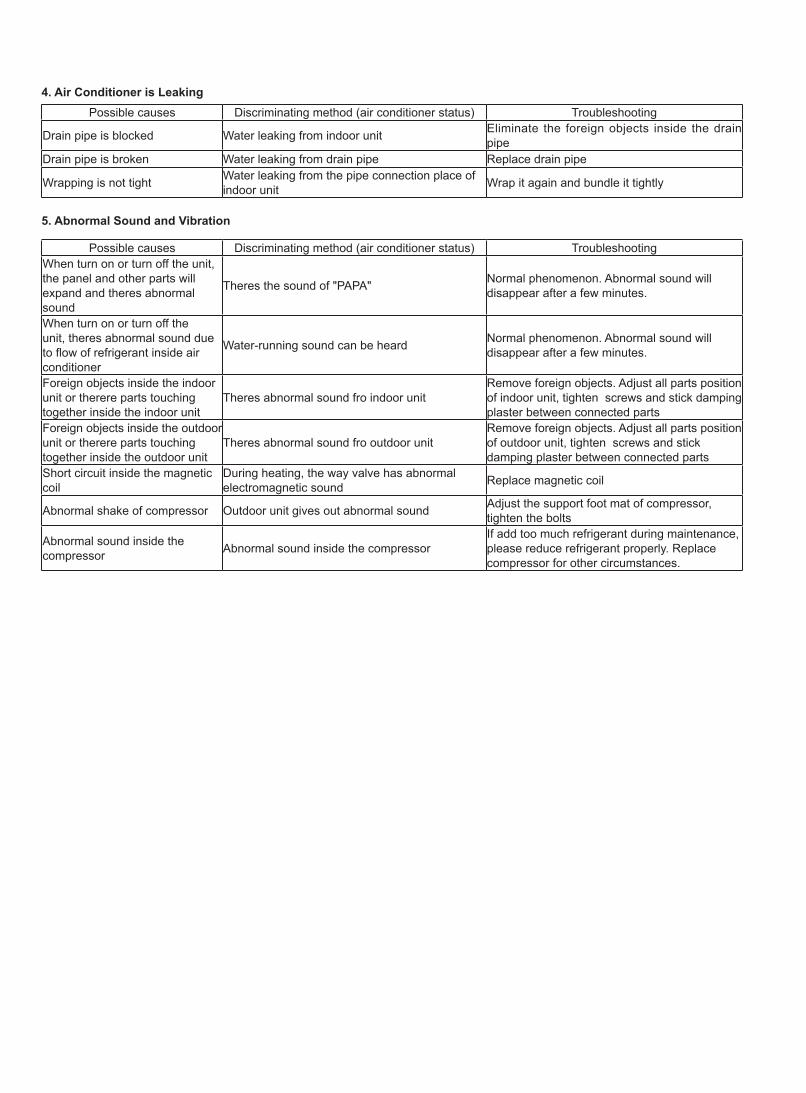
5. Abnormal Sound and Vibration
Possible causes Discriminating method (air conditioner status) Troubleshooting When turn on or turn off the unit, the panel and other parts will expand and theres abnormal sound
Theres the sound of "PAPA" Normal phenomenon. Abnormal sound will disappear after a few minutes.
When turn on or turn off the unit, theres abnormal sound due to flow of refrigerant inside air conditioner
Water-running sound can be heard Normal phenomenon. Abnormal sound will disappear after a few minutes.
Foreign objects inside the indoor unit or therere parts touching together inside the indoor unit
Theres abnormal sound fro indoor unitRemove foreign objects. Adjust all parts position of indoor unit, tighten screws and stick damping plaster between connected parts
Foreign objects inside the outdoor unit or therere parts touching together inside the outdoor unit
Theres abnormal sound fro outdoor unitRemove foreign objects. Adjust all parts position of outdoor unit, tighten screws and stick damping plaster between connected parts
Short circuit inside the magnetic coil
During heating, the way valve has abnormal electromagnetic sound Replace magnetic coil
Abnormal shake of compressor Outdoor unit gives out abnormal sound Adjust the support foot mat of compressor, tighten the bolts
Abnormal sound inside the compressor Abnormal sound inside the compressor
If add too much refrigerant during maintenance, please reduce refrigerant properly. Replace compressor for other circumstances.
4. Air Conditioner is Leaking Possible causes Discriminating method (air conditioner status) Troubleshooting
Drain pipe is blocked Water leaking from indoor unit Eliminate the foreign objects inside the drain pipe
Drain pipe is broken Water leaking from drain pipe Replace drain pipe
Wrapping is not tight Water leaking from the pipe connection place of indoor unit Wrap it again and bundle it tightly
Designed by Cooper&Hunter International Corporation, Oregon, USAwww.cooperandhunter.com


![Midea HK( Midea Air ) aa Air o Air 03 . Aurora ] Split Type Inverter Air—Conditioner ( Cooling ) wi9 Split Type Inverter Air-Conditioner ( Heating ) 3} ENERGY LABEL (Inverter) E-COtäit](https://static.documents.pub/doc/80x56/5fdb3873aa22060bcb5bb018/midea-hk-midea-air-aa-air-o-air-03-aurora-split-type-inverter-airaconditioner.jpg)


