1524 IEEE ANTENNAS AND WIRELESS PROPAGATION LETTERS, VOL. 10, 2011
Split-Ring Resonator Loading for the SlottedWaveguide Antenna Stiffened StructureKelvin J. Nicholson, Wayne S. T. Rowe, Paul J. Callus, and Kamran Ghorbani
Abstract—Slotted waveguide antenna stiffened structure(SWASS) utilizes hat-stiffeners on thin skins or blade stiffenersin sandwich structures as microwave waveguides. By machiningslots through the outer skin and into the waveguide, large slottedwaveguide antenna arrays may be integrated into a load-bearingstructure. However, the slot length is typically resonant withhalf-wavelength spacing, thereby degrading the load-bearing ca-pacity of the structure. This letter demonstrates a simple methodto achieve comparable gain from a slot radiator with subresonantlength by means of a single split ring. The adverse structuralimpact of the individual slot and the slot array may therefore bereduced.
S LOTTED waveguide antennas (SWAs) date back to the1940s [1] and are still in popular use today. Their mechan-
ical robustness and simple construction favor a variety of appli-cations across the maritime and aerospace industries. Althoughaluminum and brass are perhaps the most common media forSWA, such materials are unsuited to large-scale arrays wherethermal expansion and mechanical rigidity may necessitate theuse of significant structural reinforcing. Alternatively, metal-lized carbon fiber reinforced polymer (CFRP) has been used forthe fabrication of space-based SWA [2] to achieve a significantweight saving with the required dimensional stability.The increasing use of CFRP in modern aircraft has inspired
the slotted waveguide antenna stiffened structure (SWASS) con-cept [3], [4] illustrated in Fig. 1. The dimensions of the stiffenercross section in conventional hat-stiffened skins or the skin-to-skin separation in sandwich panels, is comparable to the wave-guide dimensions in common military applications. Slots ma-chined through the outer skin of the stiffened panel and intothe waveguide may operate as SWA arrays. The SWASS con-cept may therefore be integrated into the airframe with verylittle weight and drag penalty compared to conventional pro-truding aircraft antennas. However, the structural impact of the
Manuscript received September 14, 2011; revised December 06, 2011; ac-cepted December 19, 2011. Date of publication December 22, 2011; date of cur-rent version January 30, 2012. This work was conducted within the DefenceMa-terials Technology Centre, which was established and is supported by the Aus-tralian Government’s Defence Future Capability Technology Centre (DFCTC)initiative.K. J. Nicholson and P. J. Callus are with the Defence Science and
Technology Organisation, Melbourne, Victoria 3207, Australia (e-mail:[email protected]).W. S. T. Rowe andK. Ghorbani are with the School of Electrical Engineering,
RMIT University, Melbourne, Victoria 3001, Australia.Color versions of one or more of the figures in this letter are available online
at http://ieeexplore.ieee.org.Digital Object Identifier 10.1109/LAWP.2011.2181474
Fig. 1. SWASS concept. Hat-stiffeners on thin skins and blades in sandwichpanels can support both structural load and SWA arrays.
slot is a significant concern for SWASS applications [5]. Hence,a means to reduce the slot length is desired in order to minimizethe impact of the slot array on the mechanical properties of theSWASS.This letter presents a simple method, employing a single split-
ring resonator (SRR), to couple energy through the slot in aSWA. This technique allows for a significant reduction in slotlength, thereby alleviating some of the adverse structural im-pacts of the slot size on the strength of the SWASS without se-verely compromising the electromagnetic performance of thearray.
II. RESONANT SLOT DESIGN OVERVIEW
The theory and design of a conventional resonant SWA iswell documented elsewhere [6], [7]. In brief, for the funda-mental mode in a rectangular waveguide, a longitudinal slot inthe broadwall is approximated by a shunt admittance
(1)
where is the admittance of the empty waveguide. The reso-nant slot length for a given frequency, wall thickness, and offsetfrom the waveguide centerline is determined when the admit-tance is a pure conductance. For this investigation, WR-137copper waveguide with a wall thickness of 1.00 mm was used.The slot offset from the broadwall centerline was set to 8.70 mm(25% of the broadwall dimension), and the slot width was fixedat 2.60 mm. The slot ends were rounded (with 1.30-mm radius)to simplify manufacture.The normalized admittance of a single slot was determined
using the commercial electromagnetic simulation softwareMicrowave Studio by Computer Simulation Technology (CST)and the design cell described in [8]. For the specified di-mensions, a resonant slot length of 22.85 mm (0.495 )was determined for operation at 6.50 GHz (where is thefree-space wavelength).To construct a conventional resonant SWA array at 6.50 GHz,
the centers of the 22.85-mm (0.495 )-long slots are spaced
30.76 mm (0.5 ) apart on alternate sides of the broadwallcenterline (where is the guided wavelength). The separationbetween slot ends is subsequently less than the resonant slotlength. The close proximity of slots in the array will severelydegrade the mechanical properties of the SWASS as reportedin [5].To recover the mechanical properties of the SWASS, it is de-
sirable to maximize the separation between the slot ends bymin-imizing the slot length. For example, in [9], it was shown thatmechanical slot-to-slot interaction ceases, and the failure loadof the component is equivalent to that of the slots in isolation,when the slot spacing exceeds four times the characteristic slotdimension. For the SWA array to support a structural load, assuggested by the SWASS concept, it is desirable to approach orexceed this ratio.For this investigation, the radiation characteristics of a single
slot in the broadwall of a waveguide were considered. The ob-jective is to achieve comparable realized gain from a single slotwith length less than 22.85 mm.
III. SRR-LOADED SUBRESONANT LENGTH SLOT
The poor transmission of electromagnetic energy through asubresonant aperture in an infinite metallic sheet is a classicalproblem that was first addressed by Bethe [10]. It remaineda technical challenge until Ebbesen’s group experimentallydemonstrated that a single subresonant aperture surroundedby a periodic corrugation may achieve significant transmis-sion enhancement [11]. The theoretical analysis of Oliner andJackson later established the role of surface plasmon polaritonsin achieving this enhanced transmission [12], [13]. The recentdevelopment of metamaterials has since inspired an alternativetheoretical solution to the problem [14]. However, the practicalissues regarding the fabrication of a suitable metamaterial withsufficient dimensions and precision were discussed in [15],where an alternative resonant approach to the transmissionenhancement problem was presented.This resonant approach to enhance the transmission em-
ployed a metamaterial layer constructed from an array of SRRs.In [15], it was demonstrated how such a metamaterial layer,fabricated with transverse dimensions similar to the aperturesize, may significantly enhance the transmitted power. Further-more, enhanced transmission was observed for the single-SRRcase. Theoretical and experimental work on this mechanismfor enhanced transmission through a subresonant aperture in aninfinite metallic screen has since been reported in [16] and [17],with the possibility to tune the enhancement frequency reportedin [18].This method of achieving enhanced transmission from a sub-
resonant aperture using a single SRR may be applied to theSWASS concept. Unlike previous work [15]–[18] where theSRR-loaded aperture was excited by a plane wave, this letteris concerned with the waveguide excitation necessary to imple-ment an SWA array. The SWASS concept may therefore be real-ized with reduced impact on both mechanical performance andantenna gain. The proposed geometry for the SWA unit cell ispresented in Fig. 2.The SRR captures a portion of the magnetic flux circulating
in the waveguide. The strong localized electric and magnetic
Fig. 2. Cross section of the SRR-loaded slot in (a) -plane and (b) -plane.Waveguide ports are located at either end of the waveguide with excitation inthe positive -direction. The SRR plane is located at the center of the slot alongthe -axis. The SRR is centered beneath the slot in the -axis.
Fig. 3. Simulated -parameters for the SWA unit cell with a 3.0 12.0 mmSRR beneath a 0.35- slot in a WR-137 waveguide as illustrated in Fig. 2. Thedistinct current distributions on the SRR are illustrated for each resonance.
fields induced in the SRR couple to the slot to achieve a signifi-cant improvement in radiated power compared to the unloadedsubresonant length slot.To illustrate this concept, consider a rectangular SRR with
two splits (0.10 mm wide), a mean -dimension of 3.00 mm,and a ring width of 1.00 mm printed on 0.508-mm-thick RogersRT/duroid 5880 substrate. The SRR is orientated in a WR-137waveguide as illustrated in Fig. 2, with the outer edge of theSRR located 0.50 mm beneath the inner waveguide broadwall.The long dimension of the slot was 16.15 mm (0.35 ), and theslot was offset from the waveguide centerline by 8.70 mm. Fora ring -dimension of 12.00 mm, two distinct resonances wereobserved in Fig. 3.The first resonance (at 5.80 GHz) exhibited the characteristic
behavior of a magnetic dipole formed by current circulating be-tween the upper SRR half and waveguide broadwall. The returncurrent flowing on the waveguide broadwall was intercepted bythe slot admittance and is therefore expected to radiate similar tothe conventional SWA. The second resonance (at 7.10 GHz) ex-hibited the characteristic behavior of a magnetic dipole formedby current circulating about the SRR. Although the localizedfields near the slot were amplified, the excited evanescent wavesare expected to decay rapidly (as discussed in [15]), yielding alow total antenna efficiency.By optimizing the -dimension of the SRR, either resonance
may be tuned to 6.50 GHz. Only slot lengths up to 0.45 wereconsidered for the optimization.As evident in Fig. 4, varying the slot length had a strong ef-
fect on the first resonance (denoted SRR-WG). This is expectedbecause the resonant circuit formed by the upper SRR half andwaveguide broadwall includes the slot admittance, which is de-pendent on slot length. However, varying the slot length hadlittle effect on the second resonance (denoted SRR) because itis only weakly coupled to the slot admittance. For each reso-nance type, the simulated total efficiency (computed as the ratio
1526 IEEE ANTENNAS AND WIRELESS PROPAGATION LETTERS, VOL. 10, 2011
Fig. 4. Simulated ring -dimension dependence on the slot length to achieveeither the first (SRR-WG) or second (SRR) resonance at 6.50 GHz.
Fig. 5. Simulated total efficiency for the conventional slot (no SRR) and SRR-loaded slot (SRR-WG and SRR resonance) at 6.50 GHz.
Fig. 6. Simulated realized gain at 6.50 GHz for a conventional (no SRR) res-onant slot and a slot loaded with a single SRR (optimized for either electric ormagnetic resonance).
between total radiated power and source power) of the singleslot is plotted in Fig. 5.It is necessary to compare the total efficiency instead of radi-
ation efficiency in order to highlight the performance enhance-ment of the SRR loading for the SWA unit cell. The SRR-loadedslot (with -dimension optimized for the first resonance) signif-icantly enhanced the total radiated power. For extremely smallslot lengths (less than 0.2 ), the SRR loaded slot (with -di-mension optimized for the second resonance) was simulated tobe the more efficient radiator.The simulated realized gain in the peak radiation direction
for both resonance conditions is presented in Fig. 6. It is neces-sary to compare realized gain (computed relative to the sourcepower) instead of IEEE gain to highlight the performance of theSWA unit cell. The simulated results suggest a SWAwith signif-icantly reduced slot length and SRR loadingmay exhibit compa-rable gain to a conventional SWA with a slot length of 0.495(22.85 mm). Furthermore, the reduced slot length would pro-vide greater mechanical performance of the antenna structurecompared to a conventional SWA array.
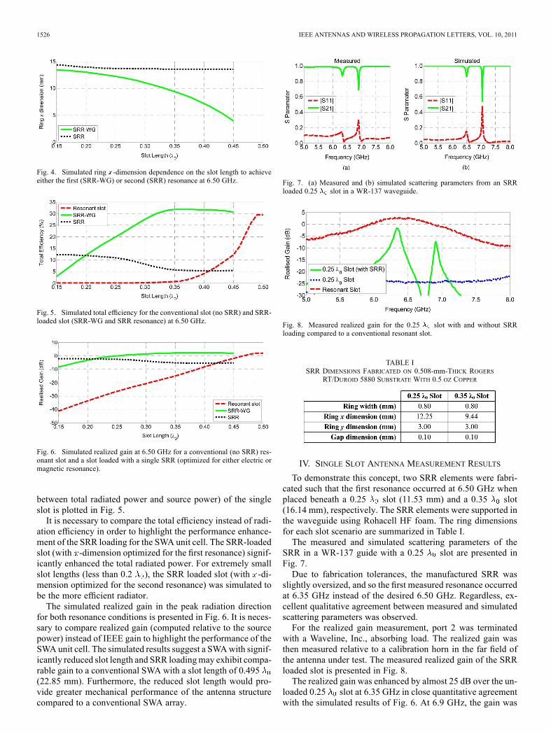
Fig. 7. (a) Measured and (b) simulated scattering parameters from an SRRloaded 0.25 slot in a WR-137 waveguide.
Fig. 8. Measured realized gain for the 0.25 slot with and without SRRloading compared to a conventional resonant slot.
TABLE ISRR DIMENSIONS FABRICATED ON 0.508-mm-THICK ROGERS
RT/DUROID 5880 SUBSTRATE WITH 0.5 OZ COPPER
IV. SINGLE SLOT ANTENNA MEASUREMENT RESULTS
To demonstrate this concept, two SRR elements were fabri-cated such that the first resonance occurred at 6.50 GHz whenplaced beneath a 0.25 slot (11.53 mm) and a 0.35 slot(16.14 mm), respectively. The SRR elements were supported inthe waveguide using Rohacell HF foam. The ring dimensionsfor each slot scenario are summarized in Table I.The measured and simulated scattering parameters of the
SRR in a WR-137 guide with a 0.25 slot are presented inFig. 7.Due to fabrication tolerances, the manufactured SRR was
slightly oversized, and so the first measured resonance occurredat 6.35 GHz instead of the desired 6.50 GHz. Regardless, ex-cellent qualitative agreement between measured and simulatedscattering parameters was observed.For the realized gain measurement, port 2 was terminated
with a Waveline, Inc., absorbing load. The realized gain wasthen measured relative to a calibration horn in the far field ofthe antenna under test. The measured realized gain of the SRRloaded slot is presented in Fig. 8.The realized gain was enhanced by almost 25 dB over the un-
loaded 0.25 slot at 6.35 GHz in close quantitative agreementwith the simulated results of Fig. 6. At 6.9 GHz, the gain was
NICHOLSON et al.: SRR LOADING FOR SWASS 1527
Fig. 9. (a) Measured and (b) simulated scattering parameters from an SRR-loaded 0.35 slot in a WR-137 waveguide.
Fig. 10. Measured realized gain for the 0.35 slot with and without SRRloading compared to a conventional resonant slot.
enhanced by only 17 dB. Neither resonance fully recovered thegain of the conventional (0.495 ) slot.The measured and simulated scattering parameters of the
SRR in a WR-137 waveguide with a 0.35 slot are presentedin Fig. 9.Only a single resonance at 6.50 GHz was observed for this
SRR. The reduced -dimension of the SRR (compared to the0.25 slot case) permitted only the first resonance in the wave-guide band. The reduced inductance of the SRR shifted thesecond resonance above 8 GHz.The measured realized gain of the SRR loaded slot is pre-
sented in Fig. 10. The 0.35 slot with SRR loading almost re-covered the gain of the conventional (0.495 ) resonant slot at6.50 GHz. The reduced bandwidth of the SRR-loaded slot (com-pared to a conventional resonant slot) is inconsequential for theSWASS concept since a conventional SWA array is analogousto a one-dimensional high- resonant structure with a typicalbandwidth of only a few percent. However, for the SWASS con-cept, the reduced slot length ensures greater separation betweensuccessive slot ends in the array and is expected to represent aclear structural benefit over the conventional resonant slot de-sign described in Section II.
V. CONCLUSION
This letter has presented a simple method to achieve accept-able gain from a miniaturized slot by utilizing the strong fieldsinduced in the SRR. The reduced slot length provides a signifi-cant structural advantage necessary for the SWASS concept. A0.35 slot with SRR loading has been shown to recover ap-proximately the same gain (albeit with reduced bandwidth) as
a conventional resonant slot. Furthermore, a 0.25 slot withSRR loading may provide sufficient gain in structure critical im-plementations of the SWASS concept. If the added complexityof an SRR and a small reduction in the peak gain can be toler-ated, then further reduction of the slot length may be possible.The presented method has therefore opened a new design spacewhere the structural performance of the SWA is traded againstthe realized gain of the slot to achieve a truly multifunctionalaircraft structure.
ACKNOWLEDGMENT
The authors acknowledge the Air Force Office of ScientificResearch (AFOSR).
REFERENCES
[1] A. F. Stevenson, “Theory of slots in rectangular wave-guides,” J. Appl.Phys., vol. 19, no. 1, p. 24, 1948.
[2] R. Wagner, “Carbon fibre slotted waveguide arrays,” presented at theMilitary Microw. Conf., Brighton, England, 1986.
[3] P. J. Callus, “Novel concepts for conformal load-bearing antenna struc-ture,” DSTO-TR-2096, 2008.
[4] P. J. Callus, “Conformal load bearing antenna structure for Australiandefence force aircraf,” DSTO-TR-1963, 2007.
[5] J. Sabat, “Structural response of slotted waveguide antenna stiffenedstructure components under compression,” AFIT, WPAFB, OH, 2010.
[6] R. J. Stegen, “Longitudinal shunt slot characteristics,” Hughes AircraftCompany, Culver City, CA, Tech. Memo. No. 261, 1951.
[7] I. P. Kaminow and R. J. Stegen, “Waveguide slot array design,” HughesAircraft Company, Culver City, CA, Tech. Memo. No. 348, 1954.
[8] K.W. Brown, “Design of waveguide slotted arrays using commerciallyavailable finite element analysis software,” in AP-S Dig., 1996, vol. 2,pp. 1000–1003.
[9] C. Soutis, N. A. Fleck, and P. T. Curtis, “Hole-hole interaction incarbon fibre/epoxy laminates under uniaxial compression,” Compos-ites, vol. 22, no. 1, pp. 31–38, Jan. 1991.
[10] H. A. Bethe, “Theory of diffraction by small holes,” Phys. Rev., vol.66, no. 7, p. 163, 1944.
[11] D. E. Grupp, H. J. Leze, T. Thio, and T. W. Ebbesen, “Beyond theBethe limit: Tunable enhanced light transmission through a single sub-wavelength aperture,” Adv. Mater., vol. 11, no. 10, pp. 860–862, 1999.
[12] A. A. Oliner and D. R. Jackson, “Leaky surface-plasmon theory fordramatically enhanced transmission through a subwavelength aperture,Part I: Basic features,” inProc. IEEE Antennas Propag. Soc. Int. Symp.,2003, vol. 2, pp. 1091–1094.
[13] D. R. Jackson, T. Zhao, J. T. Williams, and A. A. Oliner, “Leaky sur-face-plasmon theory for dramatically enhanced transmission through asub-wavelength aperture, Part II: Leaky-wave antennamodel,” inProc.IEEE Antennas Propag. Soc. Int. Symp., 2003, vol. 2, pp. 1095–1098.
[14] A. Alu, F. Bilotti, N. Engheta, and L. Vegni, “How metamaterials maysignificantly affect the wave transmission through a sub-wavelengthhole in a flat perfectly conducting screen,” in Proc. IEE Seminar Meta-mater. Microw. (Sub) Millim. Wave Appl., Photon. Bandgap DoubleNegative Designs, Compon. Experiments, 2003, p. 11.
[15] F. Bilotti, L. Scorrano, E. Ozbay, and L. Vegni, “Enhanced trans-mission through a sub-wavelength aperture: Resonant approachesemploying metamaterials,” J. Opt. A, Pure Appl. Opt., vol. 11, p.114029, 2009.
[16] A. O. Cakmak, K. Aydin, E. Colak, Z. Li, and F. Bilotti, “Enhancedtransmission through a subwavelength aperture using metamaterials,”Appl. Phys. Lett., vol. 95, no. 5, p. 052103, 2009.
[17] K. Aydin, A. O. Cakmak, L. Sahin, Z. Li, F. Bilotti, L. Vegni, and E.Ozbay, “Split-ring-resonator-coupled enhanced transmission througha single subwavelength aperture,” Phys. Rev. Lett., vol. 102, no. 1, p.013904, Jan. 2009.
[18] C. Huang, Z. Zhao, and X. Luo, “Tuning enhanced transmissionfrequency through a subwavelength aperture with active split ringresonator,” presented at the 5th Int. Symp. Adv. Opt. Manuf. TestingTechnol., Smart Struct. Mater. Manuf. Testing, Dalian, China, 2010,765902.