60
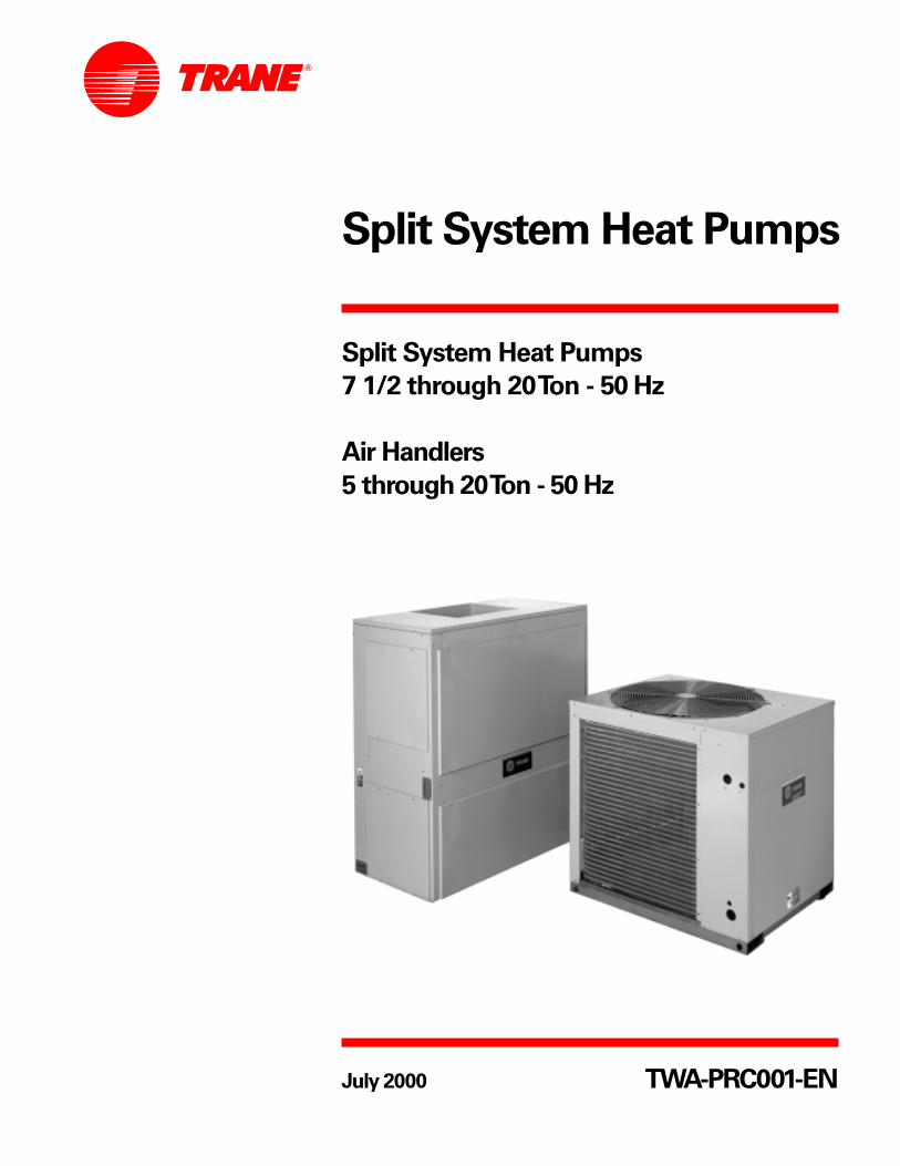
Split System Heat Pumps Split System Heat Pumps 7 1/2 through 20 Ton - 50 Hz Air Handlers 5 through 20Ton - 50 Hz TWA-PRC001-EN July 2000
| Date post: | 19-May-2018 |
| Category: |
Documents |
| Upload: | nguyentruc |
| View: | 218 times |
| Download: | 1 times |
Split System Heat Pumps
Split System Heat Pumps
7 1/2 through 20 Ton - 50 Hz
Air Handlers
5 through 20 Ton - 50 Hz
TWA-PRC001-ENJuly 2000
©American Standard Inc. 2000 TWA-PRC001-EN
Introduction
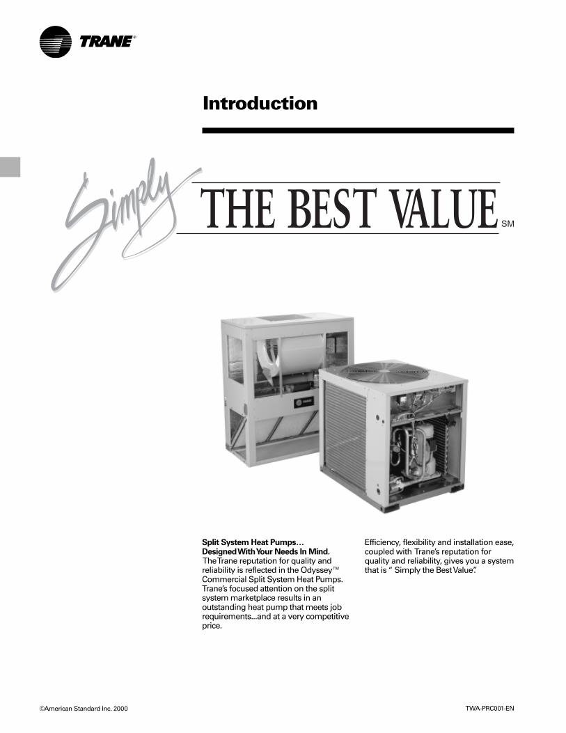
Split System Heat Pumps…Designed With Your Needs In Mind. The Trane reputation for quality andreliability is reflected in the Odyssey™Commercial Split System Heat Pumps.Trane’s focused attention on the splitsystem marketplace results in anoutstanding heat pump that meets jobrequirements...and at a very competitiveprice.
Efficiency, flexibility and installation ease,coupled with Trane’s reputation forquality and reliability, gives you a systemthat is “ Simply the Best Value”.

Contents
TWA-PRC001-EN
Introduction
Features and Benefits
Application Considerations
Selection Procedure
Model Number Description
General Data
Performance Data
Cool and Heat PerformanceFan Performance
Electric Power
Connection and Wiring
Dimension and Weights
Mechanical Specifications
2
4
6
7
89
12
122431
33
39
55
TWA-PRC001-EN4
Features andBenefits
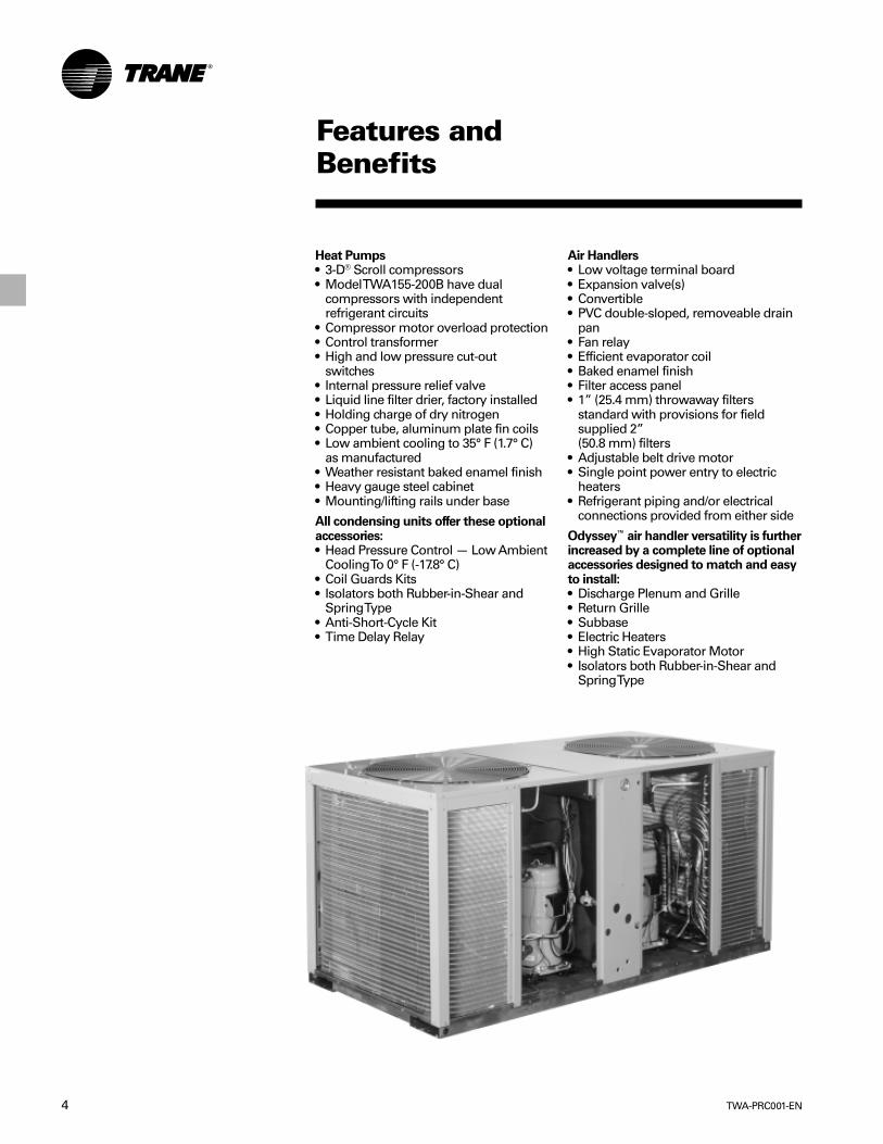
Heat Pumps• 3-D® Scroll compressors• Model TWA155-200B have dual
compressors with independentrefrigerant circuits
• Compressor motor overload protection• Control transformer• High and low pressure cut-out
switches• Internal pressure relief valve• Liquid line filter drier, factory installed• Holding charge of dry nitrogen• Copper tube, aluminum plate fin coils• Low ambient cooling to 35° F (1.7° C)
as manufactured• Weather resistant baked enamel finish• Heavy gauge steel cabinet• Mounting/lifting rails under base
All condensing units offer these optionalaccessories:• Head Pressure Control — Low Ambient
Cooling To 0° F (-17.8° C)• Coil Guards Kits• Isolators both Rubber-in-Shear and
Spring Type• Anti-Short-Cycle Kit• Time Delay Relay
Air Handlers• Low voltage terminal board• Expansion valve(s)• Convertible• PVC double-sloped, removeable drain
pan• Fan relay• Efficient evaporator coil• Baked enamel finish• Filter access panel• 1” (25.4 mm) throwaway filters
standard with provisions for fieldsupplied 2”(50.8 mm) filters
• Adjustable belt drive motor• Single point power entry to electric
heaters• Refrigerant piping and/or electrical
connections provided from either side
Odyssey™ air handler versatility is furtherincreased by a complete line of optionalaccessories designed to match and easyto install:• Discharge Plenum and Grille• Return Grille• Subbase• Electric Heaters• High Static Evaporator Motor• Isolators both Rubber-in-Shear and
Spring Type
5TWA-PRC001-EN
Features andBenefits
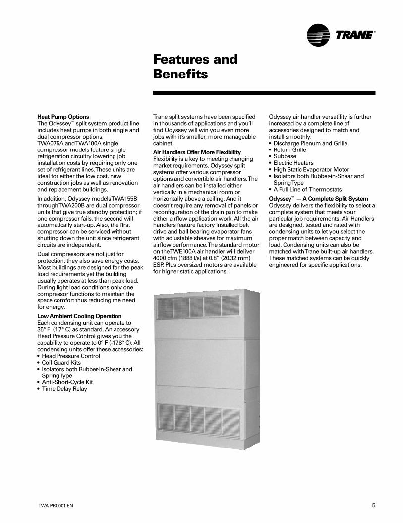
Heat Pump OptionsThe Odyssey™ split system product lineincludes heat pumps in both single anddual compressor options.TWA075A and TWA100A singlecompressor models feature singlerefrigeration circuitry lowering jobinstallation costs by requiring only oneset of refrigerant lines. These units areideal for either the low cost, newconstruction jobs as well as renovationand replacement buildings.
In addition, Odyssey models TWA155Bthrough TWA200B are dual compressorunits that give true standby protection; ifone compressor fails, the second willautomatically start-up. Also, the firstcompressor can be serviced withoutshutting down the unit since refrigerantcircuits are independent.
Dual compressors are not just forprotection, they also save energy costs.Most buildings are designed for the peakload requirements yet the buildingusually operates at less than peak load.During light load conditions only onecompressor functions to maintain thespace comfort thus reducing the needfor energy.
Low Ambient Cooling OperationEach condensing unit can operate to35° F (1.7° C) as standard. An accessoryHead Pressure Control gives you thecapability to operate to 0° F (-17.8° C). Allcondensing units offer these accessories:• Head Pressure Control• Coil Guard Kits• Isolators both Rubber-in-Shear and
Spring Type• Anti-Short-Cycle Kit• Time Delay Relay
Trane split systems have been specifiedin thousands of applications and you’llfind Odyssey will win you even morejobs with it’s smaller, more manageablecabinet.
Air Handlers Offer More FlexibilityFlexibility is a key to meeting changingmarket requirements. Odyssey splitsystems offer various compressoroptions and convertible air handlers. Theair handlers can be installed eithervertically in a mechanical room orhorizontally above a ceiling. And itdoesn’t require any removal of panels orreconfiguration of the drain pan to makeeither airflow application work. All the airhandlers feature factory installed beltdrive and ball bearing evaporator fanswith adjustable sheaves for maximumairflow performance. The standard motoron the TWE100A air handler will deliver4000 cfm (1888 l/s) at 0.8” (20.32 mm)ESP. Plus oversized motors are availablefor higher static applications.
Odyssey air handler versatility is furtherincreased by a complete line ofaccessories designed to match andinstall smoothly:• Discharge Plenum and Grille• Return Grille• Subbase• Electric Heaters• High Static Evaporator Motor• Isolators both Rubber-in-Shear and
Spring Type• A Full Line of Thermostats
Odyssey™ — A Complete Split SystemOdyssey delivers the flexibility to select acomplete system that meets yourparticular job requirements. Air Handlersare designed, tested and rated withcondensing units to let you select theproper match between capacity andload. Condensing units can also bematched with Trane built-up air handlers.These matched systems can be quicklyengineered for specific applications.

TWA-PRC001-EN6
ApplicationConsiderations
Application of this product should bewithin the catalogued airflow andperformance considerations. The SystemSelection Program will simulate productperformance for a set of givenconditions. It is recommended that theprogram should be run at the lowestoutdoor ambient and supply air flowrates requiring cooling or heatingoperation for a particular unit. For moreinformation on the System SelectionProgram contact your local TraneRepresentative.
Clearance RequirementsThe recommended clearances identifiedwith unit dimensions should bemaintained to assure adequateserviceability, maximum capacity andpeak operating efficiency. Actualclearances that appear inadequate
should be reviewed with the local TraneRepresentative.
Low Ambient CoolingAs manufactured, these units canoperate to 35° F (1.7° C) in the coolingmode of operation. An accessory head
pressure control will allow operation to0° F (-17.8° C) outdoor ambient. Whenusing these units with control systemssuch as bypass changeover Variable AirVolume, consider the requirement for ahead pressure control to allow lowambient cooling.
Typical Horizontal Air Handler Application Typical Vertical Air Handler Application
Typical Split System Application
7TWA-PRC001-EN
SelectionProcedure
Cooling CapacityStep 1 — Calculate the building’s totaland sensible cooling loads at designconditions. Use the Trane calculationform or any other standard acceptedmethod.
Step 2 — Size the equipment using TablePD-1. Match the cooling loads at designconditions.
Example: The following are the buildingcooling requirementsaElectrical Characteristics: 380-415/50/3bSummer Design Conditions: EnteringEvaporator Coil: 80 DB/67 WB(27 DB/19 WB° C)Outdoor Ambient: 95° F (35° C)cTotal Cooling Load: 75 MBh (22kW)dSensible Cooling Load: 53 MBh(15.5 kW)eAirflow: 2500 cfm (1,180 l/s)External Static Pressure: 0.77 in.
(19.6 mm) w.g. (193 Pa)
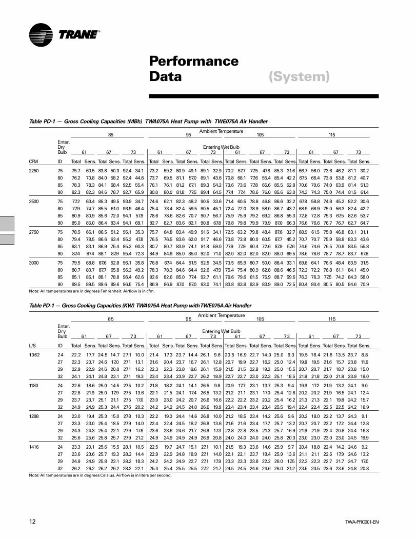
Table PD-1 shows that a TWA075Amatched with a TWE075A has a grosscooling capacity of 82.4 MBh (24.1 kW)and 59.5 MBh (17.4 kW) sensible capacityat 95 DB (35° C) ambient and 2500 cfm(1180 l/s) and 80 DB/67 WB (27 DB/19 WB)air entering the evaporator.
To find the net cooling capacities, fanmotor heat must be subtracted.Determine the total unit static pressure:
External Static0.77 in
(19.6 mm) (193 Pa)Standard Filter
0.10 in1 in. (25.4 mm)
(2.5 mm) (25 Pa) Supplementary Electric Heat0.23 in
(5.8 mm) (57 Pa) Total Static Pressure1.10 in
(27.9 mm) (275 Pa)Note: The Evaporator Fan PerformanceTable has included the effect of a 1 in.(25.4 mm) filter already. Therefore, the
actual Total Static Pressure is 1.10 - 0.10 =1.00 in. (27.9 - 2.5 = 25.4 mm)(275 - 25 = 250 Pa)
With 2500 cfm (1180 l/s) and 1.00 inches(250 Pa) (0.8 kW), Table 26-1 shows a 1.07Bhp.
Note: The formula below the table can beused to calculate Fan Motor Heat,Constant x Motor Power =Fan Motor Heat 3.5 x Bhp = MBh3.5 x 1.07 = 3.75 MBh
1.375 x (kW) = kW 1.375 x 0.8 = 1.1 kW
Net Total Cooling Capacity = 79.6 MBh – 3.75 = 75.85 MBh = 23.3 kW - 1.1 = 22.2 kWNet Sensible Cooling Capacity = 57.1 MBh – 3.75 = 53.35 MBh = 16.7 MBh - 1.1 = 15.6 kW
Heating CapacityStep 1 — Calculate the building heatingload using the Trane calculation form orany other standard accepted method.
Step 2 — Size the equipment using TablePD-9 to match the heating loads atdesign conditions. The following arebuilding heating requirements:aTotal Heating Load: 110 MBh (32.2 kW)bOutdoor Ambient (Winter): 17° F(-8.3° C) DBcIndoor Return Temperature: 70° F(21.1° C) DBdAirflow: 2500 cfm (1180 l/s)
Table PD-9 indicates the mechanicalheating portion of the heat pump willprovide 37.5 MBh (11.0 kW) for the winterdesign conditions.
Step 3 — Because 37.5 MBh (11.0 kW) isless than the building’s required heatingcapacity, a supplementary heater mustbe selected. 110 - 37.5 = 72.5 MBh (32.2 -11.0 = 21.2 kW) minimum heater capacity.
From Table PD-25, the 24.22 kW heaterhas a capacity of 82,670 Btuh. From Table34-1, the 24.22 kW heater at 400Vindicates the heater model number isBAYHTRL435A. This heater will beadequate to cover the residual heatcapacity needed for the application.
Air Delivery SelectionExternal static pressure drop through theair distribution system has beencalculated to be 0.77 inches (19.6 mm) ofwater gauge. From Table PD-24 staticpressure drop through the electric heateris 0.12 inches (3.0 mm) of water (0.77 +0.12 = .89 in.) (19.6 + 3.0 = 22.6 mm).Enter Table PD-15 for TWE090A4 at 2500cfm (1180 l/s) and .90 static pressure. Thestandard motor at 790 rpm will give thedesired airflow.
TWA-PRC001-EN8
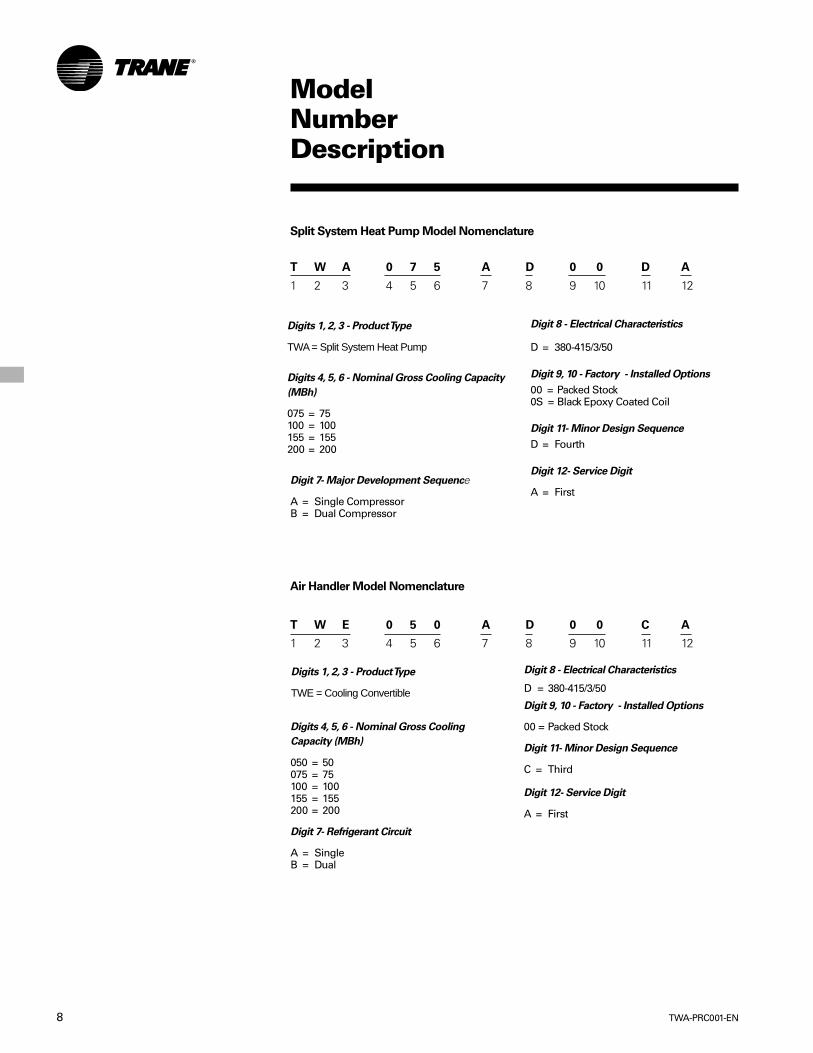
ModelNumberDescription
Digit 8 - Electrical Characteristics
D = 380-415/3/50
Digit 9, 10 - Factory - Installed Options
00 = Packed Stock0S = Black Epoxy Coated Coil
Digit 11- Minor Design Sequence
D = Fourth
Digit 12- Service Digit
A = First
Split System Heat Pump Model Nomenclature
Digit 7- Major Development Sequence
A = Single CompressorB = Dual Compressor
T W A 0 7 5 A D 0 0 D A
1 2 3 4 5 6 7 8 9 10 11 12
Air Handler Model Nomenclature
Digit 8 - Electrical Characteristics
D = 380-415/3/50
Digits 1, 2, 3 - Product Type
TWE = Cooling Convertible
Digits 4, 5, 6 - Nominal Gross Cooling
Capacity (MBh)
050 = 50075 = 75100 = 100155 = 155200 = 200
Digit 7- Refrigerant Circuit
A = SingleB = Dual
T W E 0 5 0 A D 0 0 C A
1 2 3 4 5 6 7 8 9 10 11 12
Digit 9, 10 - Factory - Installed Options
00 = Packed Stock
Digit 11- Minor Design Sequence
C = Third
Digit 12- Service Digit
A = First
Digits 4, 5, 6 - Nominal Gross Cooling Capacity
(MBh)
075 = 75100 = 100155 = 155200 = 200
Digits 1, 2, 3 - Product Type
TWA = Split System Heat Pump

9TWA-PRC001-EN
GeneralData (Heat Pumps)
Table GD-1 — General Data — Heat Pumps
TWA075A TWA100ACooling Performance1
Gross Cooling Capacity, BTUH (KW)Matched Air Handler, BTUH (KW) 82,000 (23.97) 109,000 (31.97)Heat Pump Only2, BTUH (KW) 82,000 (23.97) 105,000 (30.75)
ARI Net Cooling Capacity3 80,000 (23.35) 105,000 (30.75)System Power KW 7.36 10.32Heat Pump Only Power KW 6.61 9.22
Heating PerformanceARI Heating with Matched Air HandlerHigh Temperature Capacity, BTUH (KW) 75,000 (21.82) 106,000 (31.05)Low Temperature Capacity, BTUH (KW) 47,000 (13.84) 69,000 (20.29)
CompressorNumber 1 1Type 3D®Scroll 3D®ScrollNo. Speeds 1 1No. Motors 1 1Motor HP (KW) 6.25 (4.7) 8.33 (6.21)Motor RPM 2875 2875
ARI Sound Rating (Bels)4 8.8 8.8System Data5
No. Refrigerant Circuits 1 1Suction Line, in. (mm) OD 1.375 (34.9) 1.375 (34.9)Liquid Line, in. (mm) OD 0.500 (12.7) 0.500 (12.7)
Outdoor Coil — Type Plate Fin Plate FinTube Size, in. (mm) OD 0.375 (9.5) 0.375 (9.5)Face Area, sq. ft. (m2) 19.2 (1.78) 24.0 (2.23)Rows 2 2Fins Per Inch (Fins per mm) 18 (457) 18 (457)
Outdoor Fan Type Propeller PropellerNo. Used 1 1Diameter, in. (mm) 26.00 (660.4) 28.00 (711)Drive Type Direct DirectNo. Speeds 1 1CFM6, (L/S) 4700 (2218.2) 6700 (3161.7)No. Motors 1 1Motor HP (KW) 0.33 (.24) 0.75 (.56)Motor RPM 925 925
R-22 Refrigerant Charge, Lbs7 (Kg) 18.0 (8.16) 24.25 (11.0)Notes:1. Cooling Performance is rated at 95° F (35° C) ambient, 80° F (26.7° C) entering dry bulb, 67° F (19.4° C) entering wet
bulb and nominal cfm listed. ARI rating cfm is 350 cfm/ton for this product. Gross capacity does not include theeffect of fan motor heat. ARI capacity is net and includes the effect of fan motor heat. Units are suitable foroperation to ±20% of nominal cfm. Rated accordance with ARI Standard 210.
2. Condensing Unit Only Gross Cooling Capacity rated at 45° F (7.2° C) saturated suction temperature and at 95° F(35° C) ambient.
3. ARI Net Cooling Capacity is calculated with matched blower coil and 25 ft. (7.2 m) of 1.375, 0.500 OD interconnect-ing tubing. EER and/or SEER are rated at ARI conditions and in accordance with DOE test procedures. IntegratedPart Load Value is based on ARI Standard 210/240/340. Units are rated at 80° F (26.7° C) ambient, 80° F (26.7° C)entering dry bulb, and 67° F (19.4° C) entering wet bulb at ARI rated cfm.
4. ARI Sound Rating is rated in accordance with ARI Standard 270.5. System Data based on maximum linear length 80 ft. (26.7 m)Maximum lift: suction 60 ft. (18.3 m) liquid 60 ft. (18.3
m) For greater lengths, refer to refrigerant piping applications manual.6. Outdoor Fan Cfm is rated with standard air-dry coil outdoor.7. Refrigerant (operating) charge is for condensing unit (all circuits) with matching blower coils and 25 ft. (7.6 m) of
interconnecting refrigerant lines.

TWA-PRC001-EN10
GeneralData (Heat Pumps)
Table GD-2 General Data — Heat Pumps
TWA155B TWA200BCooling Performance1
Gross Cooling Capacity, BTUH (KW)Matched Air Handler, BTUH (KW) 166,000 (48.57) 216,000 (63.24)Condensing Unit Only2, BTUH (KW) 161,000 (47.04) 209,000 (61.18)
ARI Net Cooling Capacity3 160,000 (46.74) 196,000 (61.18)System Power KW 14.98 20.61Condensing Unit Power KW 13.20 18.52
Heating PerformanceARI Heating with Matched Air HandlerHigh Temperature Capacity, BTUH (KW) 151,000 (44.27) 206,000 (60.26)Low Temperature Capacity, BTUH (KW) 95,000 (27.67) 135,000 (39.66)
CompressorNumber 2 2Type 3D®Scroll 3D®ScrollNo. Speeds 1 1No. Motors 2 2Motor HP 6.25 (4.7) 8.33 (6.21)Motor RPM, (KW) 2875 2875
ARI Sound Rating (Bels)4 8.8 8.8System Data5
No. Refrigerant Circuits 2 2Suction Line, in. (mm) OD 1.375 (34.9) 1.375 (34.9)Liquid Line, in. (mm) OD 0.500 (12.7) 0.500 (12.7)
Outdoor Coil — Type Plate Fin Plate FinTube Size, in. (mm) OD 0.375 (9.5) 0.375 (9.5)Face Area, sq. ft. (m2) 38.4 (3.57) 48.0 (4.46)Rows 2 2Fins Per Inch(mm) 18 (457) 18 (457)
Outdoor Fan Type Propeller/Propeller Propeller/PropellerNo. Used 2 2Diameter, in. (mm) 26.00/26.00 (660.4/660.4) 28.00/28.00 (711/711)Drive Type Direct/Direct Direct/DirectNo. Speeds 1 1CFM6, (L/S) 9800 (4624.6) 13400 (6323.5)No. Motors 2 2Motor HP, (KW) 0.33 (.24) 0.75 (.56)Motor RPM 925 925
R-22 Refrigerant Charge, Lbs7 (Kg) 36.0 (16.32) 48.5 (22.0)Notes:1. Cooling Performance is rated at 95° F (35° C) ambient, 80° F (26.7° C) entering dry bulb, 67° F (19.4° C) entering
wet bulb and nominal cfm listed. ARI rating cfm is 350 cfm/ton for this product. Gross capacity does not includethe effect of fan motor heat. ARI capacity is net and includes the effect of fan motor heat. Units are suitable foroperation to ±20% of nominal cfm. Rated accordance with ARI Standard 210.
2. Condensing Unit Only Gross Cooling Capacity rated at 45° F (7.6° C) saturated suction temperature and at 95° F(35° C) ambient.
3. ARI Net Cooling Capacity is calculated with matched blower coil and 25 ft. (7.6 m) of 1.375, 0.500 OD interconnect-ing tubing. EER and/or SEER are rated at ARI conditions and in accordance with DOE test procedures. IntegratedPart Load Value is based on ARI Standard 210/240/340. Units are rated at 80° F (26.7° C) ambient, 80° F (26.7° C)entering dry bulb, and 67° F (19.4° C) entering wet bulb at ARI rated cfm.
4. ARI Sound Rating is rated in accordance with ARI Standard 270.5. System Data based on maximum linear length 80 ft. (26.7 m)Maximum lift: suction 60 ft. (18.3 m) liquid 60 ft. (18.3
m) For greater lengths, refer to refrigerant piping applications manual.6. Outdoor Fan Cfm is rated with standard air-dry coil outdoor.7. Refrigerant (operating) charge is for condensing unit (all circuits) with matching blower coils and 25 ft. (7.6 m) of
interconnecting refrigerant lines.
11TWA-PRC001-EN
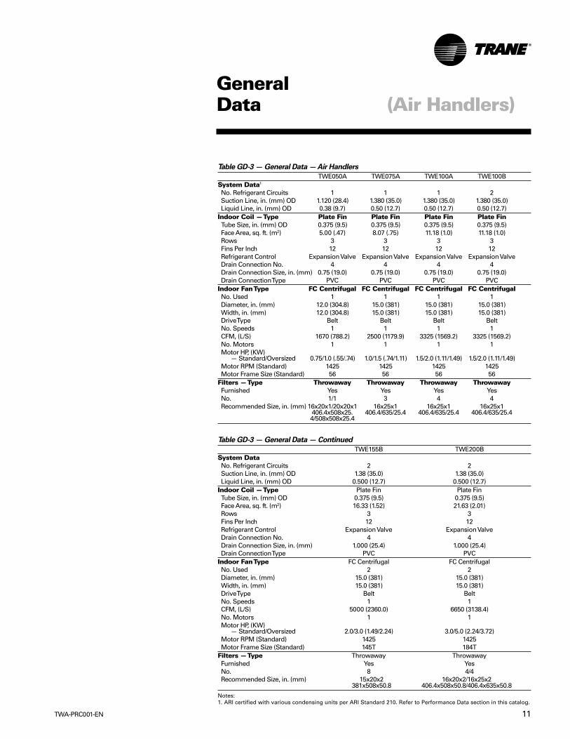
Table GD-3 — General Data — Air Handlers
TWE050A TWE075A TWE100A TWE100BSystem Data1
No. Refrigerant Circuits 1 1 1 2Suction Line, in. (mm) OD 1.120 (28.4) 1.380 (35.0) 1.380 (35.0) 1.380 (35.0)Liquid Line, in. (mm) OD 0.38 (9.7) 0.50 (12.7) 0.50 (12.7) 0.50 (12.7)
Indoor Coil — Type Plate Fin Plate Fin Plate Fin Plate FinTube Size, in. (mm) OD 0.375 (9.5) 0.375 (9.5) 0.375 (9.5) 0.375 (9.5)Face Area, sq. ft. (m2) 5.00 (.47) 8.07 (.75) 11.18 (1.0) 11.18 (1.0)Rows 3 3 3 3Fins Per Inch 12 12 12 12Refrigerant Control Expansion Valve Expansion Valve Expansion Valve Expansion ValveDrain Connection No. 4 4 4 4Drain Connection Size, in. (mm) 0.75 (19.0) 0.75 (19.0) 0.75 (19.0) 0.75 (19.0)Drain Connection Type PVC PVC PVC PVC
Indoor Fan Type FC Centrifugal FC Centrifugal FC Centrifugal FC CentrifugalNo. Used 1 1 1 1Diameter, in. (mm) 12.0 (304.8) 15.0 (381) 15.0 (381) 15.0 (381)Width, in. (mm) 12.0 (304.8) 15.0 (381) 15.0 (381) 15.0 (381)Drive Type Belt Belt Belt BeltNo. Speeds 1 1 1 1CFM, (L/S) 1670 (788.2) 2500 (1179.9) 3325 (1569.2) 3325 (1569.2)No. Motors 1 1 1 1Motor HP, (KW)
— Standard/Oversized 0.75/1.0 (.55/.74) 1.0/1.5 (.74/1.11) 1.5/2.0 (1.11/1.49) 1.5/2.0 (1.11/1.49)Motor RPM (Standard) 1425 1425 1425 1425Motor Frame Size (Standard) 56 56 56 56
Filters — Type Throwaway Throwaway Throwaway ThrowawayFurnished Yes Yes Yes YesNo. 1/1 3 4 4Recommended Size, in. (mm) 16x20x1/20x20x1 16x25x1 16x25x1 16x25x1
406.4x508x25. 406.4/635/25.4 406.4/635/25.4 406.4/635/25.44/508x508x25.4
Table GD-3 — General Data — Continued
TWE155B TWE200BSystem DataNo. Refrigerant Circuits 2 2Suction Line, in. (mm) OD 1.38 (35.0) 1.38 (35.0)Liquid Line, in. (mm) OD 0.500 (12.7) 0.500 (12.7)
Indoor Coil — Type Plate Fin Plate FinTube Size, in. (mm) OD 0.375 (9.5) 0.375 (9.5)Face Area, sq. ft. (m2) 16.33 (1.52) 21.63 (2.01)Rows 3 3Fins Per Inch 12 12Refrigerant Control Expansion Valve Expansion ValveDrain Connection No. 4 4Drain Connection Size, in. (mm) 1.000 (25.4) 1.000 (25.4)Drain Connection Type PVC PVC
Indoor Fan Type FC Centrifugal FC CentrifugalNo. Used 2 2Diameter, in. (mm) 15.0 (381) 15.0 (381)Width, in. (mm) 15.0 (381) 15.0 (381)Drive Type Belt BeltNo. Speeds 1 1CFM, (L/S) 5000 (2360.0) 6650 (3138.4)No. Motors 1 1Motor HP, (KW)
— Standard/Oversized 2.0/3.0 (1.49/2.24) 3.0/5.0 (2.24/3.72)Motor RPM (Standard) 1425 1425Motor Frame Size (Standard) 145T 184T
Filters — Type Throwaway ThrowawayFurnished Yes YesNo. 8 4/4Recommended Size, in. (mm) 15x20x2 16x20x2/16x25x2
381x508x50.8 406.4x508x50.8/406.4x635x50.8
Notes:1. ARI certified with various condensing units per ARI Standard 210. Refer to Performance Data section in this catalog.
GeneralData (Air Handlers)
TWA-PRC001-EN12
PerformanceData (System)
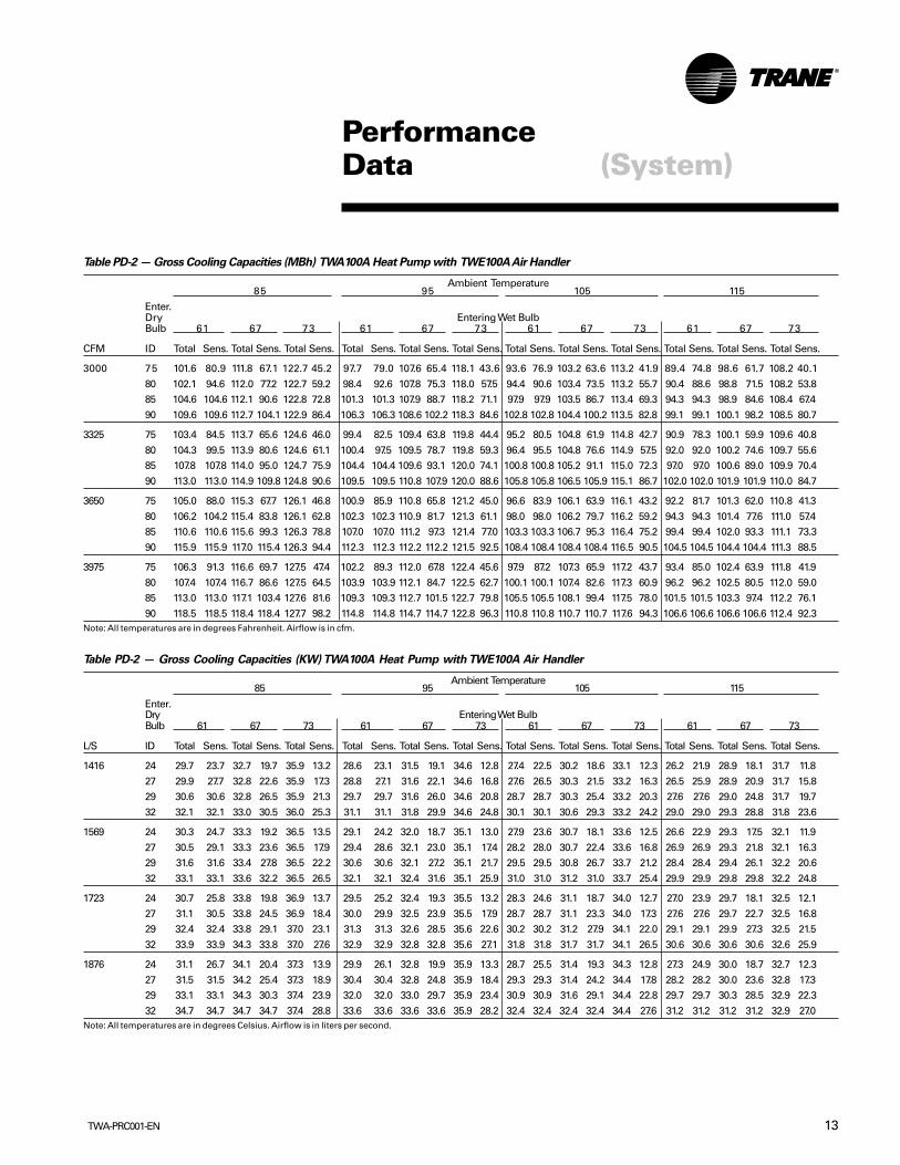
Table PD-1 — Gross Cooling Capacities (MBh) TWA075A Heat Pump with TWE075A Air Handler
Ambient Temperature85 95 105 115
Enter.Dry Entering Wet BulbBulb 61 67 73 61 67 73 61 67 73 61 67 73
CFM ID Total Sens. Total Sens. Total Sens. Total Sens. Total Sens. Total Sens. Total Sens. Total Sens. Total Sens. Total Sens. Total Sens. Total Sens.
2250 75 75.7 60.5 83.8 50.3 92.4 34.1 73.2 59.2 80.9 49.1 89.1 32.9 70.2 57.7 77.5 47.8 85.3 31.6 66.7 56.0 73.6 46.2 81.1 30.2
80 76.2 70.8 84.0 58.2 92.4 44.8 73.7 69.5 81.1 57.0 89.1 43.6 70.8 68.1 77.6 55.4 85.4 42.2 67.5 66.4 73.8 53.8 81.2 40.785 78.3 78.3 84.1 68.4 92.5 55.4 76.1 76.1 81.2 67.1 89.3 54.2 73.6 73.6 77.8 65.6 85.5 52.8 70.6 70.6 74.0 63.9 81.4 51.3
90 82.3 82.3 84.6 78.7 92.7 65.9 80.0 80.0 81.8 77.5 89.4 64.5 77.4 77.4 78.6 76.0 85.6 63.0 74.3 74.3 75.0 74.4 81.5 61.4
2500 75 77.2 63.4 85.3 49.5 93.9 34.7 74.6 62.1 82.3 48.2 90.5 33.6 71.4 60.5 78.8 46.8 86.6 32.2 67.8 58.8 74.8 45.2 82.2 30.6
80 77.9 74.7 85.5 61.0 93.9 46.4 75.4 73.4 82.4 59.5 90.5 45.1 72.4 72.0 78.9 58.0 86.7 43.7 68.9 68.9 75.0 56.3 82.4 42.285 80.9 80.9 85.6 72.0 94.1 57.9 78.6 78.6 82.6 70.7 90.7 56.7 75.9 75.9 79.2 69.2 86.8 55.3 72.8 72.8 75.3 67.5 82.6 53.7
90 85.0 85.0 86.4 83.4 94.1 69.1 82.7 82.7 83.6 82.1 90.8 67.8 79.8 79.8 79.9 79.9 87.0 66.3 76.6 76.6 76.7 76.7 82.7 64.7
2750 75 78.5 66.1 86.5 51.2 95.1 35.3 75.7 64.8 83.4 49.9 91.6 34.1 72.5 63.2 79.8 48.4 87.6 32.7 68.9 61.5 75.8 46.8 83.1 31.1
80 79.4 78.5 86.6 63.4 95.2 47.8 76.5 76.5 83.6 62.0 91.7 46.6 73.8 73.8 80.0 60.5 87.7 45.2 70.7 70.7 75.9 58.8 83.3 43.685 83.1 83.1 86.9 75.4 95.3 60.3 80.7 80.7 83.9 74.1 91.8 59.0 77.9 77.9 80.4 72.6 87.9 57.6 74.6 74.6 76.5 70.9 83.5 55.8
90 87.4 87.4 88.1 87.9 95.4 72.3 84.9 84.9 85.0 85.0 92.0 71.0 82.0 82.0 82.0 82.0 88.0 69.5 78.6 78.6 78.7 78.7 83.7 67.8
3000 75 79.5 68.8 87.6 52.8 96.1 35.8 76.8 67.4 84.4 51.5 92.5 34.5 73.5 65.9 80.7 50.0 88.4 33.1 69.8 64.1 76.6 48.4 83.9 31.5
80 80.7 80.7 87.7 65.8 96.2 49.2 78.3 78.3 84.6 64.4 92.6 47.9 75.4 75.4 80.9 62.8 88.6 46.5 72.2 72.2 76.8 61.1 84.1 45.085 85.1 85.1 88.1 78.8 96.4 62.6 82.6 82.6 85.0 77.4 92.7 61.1 79.6 79.6 81.5 75.9 88.7 59.6 76.3 76.3 77.5 74.2 84.3 58.0
90 89.5 89.5 89.6 89.6 96.5 75.4 86.9 86.9 87.0 87.0 93.0 74.1 83.8 83.8 83.9 83.9 89.0 72.5 80.4 80.4 80.5 80.5 84.6 70.9Note: All temperatures are in degrees Fahrenheit. Airflow is in cfm.
Table PD-1 — Gross Cooling Capacities (KW) TWA075A Heat Pump with TWE075A Air Handler
Ambient Temperature85 95 105 115
Enter.Dry Entering Wet BulbBulb 61 67 73 61 67 73 61 67 73 61 67 73
L/S ID Total Sens. Total Sens. Total Sens. Total Sens. Total Sens. Total Sens. Total Sens. Total Sens. Total Sens. Total Sens. Total Sens. Total Sens.
1062 24 22.2 17.7 24.5 14.7 27.1 10.0 21.4 17.3 23.7 14.4 26.1 9.6 20.5 16.9 22.7 14.0 25.0 9.3 19.5 16.4 21.6 13.5 23.7 8.8
27 22.3 20.7 24.6 17.0 27.1 13.1 21.6 20.4 23.7 16.7 26.1 12.8 20.7 19.9 22.7 16.2 25.0 12.4 19.8 19.5 21.6 15.7 23.8 11.929 22.9 22.9 24.6 20.0 27.1 16.2 22.3 22.3 23.8 19.6 26.1 15.9 21.5 21.5 22.8 19.2 25.0 15.5 20.7 20.7 21.7 18.7 23.8 15.0
32 24.1 24.1 24.8 23.1 27.1 19.3 23.4 23.4 23.9 22.7 26.2 18.9 22.7 22.7 23.0 22.3 25.1 18.5 21.8 21.8 22.0 21.8 23.9 18.0
1180 24 22.6 18.6 25.0 14.5 27.5 10.2 21.8 18.2 24.1 14.1 26.5 9.8 20.9 17.7 23.1 13.7 25.3 9.4 19.9 17.2 21.9 13.2 24.1 9.0
27 22.8 21.9 25.0 17.9 27.5 13.6 22.1 21.5 24.1 17.4 26.5 13.2 21.2 21.1 23.1 17.0 25.4 12.8 20.2 20.2 21.9 16.5 24.1 12.429 23.7 23.7 25.1 21.1 27.5 17.0 23.0 23.0 24.2 20.7 26.6 16.6 22.2 22.2 23.2 20.2 25.4 16.2 21.3 21.3 22.1 19.8 24.2 15.7
32 24.9 24.9 25.3 24.4 27.6 20.2 24.2 24.2 24.5 24.0 26.6 19.9 23.4 23.4 23.4 23.4 25.5 19.4 22.4 22.4 22.5 22.5 24.2 18.9
1298 24 23.0 19.4 25.3 15.0 27.8 10.3 22.2 19.0 24.4 14.6 26.8 10.0 21.2 18.5 23.4 14.2 25.6 9.6 20.2 18.0 22.2 13.7 24.3 9.1
27 23.3 23.0 25.4 18.5 27.9 14.0 22.4 22.4 24.5 18.2 26.8 13.6 21.6 21.6 23.4 17.7 25.7 13.2 20.7 20.7 22.2 17.2 24.4 12.829 24.3 24.3 25.4 22.1 27.9 17.6 23.6 23.6 24.6 21.7 26.9 17.3 22.8 22.8 23.5 21.3 25.7 16.9 21.9 21.9 22.4 20.8 24.4 16.3
32 25.6 25.6 25.8 25.7 27.9 21.2 24.9 24.9 24.9 24.9 26.9 20.8 24.0 24.0 24.0 24.0 25.8 20.3 23.0 23.0 23.0 23.0 24.5 19.9
1416 24 23.3 20.1 25.6 15.5 28.1 10.5 22.5 19.7 24.7 15.1 27.1 10.1 21.5 19.3 23.6 14.6 25.9 9.7 20.4 18.8 22.4 14.2 24.6 9.2
27 23.6 23.6 25.7 19.3 28.2 14.4 22.9 22.9 24.8 18.9 27.1 14.0 22.1 22.1 23.7 18.4 25.9 13.6 21.1 21.1 22.5 17.9 24.6 13.229 24.9 24.9 25.8 23.1 28.2 18.3 24.2 24.2 24.9 22.7 27.1 17.9 23.3 23.3 23.8 22.2 26.0 17.5 22.3 22.3 22.7 21.7 24.7 17.0
32 26.2 26.2 26.2 26.2 28.2 22.1 25.4 25.4 25.5 25.5 27.2 21.7 24.5 24.5 24.6 24.6 26.0 21.2 23.5 23.5 23.6 23.6 24.8 20.8Note: All temperatures are in degrees Celsius. Airflow is in liters per second.
13TWA-PRC001-EN
PerformanceData (System)
Table PD-2 — Gross Cooling Capacities (MBh) TWA100A Heat Pump with TWE100A Air Handler
Ambient Temperature85 95 105 115
Enter.Dry Entering Wet BulbBulb 61 67 73 61 67 73 61 67 73 61 67 73
CFM ID Total Sens. Total Sens. Total Sens. Total Sens. Total Sens. Total Sens. Total Sens. Total Sens. Total Sens. Total Sens. Total Sens. Total Sens.
3000 75 101.6 80.9 111.8 67.1 122.7 45.2 97.7 79.0 107.6 65.4 118.1 43.6 93.6 76.9 103.2 63.6 113.2 41.9 89.4 74.8 98.6 61.7 108.2 40.1
80 102.1 94.6 112.0 77.2 122.7 59.2 98.4 92.6 107.8 75.3 118.0 57.5 94.4 90.6 103.4 73.5 113.2 55.7 90.4 88.6 98.8 71.5 108.2 53.885 104.6 104.6 112.1 90.6 122.8 72.8 101.3 101.3 107.9 88.7 118.2 71.1 97.9 97.9 103.5 86.7 113.4 69.3 94.3 94.3 98.9 84.6 108.4 67.4
90 109.6 109.6 112.7 104.1 122.9 86.4 106.3 106.3 108.6 102.2 118.3 84.6 102.8 102.8 104.4 100.2 113.5 82.8 99.1 99.1 100.1 98.2 108.5 80.7
3325 75 103.4 84.5 113.7 65.6 124.6 46.0 99.4 82.5 109.4 63.8 119.8 44.4 95.2 80.5 104.8 61.9 114.8 42.7 90.9 78.3 100.1 59.9 109.6 40.8
80 104.3 99.5 113.9 80.6 124.6 61.1 100.4 97.5 109.5 78.7 119.8 59.3 96.4 95.5 104.8 76.6 114.9 57.5 92.0 92.0 100.2 74.6 109.7 55.685 107.8 107.8 114.0 95.0 124.7 75.9 104.4 104.4 109.6 93.1 120.0 74.1 100.8 100.8 105.2 91.1 115.0 72.3 97.0 97.0 100.6 89.0 109.9 70.4
90 113.0 113.0 114.9 109.8 124.8 90.6 109.5 109.5 110.8 107.9 120.0 88.6 105.8 105.8 106.5 105.9 115.1 86.7 102.0 102.0 101.9 101.9 110.0 84.7
3650 75 105.0 88.0 115.3 67.7 126.1 46.8 100.9 85.9 110.8 65.8 121.2 45.0 96.6 83.9 106.1 63.9 116.1 43.2 92.2 81.7 101.3 62.0 110.8 41.3
80 106.2 104.2 115.4 83.8 126.1 62.8 102.3 102.3 110.9 81.7 121.3 61.1 98.0 98.0 106.2 79.7 116.2 59.2 94.3 94.3 101.4 77.6 111.0 57.485 110.6 110.6 115.6 99.3 126.3 78.8 107.0 107.0 111.2 97.3 121.4 77.0 103.3 103.3 106.7 95.3 116.4 75.2 99.4 99.4 102.0 93.3 111.1 73.3
90 115.9 115.9 117.0 115.4 126.3 94.4 112.3 112.3 112.2 112.2 121.5 92.5 108.4 108.4 108.4 108.4 116.5 90.5 104.5 104.5 104.4 104.4 111.3 88.5
3975 75 106.3 91.3 116.6 69.7 127.5 47.4 102.2 89.3 112.0 67.8 122.4 45.6 97.9 87.2 107.3 65.9 117.2 43.7 93.4 85.0 102.4 63.9 111.8 41.9
80 107.4 107.4 116.7 86.6 127.5 64.5 103.9 103.9 112.1 84.7 122.5 62.7 100.1 100.1 107.4 82.6 117.3 60.9 96.2 96.2 102.5 80.5 112.0 59.085 113.0 113.0 117.1 103.4 127.6 81.6 109.3 109.3 112.7 101.5 122.7 79.8 105.5 105.5 108.1 99.4 117.5 78.0 101.5 101.5 103.3 97.4 112.2 76.1
90 118.5 118.5 118.4 118.4 127.7 98.2 114.8 114.8 114.7 114.7 122.8 96.3 110.8 110.8 110.7 110.7 117.6 94.3 106.6 106.6 106.6 106.6 112.4 92.3Note: All temperatures are in degrees Fahrenheit. Airflow is in cfm.
Table PD-2 — Gross Cooling Capacities (KW) TWA100A Heat Pump with TWE100A Air Handler
Ambient Temperature85 95 105 115
Enter.Dry Entering Wet BulbBulb 61 67 73 61 67 73 61 67 73 61 67 73
L/S ID Total Sens. Total Sens. Total Sens. Total Sens. Total Sens. Total Sens. Total Sens. Total Sens. Total Sens. Total Sens. Total Sens. Total Sens.
1416 24 29.7 23.7 32.7 19.7 35.9 13.2 28.6 23.1 31.5 19.1 34.6 12.8 27.4 22.5 30.2 18.6 33.1 12.3 26.2 21.9 28.9 18.1 31.7 11.8
27 29.9 27.7 32.8 22.6 35.9 17.3 28.8 27.1 31.6 22.1 34.6 16.8 27.6 26.5 30.3 21.5 33.2 16.3 26.5 25.9 28.9 20.9 31.7 15.829 30.6 30.6 32.8 26.5 35.9 21.3 29.7 29.7 31.6 26.0 34.6 20.8 28.7 28.7 30.3 25.4 33.2 20.3 27.6 27.6 29.0 24.8 31.7 19.7
32 32.1 32.1 33.0 30.5 36.0 25.3 31.1 31.1 31.8 29.9 34.6 24.8 30.1 30.1 30.6 29.3 33.2 24.2 29.0 29.0 29.3 28.8 31.8 23.6
1569 24 30.3 24.7 33.3 19.2 36.5 13.5 29.1 24.2 32.0 18.7 35.1 13.0 27.9 23.6 30.7 18.1 33.6 12.5 26.6 22.9 29.3 17.5 32.1 11.9
27 30.5 29.1 33.3 23.6 36.5 17.9 29.4 28.6 32.1 23.0 35.1 17.4 28.2 28.0 30.7 22.4 33.6 16.8 26.9 26.9 29.3 21.8 32.1 16.329 31.6 31.6 33.4 27.8 36.5 22.2 30.6 30.6 32.1 27.2 35.1 21.7 29.5 29.5 30.8 26.7 33.7 21.2 28.4 28.4 29.4 26.1 32.2 20.6
32 33.1 33.1 33.6 32.2 36.5 26.5 32.1 32.1 32.4 31.6 35.1 25.9 31.0 31.0 31.2 31.0 33.7 25.4 29.9 29.9 29.8 29.8 32.2 24.8
1723 24 30.7 25.8 33.8 19.8 36.9 13.7 29.5 25.2 32.4 19.3 35.5 13.2 28.3 24.6 31.1 18.7 34.0 12.7 27.0 23.9 29.7 18.1 32.5 12.1
27 31.1 30.5 33.8 24.5 36.9 18.4 30.0 29.9 32.5 23.9 35.5 17.9 28.7 28.7 31.1 23.3 34.0 17.3 27.6 27.6 29.7 22.7 32.5 16.829 32.4 32.4 33.8 29.1 37.0 23.1 31.3 31.3 32.6 28.5 35.6 22.6 30.2 30.2 31.2 27.9 34.1 22.0 29.1 29.1 29.9 27.3 32.5 21.5
32 33.9 33.9 34.3 33.8 37.0 27.6 32.9 32.9 32.8 32.8 35.6 27.1 31.8 31.8 31.7 31.7 34.1 26.5 30.6 30.6 30.6 30.6 32.6 25.9
1876 24 31.1 26.7 34.1 20.4 37.3 13.9 29.9 26.1 32.8 19.9 35.9 13.3 28.7 25.5 31.4 19.3 34.3 12.8 27.3 24.9 30.0 18.7 32.7 12.3
27 31.5 31.5 34.2 25.4 37.3 18.9 30.4 30.4 32.8 24.8 35.9 18.4 29.3 29.3 31.4 24.2 34.4 17.8 28.2 28.2 30.0 23.6 32.8 17.329 33.1 33.1 34.3 30.3 37.4 23.9 32.0 32.0 33.0 29.7 35.9 23.4 30.9 30.9 31.6 29.1 34.4 22.8 29.7 29.7 30.3 28.5 32.9 22.3
32 34.7 34.7 34.7 34.7 37.4 28.8 33.6 33.6 33.6 33.6 35.9 28.2 32.4 32.4 32.4 32.4 34.4 27.6 31.2 31.2 31.2 31.2 32.9 27.0Note: All temperatures are in degrees Celsius. Airflow is in liters per second.
TWA-PRC001-EN14
PerformanceData (System)
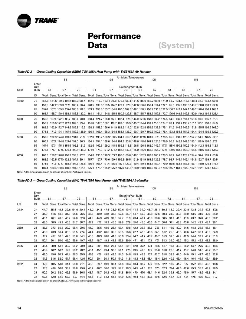
Table PD-3 — Gross Cooling Capacities (MBh) TWA155A Heat Pump with TWE155A Air Handler
Ambient Temperature85 95 105 115
Enter.Dry Entering Wet Bulb
CFM Bulb 61 67 73 61 67 73 61 67 73 61 67 73
ID Total Sens. Total Sens. Total Sens. Total Sens. Total Sens. Total Sens. Total Sens. Total Sens. Total Sens. Total Sens. Total Sens. Total Sens.
4500 75 152.8 121.6169.0 101.2 186.3 68.7 147.6 119.0 163.1 98.8 179.6 66.4 141.5 116.0 156.2 96.0 171.9 63.7 134.4 112.5 148.4 92.9 163.4 60.8
80 153.5 142.2 169.3 117.1 186.4 90.4 148.5 139.6 163.5 114.7 179.7 87.9 142.6 136.6 156.4 111.4 172.1 85.0 135.8 133.3 148.7 108.0 163.7 82.085 157.6 157.6 169.5 137.4 186.6 111.5 153.3 153.3 163.7 134.8 180.0 109.0 148.1 148.1 156.9 131.8 172.5 106.2 142.1 142.1 149.2 128.4 164.1 103.1
90 165.7 165.7 170.4 158.1 186.8 132.2 161.1 161.1 164.8 155.5 180.2 129.6 155.7 155.7 158.2 152.6 172.7 126.6 149.6 149.6 150.9 149.3 164.3 123.4
5000 75 155.8 127.4 172.1 99.7 189.4 70.0 150.4 124.7 166.0 97.1 182.4 67.6 144.0 121.6 158.8 94.2 174.5 64.9 136.7 118.1 150.8 90.9 165.7 61.8
80 156.9 150.0 172.2 122.3 189.5 93.4 151.8 147.5 166.1 119.7 182.6 90.9 145.7 144.4 159.1 116.6 174.7 88.1 138.7 138.7 151.1 113.1 166.0 84.985 162.9 162.9 172.7 144.6 189.8 116.5 158.3 158.3 166.6 141.9 182.9 114.0 152.8 152.8 159.6 138.9 175.1 111.2 146.5 146.5 151.8 135.5 166.5 108.0
90 171.3 171.3 174.1 167.4 189.9 138.9 166.4 166.4 168.3 164.8 183.1 136.2 160.7 160.7 160.9 160.9 175.4 133.2 154.3 154.3 154.4 154.4 166.8 129.9
5500 75 158.3 132.9 174.6 103.0 191.8 71.3 152.8 130.2 168.3 100.5 184.7 68.7 146.2 127.0 161.0 97.5 176.5 65.9 138.8 123.5 152.7 94.2 167.5 62.7
80 160.1 157.7 174.8 127.4 192.0 96.3 154.1 154.1 168.6 124.6 184.9 93.8 148.6 148.6 161.3 121.5 176.9 90.9 142.3 142.3 153.1 118.0 168.0 87.885 167.4 167.4 175.3 151.5 192.3 121.3 162.6 162.6 169.2 148.8 185.3 118.8 156.8 156.8 162.0 145.7 177.1 115.4 150.3 150.3 154.0 142.3 168.3 112.1
90 176.1 176.1 177.5 176.4 192.6 145.3 171.0 171.0 171.2 171.2 185.6 142.6 165.0 165.0 165.2 165.2 177.6 139.6 158.3 158.3 158.5 158.5 168.9 136.2
6000 75 160.5 138.2 176.8 106.3 193.9 72.2 154.8 135.5 170.3 103.7 186.6 69.6 148.1 132.3 162.8 100.7 178.3 66.7 140.6 128.7 154.4 97.4 169.1 63.6
80 162.6 162.5 177.0 132.2 194.1 99.1 157.7 157.7 170.6 129.4 186.9 96.5 151.9 151.9 163.2 126.3 178.7 93.7 145.4 145.4 154.8 122.7 169.7 90.585 171.5 171.5 177.7 158.2 194.3 125.6 166.4 166.4 171.4 155.5 187.1 122.9 160.4 160.4 164.1 152.4 179.0 119.8 153.6 153.6 156.1 148.9 170.1 116.4
90 180.4 180.4 180.6 180.6 194.8 151.5 175.1 175.1 175.2 175.2 187.6 148.8 168.9 168.9 169.0 169.0 179.5 145.7 161.9 161.9 162.1 162.1 170.6 142.3Note: All temperatures are in degrees Fahrenheit. Airflow is in cfm.
Table PD-3 — Gross Cooling Capacities (KW) TWA155A Heat Pump with TWE155A Air Handler
Ambient Temperature85 95 105 115
Enter.Dry Entering Wet BulbBulb 61 67 73 61 67 73 61 67 73 61 67 73
L/S ID Total Sens. Total Sens. Total Sens. Total Sens. Total Sens. Total Sens. Total Sens. Total Sens. Total Sens. Total Sens. Total Sens. Total Sens.
2124 24 44.7 35.6 49.5 29.6 54.6 20.1 43.2 34.8 47.8 28.9 52.6 19.4 41.4 34.0 45.7 28.1 50.3 18.7 39.4 32.9 43.5 27.2 47.8 17.8
27 44.9 41.6 49.6 34.3 54.6 26.5 43.5 40.9 47.9 33.6 52.6 25.7 41.7 40.0 45.8 32.6 50.4 24.9 39.8 39.0 43.5 31.6 47.9 24.029 46.1 46.1 49.6 40.2 54.6 32.6 44.9 44.9 47.9 39.5 52.7 31.9 43.4 43.4 45.9 38.6 50.5 31.1 41.6 41.6 43.7 37.6 48.0 30.2
32 48.5 48.5 49.9 46.3 54.7 38.7 47.2 47.2 48.2 45.5 52.8 37.9 45.6 45.6 46.3 44.7 50.6 37.1 43.8 43.8 44.2 43.7 48.1 36.1
2360 24 45.6 37.3 50.4 29.2 55.4 20.5 44.0 36.5 48.6 28.4 53.4 19.8 42.2 35.6 46.5 27.6 51.1 19.0 40.0 34.6 44.2 26.6 48.5 18.1
27 46.0 43.9 50.4 35.8 55.5 27.4 44.4 43.2 48.6 35.0 53.5 26.6 42.7 42.3 46.6 34.1 51.2 25.8 40.6 40.6 44.2 33.1 48.6 24.929 47.7 47.7 50.6 42.3 55.6 34.1 46.3 46.3 48.8 41.6 53.6 33.4 44.7 44.7 46.7 40.7 51.3 32.5 42.9 42.9 44.4 39.7 48.7 31.6
32 50.1 50.1 51.0 49.0 55.6 40.7 48.7 48.7 49.3 48.3 53.6 39.9 47.1 47.1 47.1 47.1 51.3 39.0 45.2 45.2 45.2 45.2 48.8 38.0
2596 24 46.4 38.9 51.1 30.2 56.2 20.9 44.7 38.1 49.3 29.4 54.1 20.1 42.8 37.2 47.1 28.6 51.7 19.3 40.6 36.2 44.7 27.6 49.0 18.4
27 46.9 46.2 51.2 37.3 56.2 28.2 45.1 45.1 49.4 36.5 54.1 27.5 43.5 43.5 47.2 35.6 51.8 26.6 41.7 41.7 44.8 34.6 49.2 25.729 49.0 49.0 51.3 44.4 56.3 35.5 47.6 47.6 49.5 43.6 54.3 34.8 45.9 45.9 47.4 42.7 51.8 33.8 44.0 44.0 45.1 41.7 49.3 32.8
32 51.6 51.6 52.0 51.7 56.4 42.6 50.1 50.1 50.1 50.1 54.3 41.8 48.3 48.3 48.4 48.4 52.0 40.9 46.4 46.4 46.4 46.4 49.4 39.9
2832 24 47.0 40.5 51.8 31.1 56.8 21.1 45.3 39.7 49.9 30.4 54.6 20.4 43.4 38.7 47.7 29.5 52.2 19.5 41.2 37.7 45.2 28.5 49.5 18.6
27 47.6 47.6 51.8 38.7 56.8 29.0 46.2 46.2 50.0 37.9 54.7 28.3 44.5 44.5 47.8 37.0 52.3 27.4 42.6 42.6 45.3 35.9 49.7 26.529 50.2 50.2 52.0 46.3 56.9 36.8 48.7 48.7 50.2 45.5 54.8 36.0 47.0 47.0 48.1 44.6 52.4 35.1 45.0 45.0 45.7 43.6 49.8 34.1
32 52.8 52.8 52.9 52.9 57.0 44.4 51.3 51.3 51.3 51.3 54.9 43.6 49.4 49.4 49.5 49.5 52.6 42.7 47.4 47.4 47.5 47.5 50.0 41.7Note: All temperatures are in degrees Celsius. Airflow is in liters per second.

15TWA-PRC001-EN
PerformanceData
Table PD-4 — Gross Cooling Capacities (MBh) TWA200A Heat Pump with TWE200A Air Handler
Ambient Temperature85 95 105 115
Enter.Dry Entering Wet BulbBulb 61 67 73 61 67 73 61 67 73 61 67 73
CFM ID Total Sens. Total Sens. Total Sens. Total Sens. Total Sens. Total Sens. Total Sens. Total Sens. Total Sens. Total Sens. Total Sens. Total Sens.
6000 75 200.7 159.3220.9132.5242.6 89.4 192.9 155.4212.4129.1233.3 86.1 184.8151.3203.6125.5223.6 82.8 176.4 147.1 194.5 121.8213.6 79.3
80 201.5 186.0 221.2 152.1 242.5 117.0 194.0 182.1 212.8 148.5 233.3 113.4 186.2 178.1 204.0 144.7 223.7 109.8 178.1 174.0 194.7 140.4 213.8 106.285 206.2 206.2 221.4 178.3 242.8 143.7 199.7 199.7 213.0 174.4 233.6 140.2 192.9 192.9 204.3 170.5 224.0 136.5 185.8 185.8 195.2 166.4 214.1 132.8
90 216.2 216.2 222.3 204.7 243.0 170.3 209.5 209.5 214.2 200.8 233.8 166.8 202.5 202.5 205.8 196.9 224.1 162.6 195.2 195.2 197.2 193.0 214.3 158.7
6675 75 204.4 166.6 224.8 129.6 246.5 91.1 196.4 162.6 216.1 125.9 236.9 87.8 188.1 158.5 207.0 122.1 226.9 84.3 179.4 154.2 197.6 118.3 216.6 80.6
80 205.8 195.9 225.1 159.0 246.5 120.7 198.1 192.0 216.2 154.9 236.9 117.2 190.2 188.0 207.2 151.0 227.1 113.6 181.5 181.5 197.9 146.9 216.8 109.885 212.7 212.7 225.3 187.3 246.7 149.9 205.9 205.9 216.7 183.3 237.2 146.3 198.8 198.8 207.7 179.3 227.4 142.7 191.4 191.4 198.6 175.3 217.2 138.9
90 223.1 223.1 226.9 216.3 246.8 178.4 216.1 216.1 218.7 212.4 237.3 174.6 208.8 208.8 210.2 208.5 227.6 170.8 201.2 201.2 201.0 201.0 217.4 166.8
7350 75 207.6 173.6 228.0 133.8 249.6 92.7 199.4 169.5 219.1 130.1 239.8 89.1 190.8 165.4 209.8 126.3 229.6 85.5 182.1 161.1 200.2 122.4 219.1 81.8
80 209.7 205.5 228.1 165.1 249.7 124.3 202.0 201.6 219.3 161.2 239.9 120.8 193.6 193.6 210.0 157.2 229.8 117.1 186.1 186.1 200.5 153.0 219.4 113.485 218.4 218.4 228.6 195.9 250.0 155.8 211.3 211.3 219.9 192.0 240.3 152.2 203.9 203.9 210.8 187.9 230.2 148.5 196.2 196.2 201.5 183.8 219.8 144.8
90 229.1 229.1 231.1 227.5 250.1 186.4 221.9 221.9 221.7 221.7 240.4 182.5 214.3 214.3 214.1 214.1 230.4 178.6 206.3 206.3 206.2 206.2 220.0 174.6
8025 75 210.3 180.3 230.8 137.8 252.3 93.8 202.0 176.2 221.6 134.1 242.3 90.3 193.3 172.0 212.1 130.3 231.9 86.6 184.4 167.7 202.4 126.4 221.1 82.8
80 212.4 212.4 231.0 171.2 252.4 127.7 205.3 205.3 221.9 167.2 242.5 124.2 197.8 197.8 212.5 163.1 232.1 120.5 190.1 190.1 202.8 159.0 221.5 116.785 223.4 223.4 231.6 204.3 252.7 161.5 216.1 216.1 222.8 200.3 242.8 157.9 208.4 208.4 213.6 196.2 232.3 153.7 200.5 200.5 204.1 192.1 221.7 149.7
90 234.5 234.5 234.3 234.3 252.9 194.0 227.0 227.0 226.8 226.8 243.1 190.1 219.0 219.0 218.9 218.9 232.8 186.2 210.8 210.8 210.7 210.7 222.2 182.1Note: All temperatures are in degrees Fahrenheit. Airflow is in cfm.
Table PD-4 — Gross Cooling Capacities (KW) TWA200A Heat Pump with TWE200A Air Handler
Ambient Temperature85 95 105 115
Enter.Dry Entering Wet BulbBulb 61 67 73 61 67 73 61 67 73 61 67 73
L/S ID Total Sens. Total Sens. Total Sens. Total Sens. Total Sens. Total Sens. Total Sens. Total Sens. Total Sens. Total Sens. Total Sens. Total Sens.
2832 24 58.8 46.7 64.7 38.8 71.0 26.2 56.5 45.5 62.2 37.8 68.3 25.2 54.1 44.3 59.6 36.7 65.5 24.2 51.6 43.1 57.0 35.7 62.5 23.2
27 59.0 54.5 64.8 44.5 71.0 34.2 56.8 53.3 62.3 43.5 68.3 33.2 54.5 52.1 59.7 42.4 65.5 32.2 52.1 50.9 57.0 41.1 62.6 31.129 60.4 60.4 64.8 52.2 71.1 42.1 58.5 58.5 62.4 51.1 68.4 41.0 56.5 56.5 59.8 49.9 65.6 40.0 54.4 54.4 57.2 48.7 62.7 38.9
32 63.3 63.3 65.1 59.9 71.2 49.9 61.3 61.3 62.7 58.8 68.5 48.8 59.3 59.3 60.3 57.7 65.6 47.6 57.2 57.2 57.7 56.5 62.7 46.5
3150 24 59.9 48.8 65.8 37.9 72.2 26.7 57.5 47.6 63.3 36.9 69.4 25.7 55.1 46.4 60.6 35.8 66.4 24.7 52.5 45.2 57.9 34.6 63.4 23.6
27 60.3 57.4 65.9 46.6 72.2 35.4 58.0 56.2 63.3 45.4 69.4 34.3 55.7 55.0 60.7 44.2 66.5 33.3 53.1 53.1 57.9 43.0 63.5 32.229 62.3 62.3 66.0 54.8 72.2 43.9 60.3 60.3 63.4 53.7 69.5 42.8 58.2 58.2 60.8 52.5 66.6 41.8 56.0 56.0 58.1 51.3 63.6 40.7
32 65.3 65.3 66.4 63.3 72.2 52.2 63.3 63.3 64.0 62.2 69.5 51.1 61.1 61.1 61.6 61.1 66.6 50.0 58.9 58.9 58.9 58.9 63.7 48.8
3469 24 60.8 50.8 66.8 39.2 73.1 27.1 58.4 49.6 64.1 38.1 70.2 26.1 55.9 48.4 61.4 37.0 67.2 25.0 53.3 47.2 58.6 35.8 64.1 23.9
27 61.4 60.2 66.8 48.3 73.1 36.4 59.1 59.0 64.2 47.2 70.3 35.4 56.7 56.7 61.5 46.0 67.3 34.3 54.5 54.5 58.7 44.8 64.2 33.229 64.0 64.0 66.9 57.4 73.2 45.6 61.9 61.9 64.4 56.2 70.3 44.6 59.7 59.7 61.7 55.0 67.4 43.5 57.5 57.5 59.0 53.8 64.4 42.4
32 67.1 67.1 67.7 66.6 73.2 54.6 65.0 65.0 64.9 64.9 70.4 53.4 62.7 62.7 62.7 62.7 67.5 52.3 60.4 60.4 60.4 60.4 64.4 51.1
3787 24 61.6 52.8 67.6 40.4 73.9 27.5 59.1 51.6 64.9 39.3 70.9 26.4 56.6 50.4 62.1 38.2 67.9 25.4 54.0 49.1 59.3 37.0 64.7 24.3
27 62.2 62.2 67.6 50.1 73.9 37.4 60.1 60.1 65.0 49.0 71.0 36.4 57.9 57.9 62.2 47.8 68.0 35.3 55.7 55.7 59.4 46.5 64.9 34.229 65.4 65.4 67.8 59.8 74.0 47.3 63.3 63.3 65.2 58.6 71.1 46.2 61.0 61.0 62.5 57.5 68.0 45.0 58.7 58.7 59.8 56.3 64.9 43.8
32 68.7 68.7 68.6 68.6 74.1 56.8 66.5 66.5 66.4 66.4 71.2 55.7 64.1 64.1 64.1 64.1 68.2 54.5 61.7 61.7 61.7 61.7 65.1 53.3Note: All temperatures are in degrees Celsius. Airflow is in liters per second.
(System)

TWA-PRC001-EN16
PerformanceData (TWA075A)
Table PD-5 — Gross Cooling Performance (KW) TWA075A Heat Pump Only
OD Temp Suction Reference Temperature °C
°C -1.1 1.7 4.4 7.2 10 12.8
Head pressure (kPA) 1136 1173 1213 1255 1298 134318.3 Capacity (kW) 20.5 22.6 24.9 27.2 29.7 32.1
OD Unit Power (kW) 4.58 4.67 4.78 4.89 5.02 5.14
Head pressure (kPA) 1315 1355 1397 1440 1484 153123.9 Capacity (kW) 20.0 22.0 24.2 26.4 28.6 30.9
OD Unit Power (kW) 5.04 5.15 5.27 5.39 5.52 5.65
Head pressure (kPA) 1509 1552 1596 1642 1689 173829.4 Capacity (kW) 19.2 21.2 23.2 25.3 27.4 29.6
OD Unit Power (kW) 5.59 5.71 5.84 5.97 6.10 6.24
Head pressure (kPA) 1721 1766 1812 1860 1909 1959
35.0 Capacity (kW) 18.3 20.1 22.0 24.0 26.0 28.1OD Unit Power (kW) 6.22 6.35 6.48 6.61 6.74 6.88
Head pressure (kPA) 1948 1995 2043 2093 2144 2197
40.6 Capacity (kW) 17.2 18.9 20.7 22.6 24.5 26.5OD Unit Power (kW) 6.93 7.06 7.18 7.31 7.45 7.59
Head pressure (kPA) 2192 2240 2290 2341 2395 2450
46.1 Capacity (kW) 15.9 17.6 19.3 21.0 22.8 24.7OD Unit Power (kW) 7.72 7.83 7.95 8.08 8.22 8.36
Head pressure (kPA) 2320 2369 2419 2471 2526 258348.9 Capacity (kW) 15.3 16.9 18.5 20.2 22.0 23.8
OD Unit Power (kW) 8.13 8.24 8.36 8.49 8.62 8.76
Table PD-5 — Gross Cooling Performance (MBh) TWA075A Heat Pump Only
OD Temp Suction Reference Temperature °F
°F 30 35 40 45 50 55
Head press PSIG 165 170 176 182 188 195
65 Cap. Btuh/1000 70.0 77.4 85.1 93.1 101.3 109.6OD Unit KW 4.58 4.67 4.78 4.89 5.02 5.14
Head press PSIG 191 197 203 209 215 22275 Cap. Btuh/1000 68.2 75.2 82.5 90.1 97.8 105.6
OD Unit KW 5.04 5.15 5.27 5.39 5.52 5.65
Head press PSIG 219 225 231 238 245 25285 Cap. Btuh/1000 65.5 72.3 79.2 86.4 93.6 101.1
OD Unit KW 5.59 5.71 5.84 5.97 6.10 6.24
Head press PSIG 250 256 263 270 277 28495 Cap. Btuh/1000 62.3 68.7 75.3 82.0 88.9 95.9
OD Unit KW 6.22 6.35 6.48 6.61 6.74 6.88
Head press PSIG 283 289 296 304 311 319
105 Cap. Btuh/1000 58.6 64.6 70.8 77.1 83.7 90.3OD Unit KW 6.93 7.06 7.18 7.31 7.45 7.59
Head press PSIG 318 325 332 340 347 355
115 Cap. Btuh/1000 54.4 60.0 65.8 71.8 78.0 84.4OD Unit KW 7.72 7.83 7.95 8.08 8.22 8.36

17TWA-PRC001-EN
PerformanceData (TWA100A)
Table PD-6— Gross Cooling Performance (MBh) TWA100A Heat Pump Only
OD Temp Suction Reference Temperature °F
°F 30 35 40 45 50 55
Head press PSIG 175 181 187 194 201 20865 Cap. Btuh/1000 94.8 104.0 113.6 123.5 133.7 144.2
OD Unit KW 6.26 6.41 6.57 6.74 6.93 7.12
Head press PSIG 200 207 213 220 227 23575 Cap. Btuh/1000 90.4 99.1 108.1 117.5 127.3 137.3
OD Unit KW 6.92 7.08 7.25 7.44 7.64 7.85
Head press PSIG 229 235 242 250 257 26585 Cap. Btuh/1000 85.7 93.9 102.5 111.5 120.8 130.4
OD Unit KW 7.70 7.88 8.07 8.27 8.49 8.71
Head press PSIG 259 266 274 282 290 29895 Cap. Btuh/1000 80.7 88.6 96.8 105.4 114.2 123.3
OD Unit KW 8.60 8.79 9.00 9.22 9.44 9.67
Head press PSIG 293 300 308 316 325 334105 Cap. Btuh/1000 75.5 83.0 91.0 99.2 107.6 116.2
OD Unit KW 9.60 9.82 10.05 10.28 10.51 10.74
Head press PSIG 328 337 345 354 363 372115 Cap. Btuh/1000 70.0 77.4 85.0 92.9 100.9 109.0
OD Unit KW 10.72 10.96 11.21 11.45 11.69 11.92
Table PD-6 — Gross Cooling Performance (MBh) TWA100A Heat Pump Only
OD Temp Suction Reference Temperature °F
°C -1.1 1.7 4.4 7.2 10 12.8
Head pressure (kPA) 1206 1247 1290 1336 1383 1432
18.3 Capacity (kW) 27.7 30.4 33.3 36.2 39.2 42.2OD Unit Power (kW) 6.26 6.41 6.57 6.74 6.93 7.12
Head pressure (kPA) 1382 1425 1470 1518 1568 1621
23.9 Capacity (kW) 26.5 29.0 31.7 34.4 37.3 40.2OD Unit Power (kW) 6.92 7.08 7.25 7.44 7.64 7.85
Head pressure (kPA) 1576 1622 1670 1721 1774 182929.4 Capacity (kW) 25.1 27.5 30.0 32.7 35.4 38.2
OD Unit Power (kW) 7.70 7.88 8.07 8.27 8.49 8.71
Head pressure (kPA) 1788 1837 1888 1941 1997 205535.0 Capacity (kW) 23.6 25.9 28.3 30.9 33.5 36.1
OD Unit Power (kW) 8.60 8.79 9.00 9.22 9.44 9.67
Head pressure (kPA) 2017 2069 2124 2181 2240 230040.6 Capacity (kW) 22.1 24.3 26.6 29.0 31.5 34.0
OD Unit Power (kW) 9.60 9.82 10.05 10.28 10.51 10.74
Head pressure (kPA) 2265 2321 2379 2440 2502 2565
46.1 Capacity (kW) 20.5 22.7 24.9 27.2 29.5 31.9OD Unit Power (kW) 10.72 10.96 11.21 11.45 11.69 11.92

TWA-PRC001-EN18
PerformanceData (TWA155A)
Table PD-7 — Gross Cooling Performance (MBh) TWA155A Heat Pump Only
OD Temp Suction Reference Temperature °F
°F 30 35 40 45 50 55
Head press PSIG 165 170 176 182 188 195
65 Cap. Btuh/1000 137.2 151.6 166.8 182.4 198.5 214.9OD Unit KW 9.13 9.33 9.54 9.77 10.02 10.27
Head press PSIG 191 197 203 209 215 222
75 Cap. Btuh/1000 133.6 147.5 161.8 176.6 191.6 207.0OD Unit KW 10.06 10.29 10.52 10.77 11.02 11.29
Head press PSIG 219 225 232 238 245 252
85 Cap. Btuh/1000 128.5 141.7 155.4 169.3 183.6 198.1OD Unit KW 11.16 11.40 11.65 11.91 12.18 12.46
Head press PSIG 250 256 263 270 277 28495 Cap. Btuh/1000 122.2 134.7 147.6 160.8 174.3 188.1
OD Unit KW 12.43 12.68 12.94 13.20 13.47 13.75
Head press PSIG 283 289 296 304 311 319105 Cap. Btuh/1000 114.9 126.7 138.8 151.2 164.0 177.1
OD Unit KW 13.85 14.10 14.35 14.61 14.89 15.17
Head press PSIG 318 325 332 340 347 355115 Cap. Btuh/1000 106.7 117.7 129.1 140.8 152.9 165.4
OD Unit KW 15.41 15.65 15.89 16.15 16.42 16.70
Table PD-7 — Gross Cooling Performance (KW) TWA155A Heat Pump Only
OD Temp Suction Reference Temperature °C
°C -1.1 1.7 4.4 7.2 10.0 12.8
Head pressure (kPA) 1136 1174 1213 1255 1299 1343
18.3 Capacity (kW) 40.2 44.4 48.8 53.4 58.1 62.9OD Unit Power (kW) 9.13 9.33 9.54 9.77 10.02 10.27
Head pressure (kPA) 1315 1355 1397 1440 1485 1532
23.9 Capacity (kW) 39.1 43.2 47.4 51.7 56.1 60.6OD Unit Power (kW) 10.06 10.29 10.52 10.77 11.02 11.29
Head pressure (kPA) 1510 1552 1597 1642 1690 173829.4 Capacity (kW) 37.6 41.5 45.5 49.6 53.8 58.0
OD Unit Power (kW) 11.16 11.40 11.65 11.91 12.18 12.46
Head pressure (kPA) 1722 1767 1813 1860 1909 196035.0 Capacity (kW) 35.8 39.5 43.2 47.1 51.0 55.1
OD Unit Power (kW) 12.43 12.68 12.94 13.20 13.47 13.75
Head pressure (kPA) 1949 1996 2044 2093 2145 219740.6 Capacity (kW) 33.6 37.1 40.6 44.3 48.0 51.9
OD Unit Power (kW) 13.85 14.10 14.35 14.61 14.89 15.17
Head pressure (kPA) 2192 2241 2291 2342 2395 2451
46.1 Capacity (kW) 31.2 34.5 37.8 41.2 44.8 48.4OD Unit Power (kW) 15.41 15.65 15.89 16.15 16.42 16.70
19TWA-PRC001-EN
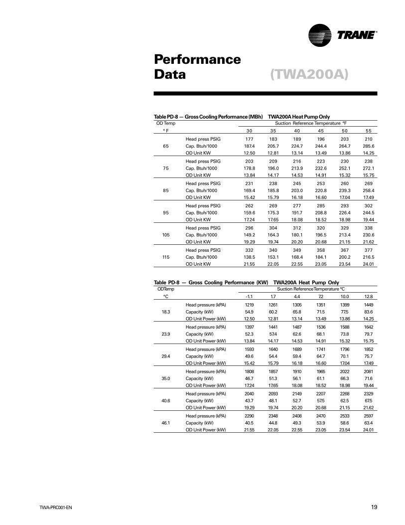
PerformanceData (TWA200A)
Table PD-8 — Gross Cooling Performance (MBh) TWA200A Heat Pump Only
OD Temp Suction Reference Temperature °F
° F 30 35 40 45 50 55
Head press PSIG 177 183 189 196 203 210
65 Cap. Btuh/1000 187.4 205.7 224.7 244.4 264.7 285.6OD Unit KW 12.50 12.81 13.14 13.49 13.86 14.25
Head press PSIG 203 209 216 223 230 238
75 Cap. Btuh/1000 178.8 196.0 213.9 232.6 252.1 272.1OD Unit KW 13.84 14.17 14.53 14.91 15.32 15.75
Head press PSIG 231 238 245 253 260 269
85 Cap. Btuh/1000 169.4 185.8 203.0 220.8 239.3 258.4OD Unit KW 15.42 15.79 16.18 16.60 17.04 17.49
Head press PSIG 262 269 277 285 293 30295 Cap. Btuh/1000 159.6 175.3 191.7 208.8 226.4 244.5
OD Unit KW 17.24 17.65 18.08 18.52 18.98 19.44
Head press PSIG 296 304 312 320 329 338105 Cap. Btuh/1000 149.2 164.3 180.1 196.5 213.4 230.6
OD Unit KW 19.29 19.74 20.20 20.68 21.15 21.62
Head press PSIG 332 340 349 358 367 377115 Cap. Btuh/1000 138.5 153.1 168.4 184.1 200.2 216.5
OD Unit KW 21.55 22.05 22.55 23.05 23.54 24.01
Table PD-8 — Gross Cooling Performance (KW) TWA200A Heat Pump Only
OD Temp Suction Reference Temperature °C
°C -1.1 1.7 4.4 7.2 10.0 12.8
Head pressure (kPA) 1219 1261 1305 1351 1399 1449
18.3 Capacity (kW) 54.9 60.2 65.8 71.5 77.5 83.6OD Unit Power (kW) 12.50 12.81 13.14 13.49 13.86 14.25
Head pressure (kPA) 1397 1441 1487 1536 1588 1642
23.9 Capacity (kW) 52.3 57.4 62.6 68.1 73.8 79.7OD Unit Power (kW) 13.84 14.17 14.53 14.91 15.32 15.75
Head pressure (kPA) 1593 1640 1689 1741 1796 185229.4 Capacity (kW) 49.6 54.4 59.4 64.7 70.1 75.7
OD Unit Power (kW) 15.42 15.79 16.18 16.60 17.04 17.49
Head pressure (kPA) 1808 1857 1910 1965 2022 208135.0 Capacity (kW) 46.7 51.3 56.1 61.1 66.3 71.6
OD Unit Power (kW) 17.24 17.65 18.08 18.52 18.98 19.44
Head pressure (kPA) 2040 2093 2149 2207 2268 232940.6 Capacity (kW) 43.7 48.1 52.7 57.5 62.5 67.5
OD Unit Power (kW) 19.29 19.74 20.20 20.68 21.15 21.62
Head pressure (kPA) 2290 2348 2408 2470 2533 2597
46.1 Capacity (kW) 40.5 44.8 49.3 53.9 58.6 63.4OD Unit Power (kW) 21.55 22.05 22.55 23.05 23.54 24.01

TWA-PRC001-EN20
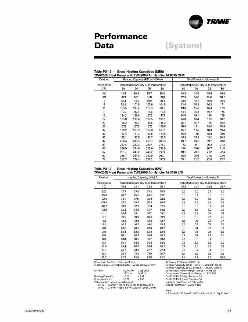
PerformanceData (System)
Outdoor Heating Capacity (KW) At Total Power in Kilowatts At
Temperature Indicated Indoor Dry Bulb Temperature Indicated Indoor Dry Bulb Temperature(°C) 15.6 21.1 23.9 26.7 15.6 21.1 23.9 26.7
-27.8 10.2 8.9 8.4 7.9 5.5 6.0 6.2 6.5-25.0 10.4 9.2 8.8 8.4 5.6 6.1 6.3 6.6-22.2 10.7 9.7 9.3 9.0 5.7 6.2 6.5 6.7-19.4 11.1 10.3 10.0 9.7 5.8 6.3 6.6 6.9-16.7 11.6 11.0 10.7 10.6 5.9 6.5 6.7 7.0-13.9 12.3 11.8 11.6 11.5 6.0 6.6 6.9 7.2-11.1 13.1 12.7 12.6 12.6 6.2 6.7 7.0 7.4-8.3 14.1 13.8 13.7 13.7 6.3 6.9 7.2 7.5-5.6 15.1 15.0 14.9 14.9 6.5 7.0 7.4 7.7-2.8 16.3 16.2 16.2 16.2 6.6 7.2 7.5 7.90.0 17.7 17.6 17.6 17.6 6.8 7.4 7.7 8.12.8 19.0 19.0 19.0 18.9 6.9 7.6 7.9 8.35.6 20.5 20.4 20.4 20.3 7.1 7.8 8.1 8.58.3 22.0 21.9 21.9 21.8 7.3 8.0 8.4 8.811.1 23.6 23.5 23.4 23.3 7.5 8.2 8.6 9.013.9 25.2 25.1 25.0 24.9 7.7 8.4 8.8 9.216.7 26.9 26.7 26.6 26.4 7.9 8.7 9.1 9.519.4 28.6 28.3 28.2 28.0 8.1 8.9 9.3 9.822.2 30.4 30.0 29.8 29.6 8.4 9.2 9.6 10.0
Correction Factors - Other Airflows(Table Value x Correction Factor = Value at new airflow)
Airflow 2250 CFM 2750 CFM1061 L/s 1297 L/s
Heating Capacity x 0.99 x 1.01Compressor Kw x 1.02 x 0.98
Values at ARI Rating Conditions of:70F (21.1C) and 47/43F (8.3/6.1C)(High Temp.Cond.)70F (21.1C) and 17/15F (-8.3/-9.4C)(Low Temp. Cond)
Airflow = 2500 cfm (1179 L/s)Heating Capacity (High Temp.) = 75,000 (21.82)Heating Capacity (Low Temp.) = 47,000 (13.84)Compressor Power (High Temp) = 5.41 kWCompressor Power (Low Temp) = 4.55 kWCoeff. Of Perf. (High Temp) = 3.2Coeff. Of Perf. (Low Temp) = 2.3Outdoor Fan Power = 550 wattsIndoor Fan Power = 800 watts
Note:1. Rated with 25 feet of 1-3/8" suction and 1/2" liquid line.
Outdoor Heating Capacity (BTUH/1000) At Total Power in Kilowatts At
Temperature Indicated Indoor Dry Bulb Temperature Indicated Indoor Dry Bulb Temperature(°F) 60 70 75 80 60 70 75 80
-18 34.9 30.4 28.5 26.9 5.5 5.6 5.7 5.8-13 35.5 31.5 30.0 28.6 5.5 5.6 5.7 5.9-8 36.5 33.1 31.8 30.6 5.4 5.6 5.8 5.9-3 37.9 35.0 34.0 33.2 5.4 5.6 5.8 6.02 39.7 37.5 36.7 36.1 5.4 5.7 5.9 6.17 42.0 40.3 39.7 39.3 5.4 5.7 6.0 6.212 44.8 43.5 43.1 42.9 5.5 5.8 6.1 6.317 48.0 47.1 46.9 46.8 5.5 5.9 6.2 6.522 51.7 51.1 51.0 50.9 5.6 6.0 6.3 6.627 55.8 55.4 55.3 55.3 5.7 6.2 6.4 6.832 60.3 60.1 60.0 60.0 5.8 6.3 6.6 6.937 65.0 64.8 64.7 64.7 5.9 6.5 6.8 7.142 69.9 69.7 69.6 69.5 6.0 6.6 6.9 7.347 75.1 74.8 74.7 74.5 6.2 6.8 7.1 7.552 80.6 80.2 79.9 79.6 6.3 7.0 7.3 7.657 86.2 85.6 85.3 84.9 6.5 7.1 7.5 7.862 92.0 91.2 90.8 90.2 6.7 7.3 7.7 8.067 97.8 96.8 96.2 95.6 6.9 7.5 7.9 8.272 103.7 102.5 101.9 101.2 7.1 7.7 8.1 8.4
Table PD-9 — Gross Heating Capacities (MBh)TWA075A Heat Pump with TWE075A Air Handler At 2500 CFM
Table PD-9 — Gross Heating Capacities (KW) TWA075A Heat Pump with TWE075A Air Handler At 1180 L/S

21TWA-PRC001-EN
PerformanceData (System)
Outdoor Heating Capacity (KW) At Total Power in Kilowatts At
Temperature Indicated Indoor Dry Bulb Temperature Indicated Indoor Dry Bulb Temperature(°C) 15.6 21.1 23.9 26.7 15.6 21.1 23.9 26.7
-27.8 6.4 11.6 12.6 13.1 5.5 6.0 6.2 6.5-25.0 9.8 12.8 13.5 13.9 5.6 6.1 6.3 6.6-22.2 11.9 13.9 14.4 14.7 5.7 6.2 6.5 6.7-19.4 13.7 15.1 15.4 15.6 5.8 6.3 6.6 6.9-16.7 15.3 16.3 16.6 16.7 5.9 6.5 6.7 7.0-13.9 16.9 17.6 17.8 17.8 6.0 6.6 6.9 7.2-11.1 18.5 19.0 19.1 19.1 6.2 6.7 7.0 7.4-8.3 20.2 20.4 20.5 20.4 6.3 6.9 7.2 7.5-5.6 21.9 22.0 22.0 21.9 6.5 7.0 7.4 7.7-2.8 23.7 23.7 23.6 23.5 6.6 7.2 7.5 7.90.0 25.6 25.4 25.3 25.2 6.8 7.4 7.7 8.12.8 27.4 27.2 27.1 27.0 6.9 7.6 7.9 8.35.6 29.3 29.1 29.0 28.8 7.1 7.8 8.1 8.58.3 31.3 31.0 30.9 30.8 7.3 8.0 8.4 8.811.1 33.5 33.1 33.0 32.9 7.5 8.2 8.6 9.013.9 35.7 35.3 35.2 35.0 7.7 8.4 8.8 9.216.7 38.0 37.6 37.4 37.3 7.9 8.7 9.1 9.519.4 40.3 39.9 39.7 39.6 8.1 8.9 9.3 9.822.2 42.7 42.3 42.1 41.9 8.4 9.2 9.6 10.0
Correction Factors - Other Airflows(Table Value x Correction Factor = Value at new airflow)
Airflow 3000 CFM 3675 CFM1416 L/s 1734 L/s
Heating Capacity x 0.99 x 1.01Compressor Kw x 1.02 x 0.98
Values at ARI Rating Conditions of:70F (21.1C) and 47/43F (8.3/6.1C)(High Temp.Cond.)70F (21.1C) and 17/15F (-8.3/-9.4C)(Low Temp. Cond)
Airflow = 3325 cfm (1569 L/s)Heating Capacity (High Temp.) = 106,000 (31.05)Heating Capacity (Low Temp.) = 69,000 (20.29)Compressor Power (High Temp) = 7.61 kWCompressor Power (Low Temp) = 6.38 kWCoeff. Of Perf. (High Temp) = 3.30Coeff. Of Perf. (Low Temp) = 2.4Outdoor Fan Power = 644 wattsIndoor Fan Power = 1,170 watts
Note:1. Rated with 25 feet of 1-3/8" suction and 1/2" liquid line.
Table PD-10 — Gross Heating Capacities (KW) TWA100A Heat Pump with TWE100A Air Handler At 1570 L/S
Outdoor Heating Capacity (BTUH/1000) At Total Power in Kilowatts At
Temperature Indicated Indoor Dry Bulb Temperature Indicated Indoor Dry Bulb Temperature(°F) 60 70 75 80 60 70 75 80
-18 21.9 39.6 43.0 44.8 5.6 7.3 7.9 8.4-13 33.4 43.6 46.0 47.3 6.2 7.5 8.0 8.5-8 40.8 47.5 49.2 50.2 6.6 7.6 8.1 8.6-3 46.7 51.5 52.8 53.4 6.8 7.8 8.2 8.72 52.3 55.7 56.5 57.0 7.0 7.9 8.4 8.87 57.7 60.1 60.6 60.8 7.2 8.1 8.5 8.912 63.2 64.8 65.1 65.1 7.4 8.2 8.6 9.117 68.9 69.8 69.9 69.8 7.5 8.4 8.8 9.222 74.8 75.1 75.1 74.9 7.7 8.5 9.0 9.427 80.9 80.8 80.6 80.3 7.9 8.7 9.1 9.632 87.3 86.8 86.5 86.2 8.0 8.9 9.4 9.837 93.6 92.9 92.6 92.2 8.2 9.1 9.6 10.142 100.2 99.3 98.9 98.5 8.4 9.3 9.8 10.347 107.1 106.0 105.6 105.2 8.6 9.5 10.1 10.652 114.4 113.2 112.7 112.3 8.8 9.8 10.3 10.957 121.9 120.6 120.1 119.7 9.1 10.1 10.6 11.262 129.7 128.3 127.8 127.3 9.3 10.4 10.9 11.567 137.7 136.2 135.6 135.1 9.6 10.7 11.2 11.972 145.9 144.3 143.7 143.2 9.9 11.0 11.6 12.2
Table PD-10 — Gross Heating Capacities (MBh)TWA100A Heat Pump with TWE100A Air Handler At 3325 CFM

TWA-PRC001-EN22
PerformanceData (System)
Table PD-11 — Gross Heating Capacities (KW)TWA155B Heat Pump with TWE155B Air Handler At 2360 L/S
Outdoor Heating Capacity (BTUH/1000) At Total Power in Kilowatts At
Temperature Indicated Indoor Dry Bulb Temperature Indicated Indoor Dry Bulb Temperature(°F) 60 70 75 80 60 70 75 80
-18 69.7 60.9 57.2 54.0 11.1 11.4 11.5 11.8-13 71.1 63.2 60.2 57.4 11.0 11.3 11.6 11.8-8 73.1 66.4 63.9 61.6 11.0 11.4 11.6 12.0-3 76.0 70.4 68.4 66.8 10.9 11.4 11.7 12.12 79.8 75.4 73.9 72.7 10.9 11.5 11.9 12.37 84.5 81.1 80.0 79.3 11.0 11.6 12.1 12.612 90.2 87.7 87.0 86.6 11.1 11.8 12.3 12.817 96.7 95.1 94.6 94.4 11.2 12.0 12.5 13.122 104.2 103.2 102.9 102.8 11.3 12.2 12.8 13.427 112.6 111.9 111.8 111.8 11.5 12.5 13.1 13.732 121.8 121.4 121.3 121.3 11.7 12.8 13.4 14.137 131.3 131.0 130.8 130.7 12.0 13.1 13.8 14.442 141.4 140.9 140.7 140.5 12.3 13.4 14.1 14.847 151.9 151.3 151.0 150.6 12.6 13.8 14.5 15.252 163.0 162.2 161.6 161.0 12.9 14.1 14.8 15.657 174.4 173.3 172.5 171.7 13.2 14.5 15.2 15.962 186.2 184.6 183.6 182.6 13.6 14.9 15.6 16.367 198.0 196.0 194.8 193.5 14.0 15.3 16.0 16.772 210.0 207.6 206.2 204.8 14.4 15.7 16.4 17.1
Table PD-11 — Gross Heating Capacities (MBh)TWA155B Heat Pump with TWE155B Air Handler At 5000 CFM
Outdoor Heating Capacity (KW) At Total Power in Kilowatts At
Temperature Indicated Indoor Dry Bulb Temperature Indicated Indoor Dry Bulb Temperature(°C) 15.6 21.1 23.9 26.7 15.6 21.1 23.9 26.7
-27.8 20.4 17.8 16.8 15.8 5.5 6.0 6.2 6.5-25.0 20.8 18.5 17.6 16.8 5.6 6.1 6.3 6.6-22.2 21.4 19.4 18.7 18.0 5.7 6.2 6.5 6.7-19.4 22.3 20.6 20.0 19.6 5.8 6.3 6.6 6.9-16.7 23.4 22.1 21.6 21.3 5.9 6.5 6.7 7.0-13.9 24.7 23.8 23.4 23.2 6.0 6.6 6.9 7.2-11.1 26.4 25.7 25.5 25.3 6.2 6.7 7.0 7.4-8.3 28.3 27.8 27.7 27.6 6.3 6.9 7.2 7.5-5.6 30.5 30.2 30.1 30.1 6.5 7.0 7.4 7.7-2.8 33.0 32.8 32.7 32.7 6.6 7.2 7.5 7.90.0 35.7 35.5 35.5 35.5 6.8 7.4 7.7 8.12.8 38.5 38.3 38.3 38.3 6.9 7.6 7.9 8.35.6 41.4 41.3 41.2 41.1 7.1 7.8 8.1 8.58.3 44.5 44.3 44.2 44.1 7.3 8.0 8.4 8.811.1 47.7 47.5 47.3 47.2 7.5 8.2 8.6 9.013.9 51.1 50.7 50.5 50.3 7.7 8.4 8.8 9.216.7 54.5 54.0 53.8 53.5 7.9 8.7 9.1 9.519.4 58.0 57.4 57.0 56.7 8.1 8.9 9.3 9.822.2 61.5 60.8 60.4 60.0 8.4 9.2 9.6 10.0
Correction Factors - Other Airflows“(Table ValueCorrection Factor = Value at new airflow)Airflow 4500 CFM 5500 CFM“
2124 L/s 2596 L/s
Heating Capacity x 0.99 x 1.01Compressor Kw x 1.02 x 0.98
Values at ARI Rating Conditions of:70F (21.1C) and 47/43F (8.3/6.1C)(High Temp.Cond.)70F (21.1C) and 17/15F (-8.3/-9.4C)(Low Temp. Cond)
Airflow = 5000 cfm (2360 L/s)Heating Capacity (High Temp.) = 151,000 (44.27)Heating Capacity (Low Temp.) = 95,000 (27.67)Compressor Power (High Temp) = 10.94 kWCompressor Power (Low Temp) = 9.18 kWCoeff. Of Perf. (High Temp) = 3.2Coeff. Of Perf. (Low Temp) = 2.3Outdoor Fan Power = 1100 wattsIndoor Fan Power = 1700 watts
Note:1.Rated with 25 feet of 1-3/8"" suction and 1/2"" liquid line."
23TWA-PRC001-EN
PerformanceData (System)
Outdoor Heating Capacity (BTUH/1000) At Total Power in Kilowatts At
Temperature Indicated Indoor Dry Bulb Temperature Indicated Indoor Dry Bulb Temperature(°F) 60 70 75 80 60 70 75 80
-18 43.5 80.3 85.7 88.4 10.8 14.5 15.6 16.5-13 68.9 87.1 91.0 93.0 12.3 14.8 15.8 16.7-8 82.3 94.2 97.0 98.4 13.0 15.1 16.0 16.8-3 93.2 101.6 103.6 104.5 13.4 15.3 16.2 17.12 103.5 109.4 110.8 111.3 13.8 15.6 16.4 17.37 113.7 117.8 118.6 118.8 14.1 15.8 16.7 17.612 124.2 126.8 127.2 127.1 14.5 16.1 17.0 17.917 135.0 136.4 136.5 136.1 14.8 16.4 17.3 18.222 146.2 146.7 146.5 146.0 15.1 16.7 17.6 18.527 157.9 157.6 157.2 156.6 15.4 17.1 18.0 18.932 170.2 169.3 168.8 168.1 15.7 17.4 18.4 19.437 182.4 181.2 180.5 179.8 16.0 17.8 18.8 19.842 195.1 193.5 192.7 192.0 16.4 18.2 19.2 20.347 208.4 206.5 205.7 205.0 16.7 18.6 19.7 20.852 222.4 220.3 219.4 218.7 17.2 19.1 20.2 21.357 236.9 234.6 233.6 232.9 17.6 19.6 20.7 21.962 251.7 249.2 248.2 247.4 18.1 20.1 21.2 22.467 266.7 264.0 262.9 262.1 18.5 20.6 21.8 23.072 282.3 279.4 278.2 277.2 19.1 21.2 22.4 23.7
Table PD-12 — Gross Heating Capacities (MBh)TWA200B Heat Pump with TWE200B Air Handler At 6675 CFM
Outdoor Heating Capacity (KW) At Total Power in Kilowatts At
Temperature Indicated Indoor Dry Bulb Temperature Indicated Indoor Dry Bulb Temperature(°C) 15.6 21.1 23.9 26.7 15.6 21.1 23.9 26.7
27.8 12.7 23.5 25.1 25.9 5.5 6.0 6.2 6.5-25.0 20.2 25.5 26.6 27.2 5.6 6.1 6.3 6.6-22.2 24.1 27.6 28.4 28.8 5.7 6.2 6.5 6.7-19.4 27.3 29.7 30.3 30.6 5.8 6.3 6.6 6.9-16.7 30.3 32.0 32.4 32.6 5.9 6.5 6.7 7.0-13.9 33.3 34.5 34.7 34.8 6.0 6.6 6.9 7.2-11.1 36.4 37.1 37.2 37.2 6.2 6.7 7.0 7.4-8.3 39.5 39.9 40.0 39.9 6.3 6.9 7.2 7.5-5.6 42.8 42.9 42.9 42.7 6.5 7.0 7.4 7.7-2.8 46.2 46.2 46.0 45.9 6.6 7.2 7.5 7.90.0 49.8 49.6 49.4 49.2 6.8 7.4 7.7 8.12.8 53.4 53.0 52.8 52.6 6.9 7.6 7.9 8.35.6 57.1 56.7 56.4 56.2 7.1 7.8 8.1 8.58.3 61.0 60.5 60.2 60.0 7.3 8.0 8.4 8.811.1 65.1 64.5 64.3 64.0 7.5 8.2 8.6 9.013.9 69.4 68.7 68.4 68.2 7.7 8.4 8.8 9.216.7 73.7 73.0 72.7 72.4 7.9 8.7 9.1 9.519.4 78.1 77.3 77.0 76.7 8.1 8.9 9.3 9.822.2 82.7 81.8 81.5 81.2 8.4 9.2 9.6 10.0
Correction Factors - Other Airflows(Table Value x Correction Factor = Value at new airflow)
Airflow 6000 CFM 7325 CFM2832 L/s 3457 L/s
Heating Capacity x 0.99 x 1.01Compressor Kw x 1.02 x 0.98Values at ARI Rating Conditions of:
70F (21.1C) and 47/43F (8.3/6.1C)(High Temp.Cond.)70F (21.1C) and 17/15F (-8.3/-9.4C)(Low Temp. Cond)
Airflow = 6700 cfm (3162 L/s)Heating Capacity (High Temp.) = 206,000 (60.26)Heating Capacity (Low Temp.) = 135,000 (39.66)Compressor Power (High Temp) = 14.92 kWCompressor Power (Low Temp) = 12.62 kWCoeff. Of Perf. (High Temp) = 3.2Coeff. Of Perf. (Low Temp) = 2.4Outdoor Fan Power = 1,100 wattsIndoor Fan Power = 2,290 watts
Note:1. Rated with 25 feet of 1-3/8” suction and 1/2" liquid line."
Table PD-12 — Gross Heating Capacities (KW)TWA200B Heat Pump with TWE200B Air Handler At 3150 L/S

TWA-PRC001-EN24
PerformanceData (Air Handler)
Table PD-14 — Blower Speeds
Motor DriveTurns OpenDrive 6 5 4 3 2 1 0
Standard N/A 590 639 688 737 786 835High Static N/A 713 772 832 891 951 1009
Table PD-13 — Evaporator Fan Performance — TWE050A
External Static Pressure (Inches of Water Gauge)
.10" .20" .30" .40" .50" .60" .70" .80" .90" 1.00" 1.10"CFM RPM BHP RPM BHP RPM BHP RPM BHP RPM BHP RPM BHP RPM BHP RPM BHP RPM BHP RPM BHP RPM BHP
0.75 HP Standard Motor and Drive1400 — — — — 646 0.37 698 0.42 751 0.47 803 0.52 856 0.56 908 0.61 941 0.65 973 0.68 1006 0.711500 — — 607 0.36 661 0.40 713 0.45 764 0.50 816 0.54 867 0.59 919 0.64 952 0.67 984 0.71 — —1600 — — 625 0.38 676 0.43 727 0.48 778 0.52 828 0.57 879 0.62 930 0.67 963 0.70 995 0.74 — —1700 601 0.35 648 0.40 696 0.44 744 0.49 792 0.54 841 0.59 889 0.64 937 0.69 971 0.73 1005 0.77 — —1800 625 0.36 671 0.41 716 0.46 762 0.51 807 0.56 853 0.61 898 0.66 944 0.71 979 0.76 — — — —1900 642 0.40 687 0.45 731 0.50 776 0.55 820 0.60 865 0.66 909 0.71 951 0.75 987 0.80 — — — —2000 659 0.44 703 0.49 745 0.54 790 0.60 833 0.65 877 0.70 920 0.75 957 0.80 994 0.84 — — — —2100 674 0.48 722 0.54 770 0.60 817 0.65 857 0.70 897 0.75 936 0.80 973 0.85 1009 0.89 — — — —
1.0 HP Oversized Motor and High Static Drive
Table PD-13— Evaporator Fan Performance — TWE050A
External Static Pressure (Pascal)
25 50 75 100 125 150 174 199 224 249 274L/S RPM KW RPM KW RPM KW RPM KW RPM KW RPM KW RPM BHP RPM BHP RPM KW RPM KW RPM KW
0.56 Standard Motor and Drive661 646 0.28 698 0.31 751 0.35 803 0.39 856 0.42 908 0.45 941 0.48 973 0.51 1006 0.53 708 607 0.27 661 0.30 713 0.34 764 0.37 816 0.40 867 0.44 919 0.48 952 0.50 984 0.53 — —755 625 0.28 676 0.32 727 0.36 778 0.39 828 0.43 879 0.46 930 0.50 963 0.52 995 0.55 — —802 601 0.26 648 0.30 696 0.33 744 0.37 792 0.40 841 0.44 889 0.48 937 0.51 971 0.54 1005 0.57 — —850 625 0.27 671 0.31 716 0.34 762 0.38 807 0.42 853 0.45 898 0.49 944 0.53 979 0.57 — — — —897 642 0.30 687 0.34 731 0.37 776 0.41 820 0.45 865 0.49 909 0.53 951 0.56 987 0.60 — — — —944 659 0.33 703 0.37 745 0.40 790 0.45 833 0.48 877 0.52 920 0.56 957 0.60 994 0.67 — — — —991 674 0.36 722 0.40 770 0.45 817 0.48 857 0.52 897 0.56 936 0.60 973 0.63 1009 0.66 — — — —
0.75 KW Oversized Motor and High Static DriveNotes:1. Performance based on a wet coil and 1 inch (25.4 mm) throwaway filters.2. Tabulated brake horsepower is the motor shaft output required.3. Factory setting of motor sheave is 1.5 turns open. Adjustments are made in
0.5 turn increments.

25TWA-PRC001-EN
PerformanceData (Air Handler)
Table PD-15 — Evaporator Fan Performance TWE075A
External Static Pressure (Pascal)
25 50 75 100 125 150 174 199 224 249 274L/S RPM KW RPM KW RPM KW RPM KW RPM KW RPM KW RPM KW RPM KW RPM KW RPM KW RPM KW
944 443 0.33 489 0.37 535 0.40 581 0.44 627 0.48 673 0.51 719 0.55 765 0.59 791 0.62 818 0.661003 453 0.34 499 0.39 546 0.43 592 0.47 638 0.51 684 0.55 730 0.59 771 0.63 798 0.67 825 0.721062 463 0.37 510 0.41 556 0.45 602 0.50 649 0.54 695 0.59 742 0.63 776 0.68 804 0.72 831 0.771121 473 0.38 520 0.43 567 0.48 613 0.52 660 0.57 706 0.62 753 0.67 782 0.72 810 0.77 838 0.821180 445 0.35 489 0.40 533 0.45 578 0.50 622 0.54 667 0.60 711 0.64 756 0.69 784 0.74 813 0.80 842 0.851239 464 0.37 506 0.43 548 0.47 589 0.51 631 0.57 672 0.61 714 0.66 757 0.71 786 0.75 815 0.81 844 0.871298 484 0.40 523 0.44 562 0.49 601 0.54 640 0.58 678 0.63 717 0.68 758 0.72 787 0.77 817 0.84 847 0.901357 504 0.42 540 0.46 576 0.51 612 0.55 648 0.60 684 0.65 720 0.69 759 0.74 789 0.78 819 0.86 850 0.921416 524 0.44 557 0.48 590 0.53 624 0.57 657 0.62 690 0.66 723 0.71 760 0.75 790 0.80 821 0.87 853 0.95
Table PD-16 — Blower SpeedsMotor Drive Turns Open
Drive 6 5 4 3 2 1 0
Standard N/A 600 650 700 750 800 850Low Static N/A 428 464 499 535 571 606High Static N/A 700 750 800 850 900 950
Table PD-15 — Evaporator Fan Performance TWE075A
External Static Pressure (In. Of Water Column)
0.10 0.20 0.30 0.40 0.50 0.60 0.70 0.80 0.90 1.00 1.10CFM RPM BHP RPM BHP RPM BHP RPM BHP RPM BHP RPM BHP RPM BHP RPM BHP RPM BHP RPM BHP RPM BHP
2000 443 0.44 489 0.49 535 0.54 581 0.59 627 0.64 673 0.69 719 0.74 765 0.79 791 0.83 818 0.89 2125 453 0.46 499 0.52 546 0.57 592 0.63 638 0.68 684 0.74 730 0.79 771 0.85 798 0.90 825 0.962250 463 0.49 510 0.55 556 0.61 602 0.67 649 0.73 695 0.79 742 0.85 776 0.91 804 0.97 831 1.03 2375 473 0.51 520 0.57 567 0.64 613 0.70 660 0.77 706 0.83 753 0.90 782 0.97 810 1.03 838 1.10 2500 445 0.47 489 0.54 533 0.60 578 0.67 622 0.73 667 0.80 711 0.86 756 0.93 784 0.99 813 1.07 842 1.14 2625 464 0.50 506 0.57 548 0.63 589 0.69 631 0.76 672 0.82 714 0.88 757 0.95 786 1.01 815 1.09 844 1.172750 484 0.53 523 0.59 562 0.66 601 0.72 640 0.78 678 0.84 717 0.91 758 0.97 787 1.03 817 1.12 847 1.212875 504 0.56 540 0.62 576 0.68 612 0.74 648 0.81 684 0.87 720 0.93 759 0.99 789 1.05 819 1.15 850 1.243000 524 0.59 557 0.65 590 0.71 624 0.77 657 0.83 690 0.89 723 0.95 760 1.01 790 1.07 821 1.17 853 1.27
1.0 HP Standard Motorand Low Static Drive
1.5 HP Oversized Motorand High Static Drive
External Static Pressure (In. Of Water Column)120 1.30 1.40 1.50 1.60
CFM RPM BHP RPM BHP RPM BHP RPM BHP RPM BHP
2000 844 0.96 871 1.02 897 1.09 924 1.15 950 1.212125 852 1.03 879 1.09 906 1.16 933 1.222250 859 1.10 886 1.17 914 1.23 942 1.302375 866 1.17 894 1.24 922 1.30 950 1.372500 870 1.21 899 1.29 928 1.362625 874 1.25 903 1.33 932 1.422750 877 1.29 907 1.38 937 1.472875 880 1.33 911 1.43 942 1.523000 884 1.37 915 1.48 946 1.58
Notes:1. Performance based on a wet coil and 1 inch (25.4 mm) throwaway
filters.2. Tabulated brake horsepower is the motor shaft output required.3. Factory setting of motor sheave is 1.5 turns open. Adjustments are
made in 0.5 turn increments.
1.12 KW Oversized Motorand High Static Drive
.75 KW Standard Motorand High Static Drive
.75 KW Standard Motorand High Static Drive
1.0 HP Standard Motorand High Static Drive
External Static Pressure (Pascal)299 324 349 374 398
L/S RPM KW RPM KW RPM KW RPM KW RPM KW
944 844 0.72 871 0.76 897 0.81 924 0.86 950 0.901003 852 0.77 879 0.81 906 0.87 933 0.911062 859 0.82 886 0.87 914 0.92 942 0.971121 866 0.87 894 0.92 922 0.97 950 1.021180 870 0,90 899 0.96 928 1.011239 874 0.93 903 0.99 932 1.061298 877 0.96 907 1.03 937 1.101357 880 0.99 911 1.07 942 1.131416 884 1.02 915 1.10 946 1.18
Table PD-15 — Continued
Table PD-15— Continued
Notes:1. Performance based on a wet coil and 1 inch (25.4 mm) throwaway
filters.2. Tabulated brake horsepower is the motor shaft output required.3. Factory setting of motor sheave is 1.5 turns open. Adjustments are
made in 0.5 turn increments.
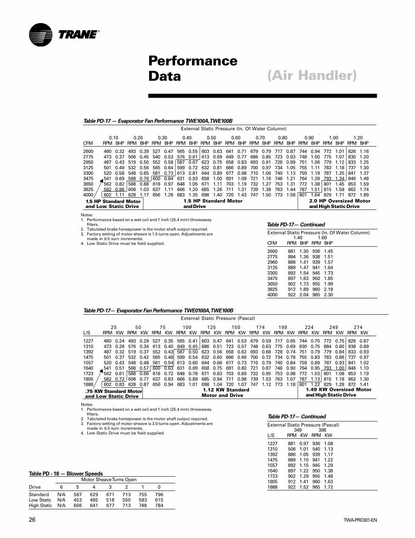
TWA-PRC001-EN26
PerformanceData (Air Handler)
Table PD-17— Evaporator Fan Performance TWE0100A, TWE100B
External Static Pressure (Pascal)
25 50 75 100 125 150 174 199 224 249 274L/S RPM KW RPM KW RPM KW RPM KW RPM KW RPM KW RPM KW RPM KW RPM KW RPM KW RPM KW
1227 460 0.24 493 0.29 527 0.35 565 0.41 603 0.47 641 0.53 679 0.59 717 0.65 744 0.70 772 0.75 826 0.871310 473 0.28 576 0.34 613 0.40 649 0.45 686 0.51 723 0.57 748 0.63 775 0.69 830 0.75 884 0.80 938 0.891392 487 0.32 519 0.37 552 0.43 587 0.50 623 0.56 658 0.62 693 0.68 728 0.74 751 0.79 779 0.84 833 0.931475 501 0.37 532 0.42 565 0.48 599 0.54 632 0.60 666 0.66 700 0.72 734 0.78 755 0.83 783 0.88 737 0.971557 520 0.43 548 0.48 581 0.54 613 0.60 644 0.66 677 0.73 710 0.79 740 0.84 759 0.89 787 0.93 841 1.021640 541 0.51 568 0.57 600 0.63 631 0.69 658 0.75 691 0.80 721 0.87 746 0.90 764 0.95 793 1.00 846 1.101723 562 0.61 588 0.66 618 0.72 648 0.78 671 0.83 703 0.89 732 0.95 753 0.98 772 1.03 801 1.08 853 1.191805 582 0.72 608 0.77 637 0.83 666 0.89 685 0.94 711 0.98 739 1.03 763 1.07 787 1.13 815 1.18 862 1.301888 602 0.83 628 0.87 656 0.94 683 1.01 698 1.04 720 1.07 747 1.12 773 1.18 801 1.22 829 1.28 872 1.41
Table PD - 18 — Blower SpeedsMotor Sheave Turns Open
Drive 6 5 4 3 2 1 0
Standard N/A 587 629 671 713 755 796Low Static N/A 453 485 518 550 583 615High Static N/A 606 641 677 713 748 784
Table PD-17 — Evaporator Fan Performance TWE100A, TWE100B
External Static Pressure (In. Of Water Column)
0.10 0.20 0.30 0.40 0.50 0.60 0.70 0.80 0.90 1.00 1.20CFM RPM BHP RPM BHP RPM BHP RPM BHP RPM BHP RPM BHP RPM BHP RPM BHP RPM BHP RPM BHP RPM BHP
2600 460 0.32 493 0.39 527 0.47 565 0.55 603 0.63 641 0.71 679 0.79 717 0.87 744 0.94 772 1.01 826 1.162775 473 0.37 506 0.45 540 0.53 576 0.61 613 0.69 649 0.77 686 0.85 723 0.93 748 1.00 775 1.07 830 1.202950 487 0.43 519 0.50 552 0.58 587 0.67 623 0.75 658 0.83 693 0.91 728 0.99 751 1.06 779 1.12 833 1.253125 501 0.49 532 0.56 565 0.64 599 0.72 632 0.81 666 0.89 700 0.97 734 1.05 755 1.11 783 1.18 737 1.303300 520 0.58 548 0.65 581 0.73 613 0.81 644 0.89 677 0.98 710 1.06 740 1.13 759 1.19 787 1.25 841 1.373475 541 0.69 568 0.76 600 0.84 631 0.93 658 1.00 691 1.08 721 1.16 746 1.21 764 1.28 793 1.34 846 1.483650 562 0.82 588 0.88 618 0.97 648 1.05 671 1.11 703 1.19 732 1.27 753 1.31 772 1.38 801 1.45 853 1.593825 582 0.96 608 1.03 637 1.11 666 1.20 685 1.26 711 1.31 739 1.38 763 1.44 787 1.51 815 1.58 862 1.744000 602 1.11 628 1.17 656 1.26 683 1.35 698 1.40 720 1.43 747 1.50 773 1.58 801 1.64 829 1.71 872 1.89
External Static Pressure (In. Of Water Column)1.40 1.60
CFM RPM BHP RPM BHP
2600 881 1.30 936 1.452775 884 1.36 938 1.512960 886 1.41 939 1.573125 889 1.47 941 1.643300 892 1.54 945 1.733475 897 1.63 950 1.853650 902 1.73 955 1.993825 912 1.89 960 2.184000 922 2.04 965 2.30
Table PD-17— Continued
1.49 KW Oversized Motorand High Static Drive
.75 KW Standard Motorand Low Static Drive
Table PD-17— Continued
1.12 KW StandardMotor and Drive
External Static Pressure (Pascal)349 398
L/S RPM KW RPM KW
1227 881 0.97 936 1.081310 506 1.01 540 1.131392 886 1.05 939 1.171475 889 1.10 941 1.221557 892 1.15 945 1.291640 897 1.22 950 1.381723 902 1.29 955 1.481805 912 1.41 960 1.631888 922 1.52 965 1.72
1.5 HP Standard Motorand Low Static Drive
2.0 HP Oversized Motorand High Static Drive
1.5 HP Standard Motorand Drive
Notes:1. Performance based on a wet coil and 1 inch (25.4 mm) throwaway
filters.2. Tabulated brake horsepower is the motor shaft output required.3. Factory setting of motor sheave is 1.5 turns open. Adjustments are
made in 0.5 turn increments.4. Low Static Drive must be field supplied.
Notes:1. Performance based on a wet coil and 1 inch (25.4 mm) throwaway
filters.2. Tabulated brake horsepower is the motor shaft output required.3. Factory setting of motor sheave is 3.0 turns open. Adjustments are
made in 0.5 turn increments.4. Low Static Drive must be field supplied.
27TWA-PRC001-EN
PerformanceData (Air Handler)
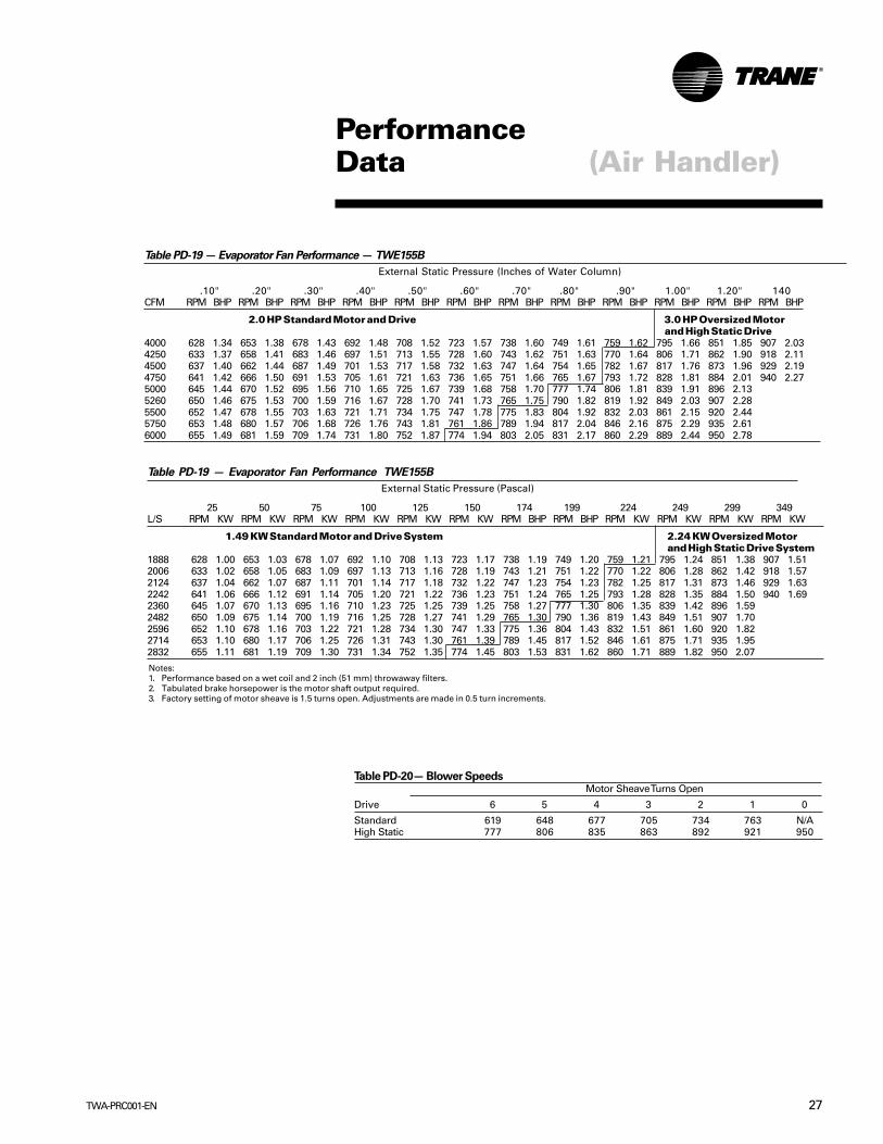
Table PD-20— Blower SpeedsMotor Sheave Turns Open
Drive 6 5 4 3 2 1 0
Standard 619 648 677 705 734 763 N/AHigh Static 777 806 835 863 892 921 950
Table PD-19 — Evaporator Fan Performance — TWE155B
External Static Pressure (Inches of Water Column)
.10" .20" .30" .40" .50" .60" .70" .80" .90" 1.00" 1.20" 140CFM RPM BHP RPM BHP RPM BHP RPM BHP RPM BHP RPM BHP RPM BHP RPM BHP RPM BHP RPM BHP RPM BHP RPM BHP
2.0 HP Standard Motor and Drive 3.0 HP Oversized Motorand High Static Drive
4000 628 1.34 653 1.38 678 1.43 692 1.48 708 1.52 723 1.57 738 1.60 749 1.61 759 1.62 795 1.66 851 1.85 907 2.034250 633 1.37 658 1.41 683 1.46 697 1.51 713 1.55 728 1.60 743 1.62 751 1.63 770 1.64 806 1.71 862 1.90 918 2.114500 637 1.40 662 1.44 687 1.49 701 1.53 717 1.58 732 1.63 747 1.64 754 1.65 782 1.67 817 1.76 873 1.96 929 2.194750 641 1.42 666 1.50 691 1.53 705 1.61 721 1.63 736 1.65 751 1.66 765 1.67 793 1.72 828 1.81 884 2.01 940 2.275000 645 1.44 670 1.52 695 1.56 710 1.65 725 1.67 739 1.68 758 1.70 777 1.74 806 1.81 839 1.91 896 2.135260 650 1.46 675 1.53 700 1.59 716 1.67 728 1.70 741 1.73 765 1.75 790 1.82 819 1.92 849 2.03 907 2.285500 652 1.47 678 1.55 703 1.63 721 1.71 734 1.75 747 1.78 775 1.83 804 1.92 832 2.03 861 2.15 920 2.445750 653 1.48 680 1.57 706 1.68 726 1.76 743 1.81 761 1.86 789 1.94 817 2.04 846 2.16 875 2.29 935 2.616000 655 1.49 681 1.59 709 1.74 731 1.80 752 1.87 774 1.94 803 2.05 831 2.17 860 2.29 889 2.44 950 2.78
Table PD-19 — Evaporator Fan Performance TWE155B
External Static Pressure (Pascal)
25 50 75 100 125 150 174 199 224 249 299 349L/S RPM KW RPM KW RPM KW RPM KW RPM KW RPM KW RPM BHP RPM BHP RPM KW RPM KW RPM KW RPM KW
1.49 KW Standard Motor and Drive System 2.24 KW Oversized Motorand High Static Drive System
1888 628 1.00 653 1.03 678 1.07 692 1.10 708 1.13 723 1.17 738 1.19 749 1.20 759 1.21 795 1.24 851 1.38 907 1.512006 633 1.02 658 1.05 683 1.09 697 1.13 713 1.16 728 1.19 743 1.21 751 1.22 770 1.22 806 1.28 862 1.42 918 1.572124 637 1.04 662 1.07 687 1.11 701 1.14 717 1.18 732 1.22 747 1.23 754 1.23 782 1.25 817 1.31 873 1.46 929 1.632242 641 1.06 666 1.12 691 1.14 705 1.20 721 1.22 736 1.23 751 1.24 765 1.25 793 1.28 828 1.35 884 1.50 940 1.692360 645 1.07 670 1.13 695 1.16 710 1.23 725 1.25 739 1.25 758 1.27 777 1.30 806 1.35 839 1.42 896 1.592482 650 1.09 675 1.14 700 1.19 716 1.25 728 1.27 741 1.29 765 1.30 790 1.36 819 1.43 849 1.51 907 1.702596 652 1.10 678 1.16 703 1.22 721 1.28 734 1.30 747 1.33 775 1.36 804 1.43 832 1.51 861 1.60 920 1.822714 653 1.10 680 1.17 706 1.25 726 1.31 743 1.30 761 1.39 789 1.45 817 1.52 846 1.61 875 1.71 935 1.952832 655 1.11 681 1.19 709 1.30 731 1.34 752 1.35 774 1.45 803 1.53 831 1.62 860 1.71 889 1.82 950 2.07
Notes:1. Performance based on a wet coil and 2 inch (51 mm) throwaway filters.2. Tabulated brake horsepower is the motor shaft output required.3. Factory setting of motor sheave is 1.5 turns open. Adjustments are made in 0.5 turn increments.

TWA-PRC001-EN28
PerformanceData (Air Handler)
Notes:1. Performance based on a wet coil and 2 inch (51 mm) throwaway filters.2. Tabulated brake horsepower is the motor shaft output required.3. Factory setting of motor sheave is 1.5 turns open. Adjustments are made in
0.5 turn increments.
Table PD-22 — Blower SpeedsMotor Sheave Turns Open
Drive 6 5 4 3 2 1 0
Standard 706 732 758 784 811 837 863Low Static 457 478 500 521 542 563 585Field-Supplied Low Static 574 595 617 638 659 680 702High Static N/A 821 862 903 945 986 1027
Table PD-21— Evaporator Fan Performance TWE200B
External Static Pressure (In. Of Water Column)
0.10 0.20 0.30 0.40 0.50 0.60 0.70 0.80 0.90 1.00 1.20 140CFM RPM BHP RPM BHP RPM BHP RPM BHP RPM BHP RPM BHP RPM BHP RPM BHP RPM BHP RPM BHP RPM BHP RPM BHP
5200 461 0.74 503 0.91 545 1.07 587 1.03 619 1.17 685 1.40 723 1.59 750 1.74 777 1.89 851 2.19 898 2.395525 479 0.88 521 1.04 563 1.21 605 1.21 640 1.35 701 1.58 739 1.77 766 1.92 793 2.07 859 2.37 906 2.605850 497 1.01 539 1.18 581 1.34 623 1.39 661 1.53 717 1.76 755 1.95 782 2.10 809 2.25 868 2.55 915 2.81 6175 473 0.99 515 1.15 557 1.31 599 1.48 641 1.57 682 1.71 732 1.94 769 2.12 796 2.27 823 2.43 877 2.73 924 3.026500 492 1.12 534 1.28 576 1.45 618 1.61 660 1.75 702 1.90 748 2.12 784 2.30 811 2.45 838 2.60 886 2.91 933 3.226825 510 1.25 552 1.42 594 1.59 636 1.75 678 1.91 723 2.10 763 2.30 794 2.47 820 2.62 846 2.77 894 3.09 941 3.427150 528 1.38 570 1.56 612 1.73 654 1.90 697 2.07 744 2.30 779 2.49 804 2.64 830 2.78 855 2.94 903 3.26 950 3.627475 550 1.61 594 1.77 640 1.92 683 2.08 721 2.29 760 2.50 790 2.67 815 2.81 840 2.96 865 3.11 914 3.47 959 3.857800 572 1.83 618 1.97 668 2.10 712 2.27 746 2.52 776 2.69 802 2.84 826 2.99 851 3.13 876 3.27 926 3.67 969 4.083.0 StandardMotor andLow Static Drive
5 HP Oversized Motorand High Static Drive
External Static Pressure (In. Of Water Column)1.60 1.80
CFM RPM BHP RPM BHP
5200 944 2.75 989 3.125525 952 2.96 997 3.335850 961 3.17 1006 3.545175 970 3.38 1015 3.758500 978 3.59 1023 3.968825 986 3.807150 994 4.017475 1003 4.257800 1012 4.50
Table PD-21— Continued
3.0 HP StandardMotor and Field-SuppliedLow Static Drive
Table PD-21— Evaporator Fan Performance TWE200B
External Static Pressure (Pascal)
25 50 75 100 125 150 174 199 224 249 299 349CFM RPM BHP RPM BHP RPM BHP RPM BHP RPM BHP RPM BHP RPM BHP RPM BHP RPM BHP RPM BHP RPM BHP RPM BHP
2454 461 0.55 503 0.68 545 0.80 587 0.77 619 0.87 685 1.04 723 1.19 750 1.30 777 1.41 851 1.63 898 1.782608 479 0.66 521 0.78 563 0.90 605 0.90 640 1.01 701 1.18 739 1.32 766 1.43 793 1.54 859 1.77 906 1.942761 497 0.75 539 0.88 581 1.00 623 1.04 661 1.14 717 1.31 755 1.45 782 1.57 809 1.68 868 1.90 915 2.102914 473 0.74 515 0.86 557 0.98 599 1.10 641 1.17 682 1.28 732 1.45 769 1.58 796 1.69 823 1.81 877 2.04 924 2.523068 492 0.84 534 0.95 576 1.08 618 1.20 660 1.30 702 1.42 748 1.58 784 1.72 811 1.83 838 1.94 886 2.17 933 2.403221 510 0.93 552 1.06 594 1.19 636 1.30 678 1.42 723 1.57 763 1.72 794 1.84 820 1.95 846 2.07 894 2.30 941 2.553374 528 1.03 570 1.16 612 1.29 654 1.42 697 1.54 744 1.72 779 1.86 804 1.97 830 2.07 855 2.19 903 2.43 950 2.703528 550 1.20 594 1.32 640 1.43 683 1.55 721 1.71 760 1.87 790 1.99 815 2.10 840 2.21 865 2.32 914 2.59 959 2.873681 572 1.36 618 1.47 668 1.57 712 1.69 746 1.88 776 2.01 802 2.12 826 2.23 851 2.33 876 2.44 926 2.74 969 3.04Standard Motor3.0 HP andLow Static Drive
5 HP Oversized Motorand High Static Drive
External Static Pressure (Pascal)398 448
CFM RPM BHP RPM BHP
2454 944 2.05 989 2.332608 952 2.21 997 2.482761 961 2.36 1006 2.642914 970 2.52 1015 2.803068 978 2.68 1023 2.953221 941 2.55 986 2.833374 994 2.993528 1003 3.173681 1012 3.36
Table PD-21— Continued
3.0 HP StandardMotor and Field-SuppliedLow Static Drive
Notes:1. Performance based on a wet coil and 2 inch (51 mm) throwaway filters.2. Tabulated brake horsepower is the motor shaft output required.3. Factory setting of motor sheave is 1.5 turns open. Adjustments are made in 0.5 turn
increments.
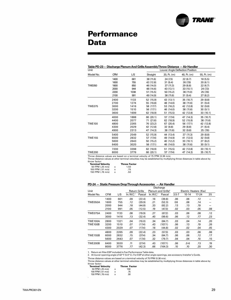
29TWA-PRC001-EN
PerformanceData
Table PD-23— Discharge Plenum And Grille Assembly Throw Distance — Air HandlerUnit Louver Angle Deflection Position
Model No. CFM L/S Straight 20, Ft. (m) 40, Ft. (m) 55, Ft. (m)
1400 661 38 (11.6) 24 (7.3) 22 (6.7) 18 (5.5)1600 755 42 (12.8) 31 (9.4) 26 (7.9) 20 (6.1)
TWE050 1800 850 46 (14.0) 37 (11.3) 29 (8.8) 22 (6.7)2000 944 48 (14.6) 43 (13.1) 33 (10.1) 24 (7.3)2200 1038 51 (15.5) 50 (15.2) 36 (11.0) 25 (7.6)2100 991 49 (14.9) 38 (11.6) 31 (9.4) 27 (8.2)
2400 1133 52 (15.9) 43 (13.1) 35 (10.7) 29 (8.8)2700 1274 55 (16.8) 48 (14.6) 38 (11.6) 31 (9.4)
TWE075 3000 1416 58 (17.7) 53 (16.2) 42 (12.8) 32 (9.8)3200 1510 56 (17.1) 46 (14.0) 38 (11.6) 30 (9.1)3600 1699 62 (18.9) 51 (15.5) 42 (12.8) 33 (10.1)
4000 1888 66 (20.1) 57 (17.4) 47 (14.3) 35 (10.7)4400 2077 71 (21.6) 62 (18.9) 52 (15.9) 38 (11.6)
TWE100 4800 2265 76 (23.2) 67 (20.4) 56 (17.1) 42 (12.8)4300 2029 42 (12.8) 32 (9.8) 29 (8.8) 21 (6.4)4900 2313 47 (14.3) 38 (11.6) 32 (9.8) 25 (7.6)
5400 2549 52 (15.9) 44 (13.4) 37 (11.3) 29 (8.8)TWE155 6000 2832 57 (17.4) 49 (14.9) 41 (12.5) 32 (9.8)
5600 2643 50 (15.2) 40 (12.2) 33 (10.1) 27 (8.2)6400 3020 56 (17.1) 46 (14.0) 38 (11.6) 30 (9.1)
7200 3398 62 (18.9) 51 (15.5) 42 (12.8) 33 (10.1)TWE200 8000 3776 66 (20.1) 57 (17.4) 47 (14.3) 35 (10.7)Throw distance values are based on a terminal velocity of 75 FPM (0.38 m/s).Throw distance values at other terminal velocities may be established by multiplying throw distances in table above bythrow factor:
Terminal Velocity Throw Factor50 FPM (.25 m/s) x 1.50
100 FPM (.51 m/s) x .75150 FPM (.76 m/s) x .50
PD-24 — Static Pressure Drop Through Accessories — Air HandlerDischarge
Unit Return Grille Plenum and Grille2 Electric Heaters (Kw)Model No. CFM L/S In. W.C.1 Pascal In. W.C.1 Pascal 3.5-7 10-14 17-24 35
1400 661 .09 (22.4) .16 (39.8) .06 .06 .12 —TWE050A 1600 755 .12 (29.9) .21 (52.3) 08 .08 .14 —
2000 944 .18 (44.8) .33 (82.2) .13 .13 .19 —2100 991 .05 (12.5) .19 (47.3) .02 .03 .05 .08
TWE075A 2400 1133 .08 (19.9) .27 (67.2) .03 .06 .08 .123000 1416 .13 (32.4) .40 (99.6) .06 .12 .17 .23
TWE100A 2800 1321 .04 (10.0) .34 (84.7) .03 .04 .14 .20TWE100B 3200 1510 .07 (17.4) .43 (107.1) .06 .13 .19 .26
4300 2029 .07 (17.4) .18 (44.8) .02 .02 .04 .05
4800 2265 .09 (22.4) .23 (57.3) .03 .03 .06 .08TWE155B 6000 2832 .15 (37.4) .34 (84.7) .06 .06 .12 .17
5600 2643 .07 (17.4) .32 (79.7) .04 .04 .10 .15
TWE200B 6400 3020 .11 (27.4) .43 (107.1) .06 .0-6 .13 .198000 3776 .17 (42.3) .66 (164.3) .10 .10 .20 .30
1. Return air filter ESP included in Fan Performance Table data.2. At louver opening angle of 42° F (5.5° C). For ESP at other angle openings, see accessory Installer’s Guide.
Throw distance values are based on a terminal velocity of 75 FPM (0.38 m/s).Throw distance values at other terminal velocities may be established by multiplying throw distances in table above bythrow factor:
Terminal Velocity Throw Factor50 FPM (.25 m/s) x 1.50
100 FPM (.51 m/s) x .75150 FPM (.76 m/s) x .50
.

TWA-PRC001-EN30
PerformanceData
Table PD-25 — Auxiliary Electric Heat Capacity — Air HandlerNo. Stage 1 Stage 2 Total
Unit Total of KW Btuh KW KW Btuh KW Btuh KWModel No. KW Stages Input Output Output Input Output Output Output Output
TWE050, 075,100 3.47 1 3.47 11,851 3.47 — — — 11,851 3.476.92 1 9.92 23,606 6.92 — — — 23,606 6.92
10.39 1 10.39 35,457 10.39 — — — 35,457 10.3917.31 2 10.39 35,457 10.39 6.92 23,606 6.92 59,063 17.31
TWE075, 100A, 100 24.22 2 13.83 47,213 13.83 10.39 35,457 10.39 82,670 24.22
TWE155, 200 6.94 1 6.94 23,701 6.94 — — — 23,701 6.9413.83 1 13.83 47,213 13.83 — — — 47,213 13.8320.78 2 13.83 47,213 13.83 6.94 23,701 6.94 70,915 20.7834,62 2 20.78 70,915 20.78 13.84 47,213 13.89 118,128 34.61
*Heaters are rated at 400v. For other than rated voltage,
Capacity = Voltage 2 x Rated Capacity and KW = Voltage 2 x Rated KW.(Rated Voltage ) ( Rated Voltage )
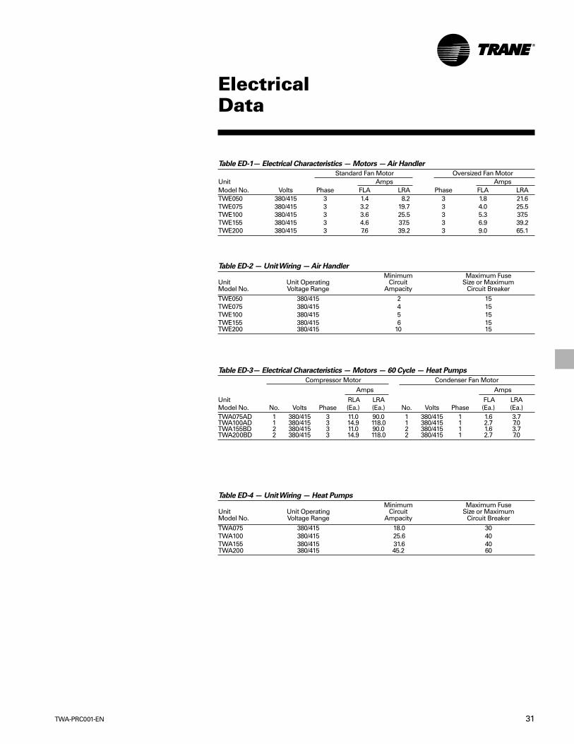
31TWA-PRC001-EN
ElectricalData
Table ED-1— Electrical Characteristics — Motors — Air Handler
Standard Fan Motor Oversized Fan MotorUnit Amps AmpsModel No. Volts Phase FLA LRA Phase FLA LRATWE050 380/415 3 1.4 8.2 3 1.8 21.6TWE075 380/415 3 3.2 19.7 3 4.0 25.5TWE100 380/415 3 3.6 25.5 3 5.3 37.5TWE155 380/415 3 4.6 37.5 3 6.9 39.2TWE200 380/415 3 7.6 39.2 3 9.0 65.1
Table ED-2 — Unit Wiring — Air Handler
Minimum Maximum FuseUnit Unit Operating Circuit Size or MaximumModel No. Voltage Range Ampacity Circuit BreakerTWE050 380/415 2 15TWE075 380/415 4 15TWE100 380/415 5 15TWE155 380/415 6 15TWE200 380/415 10 15
Table ED-4 — Unit Wiring — Heat Pumps
Minimum Maximum FuseUnit Unit Operating Circuit Size or MaximumModel No. Voltage Range Ampacity Circuit BreakerTWA075 380/415 18.0 30TWA100 380/415 25.6 40TWA155 380/415 31.6 40TWA200 380/415 45.2 60
Table ED-3— Electrical Characteristics — Motors — 60 Cycle — Heat Pumps
Compressor Motor Condenser Fan MotorAmps Amps
Unit RLA LRA FLA LRAModel No. No. Volts Phase (Ea.) (Ea.) No. Volts Phase (Ea.) (Ea.)TWA075AD 1 380/415 3 11.0 90.0 1 380/415 1 1.6 3.7TWA100AD 1 380/415 3 14.9 118.0 1 380/415 1 2.7 7.0TWA155BD 2 380/415 3 11.0 90.0 2 380/415 1 1.6 3.7TWA200BD 2 380/415 3 14.9 118.0 2 380/415 1 2.7 7.0
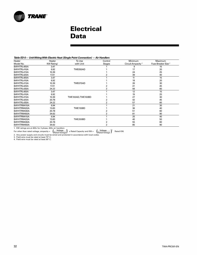
TWA-PRC001-EN32
ElectricalData
Table ED-5— Unit Wiring With Electric Heat (Single Point Connection) — Air Handlers
Heater Heater To Use Control Minimum MaximumModel No. KW Rating1 with Unit Stages Circuit Ampacity 2 Fuse Breaker Size 2
BAYHTRL405A 3.47 1 9 15BAYHTRL410A 6.92 TWE050AD 1 17 20BAYHTRL415A 10.39 1 24 25BAYHTRL425A 17.31 2 39 40BAYHTRL405A 3.47 1 11 15BAYHTRL410A 6.92 1 18 20BAYHTRL415A 10.39 TWE075AD 1 26 30BAYHTRL425A 17.31 2 41 45BAYHTRL435A 24.22 2 56 60BAYHTRL405A 3.47 1 12 15BAYHTRL410A 6.92 1 19 25BAYHTRL415A 10.39 TWE100AD, TWE100BD 1 27 30BAYHTRL425A 20.78 2 42 45BAYHTRL435A 24.22 2 57 60BAYHTRM410A 6.94 1 21 30BAYHTRM420A 13.83 TWE155BD 1 36 40BAYHTRM430A 20.78 2 51 60BAYHTRM450A 34.62 2 81 90BAYHTRM410A 6.94 1 25 40BAYHTRM420A 13.83 TWE200BD 1 40 50BAYHTRM430A 20.78 2 55 60BAYHTRM450A 34.62 2 85 901. KW ratings are at 400v for 3 phase, 400v air handlers
For other than rated voltage, ampacity = Voltage 2 x Rated Capacity and KW = Voltage 2 Rated KW.(Rated Voltage) (Rated Voltage )2. Any power supply and circuits must be wired and protected in accordance with local codes.3. Field wire must be rated at least 75° C.4. Field wire must be rated at least 90° C.
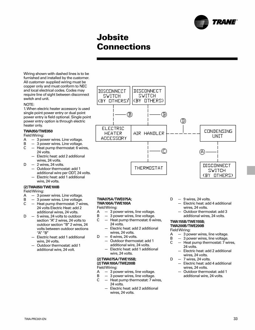
33TWA-PRC001-EN
JobsiteConnections
Wiring shown with dashed lines is to befurnished and installed by the customer.All customer- supplied wiring must becopper only and must conform to NECand local electrical codes. Codes mayrequire line of sight between disconnectswitch and unit.
NOTE:1. When electric heater accessory is usedsingle point power entry or dual pointpower entry is field optional. Single pointpower entry option is through electricheater only.
TWA050/TWE050Field Wiring:A — 3 power wires. Line voltage.B — 3 power wires. Line voltage.C — Heat pump thermostat: 6 wires,
24 volts.— Electric heat: add 2 additional
wires, 24 volts.D — 2 wires, 24 volts.
— Outdoor thermostat: add 1additional wire per ODT, 24 volts.
— Electric heat: add 1 additionalwire, 24 volts.
(2) TWA050/TWE100BField Wiring:A — 3 power wires. Line voltage.B — 3 power wires. Line voltage.C — Heat pump thermostat: 7 wires,
24 volts Electric Heat: add 2additional wires, 24 volts.
D — 5 wires, 24 volts to outdoorsection ‘’A’’ 2 wires, 24 volts tooutdoor section ‘’B’’ 2 wires, 24volts between outdoor sections‘’A’’ ‘’B’’
— Electric heat: add 1 additionalwire, 24 volts.
— Outdoor thermostat: add 1additional wire, 24 volt.
TWA075A/TWE075A;TWA100A/TWE100AField Wiring:A — 3 power wires, line voltage.B — 3 power wires, line voltage.C — Heat pump thermostat: 6 wires,
24 volts.— Electric heat: add 2 additional
wires, 24 volts.D — 6 wires, 24 volts.
— Outdoor thermostat: add 1additional wire, 24 volts.
— Electric heat: add 1 additionalwire, 24 volts.
(2) TWA075A/TWE155B;(2) TWA100A/TWE200BField Wiring:A — 3 power wires, line voltage.B — 3 power wires, line voltage.C — Heat pump thermostat: 7 wires,
24 volts.— Electric heat: add 2 additional
wires, 24 volts.
D — 9 wires, 24 volts.— Electric heat: add 4 additional
wires, 24 volts.— Outdoor thermostat: add 3
additional wires, 24 volts.
TWA155B/TWE155B;TWA200B/TWE200BField Wiring:A — 3 power wires, line voltage.B — 3 power wires, line voltage.C — Heat pump thermostat: 7 wires,
24 volts.— Electric heat: add 2 additional
wires, 24 volts.D — 7 wires, 24 volts.
— Electric heat: add 4 additionalwires, 24 volts.
— Outdoor thermostat: add 1additional wire, 24 volts.

TWA-PRC001-EN34
TypicalWiring (Heat Pump)
Heat Pump — Single Compressor
Typical unit wiring diagram. For specificwiring, see individual Service Facts.

35TWA-PRC001-EN
TypicalWiring (Heat Pump)

TWA-PRC001-EN36
Heat Pump — Dual Compressors
Typical unit wiring diagram. For specificwiring, see individual Service Facts.
(Heat Pump)TypicalWiring

37TWA-PRC001-EN
TypicalWiring (Heat Pump)
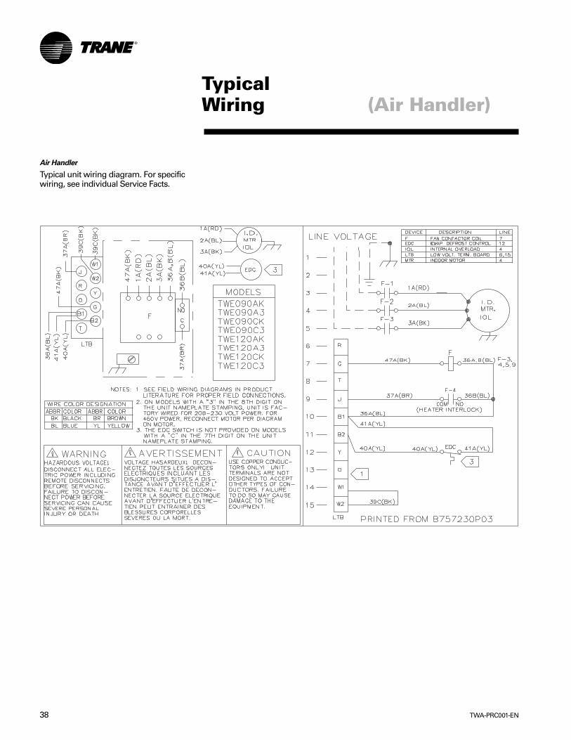
TWA-PRC001-EN38
TypicalWiring (Air Handler)
Air Handler
Typical unit wiring diagram. For specificwiring, see individual Service Facts.

39TWA-PRC001-EN
(Heat Pump)DimensionalData
Figure DD-1 — TWA075 Heat Pump
All dimensions are in inches and millimeters.
Note 1MINIMUM CLEARANCE FOR PROPEROPERATION IS 36 INCHES (914 MM)FROM WALLS, SHRUBBERY, PRIVACYFENCES, ETC. MINIMUM CLEARANCEBETWEEN ADJACENT UNITS IS 72INCHES (1828 MM)

TWA-PRC001-EN40
DimensionalData (Heat Pump)
Figure DD-2 — 10 Ton TWA100A Heat Pump
All dimensions are in inches and millimeters.
Note 1MINIMUM CLEARANCE FOR PROPEROPERATION IS 36 INCHES (914 MM)FROM WALLS, SHRUBBERY, PRIVACYFENCES, ETC. MINIMUM CLEARANCEBETWEEN ADJACENT UNITS IS 72INCHES (1828 MM)
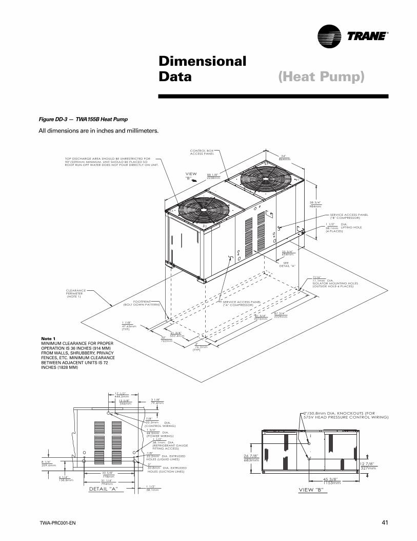
41TWA-PRC001-EN
DimensionalData (Heat Pump)
Figure DD-3 — TWA155B Heat Pump
All dimensions are in inches and millimeters.
Note 1MINIMUM CLEARANCE FOR PROPEROPERATION IS 36 INCHES (914 MM)FROM WALLS, SHRUBBERY, PRIVACYFENCES, ETC. MINIMUM CLEARANCEBETWEEN ADJACENT UNITS IS 72INCHES (1828 MM)

TWA-PRC001-EN42
(Heat Pump)DimensionalData
Figure DD-4 — TWA200B Heat Pump
All dimensions are in inches and millimeters.
Note 1MINIMUM CLEARANCE FOR PROPEROPERATION IS 36 INCHES (914 MM)FROM WALLS, SHRUBBERY, PRIVACYFENCES, ETC. MINIMUM CLEARANCEBETWEEN ADJACENT UNITS IS 72INCHES (1828 MM)

43TWA-PRC001-EN
(Air Handler)DimensionalData
Figure DD-5 — TWE050A Air Handlers
All dimensions are in inches and millimeters.
Notes:1. Length, Width, and Height Dimensions do not include 1/2”
(12.7mm) access panel depth.2. Removable drain pan and attached drain connection may be
installed on either end of unit in either the vertical or horizontalconfiguration. Plastic drain pan access plate on the end of unitopposite drain connection must be removed to slide drain pan outfor cleaning. Access plate must be reinstalled after sliding drainpan back into unit.
3. If periodic drain pan cleaning is required, allow room for partialremoval of pan on drain connection end of unit.

TWA-PRC001-EN44
(Air Handler)DimensionalData
Figure DD-6 — TWE075A Air Handler
All dimensions are in inches and millimeters.
Notes:1. Length, Width, and Height Dimensions do not include 1/2”
(12.7mm) access panel depth.2. Removable drain pan and attached drain connection may be
installed on either end of unit in either the vertical or horizontalconfiguration. Plastic drain pan access plate on the end of unitopposite drain connection must be removed to slide drain pan outfor cleaning. Access plate must be reinstalled after sliding drainpan back into unit.
3. If periodic drain pan cleaning is required, allow room for partialremoval of pan on drain connection end of unit.
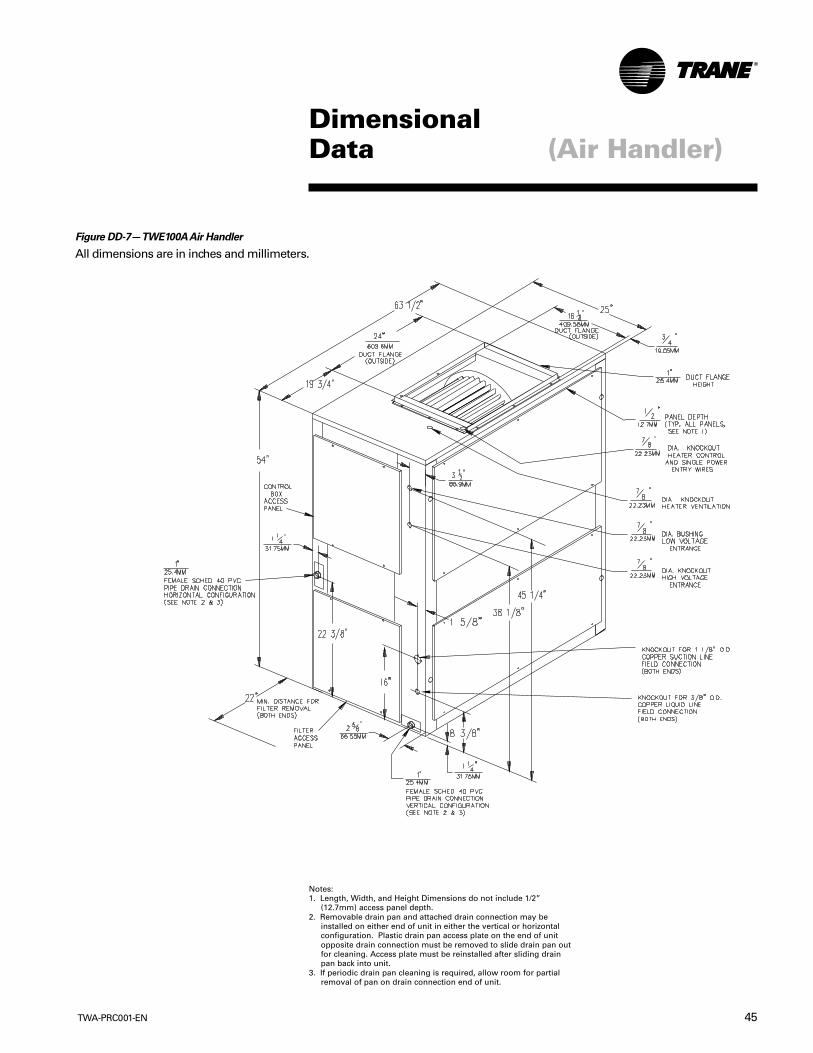
45TWA-PRC001-EN
Notes:1. Length, Width, and Height Dimensions do not include 1/2”
(12.7mm) access panel depth.2. Removable drain pan and attached drain connection may be
installed on either end of unit in either the vertical or horizontalconfiguration. Plastic drain pan access plate on the end of unitopposite drain connection must be removed to slide drain pan outfor cleaning. Access plate must be reinstalled after sliding drainpan back into unit.
3. If periodic drain pan cleaning is required, allow room for partialremoval of pan on drain connection end of unit.
Figure DD-7— TWE100A Air Handler
All dimensions are in inches and millimeters.
DimensionalData (Air Handler)
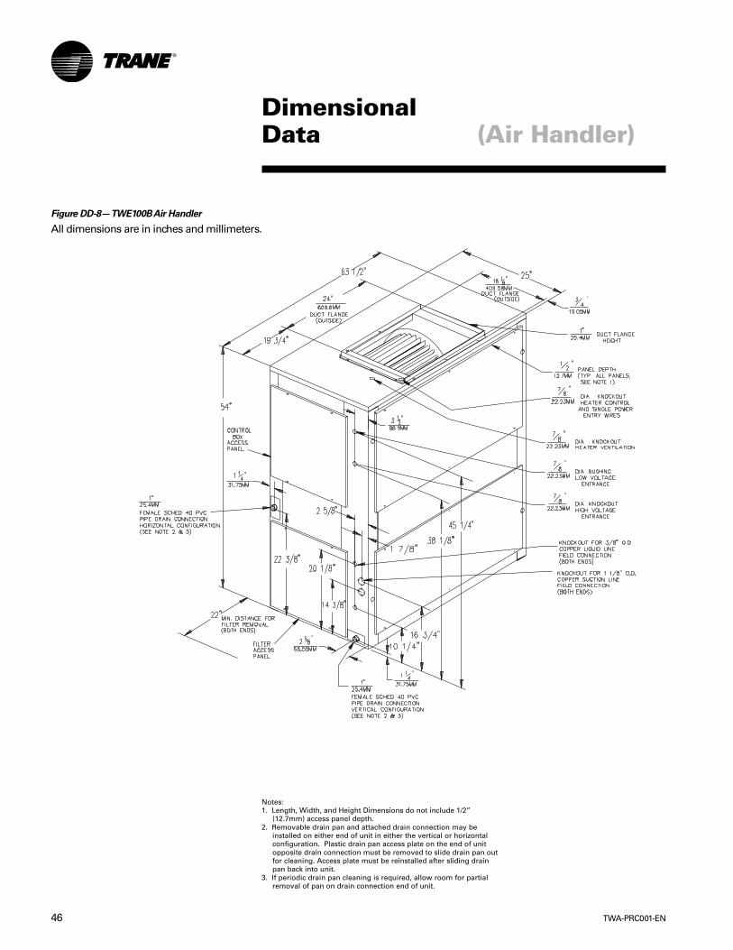
TWA-PRC001-EN46
DimensionalData (Air Handler)
Notes:1. Length, Width, and Height Dimensions do not include 1/2”
(12.7mm) access panel depth.2. Removable drain pan and attached drain connection may be
installed on either end of unit in either the vertical or horizontalconfiguration. Plastic drain pan access plate on the end of unitopposite drain connection must be removed to slide drain pan outfor cleaning. Access plate must be reinstalled after sliding drainpan back into unit.
3. If periodic drain pan cleaning is required, allow room for partialremoval of pan on drain connection end of unit.
Figure DD-8— TWE100B Air Handler
All dimensions are in inches and millimeters.

47TWA-PRC001-EN
DimensionalData (Air Handlers)
Table DD-1 — Air Handler Dimensions — in. (mm)Model No. AA AB AC AD AE AF AJ AK ALTWE050A 35 5/8 12 1/16 1 5/8 32 1/4 2 15/16 32 1/4 7 13/16 12 3/8 34 9/16
(905) (306.4) (41.3) (819.2) (74.6) (819.2) (198.4) (314.3) (878)TWE075A 45 1/8 16 1 11/16 41 15/16 6 5/8 41 3/4 7 16 36 7/8
(1146.2) (406.4) (42.9) (1065.2) (168.3) (1060.5) (177.8) (406.4) (936.6)TWE100A 61 1/8 16 1 11/16 57 15/16 6 5/8 57 13/16 7 16 36 7/8
(1552.6) (406.4) (42.9) (1471.6) (168.3) (1468.4) (177.8) (406.4) (936.6)TWE100B 61 1/8 16 1 11/16 57 15/16 6 5/8 57 13/16 7 16 36 7/8
(1552.6) (406.4) (42.9) (1471.6) (168.3) (1468.4) (177.8) (406.4) (936.6)
Figure DD-9— TWE050A, 075A, 100A and TWE100B Air Handler
All dimensions are in inches and millimeters.
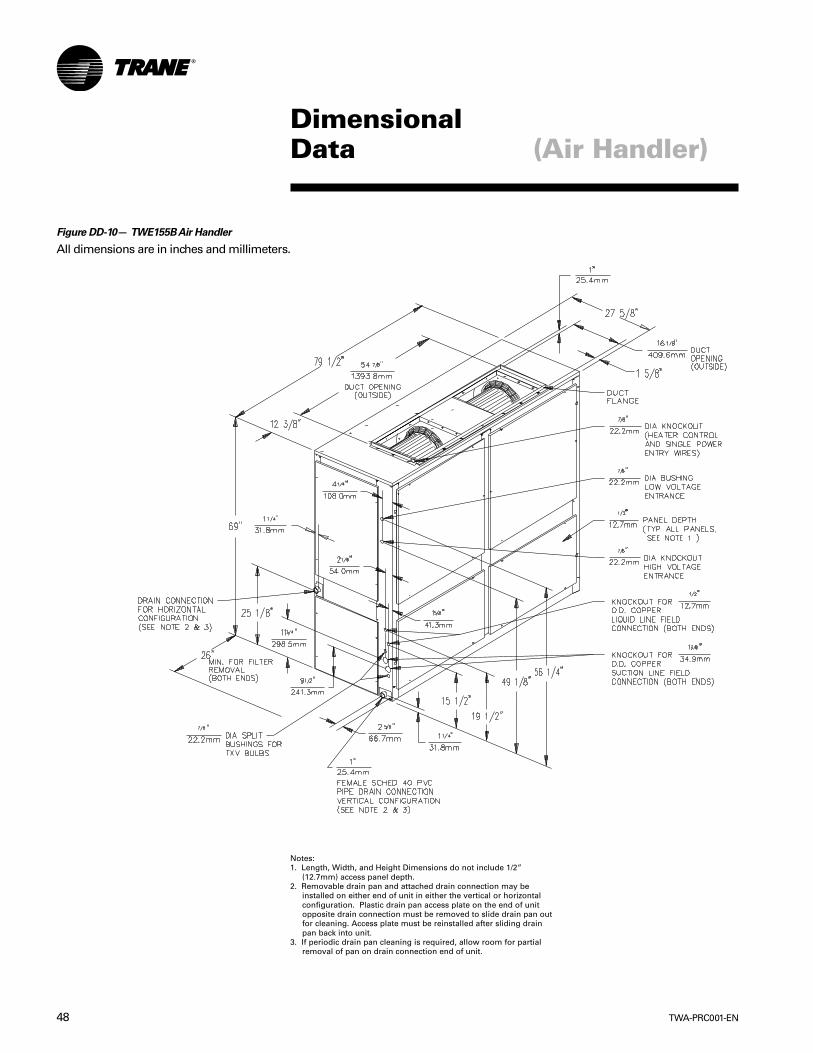
TWA-PRC001-EN48
DimensionalData
Figure DD-10— TWE155B Air Handler
All dimensions are in inches and millimeters.
(Air Handler)
Notes:1. Length, Width, and Height Dimensions do not include 1/2”
(12.7mm) access panel depth.2. Removable drain pan and attached drain connection may be
installed on either end of unit in either the vertical or horizontalconfiguration. Plastic drain pan access plate on the end of unitopposite drain connection must be removed to slide drain pan outfor cleaning. Access plate must be reinstalled after sliding drainpan back into unit.
3. If periodic drain pan cleaning is required, allow room for partialremoval of pan on drain connection end of unit.

49TWA-PRC001-EN
DimensionalData (Air Handlers)
Figure DD-11 — TWE200B Air Handler
All dimensions are in inches and millimeters.
Notes:1. Length, Width, and Height Dimensions do not include 1/2”
(12.7mm) access panel depth.2. Removable drain pan and attached drain connection may be
installed on either end of unit in either the vertical or horizontalconfiguration. Plastic drain pan access plate on the end of unitopposite drain connection must be removed to slide drain pan outfor cleaning. Access plate must be reinstalled after sliding drainpan back into unit.
3. If periodic drain pan cleaning is required, allow room for partialremoval of pan on drain connection end of unit.
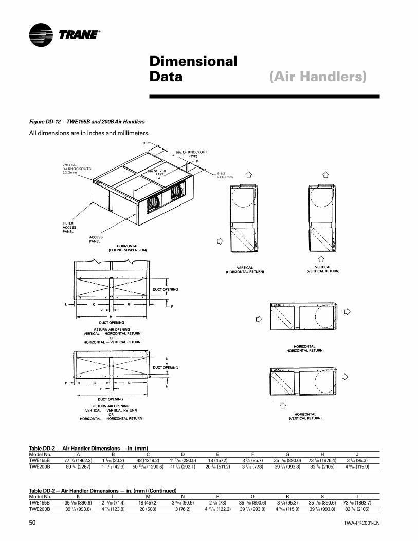
TWA-PRC001-EN50
Figure DD-12— TWE155B and 200B Air Handlers
All dimensions are in inches and millimeters.
Table DD-2 — Air Handler Dimensions — in. (mm)Model No. A B C D E F G H JTWE155B 77 1/4 (1962.2) 1 3/16 (30.2) 48 (1219.2) 11 7/16 (290.5) 18 (457.2) 3 3/8 (85.7) 35 1/16 (890.6) 73 7/8 (1876.4) 3 3/4 (95.3)TWE200B 89 1/4 (2267) 1 11/16 (42.9) 50 13/16 (1290.6) 11 1/2 (292.1) 20 1/8 (511.2) 3 1/16 (77.8) 39 1/8 (993.8) 82 7/8 (2105) 4 9/16 (115.9)
Table DD-2— Air Handler Dimensions — in. (mm) (Continued)Model No. K L M N P Q R S TTWE155B 35 1/16 (890.6) 2 13/16 (71.4) 18 (457.2) 3 9/16 (90.5) 2 7/8 (73) 35 1/16 (890.6) 3 3/4 (95.3) 35 1/16 (890.6) 73 3/8 (1863.7)TWE200B 39 1/8 (993.8) 4 7/8 (123.8) 20 (508) 3 (76.2) 4 13/16 (122.2) 39 1/8 (993.8) 4 9/16 (115.9) 39 1/8 (993.8) 82 7/8 (2105)
(Air Handlers)DimensionalData
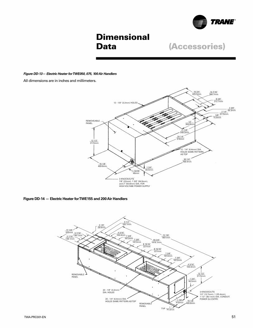
51TWA-PRC001-EN
DimensionalData (Accessories)
Figure DD-13— Electric Heater for TWE050, 075, 100 Air Handlers
All dimensions are in inches and millimeters.
Figure DD-14 — Electric Heater for TWE155 and 200 Air Handlers
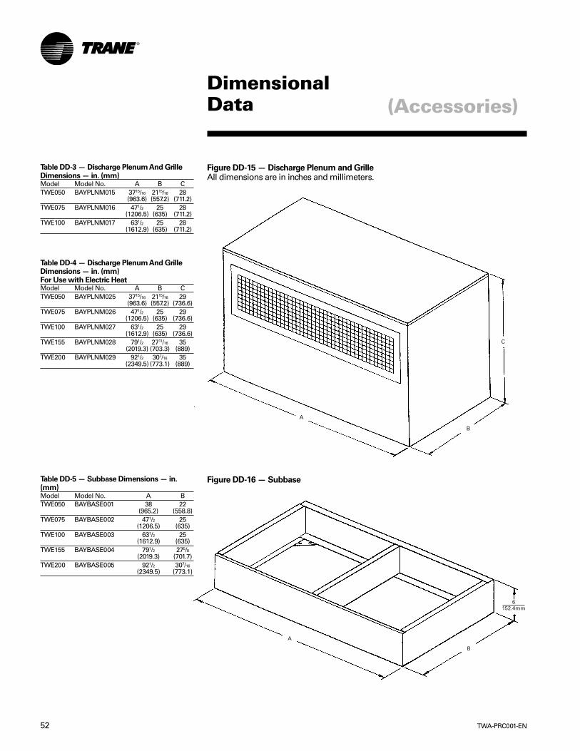
TWA-PRC001-EN52
DimensionalData (Accessories)
Figure DD-15 — Discharge Plenum and GrilleAll dimensions are in inches and millimeters.
Figure DD-16 — SubbaseTable DD-5 — Subbase Dimensions — in.(mm)Model Model No. A BTWE050 BAYBASE001 38 22
(965.2) (558.8)TWE075 BAYBASE002 471/2 25
(1206.5) (635)TWE100 BAYBASE003 631/2 25
(1612.9) (635)TWE155 BAYBASE004 791/2 275/8
(2019.3) (701.7)TWE200 BAYBASE005 921/2 307/16
(2349.5) (773.1)
Table DD-3 — Discharge Plenum And GrilleDimensions — in. (mm)Model Model No. A B CTWE050 BAYPLNM015 3715/16 2115/16 28
(963.6) (557.2) (711.2)TWE075 BAYPLNM016 471/2 25 28
(1206.5) (635) (711.2)TWE100 BAYPLNM017 631/2 25 28
(1612.9) (635) (711.2)
Table DD-4 — Discharge Plenum And GrilleDimensions — in. (mm)For Use with Electric HeatModel Model No. A B CTWE050 BAYPLNM025 3715/16 2115/16 29
(963.6) (557.2) (736.6)TWE075 BAYPLNM026 471/2 25 29
(1206.5) (635) (736.6)TWE100 BAYPLNM027 631/2 25 29
(1612.9) (635) (736.6)TWE155 BAYPLNM028 791/2 2711/16 35
(2019.3) (703.3) (889)TWE200 BAYPLNM029 921/2 307/16 35
(2349.5) (773.1) (889)

53TWA-PRC001-EN
Weights (Heat Pumps)
TWA075A, 100A
Table W-1 — Unit and Corner Weights — Lbs (Kg)Unit Shipping Net Corner WeightsModel No. Maximum — lbs (Kg) Maximum — lbs (Kg) 1 2 3 4TWA075A 390 343 112 89 63 79
(176.9) (155.6) (50.8) (40.4) (28.6) (35.8)TWA100A 468 414 146 106 68 94
(212.3) (187.8) (66.2) (48.1) (30.1) (42.6)TWA155B 816 740 195 186 175 184
(370.1) (335.7) (88.5) (84.4) (79.4) (83.5)TWA200B 970 885 253 250 190 192
(440.0) (401.4) (114.8) (113.4) (86.2) (87.1)
Table W-2 — Accessory Weights — Net Lbs (Kg)Unit RIS Steel Spring Anti Short Coil LowModel No. Isolators Isolators Cycle Timer Guard Thermostats AmbientTWA075A 2 12 1 8 1 23
(.9) (5.4) (.5) (3.6) (.5) (10.4)TWA100A 2 12 1 11 1 23
(.9) (5.4) (.5) (5) (.5) (10.4)TWA155B 2 12 1 22 1 23
(.9) (5.4) (.5) (10) (.5) (10.4)TWA200B 2 12 1 34 1 23
(.9) (5.4) (.5) (15.4) (.5) (10.4)
TWA155B, 200B

TWA-PRC001-EN54
Weights
Table W-3 — Air Handlers, Coils, And Corner Weights — Lbs (Kg)1
Unit Shipping Net Corner Weights — Vertical Corner Weights — HorizontalModel No. Maximum (lbs) Maximum (lbs) #1 #2 #3 #4 A B C DTWE050 298 262 59 59 59 59 54 64 64 54
(135) (118.9) (26.8) (26.8) (26.8) (26.8) (24.5) (29) (29.03) (24.5)TWE075 388 346 79 79 79 79 77 84 81 73
(176) (157) (35.9) (35.9) (35.9) (35.9) (35) (38.1) (36.7) (33.1)TWE100 473 419 107 107 107 107 102 113 113 102
(214.6) (190.1) (48.5) (48.5) (48.5) (48.5) (46.3) (51.3) (51.3) (46.3)TWE125 754 690 173 173 173 173 174 156 190 170
(342) (313) (78.5) (78.5) (78.5) (78.5) (79) (70.8) (86.2) (77.1)TWE200 886 820 204 204 204 204 185 228 221 179
(401.9) (372) (92.5) (92.5) (92.5) (92.5) (84) (103.4) (100.3) (81.2)Note:1. If application requires steam or hot water heating coils, field supplied isolators must be utilized.
Table W-4— Accessory Weights — Lbs (Kg)
RIS RIS Steel Spring Steel SpringDischarge Discharge Electric Isolator Isolator Isolator Isolator
Unit Plenum Plenum Return Heat Oversized Floor Suspended Floor SuspendedModel No. And Grille1 And Grill2 Air Grille Min. Max. Subbase Motor Mount Mount Mount MountTWE050 58 93 3 32/43 14 31 2 9 12 6
(26.3) (42.2) (1.4) (14.5/19.5) (6.4) (14.1) (.9) (4) (5.4) (2.7)TWE075 73 123 5 27/45 19 48 2 6 12 6
(33.1) (55.8) (2.3) (12.3/20.4) (8.6) (21.8) (.9) (2.7) (5.4) (2.7)TWE100 92 156 7 27/45 23 50 2 7 12 6
(41.7) (70.8) (3.2) (12.3/20.4) (10.4) (22.7) (.9) (3.2) (5.4) (2.7)TWE155 124 230 10 79/100 27 80 2 7 12 6
(56.3) (104.3) (4.5) (35.8/45.4) (12.3) (36.3) (.9) (3.2) (5.4) (2.7)TWE200 145 264 12 79/100 31 88 2 9 12 6
(65.8) (119.8) (5.4) (35.8/45.4) (14.06) (40) (.9) (4) (5.4) (2.7)Note:1. For use when no heat is supplied.2. For use with electric heat.
VerticalTWE050, 075, 100
VerticalTWE155, 200
HorizontalTWE155, 200
HorizontalTWE050, 075, 100
(Air Handlers)

55TWA-PRC001-EN
MechanicalSpecifications
Heat PumpsGeneralUnit shall be assembled on heavy gaugesteel mounting/lifting rails and shall beweather proofed. Unit shall include ahermetic scroll or reciprocatingcompressor(s), plate fin condenser coil,fans and motors, controls, and holdingcharge of nitrogen. Operating Rangeshall be between 115° F and 35° F incooling as standard from factory. Unitshall be UL 1995 listed and rated inaccordance with ARI Standard 210/240 or340/360.
CasingUnit casing shall be constructed of zinccoated, heavy gauge, galvanized steel.Exterior surfaces shall be cleaned,phosphatized, and finished with aweather-resistant baked enamel finish.Unit’s surface shall be tested 500 hoursin salt spray test. Unit shall haveremovable end panels which allowaccess to all major components andcontrols.
Refrigeration System — SingleCompressor
TWA075A, TWA100A units shall have asingle refrigeration circuit. Eachrefrigeration circuit has an integralsubcooling circuit. A refrigeration filterdrier, expansion valve, and check valvesshall be provided as standard. The unitshall have both a liquid line and suctiongas line service valve with gauge port.
Unit shall have one direct drive, Tranehermetic scroll compressor withcentrifugal oil pump providing positivelubrication to moving parts. Motor shallbe suction gas-cooled and shall have avoltage utilization range of plus or minus10 percent of nameplate voltage.Crankcase heater, discharge linethermostat, internal temperature, andcurrent-sensitive motor overloads shallbe included for maximum protection.Scroll type compressor shall provideinherently low vibration and noise byhaving no suction and discharge valves.External high and low pressure cutoutdevices shall be provided. Evaporatordefrost control provided in indoorblower coil unit shall preventcompressor slugging by temporarilyinterrupting compressor operation when
low evaporator coil temperatures areencountered.
Refrigeration System — DualCompressor
TWA155B, TWA200B units shall havetwo separate and independentrefrigeration circuits. Each refrigerationcircuit shall have an integral subcoolingcircuit. A refrigeration filter drier shall beprovided as standard. Unit shall haveboth a liquid line and suction gas lineservice valve with gauge ports.
Unit shall have two Trane direct drive,hermetic scroll compressors withcentrifugal oil pump and provide positivelubrication to all moving parts. Motorshall be suction gas-cooled and shallhave a voltage utilization range of plus orminus 10 percent of nameplate voltage.Crankcase heater, discharge linethermostat, internal temperature, andcurrent-sensitive motor overloads shallbe included for maximum protection.Scroll type compressor shall provideinherently low vibration and noise byhaving no suction and discharge valves.External high and low pressure cutoutdevices shall be provided. Evaporatordefrost control provided in indoorblower coil shall prevent compressorslugging by temporarily interruptingcompressor operation when lowevaporator coil temperatures areencountered.
Condenser CoilCoils shall be internally finned or smoothbore, 3/8" (10mm) copper tubesmechanically bonded to a configuredaluminum plate fin as standard. Coilshall be factory pressure and leak testedto 420 psig (2,930 kPa) air pressure.Metal grilles with PVC coating for coilprotection is optional.
Condenser Fan And Motor(s)Direct-drive, statically and dynamicallybalanced, 26 or 28 inch (660 or 711 mm)propeller fan(s) with aluminum bladesand electro-coated steel hubs shall beused in draw-through vertical dischargeposition. Either permanently lubricatedtotally enclosed or open constructiontype motors shall be provided and shallhave built-in current and thermaloverload protection. Motor(s) shall haveeither ball or sleeve bearing type.
ControlsHeat pump units shall be completelyfactory wired with necessary controlsand contactor pressure lugs or terminalblock for power wiring. Control wiringshall be 24-volt control circuit whichincludes fusing and control transformer.Units shall provide external location formounting a fused disconnect device.Time delay timers to preventcompressors in dual compressor unitsfrom simultaneous start-up and anti-recycle timers are available as optionalaccessories.
Defrost ControlsElectronic timed initiated, temperatureterminated defrost system with choiceof 50, 70, or 90 minute cycle shall beincluded. Timed override limits defrostcycle to 10 minutes.
Low Ambient OperationStandard units shall start and operate toapproximately 35° F (1.7° C) whenmatched with Trane air handlers andcoils. Optional head pressure controlaccessory permits operation to 0° F(-17.8° C).
ACCESSORIESLow Ambient Head Pressure Control —This accessory shall modulate the RPMof unit outdoor fan motor in responseto outdoor ambient temperatures andliquid line temperature. Accessoryprovides unit cooling operation tooutdoor temperatures of 0° F (-17.8° C).
Vibration Isolation Packages — Thisaccessory shall reduce transmission ofnoise and vibration to buildingstructures, equipment, and adjacentspaces. Packages shall be available ineither neoprene-in-shear or spring-flextypes.
Time Delay Relay — This accessoryshall prevent compressors in dualcompressor unit from coming on linesimultaneously. Timer shall be 24-volt,60 cycle, with four minute timingperiod.
Anti-Short-Cycle Timer — Thisaccessory shall prevent rapid on-offcompressor cycling in light loadconditions by not allowing compressorto operate for 5-7 minutes uponshutdown. This accessory shall consistof a 24-volt, 60 cycle, solid state timingdevice with either 5 or 7 minute fixed-off timing period.

TWA-PRC001-EN56
Air HandlersGeneralAir handler units shall be completelyfactory assembled including coil,condensate drain pan, fan motor(s),filters, and controls in an insulatedcasing that can be applied in eithervertical or horizontal configuration. Unitshall be rated and tested in accordancewith ARI standard 210/240 or 340/360.Unit shall be UL listed and labeled inaccordance with UL 1995 for indoorblower coil units.
CasingUnit casing shall be constructed of zinccoated, heavy gauge, galvanized steel.Exterior surfaces shall be cleaned,phosphatized, and finished with aweather-resistant baked enamel finish.Casing shall be completely insulatedwith cleanable, foil faced, fire-retardant,permanent, odorless, glass fibermaterial. All insulation edges shall beeither captured or sealed. Knockoutsshall be provided for unit electricalpower and refrigerant pipingconnections. Captive screws shall bestandard on all access panels.
Refrigeration SystemThe TWE050A, TWE075A, TWE100A unitsshall have a single refrigeration circuitand the TWE100B, TWE155B, TWE200Bunits shall have dual refrigerationcircuits. Each refrigeration circuit iscontrolled by a factory installed thermalexpansion valve.
Evaporator CoilConfigured aluminum fin surface shallbe mechanically bonded to 3/8" (10 mm)
Condenser Coil Guard — Metal grillewith PVC coating shall be provided toalleviate coil damage.
Black Epoxy Coated Condenser Coil —This factory installed option is designedto provide corrosion protection of aircooled condenser coils for seacoastapplication. The black epoxy coilprotection is a factory applied thermosetvinyl coating, bonded to normalaluminum fin stock. The uniformthickness of the bonded vinyl layerexhibits excellent corrosion protection insalt spray tests performed in accordancewith ASTM B177.
internally enhanced copper tubing andshall be factory pressure and leak testedat 375 psig (2586 kPa). Coil is arrangedfor draw-through airflow and shallprovide a double sloped condensatedrain pan constructed of PVC plastic. Thedrain pan shall be removable forcleaning. The condensate drain pan canbe installed in any of four positionsallowing for vertical or horizontalapplication and providing externalconnections on either side of the unit.
Evaporator FanDouble inlet, double width, forwardcurved, centrifugal-type fan(s) withadjustable belt drive shall be standard.Thermal overload protection shall bestandard on motor. Fan and motorbearings shall be permanentlylubricated. Oversized motors shall beavailable as an option for high staticapplication. All indoor fan motors meetthe U.S. Energy Policy Act of 1992(EPACT)
ControlsMagnetic evaporator fan contactor, lowvoltage terminal strip, check valve(s), andsingle point power entry shall beincluded. All necessary controls shall befactory-installed and wired. Evaporatordefrost control shall be included toprevent compressor slugging bytemporarily interrupting compressoroperation when low evaporator coiltemperatures are encountered.
FiltersOne inch, throw-away filters shall bestandard on TWE050A, TWE075A,TWE100A and TWE120B model airhandlers. Filters shall be accessible fromthe side coil access panel. Filter rack canbe field converted to two inch capability.Two inch, throw-away filters shall bestandard on TWE155B and TWE200Bmodels.
ACCESSORIES
Electric Heaters — UL and CSAapproved electric heat modules shall beavailable for installation directly on fandischarge. Electric heaters shall beavailable in a wide range of capacitieswith one or two stage control, single-point electric power connection, andterminal strip connections. Electricheater elements shall be constructed ofheavy-duty nickel chromium elements
internally wye connected on 400 volt,three phase. Each 400 volt heater shallhave automatic line break high limitcontrols.
Discharge Plenums and Grilles —Accessory discharge plenums shall beavailable for vertical, free dischargeapplications. Plenums shall beconstructed of heavy-gauge, zinc coated,galvanized steel finished with bakedenamel to match the air handler unit.Grilles shall be satin finished aluminumand have four-way adjustable louvers.
Return Air Grilles — Accessory return airgrille shall be provided for vertical front,free return applications. Grilles shall beinstalled in place of the front lower sidepanel. Grille shall be satin finishedaluminum with non-adjustable louvers.
Mounting Subbase — The accessoryshall be available for vertical floor mountconfigurations. Subbase shall beconstructed of heavy gauge, zinc coated,galvanized steel with baked enamelfinish to match air handler unit. Subbaseis required in the vertical air flowapplication for condensate draintrapping and when isolators arerequired.
Vibration Isolators — This accessoryshall reduce transmission of noise andvibration to building structures,equipment, and adjacent spaces.Packages shall be available in eitherneoprene-in shear or spring-flex types infloor or suspended mountings.
Oversized Motors — Field installedoversized motors shall be available forhigh static pressure applications.
CONTROL OPTIONS
Standard Indoor Thermostats — Twostage heating and cooling operation orone stage heating and coolingthermostats shall be available in eithermanual or automatic changeover.
Programmable Electronic Night SetbackThermostat — The option shall provideheating setback and cooling setup with 7-day programming capability.
Outdoor Thermostat — This option shallprovide staging control of electricheaters based on a set outdoortemperature.
MechanicalSpecifications

57TWA-PRC001-EN

TWA-PRC001-EN58

59TWA-PRC001-EN

The Trane Company
An American Standard Companywww.trane.com
For more information contact yourlocal distributor (dealer), local districtoffice, or e-mail us [email protected]
Since The Trane Company has a policy of continuous product and product data improvement, it reserves theright to change design and specifications without notice.
Literature Order Number
File Number
Supersedes
Stocking Location
TWA-PRC001-EN
PL-UN-TWA-PRC001-EN-07-00
TWA-PRC001-EN-05/98
Inland - LaCrosse


