PARTS BREAKDOWN ..................................................................40
1
2
3
4
5
6
7
8
9
10
11
12
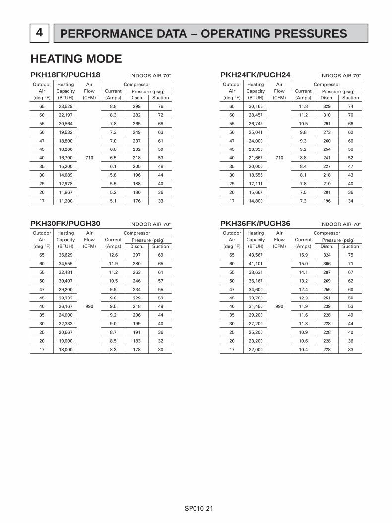
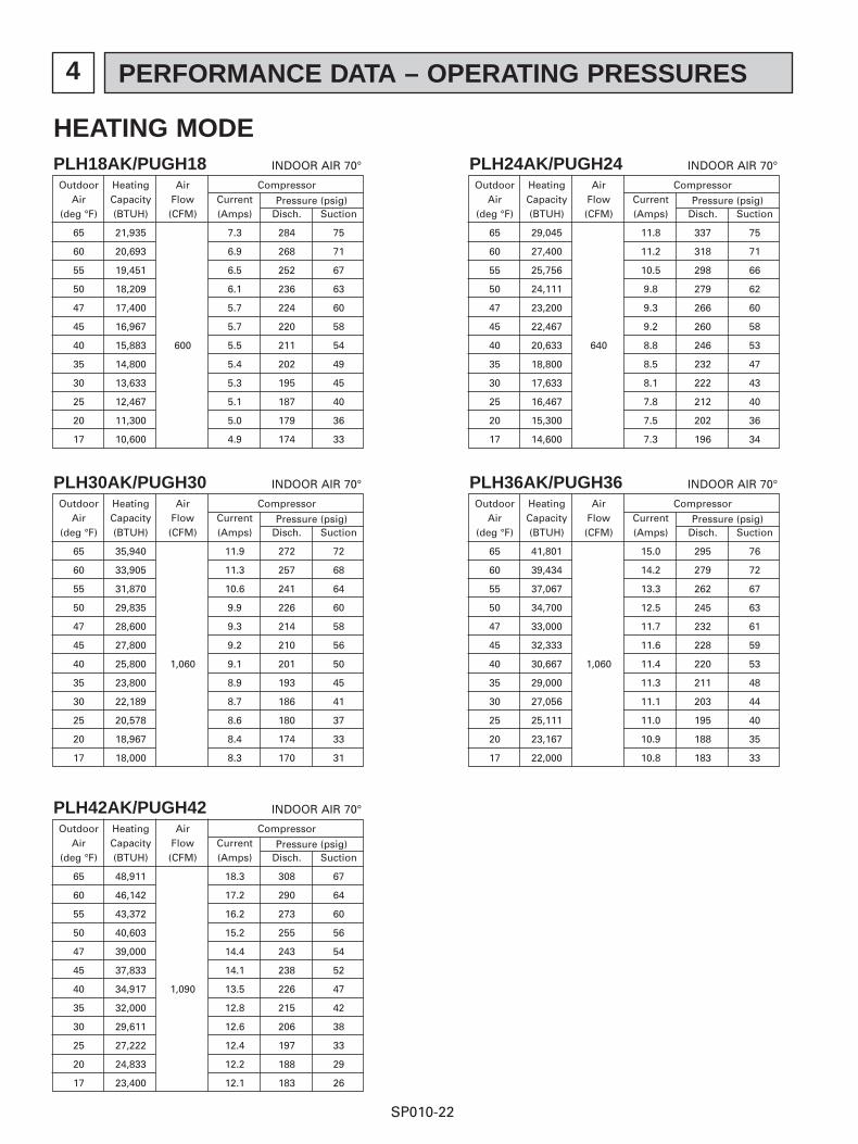
1 FEATURES
SP010-2
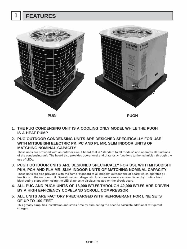
1. THE PUG CONDENSING UNIT IS A COOLING ONLY MODEL WHILE THE PUGH IS A HEAT PUMP
2. PUG OUTDOOR CONDENSING UNITS ARE DESIGNED SPECIFICALLY FOR USE WITH MITSUBISHI ELECTRIC PK, PC AND PL MR. SLIM INDOOR UNITS OF MATCHING NOMINAL CAPACITY These units are provided with an outdoor circuit board that is “standard to all models” and operates all functionsof the condensing unit. The board also provides operational and diagnostic functions to the technician through theuse of LEDs.
3. PUGH OUTDOOR UNITS ARE DESIGNED SPECIFICALLY FOR USE WITH MITSUBISHI PKH, PCH AND PLH MR. SLIM INDOOR UNITS OF MATCHING NOMINAL CAPACITY These units are also provided with the same "standard to all models" outdoor circuit board which operates allfunctions of the outdoor unit. Operational and diagnostic functions are easily accomplished by routine trou-bleshooting steps when using the LED diagnostic displays located on the circuit board.
4. ALL PUG AND PUGH UNITS OF 18,000 BTU’S THROUGH 42,000 BTU’S ARE DRIVEN BY A HIGH EFFICIENCY COPELAND SCROLL COMPRESSOR
5. ALL UNITS ARE FACTORY PRECHARGED WITH REFRIGERANT FOR LINE SETS OF UP TO 100 FEET This greatly simplifies installation and saves time by eliminating the need to calculate additional refrigerantcharges.
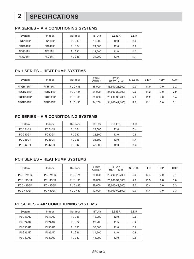
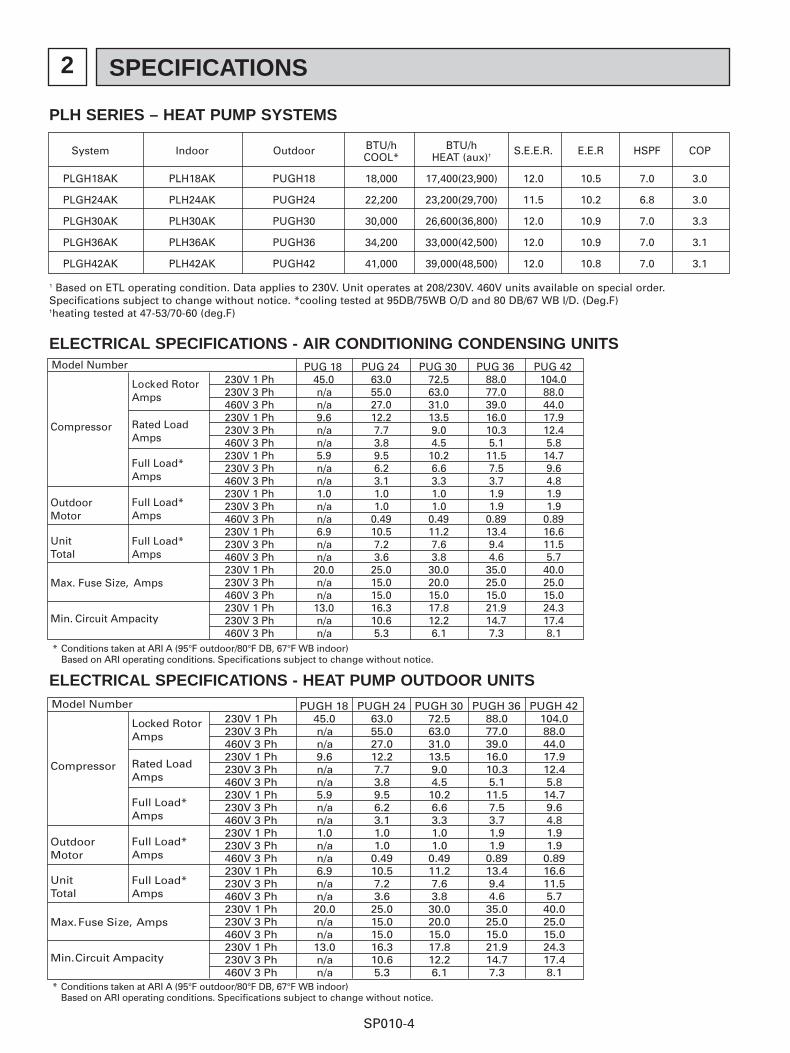
ELECTRICAL SPECIFICATIONS - AIR CONDITIONING CONDENSING UNITS
1 Based on ETL operating condition. Data applies to 230V. Unit operates at 208/230V. 460V units available on special order.Specifications subject to change without notice. *cooling tested at 95DB/75WB O/D and 80 DB/67 WB I/D. (Deg.F)†heating tested at 47-53/70-60 (deg.F)
ELECTRICAL SPECIFICATIONS - HEAT PUMP OUTDOOR UNITS
Compressor
Locked RotorAmps
Rated LoadAmps
OutdoorMotor
UnitTotal
Full Load*Amps
Full Load*Amps
Full Load*Amps
Max. Fuse Size, Amps
Min. Circuit Ampacity
Model Number
* Conditions taken at ARI A (95°F outdoor/80°F DB, 67°F WB indoor)Based on ARI operating conditions. Specifications subject to change without notice.
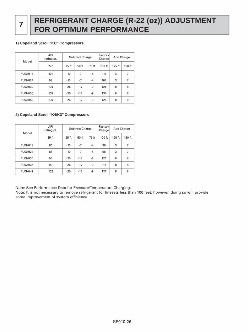
Note: See Performance Data for Pressure/Temperature Charging.Note: It is not necessary to remove refrigerant for linesets less than 100 feet; however, doing so will providesome improvement of system efficiency.
Model
ARIrating pt.
25 ft25 ft
-10
-10
-25
-25
-25
50 ft
-7
-7
-17
-17
-17
75 ft
-4
-4
-9
-9
-9
100 ft
111
108
125
130
125
125 ft
3
3
8
8
8
150 ft
7
7
8
8
8
Subtract Charge Add ChargeFactoryCharge
PUG/H18
PUG/H24
PUG/H30
PUG/H36
PUG/H42
101
98
100
105
100
1) Copeland Scroll “KC” Compressors
Model
ARIrating pt.
25 ft25 ft
-10
-10
-25
-25
-25
50 ft
-7
-7
-17
-17
-17
75 ft
-4
-4
-9
-9
-9
100 ft
90
98
121
115
127
125 ft
3
3
8
8
8
150 ft
7
7
8
8
8
Subtract Charge Add ChargeFactoryCharge
PUG/H18
PUG/H24
PUG/H30
PUG/H36
PUG/H42
80
88
96
90
102
2) Copeland Scroll “K4/K3” Compressors
SP010-27
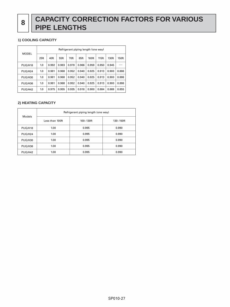
8 CAPACITY CORRECTION FACTORS FOR VARIOUSPIPE LENGTHS
MODEL
Refrigerant piping length (one way)
PUG/H18
PUG/H24
PUG/H30
PUG/H36
PUG/H42
1.0
1.0
1.0
1.0
1.0
25ft
0.992
0.981
0.981
0.981
0.975
40ft
0.983
0.968
0.968
0.968
0.955
55ft
0.978
0.952
0.952
0.952
0.935
70ft
0.966
0.940
0.940
0.940
0.918
85ft
0.959
0.925
0.925
0.925
0.900
100ft
0.950
0.913
0.913
0.913
0.884
115ft
0.945
0.900
0.900
0.900
0.869
130ft
0.886
0.886
0.886
0.855
150ft
1) COOLING CAPACITY
Models
Refrigerant piping length (one way)
PUG/H18
PUG/H24
PUG/H30
PUG/H36
PUG/H42
1.00
1.00
1.00
1.00
1.00
Less than 100ft
0.995
0.995
0.995
0.995
0.995
100~130ft
0.990
0.990
0.990
0.990
0.990
130~150ft
2) HEATING CAPACITY
9 MICROPROCESSOR CONTROL
SP010-28
1. COOLING/HEATING OPERATIONOutdoor unit operation is activated by delivery of a 12VDC signal from the indoor unit. Cooling only units have 2 lowvoltage control wires from the indoor unit to the outdoor unit. Heat pump units have 3 low voltage control wires fromthe indoor to the outdoor unit. The function of these wires are:
● Wire #1: Common
● Wire #2: Initiates operation of the compressor and outdoor fan when 12VDC is supplied from the indoor unit.
● Wire #3: Initiates operation of the reversing valve for heating operation. 12VDC is present constantly when the indoor unit mode is set to heat.
2. OUTDOOR ABNORMALITY DETECTION BY INDOOR UNIT (P8 FAULT CODE)
A. The indoor unit constantly monitors the difference between return air temperature and indoor coil temperature.During a call for cooling, if after several minutes of operation (approx 10 minutes) the indoor coil does notbecome at least 9 degrees colder than the return air temperature, the indoor circuit board will cause the systemto shut down. At this point the problem code “P8” will be displayed at the indoor unit remote controller and the12VDC signal to the outdoor unit will be stopped.
B. The “P8” code does not necessarily mean that the failure is caused by the outdoor unit. It simply means that theindoor coil did not become colder than the return air during a call for cooling.
C. During the heat mode the indoor coil temperature must get at least 9 degrees warmer than the return air tem-perature. If this temperature difference is not achieved the unit will shut down as indicated above.
D. If a “P8” code is displayed:
i. Turn the indoor remote controller off and back on to reset it.
ii. Set the remote controller to a “call” for cooling.
iii. At the indoor unit 12VDC control terminals check to see if 12VDC is present on the #1 and #2 wires.
1. You may encounter a 3 minute delay in cooling or a 6 minute delay in heating before the 12VDC signalis generated.
iv. If 12VDC is present and the outdoor unit is not running the problem is not caused by the indoor unit and thefollowing should be checked:
1. Check the 12VDC terminals at the outdoor unit for 12VDC. The polarity must be the same as that of theindoor meaning wire one at the indoor must be on the same terminal at the outdoor. If they arereversed no harm will be done but the unit will not operate.
a. If no 12VDC signal is present when 12VDC is available at the indoor unit check for a break/open in thecontrol wire.
b. If 12VDC is present insure polarity is correct. If polarity is correct and a 12VDC signal is present checkthe LED indicators on the outdoor board.
i. Is the “Status” LED lit constantly? If so the outdoor board is in time delay, wait for it to expire(make sure the 12VDC signal is still available from the indoor unit).
ii. Is the “#2” LED lit? This indicates that the board is receiving 12VDC from the indoor unit.
NO LED: Recheck for 12VDC on the control wires, check for correct polarity and check the wiresfrom the terminal block to the board.
LIT: The board should be outputting 24 VAC to the compressor contactor and line voltage to thefan (unless in low ambient control). Is the compressor/fan operating?
YES: System is OK
NO: Is the “Status LED” flashing?
NO: Bad outdoor board
YES: 2 Flash sequence indicates that the High Pressure Switch is open. 4 Flash sequence indicatesthat the Low Pressure Safety Switch is open
9 MICROPROCESSOR CONTROL
SP010-29
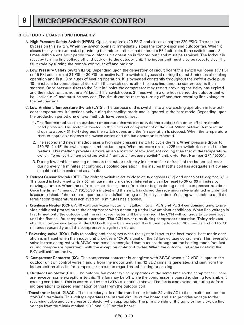
3. OUTDOOR BOARD FUNCTIONALITY
A. High Pressure Safety Switch (HPSS). Opens at approx 420 PSIG and closes at approx 320 PSIG. There is nobypass on this switch. When the switch opens it immediately stops the compressor and outdoor fan. When itcloses the system can restart providing the indoor unit has not entered a P8 fault code. If the switch opens 3times within a one hour period the outdoor unit operation is “locked out” and must be serviced. The lockout isreset by turning line voltage off and back on to the outdoor unit. The indoor unit must also be reset to clear thefault code by turning the remote controller off and back on.
B. Low Pressure Safety Switch (LPS). Depending upon the generation of circuit board this switch will open at 7 PSIor 15 PSI and close at 21 PSI or 30 PSI respectively. The switch is bypassed during the first 3 minutes of coolingoperation and first 10 minutes of heating operation. It is bypassed constantly throughout the defrost cycle plus10 minutes after completion of defrost. If the switch opens after the specified time the compressor is thenstopped. Once pressure rises to the “cut in” point the compressor may restart providing the delay has expiredand the indoor unit is not in a P8 fault. If the switch opens 3 times within a one hour period the outdoor unit willbe “locked out” and must be serviced. The circuit can be reset by turning off and then resetting line voltage tothe outdoor unit.
C. Low Ambient Temperature Switch (LATS). The purpose of this switch is to allow cooling operation in low out-door temperatures. It functions only during the cooling mode and is ignored in the heat mode. Depending uponthe production period one of two methods have been utilized.
1. The first method uses an outdoor temperature thermostat to cycle the outdoor fan on or off to maintainhead pressure. The switch is located in the electrical compartment of the unit. When outdoor temperaturedrops to approx 31 (+/-2) degrees the switch opens and the fan operation is stopped. When the temperaturerises to approx 37 degrees the switch closes and the fan operation is restored.
2. The second and newer method uses a high side pressure switch to cycle the fan. When pressure drops to150 PSI (+/-15) the switch opens and the fan stops. When pressure rises to 225 the switch closes and the fanrestarts. This method provides a more reliable method of low ambient cooling than that of the temperatureswitch. To convert a “temperature switch” unit to a “pressure switch” unit, order Part Number GPN490001.
3. During low ambient cooling operation the indoor unit may initiate an “air defrost” of the indoor coil onceduring every 16 minutes of continuous cooling operation. This insures that the coil has adequate airflow andshould not be considered as a fault.
D. Defrost Sensor Switch (DFT). The defrost switch is set to close at 35 degrees (+/-7) and opens at 65 degrees (+/-5).The board is factory set with a 60 minute minimum defrost interval and can be reset to 30 or 90 minutes bymoving a jumper. When the defrost sensor closes, the defrost timer begins timing out the compressor run time.Once the timer “times out” (30/60/90 minutes) and the switch is closed the reversing valve is shifted and defrostis accomplished. If the room temperature is satisfied during a defrost cycle, the defrosting will continue until thetermination temperature is achieved or 10 minutes has elapsed.
E. Crankcase Heater (CCH). A 40 watt crankcase heater is installed into all PUG and PUGH condensing units to pro-vide additional protection to the compressor when operating under low ambient conditions. When line voltage isfirst turned onto the outdoor unit the crankcase heater will be energized. The CCH will continue to be energizeduntil the first call for compressor operation. The CCH never runs during compressor operation. Thirty minutesafter the compressor turns off the CCH will again be energized. It will then cycle on for 30 minutes and off for 30minutes repeatedly until the compressor is again turned on.
F. Reversing Valve (RXV). Fails to cooling and energizes when the system is set to the heat mode. Heat mode oper-ation is initiated when the indoor unit provides a 12VDC signal on the #3 low voltage control wire. The reversingvalve is then energized with 24VAC and remains energized continuously throughout the heating mode (not justduring compressor operation), with the exception of defrost cycles. When the outdoor unit enters defrost theRXV will shift on the fly.
G. Compressor Contactor (CC). The compressor contactor is energized with 24VAC when a 12 VDC is input to theoutdoor unit on control wires 1 and 2 from the indoor unit. This 12 VDC signal is generated and sent from theindoor unit on all calls for compressor operation regardless of heating or cooling.
H. Outdoor Fan Motor (ODF). The outdoor fan motor typically operates at the same time as the compressor. Thereare however some exceptions to this. The fan may be off while the compressor is operating during low ambientcooling conditions. This is controlled by the LATS as identified above. The fan is also cycled off during defrost-ing operations to speed elimination of frost from the outdoor coil.
I. Transformer Input (24VAC). The secondary side of the transformer inputs 24 volts AC to the circuit board on the“24VAC” terminals. This voltage operates the internal circuits of the board and also provides voltage to thereversing valve and compressor contactor when appropriate. The primary side of the transformer picks up linevoltage from terminals marked “L1” and “L2” on the board.
9 MICROPROCESSOR CONTROL
SP010-30
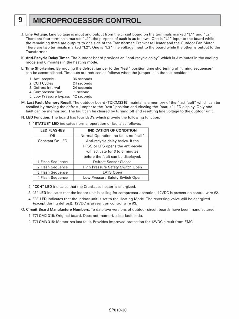
J. Line Voltage. Line voltage is input and output from the circuit board on the terminals marked “L1” and “L2”.There are four terminals marked “L1”, the purpose of each is as follows. One is “L1” input to the board whilethe remaining three are outputs to one side of the Transformer, Crankcase Heater and the Outdoor Fan Motor.There are two terminals marked “L2”. One is “L2” line voltage input to the board while the other is output to theTransformer.
K. Anti-Recycle Delay Timer. The outdoor board provides an “anti-recycle delay” which is 3 minutes in the coolingmode and 6 minutes in the heating mode.
L. Time Shortening. By moving the defrost jumper to the “test” position time shortening of “timing sequences”can be accomplished. Timeouts are reduced as follows when the jumper is in the test position:
M. Last Fault Memory Recall. The outdoor board (TDICM3315) maintains a memory of the “last fault” which can berecalled by moving the defrost jumper to the “test” position and viewing the “status” LED display. Only onefault can be memorized. The fault can be cleared by turning off and resetting line voltage to the outdoor unit.
N. LED Function. The board has four LED’s which provide the following function:
1. “STATUS” LED indicates normal operation or faults as follows:
2. “CCH” LED indicates that the Crankcase heater is energized.
3. “2” LED indicates that the indoor unit is calling for compressor operation, 12VDC is present on control wire #2.
4. “3” LED indicates that the indoor unit is set to the Heating Mode. The reversing valve will be energized(except during defrost). 12VDC is present on control wire #3.
O. Circuit Board Manufacture Numbers. To date two versions of outdoor circuit boards have been manufactured.
1. T7I CM2 315: Original board. Does not memorize last fault code.
2. T7I CM3 315: Memorizes last fault. Provides improved protection for 12VDC circuit from EMC.
LED FLASHES INDICATION OF CONDITION
Off Normal Operation, no fault, no “call”Constant On LED Anti-recycle delay active. If the
HPSS or LPS opens the anti-recylewill activate for 3 to 6 minutes
before the fault can be displayed.1 Flash Sequence Defrost Sensor Closed2 Flash Sequence High Pressure Safety Switch Open3 Flash Sequence LATS Open4 Flash Sequence Low Pressure Safety Switch Open
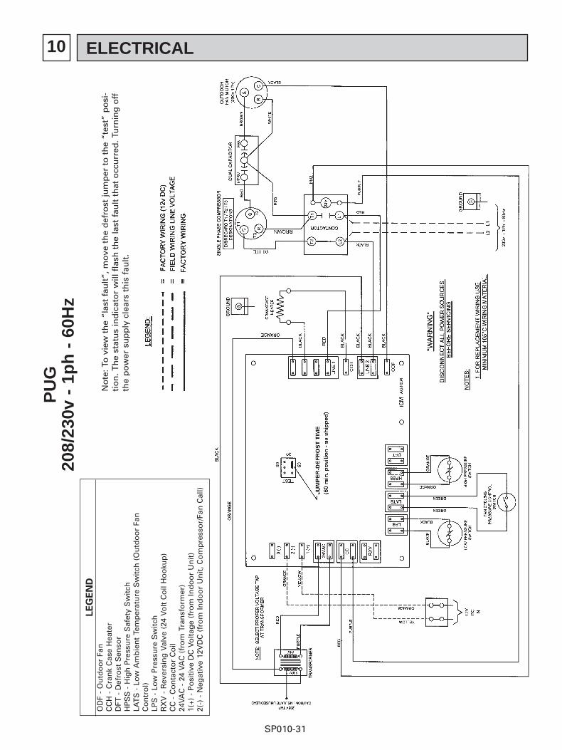
10 ELECTRICAL
SP010-31
PU
G20
8/23
0v -
1p
h -
60H
z
No
te: T
o v
iew
th
e “l
ast
fau
lt”,
mo
ve t
he
def
rost
jum
per
to
th
e “t
est”
po
si-
tio
n. T
he
stat
us
ind
icat
or
will
fla
sh t
he
last
fau
lt t
hat
occ
urr
ed. T
urn
ing
off
the
po
wer
su
pp
ly c
lear
s th
is f
ault
.
LE
GE
ND
OD
F -
Ou
tdo
or
Fan
CC
H -
Cra
nk
Cas
e H
eate
rD
FT -
Def
rost
Sen
sor
HP
SS
- H
igh
Pre
ssu
re S
afet
y S
wit
chLA
TS
- L
ow
Am
bie
nt
Tem
per
atu
re S
wit
ch (
Ou
tdo
or
Fan
Co
ntr
ol)
LPS
- L
ow
Pre
ssu
re S
wit
chR
XV
- R
ever
sin
g V
alve
(24
Vo
lt C
oil
Ho
oku
p)
CC
- C
on
tact
or
Co
il24
VAC
- 2
4 VA
C (
fro
m T
ran
sfo
rmer
)1(
+) -
Po
siti
ve D
C V
olt
age
(fro
m In
do
or
Un
it)
2(-)
- N
egat
ive
12V
DC
(fr
om
Ind
oo
r U
nit
, Co
mp
ress
or/
Fan
Cal
l)
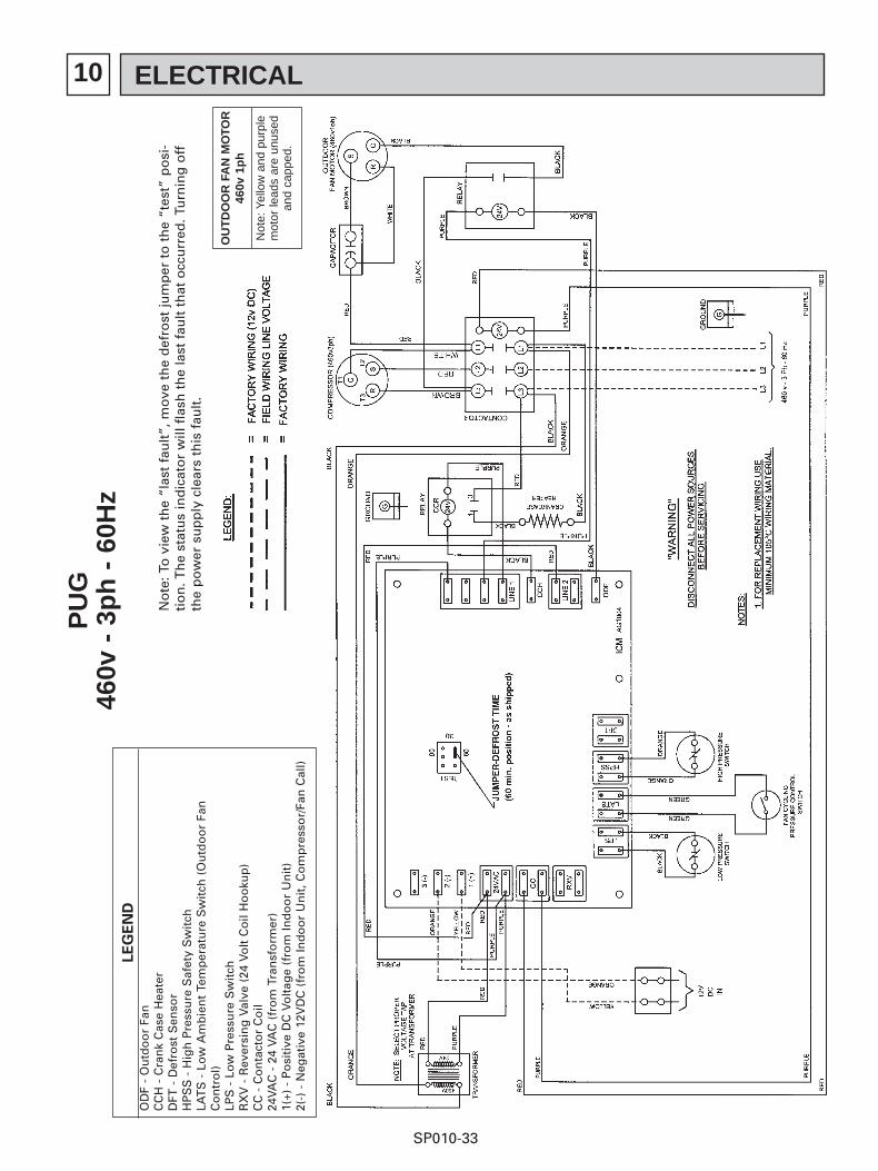
10 ELECTRICAL
SP010-32
PU
G20
8/23
0v -
3p
h -
60H
z
No
te: T
o v
iew
th
e “l
ast
fau
lt”,
mo
ve t
he
def
rost
jum
per
to
th
e “t
est”
po
si-
tio
n. T
he
stat
us
ind
icat
or
will
fla
sh t
he
last
fau
lt t
hat
occ
urr
ed. T
urn
ing
off
the
po
wer
su
pp
ly c
lear
s th
is f
ault
.
LE
GE
ND
OD
F -
Ou
tdo
or
Fan
CC
H -
Cra
nk
Cas
e H
eate
rD
FT -
Def
rost
Sen
sor
HP
SS
- H
igh
Pre
ssu
re S
afet
y S
wit
chLA
TS
- L
ow
Am
bie
nt
Tem
per
atu
re S
wit
ch (
Ou
tdo
or
Fan
Co
ntr
ol)
LPS
- L
ow
Pre
ssu
re S
wit
chR
XV
- R
ever
sin
g V
alve
(24
Vo
lt C
oil
Ho
oku
p)
CC
- C
on
tact
or
Co
il24
VAC
- 2
4 VA
C (
fro
m T
ran
sfo
rmer
)1(
+) -
Po
siti
ve D
C V
olt
age
(fro
m In
do
or
Un
it)
2(-)
- N
egat
ive
12V
DC
(fr
om
Ind
oo
r U
nit
, Co
mp
ress
or/
Fan
Cal
l)
10 ELECTRICAL
SP010-33
PU
G46
0v -
3p
h -
60H
z
No
te: T
o v
iew
th
e “l
ast
fau
lt”,
mo
ve t
he
def
rost
jum
per
to
th
e “t
est”
po
si-
tio
n. T
he
stat
us
ind
icat
or
will
fla
sh t
he
last
fau
lt t
hat
occ
urr
ed. T
urn
ing
off
the
po
wer
su
pp
ly c
lear
s th
is f
ault
.
LE
GE
ND
OD
F -
Ou
tdo
or
Fan
CC
H -
Cra
nk
Cas
e H
eate
rD
FT -
Def
rost
Sen
sor
HP
SS
- H
igh
Pre
ssu
re S
afet
y S
wit
chLA
TS
- L
ow
Am
bie
nt
Tem
per
atu
re S
wit
ch (
Ou
tdo
or
Fan
Co
ntr
ol)
LPS
- L
ow
Pre
ssu
re S
wit
chR
XV
- R
ever
sin
g V
alve
(24
Vo
lt C
oil
Ho
oku
p)
CC
- C
on
tact
or
Co
il24
VAC
- 2
4 VA
C (
fro
m T
ran
sfo
rmer
)1(
+) -
Po
siti
ve D
C V
olt
age
(fro
m In
do
or
Un
it)
2(-)
- N
egat
ive
12V
DC
(fr
om
Ind
oo
r U
nit
, Co
mp
ress
or/
Fan
Cal
l)
OU
TD
OO
R F
AN
MO
TOR
460v
1p
h
Not
e: Y
ello
w a
nd p
urpl
e m
otor
lead
s ar
e un
used
an
d ca
pped
.
10 ELECTRICAL
SP010-34
PU
GH
208/
230v
- 1
ph
- 6
0Hz
No
te: T
o v
iew
th
e “l
ast
fau
lt”,
mo
ve t
he
def
rost
jum
per
to
th
e “t
est”
po
si-
tio
n. T
he
stat
us
ind
icat
or
will
fla
sh t
he
last
fau
lt t
hat
occ
urr
ed. T
urn
ing
off
the
po
wer
su
pp
ly c
lear
s th
is f
ault
.
LE
GE
ND
OD
F -
Ou
tdo
or
Fan
CC
H -
Cra
nk
Cas
e H
eate
rD
FT -
Def
rost
Sen
sor
HP
SS
- H
igh
Pre
ssu
re S
afet
y S
wit
chLA
TS
- L
ow
Am
bie
nt
Tem
per
atu
re S
wit
ch (
Ou
tdo
or
Fan
Co
ntr
ol)
LPS
- L
ow
Pre
ssu
re S
wit
chR
XV
- R
ever
sin
g V
alve
(24
Vo
lt C
oil
Ho
oku
p)
CC
- C
on
tact
or
Co
il24
VAC
- 2
4 VA
C (
fro
m T
ran
sfo
rmer
)1(
+) -
Po
siti
ve D
C V
olt
age
(fro
m In
do
or
Un
it)
2(-)
- N
egat
ive
12V
DC
(fr
om
Ind
oo
r U
nit
, Co
mp
ress
or/
Fan
Cal
l)3(
-) -
Neg
ativ
e 12
VD
C (
fro
m In
do
or
Un
it, H
eat
Mo
de)
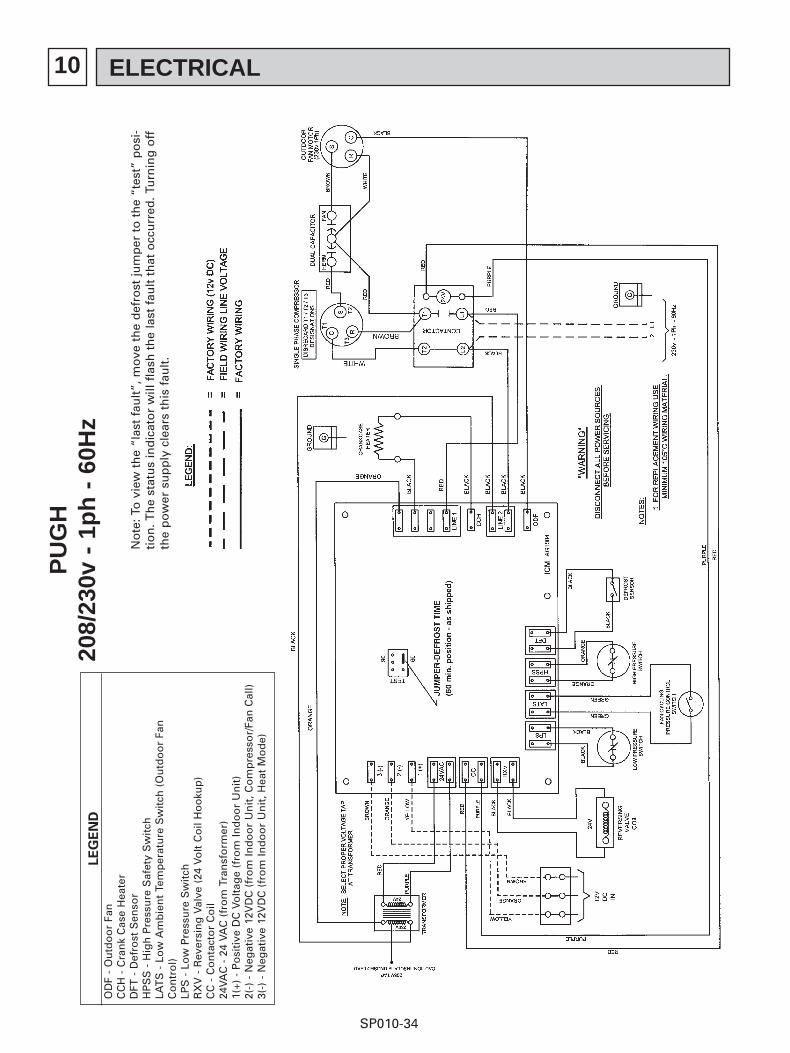
10 ELECTRICAL
SP010-35
PU
GH
208/
230v
- 3
ph
- 6
0Hz
No
te: T
o v
iew
th
e “l
ast
fau
lt”,
mo
ve t
he
def
rost
jum
per
to
th
e “t
est”
po
si-
tio
n. T
he
stat
us
ind
icat
or
will
fla
sh t
he
last
fau
lt t
hat
occ
urr
ed. T
urn
ing
off
the
po
wer
su
pp
ly c
lear
s th
is f
ault
.
LE
GE
ND
OD
F -
Ou
tdo
or
Fan
CC
H -
Cra
nk
Cas
e H
eate
rD
FT -
Def
rost
Sen
sor
HP
SS
- H
igh
Pre
ssu
re S
afet
y S
wit
chLA
TS
- L
ow
Am
bie
nt
Tem
per
atu
re S
wit
ch (
Ou
tdo
or
Fan
Co
ntr
ol)
LPS
- L
ow
Pre
ssu
re S
wit
chR
XV
- R
ever
sin
g V
alve
(24
Vo
lt C
oil
Ho
oku
p)
CC
- C
on
tact
or
Co
il24
VAC
- 2
4 VA
C (
fro
m T
ran
sfo
rmer
)1(
+) -
Po
siti
ve D
C V
olt
age
(fro
m In
do
or
Un
it)
2(-)
- N
egat
ive
12V
DC
(fr
om
Ind
oo
r U
nit
, Co
mp
ress
or/
Fan
Cal
l)3(
-) -
Neg
ativ
e 12
VD
C (
fro
m In
do
or
Un
it, H
eat
Mo
de)
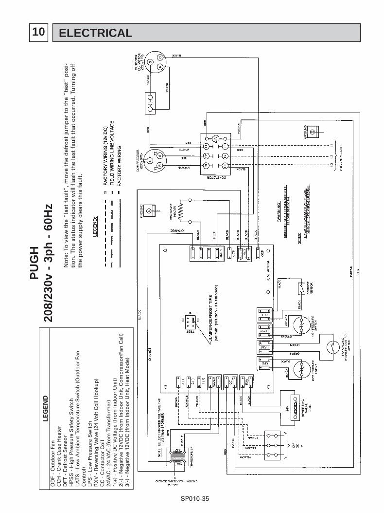
10 ELECTRICAL
SP010-36
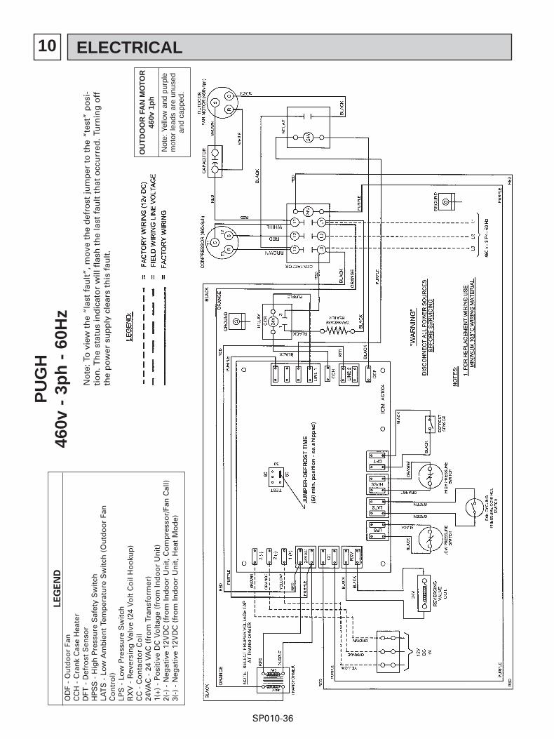
PU
GH
460v
- 3
ph
- 6
0Hz
No
te: T
o v
iew
th
e “l
ast
fau
lt”,
mo
ve t
he
def
rost
jum
per
to
th
e “t
est”
po
si-
tio
n. T
he
stat
us
ind
icat
or
will
fla
sh t
he
last
fau
lt t
hat
occ
urr
ed. T
urn
ing
off
the
po
wer
su
pp
ly c
lear
s th
is f
ault
.
LE
GE
ND
OD
F -
Ou
tdo
or
Fan
CC
H -
Cra
nk
Cas
e H
eate
rD
FT -
Def
rost
Sen
sor
HP
SS
- H
igh
Pre
ssu
re S
afet
y S
wit
chLA
TS
- L
ow
Am
bie
nt
Tem
per
atu
re S
wit
ch (
Ou
tdo
or
Fan
Co
ntr
ol)
LPS
- L
ow
Pre
ssu
re S
wit
chR
XV
- R
ever
sin
g V
alve
(24
Vo
lt C
oil
Ho
oku
p)
CC
- C
on
tact
or
Co
il24
VAC
- 2
4 VA
C (
fro
m T
ran
sfo
rmer
)1(
+) -
Po
siti
ve D
C V
olt
age
(fro
m In
do
or
Un
it)
2(-)
- N
egat
ive
12V
DC
(fr
om
Ind
oo
r U
nit
, Co
mp
ress
or/
Fan
Cal
l)3(
-) -
Neg
ativ
e 12
VD
C (
fro
m In
do
or
Un
it, H
eat
Mo
de)
OU
TD
OO
R F
AN
MO
TOR
460v
1p
h
Not
e: Y
ello
w a
nd p
urpl
e m
otor
lead
s ar
e un
used
an
d ca
pped
.
11 REFRIGERANT SYSTEM
SP010-37
A. PUG PIPING DIAGRAM
11 REFRIGERANT SYSTEM
SP010-38
B. PUGH HEAT PUMP MODELS
11 REFRIGERANT SYSTEM
SP010-39
SERVICE PORTSThere are 4 service ports available to service technicians. One port is located at each of the two “ball valves” and twoadditional ports are located directly above the ball valves. The purpose of each is:
A. Liquid Line Ball Valve Service Port. This port is used to evacuate the refrigerant line set when the ball valve is inthe closed position. It may also be used to measure the liquid line pressure or more accurately the “saturatedline” pressure during normal operation.
1) During cooling operation this service port is downstream of the metering orifice which is installed insideof the condensing unit. While in the cooling mode this pressure is typically 25 to 40 PSI above that of thesuction ball valve pressure (usually 85 to 110 PSI).
2) During heating operation this pressure continues to be downstream of the capillary tube which is nowmetering refrigerant at the outlet of the indoor unit.
B) Suction Ball Valve Service Port. This port is also used to evacuate the indoor unit and line set during installation(the ball valve must be closed to evacuate the line set and indoor unit). During normal cooling mode operationthis pressure port indicates evaporator pressure (minus line set pressure drop). Typical cooling mode pressurereadings here are in the range of 55 to 80 PSI during summer operation.
C) Two additional service ports are located directly above the ball valves. These ports are connected to the com-pressor discharge line and the suction line just above the accumulator. These ports always read “true” high andlow side pressures regardless of cooling or heating operating modes.
D. Both refrigerant lines must be insulated as a result of the “cooling side” metering device location (in outdoor
unit). Failure to insulate the liquid line, or more accurately the “saturation line”, will result in condensate drip-ping from the line and poor cooling performance.
E. Metering Devices. Metering of refrigerant in the cooling mode is accomplished by a “fixed orifice” that is locatedin the condensing unit. If a restriction or a compressor failure occurs this orifice can be easily accessed andcleaned after refrigerant is recovered.
12 PARTS BREAKDOWN
SP010-40
A. STRUCTURAL PARTS – ALL PUG AND PUG/H MODELS
No. Parts No. Parts Name Specifications
Q'ty/set
PUG/H18
1
2
3
4
5
6
7
8
9
10
11
12
13
14
15
501371FRP
501367FRP
501368FRP
501384FRP
537724FRP
537725FRP
501456FRP
818014FRP
501361FRP
501372FRP
537987FRP
501363FRP
501028FRP
501362FRP
537990FRP
PAINTED
PAINTED
PAINTED
PAINTED
GALVANIZED
GALVANIZED
PAINTED
ABS PLASTIC –BLACK
PAINTED
PAINTED
PAINTED
PAINTED
PAINTED
PAINTED
PAINTED
FRONT HOLD-DOWN/DECAL STRIP
COIL SEAL/CORNER PANEL
COIL SEAL/CORNER PANEL
BASE PANEL
RAIL – LONG
RAIL – SHORT
ACCESS DOOR
HANDLE
VERTICAL PANEL
REFRIGERATION LINE CLOSURE/MOUNTING PLATE
1
1
––––
1
1
1
1
1
1
1
1
1
1
1
1
PUG/H24
1
––––
1
1
1
1
1
1
1
1
1
1
1
1
1
PUG/H30
1
––––
1
1
1
1
1
1
1
1
1
1
1
1
1
PUG/H36
1
––––
1
1
1
1
1
1
1
1
1
1
1
1
1
PUG/H42
1
––––
1
1
1
1
1
1
1
1
1
1
1
1
1
BARRIER PLATE – LOWER W/BUSHINGS
CONTROL PANEL
CONTROL PANEL ACCESS COVER
COIL SEAL – LEFT
TOP
PUG/PUGH - ALL
12 PARTS BREAKDOWN
SP010-41
B. FUNCTIONAL PARTS – PUG-CKB PUG-CKC PUG-CKE MODELS
No. Parts No. Parts Name Specifications
Q'ty/set
PUG/H18CKB
1
2
4
5
6
7
8
9
10
11
12
3
416053FRP
416057FRP
416076FRP
416077FRP
416084FRP
416085FRP
416087FRP
255029FRP
255031FRP
255027FRP
416145FRP
416146FRP
416140FRP
416141FRP
416147FRP
416148FRP
416142FRP
416143FRP
507004FRP
507014FRP
FLOW CONTROL (3/8" I.D.)
FIELD CONNECTOR w/SWIVEL (3/8" I.D.)
RESTRICTOR
RESTRICTOR
RESTRICTOR
RESTRICTOR
RESTRICTOR
SERVICE VALVE – BODY
SERVICE VALVE – CORE
SERVICE VALVE – CAP
FLARE NUT (SMALL)
FLARE NUT (SMALL)
BASE VALVE – LIQUID
BASE VALVE – LIQUID
FLARE NUT (LARGE)
FLARE NUT (LARGE)
BASE VALVE – SUCTION
BASE VALVE – SUCTION
COMPRESSOR GROMMET
COMPRESSOR SLEEVE
1
1
1
––––
––––
––––
––––
2
2
2
1
––––
1
––––
1
––––
1
––––
4
4
.056" dia.
.058" dia.
.072" dia.
.074" dia.
.078" dia.
3/8"
1/2"
PUG/H24CKB
1
1
––––
1
––––
––––
––––
2
2
2
1
––––
1
––––
1
––––
1
––––
4
4
PUG/H30CKB
1
1
––––
––––
1
––––
––––
2
2
2
––––
1
––––
1
––––
1
––––
1
4
4
PUG/H36CKB
1
1
––––
––––
––––
1
––––
2
2
2
––––
1
––––
1
––––
1
––––
1
4
4
PUG/H42CKB
1
1
––––
––––
––––
––––
1
2
2
2
––––
1
––––
1
––––
1
––––
1
4
4
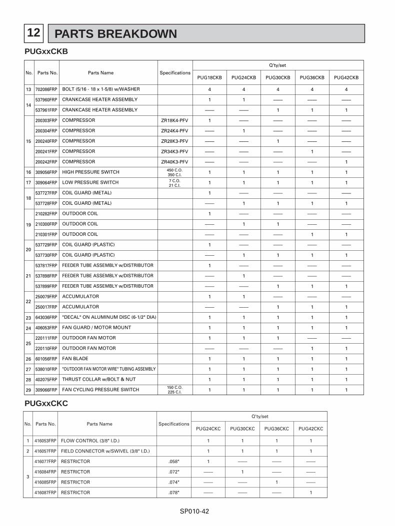
PUGxxCKB
12 PARTS BREAKDOWN
SP010-42
No. Parts No. Parts Name Specifications
Q'ty/set
PUG18CKB
14
15
18
19
20
21
25
26
27
28
29
22
23
24
16
17
13 702086FRP
537960FRP
537961FRP
200303FRP
200304FRP
200240FRP
200241FRP
200242FRP
309056FRP
309064FRP
537727FRP
537728FRP
210282FRP
210300FRP
210301FRP
537729FRP
537730FRP
537817FRP
537898FRP
537899FRP
250079FRP
250017FRP
643036FRP
406053FRP
220111FRP
220110FRP
601056FRP
538010FRP
402075FRP
309066FRP
BOLT (5/16 - 18 x 1-5/8) w/WASHER
CRANKCASE HEATER ASSEMBLY
CRANKCASE HEATER ASSEMBLY
COMPRESSOR
COMPRESSOR
COMPRESSOR
COMPRESSOR
COMPRESSOR
HIGH PRESSURE SWITCH
LOW PRESSURE SWITCH
COIL GUARD (METAL)
COIL GUARD (METAL)
OUTDOOR COIL
OUTDOOR COIL
OUTDOOR COIL
COIL GUARD (PLASTIC)
COIL GUARD (PLASTIC)
FEEDER TUBE ASSEMBLY w/DISTRIBUTOR
FEEDER TUBE ASSEMBLY w/DISTRIBUTOR
FEEDER TUBE ASSEMBLY w/DISTRIBUTOR
ACCUMULATOR
ACCUMULATOR
"DECAL" ON ALUMINUM DISC (6-1/2" DIA)
FAN GUARD / MOTOR MOUNT
OUTDOOR FAN MOTOR
OUTDOOR FAN MOTOR
FAN BLADE
"OUTDOOR FAN MOTOR WIRE" TUBING ASSEMBLY
THRUST COLLAR w/BOLT & NUT
FAN CYCLING PRESSURE SWITCH
4
1
––––
1
––––
––––
––––
––––
1
1
1
––––
1
––––
––––
1
––––
1
––––
––––
1
––––
1
1
1
––––
1
1
1
1
ZR18K4-PFV
ZR24K4-PFV
ZR28K3-PFV
ZR34K3-PFV
ZR40K3-PFV
450 C.O.350 C.I.
7 C.O.21 C.I.
150 C.O.225 C.I.
PUG24CKB
4
1
––––
––––
1
––––
––––
––––
1
1
––––
1
––––
1
––––
––––
1
––––
1
––––
1
––––
1
1
1
––––
1
1
1
1
PUG30CKB
4
––––
1
––––
––––
1
––––
––––
1
1
––––
1
––––
1
––––
––––
1
––––
––––
1
––––
1
1
1
1
––––
1
1
1
1
PUG36CKB
4
––––
1
––––
––––
––––
1
––––
1
1
––––
1
––––
––––
1
––––
1
––––
––––
1
––––
1
1
1
––––
1
1
1
1
1
PUG42CKB
4
––––
1
––––
––––
––––
––––
1
1
1
––––
1
––––
––––
1
––––
1
––––
––––
1
––––
1
1
1
––––
1
1
1
1
1
PUGxxCKB
PUGxxCKC
No. Parts No. Parts Name Specifications
Q'ty/set
1
2
3
416053FRP
416057FRP
416077FRP
416084FRP
416085FRP
416087FRP
FLOW CONTROL (3/8" I.D.)
FIELD CONNECTOR w/SWIVEL (3/8" I.D.)
RESTRICTOR
RESTRICTOR
RESTRICTOR
RESTRICTOR
PUG24CKC
1
1
1
––––
––––
––––
.058"
.072"
.074"
.078"
PUG30CKC
1
1
––––
1
––––
––––
PUG36CKC
1
1
––––
––––
1
––––
PUG42CKC
1
1
––––
––––
––––
1
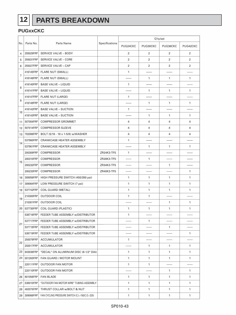
12 PARTS BREAKDOWN
SP010-43
No. Parts No. Parts Name Specifications
Q'ty/set
4
5
6
7
8
9
10
14
19
20
21
22
25
26
27
28
29
23
24
15
16
17
18
11
12
13
255029FRP
255031FRP
255027FRP
416145FRP
416146FRP
416140FRP
416141FRP
416147FRP
416148FRP
416142FRP
416143FRP
507004FRP
507014FRP
702086FRP
537960FRP
537961FRP
200309FRP
200310FRP
200232FRP
200233FRP
309056FRP
309064FRP
537742FRP
210300FRP
210301FRP
537730FRP
538716FRP
537717FRP
537718FRP
538719FRP
250079FRP
250017FRP
643036FRP
501263FRP
220111FRP
220110FRP
601056FRP
538010FRP
402075FRP
309066FRP
SERVICE VALVE – BODY
SERVICE VALVE – CORE
SERVICE VALVE – CAP
FLARE NUT (SMALL)
FLARE NUT (SMALL)
BASE VALVE – LIQUID
BASE VALVE – LIQUID
FLARE NUT (LARGE)
FLARE NUT (LARGE)
BASE VALVE – SUCTION
BASE VALVE – SUCTION
COMPRESSOR GROMMET
COMPRESSOR SLEEVE
BOLT (5/16 - 18 x 1-5/8) w/WASHER
CRANKCASE HEATER ASSEMBLY
CRANKCASE HEATER ASSEMBLY
COMPRESSOR
COMPRESSOR
COMPRESSOR
COMPRESSOR
HIGH PRESSURE SWITCH (450/350 psi)
LOW PRESSURE SWITCH (7 psi)
COIL GUARD (METAL)
OUTDOOR COIL
OUTDOOR COIL
COIL GUARD (PLASTIC)
FEEDER TUBE ASSEMBLY w/DISTRIBUTOR
FEEDER TUBE ASSEMBLY w/DISTRIBUTOR
FEEDER TUBE ASSEMBLY w/DISTRIBUTOR
FEEDER TUBE ASSEMBLY w/DISTRIBUTOR
ACCUMULATOR
ACCUMULATOR
"DECAL" ON ALUMINUM DISC (6-1/2" DIA)
FAN GUARD / MOTOR MOUNT
OUTDOOR FAN MOTOR
OUTDOOR FAN MOTOR
FAN BLADE
"OUTDOOR FAN MOTOR WIRE" TUBING ASSEMBLY
THRUST COLLAR w/BOLT & NUT
FAN CYCLING PRESSURE SWITCH (C.I.–150/C.O.–225)
PUG24CKC
2
2
2
1
––––
1
––––
1
––––
1
––––
4
4
4
1
––––
1
––––
––––
––––
1
1
1
1
––––
1
1
––––
––––
––––
1
––––
1
1
1
––––
1
1
1
1
ZR24K3-TF5
ZR28K3-TF5
ZR34K3-TF5
ZR40K3-TF5
PUG30CKC
2
2
2
––––
1
––––
1
––––
1
––––
1
4
4
4
––––
1
––––
1
––––
––––
1
1
1
1
––––
1
––––
1
––––
––––
––––
1
1
1
1
––––
1
1
1
1
PUG36CKC
2
2
2
––––
1
––––
1
––––
1
––––
1
4
4
4
––––
1
––––
––––
1
––––
1
1
1
––––
1
1
––––
––––
1
––––
––––
1
1
1
––––
1
1
1
1
1
PUG42CKC
2
2
2
––––
1
––––
1
––––
1
––––
1
4
4
4
––––
1
––––
––––
––––
1
1
1
1
––––
1
1
––––
––––
––––
1
––––
1
1
1
––––
1
1
1
1
1
PUGxxCKC
12 PARTS BREAKDOWN
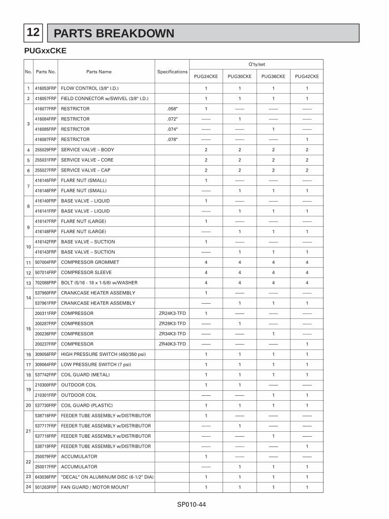
SP010-44
No. Parts No. Parts Name Specifications
Q'ty/set
1
2
3
416053FRP
416057FRP
416077FRP
416084FRP
416085FRP
416087FRP
FLOW CONTROL (3/8" I.D.)
FIELD CONNECTOR w/SWIVEL (3/8" I.D.)
RESTRICTOR
RESTRICTOR
RESTRICTOR
RESTRICTOR
PUG24CKE
1
1
1
––––
––––
––––
.058"
.072"
.074"
.078"
ZR24K3-TFD
ZR28K3-TFD
ZR34K3-TFD
ZR40K3-TFD
PUG30CKE
1
1
––––
1
––––
––––
PUG36CKE
1
1
––––
––––
1
––––
PUG42CKE
1
1
––––
––––
––––
1
4
5
6
7
8
9
10
14
19
20
21
22
23
24
15
16
17
18
11
12
13
255029FRP
255031FRP
255027FRP
416145FRP
416146FRP
416140FRP
416141FRP
416147FRP
416148FRP
416142FRP
416143FRP
507004FRP
507014FRP
702086FRP
537960FRP
537961FRP
200311FRP
200287FRP
200236FRP
200237FRP
309056FRP
309064FRP
537742FRP
210300FRP
210301FRP
537730FRP
538716FRP
537717FRP
537718FRP
538719FRP
250079FRP
250017FRP
643036FRP
501263FRP
SERVICE VALVE – BODY
SERVICE VALVE – CORE
SERVICE VALVE – CAP
FLARE NUT (SMALL)
FLARE NUT (SMALL)
BASE VALVE – LIQUID
BASE VALVE – LIQUID
FLARE NUT (LARGE)
FLARE NUT (LARGE)
BASE VALVE – SUCTION
BASE VALVE – SUCTION
COMPRESSOR GROMMET
COMPRESSOR SLEEVE
BOLT (5/16 - 18 x 1-5/8) w/WASHER
CRANKCASE HEATER ASSEMBLY
CRANKCASE HEATER ASSEMBLY
COMPRESSOR
COMPRESSOR
COMPRESSOR
COMPRESSOR
HIGH PRESSURE SWITCH (450/350 psi)
LOW PRESSURE SWITCH (7 psi)
COIL GUARD (METAL)
OUTDOOR COIL
OUTDOOR COIL
COIL GUARD (PLASTIC)
FEEDER TUBE ASSEMBLY w/DISTRIBUTOR
FEEDER TUBE ASSEMBLY w/DISTRIBUTOR
FEEDER TUBE ASSEMBLY w/DISTRIBUTOR
FEEDER TUBE ASSEMBLY w/DISTRIBUTOR
ACCUMULATOR
ACCUMULATOR
"DECAL" ON ALUMINUM DISC (6-1/2" DIA)
FAN GUARD / MOTOR MOUNT
2
2
2
1
––––
1
––––
1
––––
1
––––
4
4
4
1
––––
1
––––
––––
––––
1
1
1
1
––––
1
1
––––
––––
––––
1
––––
1
1
2
2
2
––––
1
––––
1
––––
1
––––
1
4
4
4
––––
1
––––
1
––––
––––
1
1
1
1
––––
1
––––
1
––––
––––
––––
1
1
1
2
2
2
––––
1
––––
1
––––
1
––––
1
4
4
4
––––
1
––––
––––
1
––––
1
1
1
––––
1
1
––––
––––
1
––––
––––
1
1
1
2
2
2
––––
1
––––
1
––––
1
––––
1
4
4
4
––––
1
––––
––––
––––
1
1
1
1
––––
1
1
––––
––––
––––
1
––––
1
1
1
PUGxxCKE
12 PARTS BREAKDOWN
SP010-45
No. Parts No. Parts Name Specifications
Q'ty/set
PUG24CKE PUG30CKE PUG36CKE PUG42CKE
25
26
27
28
29
220148FRP
220149FRP
601056FRP
538010FRP
402075FRP
309066FRP
OUTDOOR FAN MOTOR
OUTDOOR FAN MOTOR
FAN BLADE
"OUTDOOR FAN MOTOR WIRE" TUBING ASSEMBLY
THRUST COLLAR w/BOLT & NUT
FAN CYCLING PRESSURE SWITCH (C.I.–150/C.O.–225)
1
––––
1
1
1
1
1
––––
1
1
1
1
––––
1
1
1
1
1
––––
1
1
1
1
1
PUGxxCKE
12 PARTS BREAKDOWN
SP010-46
No. Parts No. Parts Name Specifications
Q'ty/set
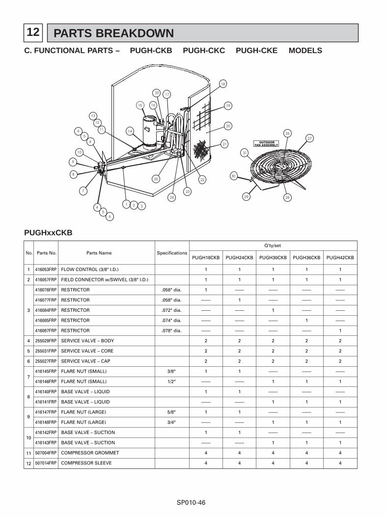
PUGH18CKB
1
2
4
5
6
7
8
9
10
11
12
3
416053FRP
416057FRP
416076FRP
416077FRP
416084FRP
416085FRP
416087FRP
255029FRP
255031FRP
255027FRP
416145FRP
416146FRP
416140FRP
416141FRP
416147FRP
416148FRP
416142FRP
416143FRP
507004FRP
507014FRP
FLOW CONTROL (3/8" I.D.)
FIELD CONNECTOR w/SWIVEL (3/8" I.D.)
RESTRICTOR
RESTRICTOR
RESTRICTOR
RESTRICTOR
RESTRICTOR
SERVICE VALVE – BODY
SERVICE VALVE – CORE
SERVICE VALVE – CAP
FLARE NUT (SMALL)
FLARE NUT (SMALL)
BASE VALVE – LIQUID
BASE VALVE – LIQUID
FLARE NUT (LARGE)
FLARE NUT (LARGE)
BASE VALVE – SUCTION
BASE VALVE – SUCTION
COMPRESSOR GROMMET
COMPRESSOR SLEEVE
1
1
1
––––
––––
––––
––––
2
2
2
1
––––
1
––––
1
––––
1
––––
4
4
.056" dia.
.058" dia.
.072" dia.
.074" dia.
.078" dia.
3/8"
1/2"
5/8"
3/4"
PUGH24CKB
1
1
––––
1
––––
––––
––––
2
2
2
1
––––
1
––––
1
––––
1
––––
4
4
PUGH30CKB
1
1
––––
––––
1
––––
––––
2
2
2
––––
1
––––
1
––––
1
––––
1
4
4
PUGH36CKB
1
1
––––
––––
––––
1
––––
2
2
2
––––
1
––––
1
––––
1
––––
1
4
4
PUGH42CKB
1
1
––––
––––
––––
––––
1
2
2
2
––––
1
––––
1
––––
1
––––
1
4
4
C. FUNCTIONAL PARTS – PUGH-CKB PUGH-CKC PUGH-CKE MODELS
PUGHxxCKB
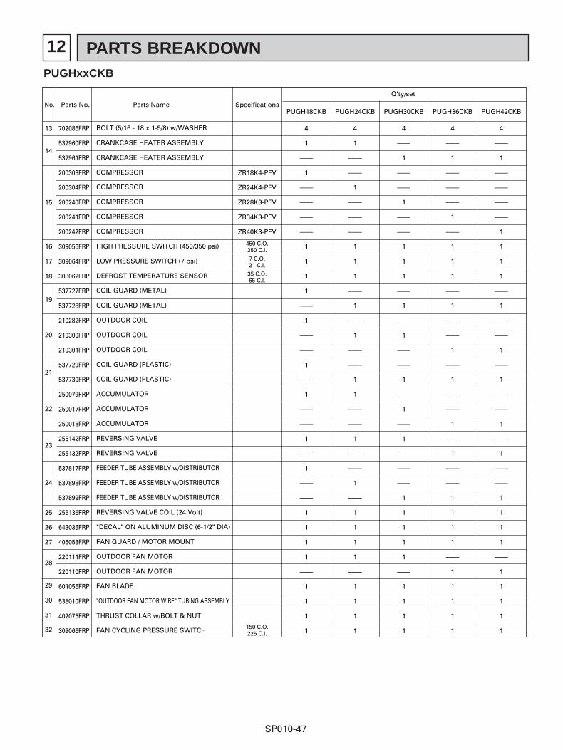
12 PARTS BREAKDOWN
SP010-47
No. Parts No. Parts Name Specifications
Q'ty/set
PUGH18CKB
14
15
18
19
20
21
24
25
26
27
28
29
30
31
32
22
23
16
17
13 702086FRP
537960FRP
537961FRP
200303FRP
200304FRP
200240FRP
200241FRP
200242FRP
309056FRP
309064FRP
308062FRP
537727FRP
537728FRP
210282FRP
210300FRP
210301FRP
537729FRP
537730FRP
250079FRP
250017FRP
250018FRP
255142FRP
255132FRP
537817FRP
537898FRP
537899FRP
255136FRP
643036FRP
406053FRP
220111FRP
220110FRP
601056FRP
538010FRP
402075FRP
309066FRP
BOLT (5/16 - 18 x 1-5/8) w/WASHER
CRANKCASE HEATER ASSEMBLY
CRANKCASE HEATER ASSEMBLY
COMPRESSOR
COMPRESSOR
COMPRESSOR
COMPRESSOR
COMPRESSOR
HIGH PRESSURE SWITCH (450/350 psi)
LOW PRESSURE SWITCH (7 psi)
DEFROST TEMPERATURE SENSOR
COIL GUARD (METAL)
COIL GUARD (METAL)
OUTDOOR COIL
OUTDOOR COIL
OUTDOOR COIL
COIL GUARD (PLASTIC)
COIL GUARD (PLASTIC)
ACCUMULATOR
ACCUMULATOR
ACCUMULATOR
REVERSING VALVE
REVERSING VALVE
FEEDER TUBE ASSEMBLY w/DISTRIBUTOR
FEEDER TUBE ASSEMBLY w/DISTRIBUTOR
FEEDER TUBE ASSEMBLY w/DISTRIBUTOR
REVERSING VALVE COIL (24 Volt)
"DECAL" ON ALUMINUM DISC (6-1/2" DIA)
FAN GUARD / MOTOR MOUNT
OUTDOOR FAN MOTOR
OUTDOOR FAN MOTOR
FAN BLADE
"OUTDOOR FAN MOTOR WIRE" TUBING ASSEMBLY
THRUST COLLAR w/BOLT & NUT
FAN CYCLING PRESSURE SWITCH
4
1
––––
1
––––
––––
––––
––––
1
1
1
1
––––
1
––––
––––
1
––––
1
––––
––––
1
––––
1
––––
––––
1
1
1
1
––––
1
1
1
1
ZR18K4-PFV
ZR24K4-PFV
ZR28K3-PFV
ZR34K3-PFV
ZR40K3-PFV
450 C.O.350 C.I.
7 C.O.21 C.I.
35 C.O.65 C.I.
150 C.O.225 C.I.
PUGH24CKB
4
1
––––
––––
1
––––
––––
––––
1
1
1
––––
1
––––
1
––––
––––
1
1
––––
––––
1
––––
––––
1
––––
1
1
1
1
––––
1
1
1
1
PUGH30CKB
4
––––
1
––––
––––
1
––––
––––
1
1
1
––––
1
––––
1
––––
––––
1
––––
1
––––
1
––––
––––
––––
1
1
1
1
1
––––
1
1
1
1
PUGH36CKB
4
––––
1
––––
––––
––––
1
––––
1
1
1
––––
1
––––
––––
1
––––
1
––––
––––
1
––––
1
––––
––––
1
1
1
1
––––
1
1
1
1
1
PUGH42CKB
4
––––
1
––––
––––
––––
––––
1
1
1
1
––––
1
––––
––––
1
––––
1
––––
––––
1
––––
1
––––
––––
1
1
1
1
––––
1
1
1
1
1
PUGHxxCKB
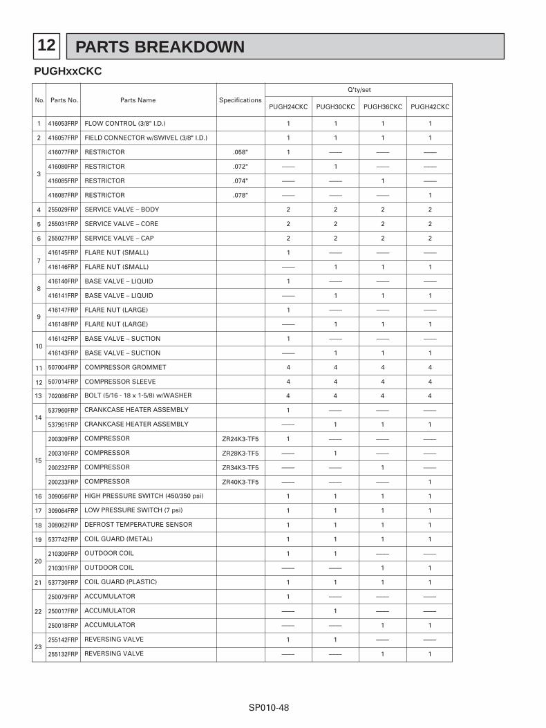
12 PARTS BREAKDOWN
SP010-48
No. Parts No. Parts Name Specifications
Q'ty/set
1
2
4
5
6
7
8
9
10
11
12
3
416053FRP
416057FRP
416077FRP
416080FRP
416085FRP
416087FRP
255029FRP
255031FRP
255027FRP
416145FRP
416146FRP
416140FRP
416141FRP
416147FRP
416148FRP
416142FRP
416143FRP
507004FRP
507014FRP
702086FRP
537960FRP
537961FRP
200309FRP
200310FRP
200232FRP
200233FRP
309056FRP
309064FRP
308062FRP
537742FRP
210300FRP
210301FRP
537730FRP
250079FRP
250017FRP
250018FRP
255142FRP
255132FRP
FLOW CONTROL (3/8" I.D.)
FIELD CONNECTOR w/SWIVEL (3/8" I.D.)
RESTRICTOR
RESTRICTOR
RESTRICTOR
RESTRICTOR
SERVICE VALVE – BODY
SERVICE VALVE – CORE
SERVICE VALVE – CAP
FLARE NUT (SMALL)
FLARE NUT (SMALL)
BASE VALVE – LIQUID
BASE VALVE – LIQUID
FLARE NUT (LARGE)
FLARE NUT (LARGE)
BASE VALVE – SUCTION
BASE VALVE – SUCTION
COMPRESSOR GROMMET
COMPRESSOR SLEEVE
PUGH24CKC
1
1
1
––––
––––
––––
2
2
2
1
––––
1
––––
1
––––
1
––––
4
4
.058"
.072"
.074"
.078"
ZR24K3-TF5
ZR28K3-TF5
ZR34K3-TF5
ZR40K3-TF5
PUGH30CKC
1
1
––––
1
––––
––––
2
2
2
––––
1
––––
1
––––
1
––––
1
4
4
PUGH36CKC
1
1
––––
––––
1
––––
2
2
2
––––
1
––––
1
––––
1
––––
1
4
4
PUGH42CKC
1
1
––––
––––
––––
1
2
2
2
––––
1
––––
1
––––
1
––––
1
4
4
14
15
18
19
20
21
22
23
16
17
13 BOLT (5/16 - 18 x 1-5/8) w/WASHER
CRANKCASE HEATER ASSEMBLY
CRANKCASE HEATER ASSEMBLY
COMPRESSOR
COMPRESSOR
COMPRESSOR
COMPRESSOR
HIGH PRESSURE SWITCH (450/350 psi)
LOW PRESSURE SWITCH (7 psi)
DEFROST TEMPERATURE SENSOR
COIL GUARD (METAL)
OUTDOOR COIL
OUTDOOR COIL
COIL GUARD (PLASTIC)
ACCUMULATOR
ACCUMULATOR
ACCUMULATOR
REVERSING VALVE
REVERSING VALVE
4
1
––––
1
––––
––––
––––
1
1
1
1
1
––––
1
1
––––
––––
1
––––
4
––––
1
––––
1
––––
––––
1
1
1
1
1
––––
1
––––
1
––––
1
––––
4
––––
1
––––
––––
1
––––
1
1
1
1
––––
1
1
––––
––––
1
––––
1
4
––––
1
––––
––––
––––
1
1
1
1
1
––––
1
1
––––
––––
1
––––
1
PUGHxxCKC
12 PARTS BREAKDOWN
SP010-49
No. Parts No. Parts Name Specifications
Q'ty/set
538716FRP
538717FRP
538718FRP
538719FRP
255136FRP
643036FRP
501263FRP
220111FRP
220110FRP
601056FRP
538010FRP
402075FRP
309066FRP
PUGH24CKC PUGH30CKC PUGH36CKC PUGH42CKC
24
25
26
27
28
29
30
31
32
FEEDER TUBE ASSEMBLY w/DISTRIBUTOR
FEEDER TUBE ASSEMBLY w/DISTRIBUTOR
FEEDER TUBE ASSEMBLY w/DISTRIBUTOR
FEEDER TUBE ASSEMBLY w/DISTRIBUTOR
REVERSING VALVE COIL (24 Volt)
"DECAL" ON ALUMINUM DISC (6-1/2" DIA)
FAN GUARD / MOTOR MOUNT
OUTDOOR FAN MOTOR
OUTDOOR FAN MOTOR
FAN BLADE
"OUTDOOR FAN MOTOR WIRE" TUBING ASSEMBLY
THRUST COLLAR w/BOLT & NUT
FAN CYCLING PRESSURE SWITCH (C.I.–150/C.O.–225)
1
––––
––––
––––
1
1
1
1
––––
1
1
1
1
––––
1
––––
––––
1
1
1
1
––––
1
1
1
1
––––
––––
1
––––
1
1
1
––––
1
1
1
1
1
––––
––––
––––
1
1
1
1
––––
1
1
1
1
1
PUGHxxCKC
No. Parts No. Parts Name Specifications
Q'ty/set
1
2
4
5
6
7
8
9
10
11
12
3
416053FRP
416057FRP
416077FRP
416080FRP
416085FRP
416087FRP
255029FRP
255031FRP
255027FRP
416145FRP
416146FRP
416140FRP
416141FRP
416147FRP
416148FRP
416142FRP
416143FRP
507004FRP
507014FRP
702086FRP
537960FRP
537961FRP
FLOW CONTROL (3/8" I.D.)
FIELD CONNECTOR w/SWIVEL (3/8" I.D.)
RESTRICTOR
RESTRICTOR
RESTRICTOR
RESTRICTOR
SERVICE VALVE – BODY
SERVICE VALVE – CORE
SERVICE VALVE – CAP
FLARE NUT (SMALL)
FLARE NUT (SMALL)
BASE VALVE – LIQUID
BASE VALVE – LIQUID
FLARE NUT (LARGE)
FLARE NUT (LARGE)
BASE VALVE – SUCTION
BASE VALVE – SUCTION
COMPRESSOR GROMMET
COMPRESSOR SLEEVE
PUGH24CKE
1
1
1
––––
––––
––––
2
2
2
1
––––
1
––––
1
––––
1
––––
4
4
.058"
.072"
.074"
.078"
PUGH30CKE
1
1
––––
1
––––
––––
2
2
2
––––
1
––––
1
––––
1
––––
1
4
4
PUGH36CKE
1
1
––––
––––
1
––––
2
2
2
––––
1
––––
1
––––
1
––––
1
4
4
PUGH42CKE
1
1
––––
––––
––––
1
2
2
2
––––
1
––––
1
––––
1
––––
1
4
4
14
13 BOLT (5/16 - 18 x 1-5/8) w/WASHER
CRANKCASE HEATER ASSEMBLY
CRANKCASE HEATER ASSEMBLY
4
1
––––
4
––––
1
4
––––
1
4
––––
1
PUGHxxCKE
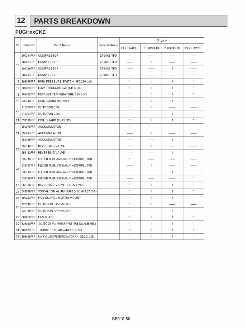
12 PARTS BREAKDOWN
SP010-50
No. Parts No. Parts Name Specifications
Q'ty/set
200311FRP
200287FRP
200236FRP
200237FRP
309056FRP
309064FRP
308062FRP
537742FRP
210300FRP
210301FRP
537730FRP
250079FRP
250017FRP
250018FRP
255142FRP
255132FRP
538716FRP
538717FRP
538718FRP
538719FRP
255136FRP
643036FRP
501263FRP
220149FRP
220148FRP
601056FRP
538010FRP
402075FRP
309066FRP
PUGH24CKE PUGH30CKE PUGH36CKE PUGH42CKE
15
18
19
20
21
24
25
26
27
28
29
30
31
32
22
23
16
17
COMPRESSOR
COMPRESSOR
COMPRESSOR
COMPRESSOR
HIGH PRESSURE SWITCH (450/350 psi)
LOW PRESSURE SWITCH (7 psi)
DEFROST TEMPERATURE SENSOR
COIL GUARD (METAL)
OUTDOOR COIL
OUTDOOR COIL
COIL GUARD (PLASTIC)
ACCUMULATOR
ACCUMULATOR
ACCUMULATOR
REVERSING VALVE
REVERSING VALVE
FEEDER TUBE ASSEMBLY w/DISTRIBUTOR
FEEDER TUBE ASSEMBLY w/DISTRIBUTOR
FEEDER TUBE ASSEMBLY w/DISTRIBUTOR
FEEDER TUBE ASSEMBLY w/DISTRIBUTOR
REVERSING VALVE COIL (24 Volt)
"DECAL" ON ALUMINUM DISC (6-1/2" DIA)
FAN GUARD / MOTOR MOUNT
OUTDOOR FAN MOTOR
OUTDOOR FAN MOTOR
FAN BLADE
"OUTDOOR FAN MOTOR WIRE" TUBING ASSEMBLY
THRUST COLLAR w/BOLT & NUT
FAN CYCLING PRESSURE SWITCH (C.I.–150/C.O.–225)
1
––––
––––
––––
1
1
1
1
1
––––
1
1
––––
––––
1
––––
1
––––
––––
––––
1
1
1
1
––––
1
1
1
1
ZR24K3-TFD
ZR28K3-TFD
ZR34K3-TFD
ZR40K3-TFD
––––
1
––––
––––
1
1
1
1
1
––––
1
––––
1
––––
1
––––
––––
1
––––
––––
1
1
1
1
––––
1
1
1
1
––––
––––
1
––––
1
1
1
1
––––
1
1
––––
––––
1
––––
1
––––
––––
1
––––
1
1
1
––––
1
1
1
1
1
––––
––––
––––
1
1
1
1
1
––––
1
1
––––
––––
1
––––
1
––––
––––
––––
1
1
1
1
––––
1
1
1
1
1
PUGHxxCKE
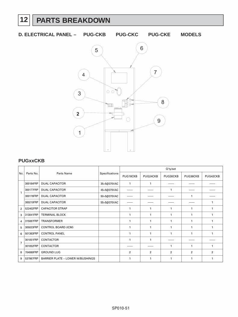
12 PARTS BREAKDOWN
SP010-51
D. ELECTRICAL PANEL – PUG-CKB PUG-CKC PUG-CKE MODELS
No. Parts No. Parts Name Specifications
Q'ty/set
PUG18CKB
1
7
2
3
4
5
6
8
9
300184FRP
300177FRP
300176FRP
300210FRP
522402FRP
313041FRP
315067FRP
305023FRP
501363FRP
301051FRP
301052FRP
704060FRP
537987FRP
DUAL CAPACITOR
DUAL CAPACITOR
DUAL CAPACITOR
DUAL CAPACITOR
CAPACITOR STRAP
TERMINAL BLOCK
TRANSFORMER
CONTROL BOARD (ICM)
CONTROL PANEL
CONTACTOR
CONTACTOR
GROUND LUG
BARRIER PLATE – LOWER W/BUSHINGS
1
––––
––––
––––
1
1
1
1
1
1
––––
2
1
PUG24CKB
1
––––
––––
––––
1
1
1
1
1
1
––––
2
1
PUG30CKB
––––
1
––––
––––
1
1
1
1
1
––––
1
2
1
PUG36CKB
––––
––––
1
––––
1
1
1
1
1
––––
1
2
1
PUG42CKB
––––
––––
––––
1
1
1
1
1
1
––––
1
2
1
35+5@370VAC
45+5@370VAC
50+5@370VAC
55+5@370VAC
PUGxxCKB
12 PARTS BREAKDOWN
SP010-52
No. Parts No. Parts Name Specifications
Q'ty/set
1
2
3
4
5
6
7
8
9
300179FRP
522402FRP
313041FRP
315067FRP
305023FRP
501363FRP
301047FRP
704060FRP
537987FRP
CAPACITOR
CAPACITOR STRAP
TERMINAL BLOCK
TRANSFORMER
CONTROL BOARD (ICM)
CONTROL PANEL
CONTACTOR
GROUND LUG
BARRIER PLATE – LOWER W/BUSHINGS
PUG24CKC
1
1
1
1
1
1
1
2
1
PUG30CKC
1
1
1
1
1
1
1
2
1
PUG36CKC
1
1
1
1
1
1
1
2
1
PUG42CKC
1
1
1
1
1
1
1
2
1
PUGxxCKC
No. Parts No. Parts Name Specifications
Q'ty/set
1
2
3
4
5
6
7
8
9
300179FRP
522402FRP
313040FRP
315067FRP
305023FRP
501363FRP
301047FRP
704060FRP
537987FRP
CAPACITOR
CAPACITOR STRAP
TERMINAL BLOCK
TRANSFORMER
CONTROL BOARD (ICM)
CONTROL PANEL
CONTACTOR
GROUND LUG
BARRIER PLATE – LOWER W/BUSHINGS
PUGH24CKE
1
1
1
1
1
1
1
2
1
PUGH30CKE
1
1
1
1
1
1
1
2
1
PUGH36CKE
1
1
1
1
1
1
1
2
1
PUGH42CKE
1
1
1
1
1
1
1
2
1
PUGxxCKE
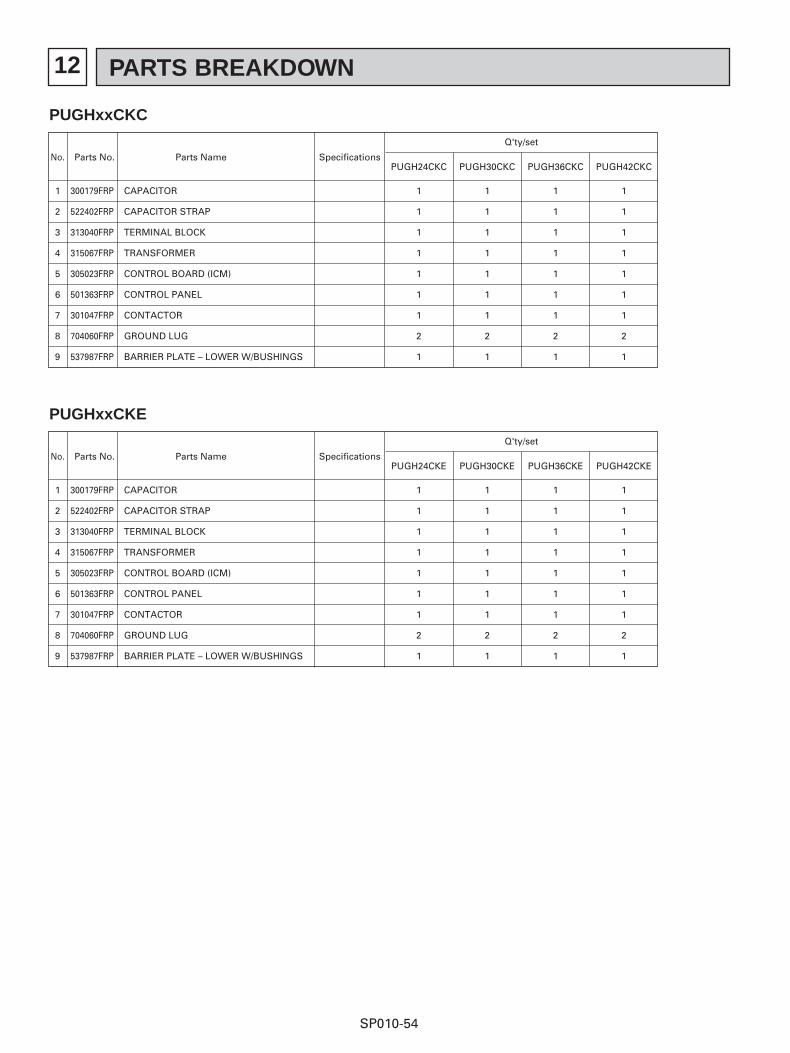
12 PARTS BREAKDOWN
SP010-53
No. Parts No. Parts Name Specifications
Q'ty/set
PUGH18CKB
1
7
2
3
4
5
6
8
9
300184FRP
300177FRP
300176FRP
300210FRP
522402FRP
313040FRP
315067FRP
305023FRP
501363FRP
301051FRP
301052FRP
704060FRP
537987FRP
DUAL CAPACITOR
DUAL CAPACITOR
DUAL CAPACITOR
DUAL CAPACITOR
CAPACITOR STRAP
TERMINAL BLOCK
TRANSFORMER
CONTROL BOARD (ICM)
CONTROL PANEL
CONTACTOR
CONTACTOR
GROUND LUG
BARRIER PLATE – LOWER W/BUSHINGS
1
––––
––––
––––
1
1
1
1
1
1
––––
2
1
PUGH24CKB
1
––––
––––
––––
1
1
1
1
1
1
––––
2
1
PUGH30CKB
––––
1
––––
––––
1
1
1
1
1
––––
1
2
1
PUGH36CKB
––––
––––
1
––––
1
1
1
1
1
––––
1
2
1
PUGH42CKB
––––
––––
––––
1
1
1
1
1
1
––––
1
2
1
35+5@370VAC
45+5@370VAC
50+5@370VAC
55+5@370VAC
E. ELECTRICAL PANEL – PUGH-CKB PUGH-CKC PUGH-CKE MODELS
PUGHxxCKB
12 PARTS BREAKDOWN
SP010-54
No. Parts No. Parts Name Specifications
Q'ty/set
1
2
3
4
5
6
7
8
9
300179FRP
522402FRP
313040FRP
315067FRP
305023FRP
501363FRP
301047FRP
704060FRP
537987FRP
CAPACITOR
CAPACITOR STRAP
TERMINAL BLOCK
TRANSFORMER
CONTROL BOARD (ICM)
CONTROL PANEL
CONTACTOR
GROUND LUG
BARRIER PLATE – LOWER W/BUSHINGS
PUGH24CKC
1
1
1
1
1
1
1
2
1
PUGH30CKC
1
1
1
1
1
1
1
2
1
PUGH36CKC
1
1
1
1
1
1
1
2
1
PUGH42CKC
1
1
1
1
1
1
1
2
1
PUGHxxCKC
No. Parts No. Parts Name Specifications
Q'ty/set
1
2
3
4
5
6
7
8
9
300179FRP
522402FRP
313040FRP
315067FRP
305023FRP
501363FRP
301047FRP
704060FRP
537987FRP
CAPACITOR
CAPACITOR STRAP
TERMINAL BLOCK
TRANSFORMER
CONTROL BOARD (ICM)
CONTROL PANEL
CONTACTOR
GROUND LUG
BARRIER PLATE – LOWER W/BUSHINGS
PUGH24CKE
1
1
1
1
1
1
1
2
1
PUGH30CKE
1
1
1
1
1
1
1
2
1
PUGH36CKE
1
1
1
1
1
1
1
2
1
PUGH42CKE
1
1
1
1
1
1
1
2
1
PUGHxxCKE
SP010Printed in Atlanta, GA 2.5M 9/02
New Publication Effective August 2002.Specifications subject to change without notice.