SPOOCEFEM: The Simplified Parallel Object-Oriented Computing Environment for the Finite Element Method With Application: Liquid Composite Molding by Brian J. Henz and Dale R. Shires ARL-TR-3115 December 2003 Approved for public release; distribution is unlimited.
Transcript
SPOOCEFEM: The Simplified Parallel Object-Oriented Computing Environment for the Finite Element Method
With Application: Liquid Composite Molding
by Brian J. Henz and Dale R. Shires
ARL-TR-3115 December 2003
Approved for public release; distribution is unlimited.
NOTICES
Disclaimers The findings in this report are not to be construed as an official Department of the Army position unless so designated by other authorized documents. Citation of manufacturer’s or trade names does not constitute an official endorsement or approval of the use thereof. Destroy this report when it is no longer needed. Do not return it to the originator.
Army Research Laboratory Aberdeen Proving Ground, MD 21005-5067
ARL-TR-3115 December 2003
SPOOCEFEM: The Simplified Parallel Object-Oriented Computing Environment for the Finite Element Method
With Application: Liquid Composite Molding
Brian J. Henz and Dale R. Shires Computational and Information Sciences Directorate, ARL
Approved for public release; distribution is unlimited.
ii
Report Documentation Page Form Approved OMB No. 0704-0188
Public reporting burden for this collection of information is estimated to average 1 hour per response, including the time for reviewing instructions, searching existing data sources, gathering and maintaining the data needed, and completing and reviewing the collection information. Send comments regarding this burden estimate or any other aspect of this collection of information, including suggestions for reducing the burden, to Department of Defense, Washington Headquarters Services, Directorate for Information Operations and Reports (0704-0188), 1215 Jefferson Davis Highway, Suite 1204, Arlington, VA 22202-4302. Respondents should be aware that notwithstanding any other provision of law, no person shall be subject to any penalty for failing to comply with a collection of information if it does not display a currently valid OMB control number. PLEASE DO NOT RETURN YOUR FORM TO THE ABOVE ADDRESS. 1. REPORT DATE (DD-MM-YYYY)
December 2003 2. REPORT TYPE
Final 3. DATES COVERED (From - To)
March 2003–June 2003 5a. CONTRACT NUMBER
5b. GRANT NUMBER
4. TITLE AND SUBTITLE
SPOOCEFEM: The Simplified Parallel Object-Oriented Computing Environment for the Finite Element Method With Application: Liquid Composite Molding
5c. PROGRAM ELEMENT NUMBER
5d. PROJECT NUMBER
3U21CL 5e. TASK NUMBER
6. AUTHOR(S)
Brian J. Henz and Dale R. Shires
5f. WORK UNIT NUMBER
7. PERFORMING ORGANIZATION NAME(S) AND ADDRESS(ES)
U.S. Army Research Laboratory ATTN: AMSRD-ARL-CI-HC Aberdeen Proving Ground, MD 21005-5067
8. PERFORMING ORGANIZATION REPORT NUMBER
ARL-TR-3115
10. SPONSOR/MONITOR'S ACRONYM(S)
9. SPONSORING/MONITORING AGENCY NAME(S) AND ADDRESS(ES)
11. SPONSOR/MONITOR'S REPORT NUMBER(S)
12. DISTRIBUTION/AVAILABILITY STATEMENT
Approved for public release; distribution is unlimited.
13. SUPPLEMENTARY NOTES
14. ABSTRACT
The use of object-oriented programming techniques in development of parallel, finite element analysis software enhances software reused and makes application development more efficient. In this report, an object-oriented programming framework for developing parallel finite element software is described. All required steps, from date file parsing and equation solving to post processing and graphical user interfaces, are discussed. After development of the framework, a sample parallel finite element code, namely COMPOSE, is extracted from its original functional programming paradigm and implemented in the new object-oriented programming framework. Besides ease of development, the use of generic visualization and interface tools for software using the framework speeds delivery of research codes to end users.
15. SUBJECT TERMS
object-oriented programming, parallel processing, finite element method, resin transfer molding, software development
16. SECURITY CLASSIFICATION OF: 19a. NAME OF RESPONSIBLE PERSON Brain J. Henz
a. REPORT UNCLASSIFIED
b. ABSTRACT UNCLASSIFIED
c. THIS PAGE UNCLASSIFIED
17. LIMITATION OF ABSTRACT
UL
18. NUMBER OF PAGES
30 19b. TELEPHONE NUMBER (Include area code)
410-278-6531 Standard Form 298 (Rev. 8/98) Prescribed by ANSI Std. Z39.18
iii
Contents
List of Figures iv
List of Tables iv
Acknowledgments v
1. Introduction 1
2. SPOOCEFEM Goals and Implementation 2
3. SPOOCEFEM Structure 3 3.1 The FEM Data File Format .............................................................................................4
3.2 NASTRAN and PATRAN Neutral Format Parsers/Converters......................................6
3.3 The Finite Element Class ................................................................................................6
3.4 The Helper Classes..........................................................................................................7
4. SPOOCEFEM Parallel Extensions 8 4.1 The Finite Element Class ................................................................................................8
4.2 The Vector and Matrix Classes .......................................................................................8
5. Application Development With the SPOOCEFEM Framework 10 5.1 Problem Description......................................................................................................10
5.2 Application-Specific FEM Code ...................................................................................11
5.3 Performance Comparison Between Structured and OOP-Based COMPOSE Software.........................................................................................................................13
6. Conclusions 17
7. Future Development 17
8. References 18
Distribution List 20
iv
List of Figures
Figure 1. SPOOCEFEM building block framework.......................................................................3 Figure 2. Hierarchy of the FEM object used by all applications. ...................................................7 Figure 3. Comparison of solution times for linear system of equations from COMPOSE. .........10 Figure 4. Hierarchy of the ComposeElement2dTri3 class showing multiple inheritances...........12 Figure 5. Results of PSPASES vs. COMPOSE comparison. .......................................................16
List of Tables
Table 1. Simulation time in seconds for 105,722 node RTM simulation. ....................................14 Table 2. Speedup results for 105,722 node RTM simulation, assuming perfect speedup at
eight processors........................................................................................................................14 Table 3. Simulation time in seconds for 425,156 node RTM simulation. ....................................15 Table 4. Speedup results for 425,156 node RTM simulation, assuming perfect speedup at
eight processors........................................................................................................................15 Table 5. Simulation time in seconds for 105,722 node RTM simulation with full range of
material properties. ..................................................................................................................15 Table 6. Simulation time in seconds for 425,156 node RTM simulation with full range of
material properties. ..................................................................................................................15
v
Acknowledgments
This research was made possible by a grant of computer time and resources by the Department of Defense High Performance Computing Modernization Program. Parallel versions of COMPOSE were developed through support from the Common High Performance Computing Software Support Initiative project.
vi
INTENTIONALLY LEFT BLANK.
1
1. Introduction
Scientific computing has provided insights and solutions for numerous classes of scientific and engineering problems. Computational science, the techniques used to arrive at these solutions, requires effective use of computer hardware systems and algorithm development strategies. While these problems can often be computed on a single processor, most often the sheer complexity and size of the problem in question requires the use of parallel computer systems. One of the predominant uses of the many large-scale, parallel computer systems in use today is for the solution of problems in science and engineering. Indeed, the performance of these systems is most often measured by its speed at solving mathematically oriented benchmark applications.
While great strides have continually been made in hardware and parallel processing speed, software development for these applications remains problematic. The focus on code execution speed combined with early formal language theory to create simple, easy to compile, function-oriented design languages like FORTRAN 77. These early languages had limited features and could generate machine code as efficient as the best hand-coded routines. Since these early days, languages such as C and extensions to FORTRAN, including FORTRAN 90/95 and High Performance FORTRAN, continue to provide more robust functionality. Today, C and FORTRAN remain the predominant languages of choice for scientific computing codes.
However, these languages suffer common function-oriented design problems. They do not provide for effective code reuse. Most often, this requires copying and modifying code from an existing application to a new application. This inevitably introduces unwanted side effects and buggy code. It also means that the substantial effort already employed to produce viable, efficient code is limited to the current application only. The lack of modularity is also a problem. An operation on data in these codes can often be spread over multiple functions with no clear entry and exit point. This data abstraction, the definition of new data types, and associated functionality is a crucial component that holds the key to resolving many of these problems. It is no surprise that as the FORTRAN language has continued to evolve; this support has been incorporated into FORTRAN 90/95 (Ellis et al., 1994).
Object-oriented design and the related object-oriented programming (OOP) is an approach widely offered in place of function-oriented design. It is based on information hiding and focuses on the software system as a set of interconnected, interfacing objects (Sommerville, 1989). Information hiding forces the developments to be modular and allows for built-up systems of components. This promotes software reuse and allows for selective optimization.
2
These concepts, however, have not been widely applied to scientific computing codes. In this report, we focus on applying these techniques to the finite element method (FEM). The FEM is a technique found in computational engineering that has been used in various serial and parallel codes.
While the use of OOP is not widespread in computational engineering, it has been applied successfully in certain instances (Ford et al., 1990; Mackie, 1992; Sun and Marrero, 1998). Some parallel OOP formulations for the FEM have also been introduced (Modak and Sotelino, 2002; Niekamp and Stein, 2002). These developments focus our current research and extensions to make the approach more generic and robust. The new toolkit described in this chapter is called SPOOCEFEM (Simple Parallel Object-Oriented Computing Environment for the Finite Element Method). The framework has been designed to allow for extensive software reuse, describe common data file representations to promote interfacing with multidisciplinary codes and scientific visualization packages, and provide functionality on both single and multiprocessor architectures.
2. SPOOCEFEM Goals and Implementation
While there really is no easy way to iterate the goals behind a development effort (usually there are just too many), several in this case are worth noting. The first design goal for SPOOCEFEM was that it be generic. By providing a general OOP FEM framework, new application codes are spared the tedious and laborious effort required to replicate much of the functionality that is common across the various FEM codes. For example, various finite element types are supported with associated routines, such as computation and storage of local coordinates.
The second goal was that it be modular. Base classes with well-defined interfaces are constructed first. More complex objects, such as an FEM object, are composed of these base classes. In a current application using SPOOCEFEM, this practice has allowed for the creation of complex classes using multiple inheritances with no requirements for revisiting the base code. This modularity, even to the level of the input and output data, has allowed it to be easily interfaced with existing scientific visualization codes. The result is a solution built from well-tested components complete with interfaces to complex scientific visualization libraries.
Speed was the final goal in the development of the library. This is an active research area for the SPOOCEFEM developers as the library is still being profiled and studied for performance. Of primary note, however, is that the modularity of the design has allowed for a system where numerical solvers can easily be selected and changed according to the needs of a specific FEM application. As with numerous scientific computing codes, the majority of the times we have seen in codes using SPOOCEFEM require the solution of linear systems of equations. The
3
modularity of the developments foster speed by making these changes virtually effortless, as compared to the colossal effort required to change embedded solvers in functional programming codes. Even if the runtime system required to support operator overloading and polymorphism incurs some overhead compared to historical codes such as those developed with FORTRAN, we feel the reduced time to solution in the development cycle is worth the slight increase in computer time.
The language of choice for these developments is C++. The authors have had success in porting the newly developed library using this standardized language coupled with the MPI libraries for parallel execution. The current ports include the SGI Origin machines, Linux clusters, and the IBM SP3 and SP4. It should be noted, however, that these benefits do come at a price. The initial ramp-up time to a fully functioning SPOOCEFEM library was significant. However, the authors are already taking advantage of the functionality provided by the library in quickly extending and developing new codes based on the FEM.
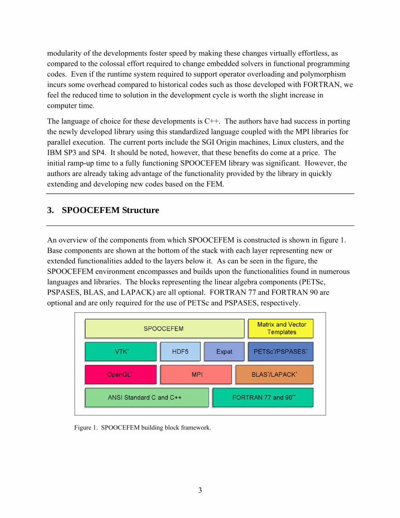
3. SPOOCEFEM Structure
An overview of the components from which SPOOCEFEM is constructed is shown in figure 1. Base components are shown at the bottom of the stack with each layer representing new or extended functionalities added to the layers below it. As can be seen in the figure, the SPOOCEFEM environment encompasses and builds upon the functionalities found in numerous languages and libraries. The blocks representing the linear algebra components (PETSc, PSPASES, BLAS, and LAPACK) are all optional. FORTRAN 77 and FORTRAN 90 are optional and are only required for the use of PETSc and PSPASES, respectively.
Figure 1. SPOOCEFEM building block framework.
4
The remainder of the report is devoted to a discussion of the integration of these various components and the functionalities found at the SPOOCEFEM layer. In particular, this section includes discussions of the data format used in SPOOCEFEM, some of the classes available, and file converters for NASTRAN and PATRAN neutral files. The work discussed here is applicable to serial or parallel FEM software development and is the framework around which new applications are built. Parallel extensions are described in a later section.
3.1 The FEM Data File Format
The data format used in SPOOCEFEM is the eXtensible Data Model and Format (XDMF) for communication between interdisciplinary applications in the solution of multiphysics problems (Clarke and Naumburu, 2002). This data format works well for the OOP approach because it is extensible and designed for storing data used/generated by computational software. Although the XDMF format is defined for many types of computational applications, SPOOCEFEM only uses a subset for unstructured grid problems as encountered in the FEM.
The data required by computational software are stored in XDMF as either “light” or “heavy”' data. “Light” data are typically descriptive in nature and are used to store such information as the number of nodes in a mesh, the number of each type of element, and other small sets of information such as boundary conditions (BC) and material data. Light data are stored in eXtensible Markup Language (XML) files for ease of parsing, writing, and dataset modifications. “Heavy” data are typically large or static datasets required by FEM software such as element connectivity, node locations, and simulation results. Heavy data are stored in Hierarchical Data Format version 5 (HDF5) files for access across architectures. Having heavy data stored in binary files has many advantages including providing for random access to data when only a subset of a large dataset is required.
An advantage of using the XDMF file format is that there are many graphical user interface (GUI) tools already available for visualizing the data. These include the standard GUI in the interdisciplinary computing environment being developed by the U.S. Army Research Laboratory and its converters to EnSight and OpenDX formats. By wrapping the SPOOCEFEM libraries with The Simplified Wrapper and Interface Generator, the Java and Python interfaces developed by these authors is also available for visualization of geometric and simulation results data. Another advantage of using XDMF is that there are a growing number of scientific applications that use XDMF for input and output, making the problem-solving capabilities of these codes more accessible. This capability is especially important when developing multiphysics software that requires modules from various developers with unique input/output requirements.
The following snippet from a SPOOCEFEM data file is used as an illustrative example of the file format. All of the tags between the SPOOCEFEM tags are recognized and processed by the SPOOCEFEM XML reader. The parameters are defined by the PARAMETER tag and are
5
generic data holders. The number of parameters is defined by the PARAMETERS tag. This methodology is found often in the SPOOCEFEM XML file format as it is a logical description and facilitates the actions of the reader.
<?xml version="1.0" ?> <SPOOCEFEM> <PARAMETERS Number="2"> <PARAMETER Name="TIMESTEP" Type="REAL" Value="0.5" /> <PARAMETER Name="VISCOSITY" Type="REAL" Value="0.0" /> </PARAMETERS> <NODES Number="3715" Location="box_3715.h5:/Geometry/Points/XYZ" GlobalIndex="box_3715.h5:/Geometry/Points/GlobalIndex" /> <ELEMENTS Number="7286"> <E2DTRI3 Number="7286" Connectivity="box_3715.h5:/Geometry/Elements/2dTri3/Connectivity" GlobalIndex="box_3715.h5:/Geometry/Elements/2dTri3/GlobalIndex" Thickness="box_3715.h5:/Geometry/Elements/2dTri3/Thickness" Material="box_3715.h5:/Geometry/Elements/2dTri3/Material" /> </ELEMENTS> <MATERIALS Number="1"> <MATERIAL ID="0" NumberProperties="9"> <PROPERTY Name="KXX" Type="REAL" Value="3.4e-5" /> <PROPERTY Name="KXY" Type="REAL" Value="0.0" /> <PROPERTY Name="KYY" Type="REAL" Value="3.4e-5" /> <PROPERTY Name="IAXIS" Type="INTEGER" Value="3" /> <PROPERTY Name="ANGLE" Type="REAL" Value="0.0" /> <PROPERTY Name="VOF" Type="REAL" Value="0.19" /> <PROPERTY Name="CONDUCTIVITY" Type="REAL" Value="0.0067" /> <PROPERTY Name="DENSITY" Type="REAL" Value="2.56" /> <PROPERTY Name="HEATCAPACITY" Type="REAL" Value="0.67" /> </MATERIAL> </MATERIALS> <BCS Number="4"> <BC ID="0" Location="1182" TypeName="BC_FLOWRATE" Value="1.234" /> <BC ID="1" Location="1183" TypeName="BC_FLOWRATE" Value="1.234" /> <BC ID="2" Location="1182" TypeName="IC_FILLFRAC" Value="1.0" /> <BC ID="3" Location="1183" TypeName="IC_FILLFRAC" Value="1.0" /> </BCS> </SPOOCEFEM> The NODES tag is parsed and interpreted by the FEMparser, whereas the ELEMENTS tag contains some application-specific data that are unrecognized by the FEMparser. The NODES tag contains the global number of nodes, the location in the HDF5 file of the XYZ values, and the location of the global indices (also stored in a HDF5 file). The ELEMENTS tag contains the
6
global number of elements of all types with the number of the particular type specified in each tag below. For example, this mesh is made entirely of 3-noded triangular elements so the number of E2DTRI3 elements is the same as the total number of ELEMENTS. Each unique type of element contains the location of the elemental connectivities, global indices, and material numbers. The elemental thickness values are later read by an application-specific parser and are stored in application-specific element types.
The MATERIALS tag is parsed by the FEMparser and individual properties are stored by name. All properties listed with type REAL are stored as real values and all properties with type INTEGER are stored as integers by the use of a union in C++. This is a powerful method because all materials for any application are already parsed by the FEMparser and stored according to their application-specific name.
The boundary conditions and any initial conditions (IC) are listed inside of the BC tag. ICs share many attributes with the BC class. Accordingly, it was decided that for parsing and data storage it was simpler to consider ICs as BCs and have each application define unique methods of application and other functionality. For illustration, consider the fill fraction IC that requires a node location and real value for data storage. This is exactly the same data required for the flow rate BC and therefore, except for the method of application, the IC and BC are to be stored in the same way.
3.2 NASTRAN and PATRAN Neutral Format Parsers/Converters
Parsers for reading geometric data from NASTRAN and PATRAN neutral files are included in the FEM class. Currently, the converters support reading of geometric information and material numbers for many element types including triangles, quadrilaterals, and tetrahedrons. For access to more information that may be contained in NASTRAN and PATRAN neutral files, such as BCs, it is simply a matter of creating a converter inside of the FEM class. Having converters available for standard data formats and implemented inside of the FEM class provides for quick development of robust preprocessing routines that are sometimes neglected in favor of other application-specific routines in research applications.
3.3 The Finite Element Class
The hierarchy of the FEM class used is shown in figure 2. This class contains all of the generic finite element functionality required for developing a complete application. Some of the data includes BCs, material data, geometric information, and data file parsing utilities. The FEM class itself is a container class and is used to hold all of the FEM data and to perform utility functions for the stored data.
There are many types of finite elements available in SPOOCEFEM and all inherit from the base Element class. This class contains the lowest common data structures and functionality required of all elements. The data stored in this class includes a pointer to the specified material and an Array with the connectivity list. Inheriting from the Element class are the Element2d and
7
A
AA
A
Point
PressureBCForceBC
A
inherits, is a
contains as a value
contains by reference or pointer
abstract class
FEM
Material
BC Element
Element3dTet4Element2dTri3 Element2dQuad4
Element2d Element3d
Figure 2. Hierarchy of the FEM object used by all applications.
Element3d classes. These are for two- and three-dimensional (2-D, 3-D) elements, respectively. At the moment, these classes do not contain any data of their own but are useful for differentiation between element types. Inheriting from the Element2d class are the Element2dTri3 and the Element2dQuad4 classes for 3-noded triangles and 4-noded quadrilaterals, respectively. These classes contain more specific information, such as the number of nodes in each element and the function for computation of the local coordinates. At this time, the only 3-D element type is the Element3dTet4 class for 4-noded tetrahedrons. These elements do not require local coordinate computations and therefore are only currently used for data storage.
Boundary and initial conditions both inherit from the BC class and are stored in an FEM object as a linked list. This method of storage allows for easy addition and removal of any IC or BC and is useful for preprocessing in a GUI. The BC class itself only stores an integer that indicates the location of a BC or IC, and all functionality thereafter is defined by the specific type of BC or IC. In the PressureBC class, the pressure value is stored as a real number and is interpreted as pressure on a node for COMPOSE but could just as easily be pressure on an element edge or face for 2-D and 3-D stress analysis, respectively. The actual application of the BC is left to the application designer at this time, as it would be difficult to assume how a BC is used in each case.
3.4 The Helper Classes
There are many common data structures and algorithms that are useful in the FEM. Some of these are included as separate classes and templates that are accessible to all objects. These helper classes include an adjacency list, a list template, an array template, a binary tree, and an XML writer.
8
The adjacency list is especially useful because it is used to compute the connectivity of the finite element mesh and then the sparsity pattern of the stiffness matrices. The adjacency list is also useful for computing external nodes, or those nodes that are on the outside of a geometry, which will be used in several planned mesh optimization passes. The XML writer provides functionality for creating indented, correct, and easy to read XML files. Arrays are useful containers that enable runtime bounds checking for developmental and code testing revisions. Binary trees are used in several cases to provide O(log n) fast searches and for priority queue construction.
4. SPOOCEFEM Parallel Extensions
In this section, the software developments that pertain only to parallel finite element analysis are discussed. The goal for SPOOCEFEM is to remove many of the hurdles and concerns for a developer of parallel finite element software. To this end, the following classes and templates were created to alleviate the burden on the application developer.
4.1 The Finite Element Class
Parallelism in SPOOCEFEM is achieved by partitioning the problem domain. That is, the finite element mesh is domain decomposed, where roughly equal-sized problems are assigned to various parallel processors. The FEM class contains the functionality for partitioning an unstructured finite element mesh by nodes or elements by utilizing the graph partitioning tool (Karypis and Kumar, 1997). The partitioning is accomplished at runtime so that any number of processors can be used with a simple command line option. One advantage of this method over storing partition information in the data file is that a simulation can be executed in parallel without having to worry about whether or not the proper partition information is available.
Once the partition numbers are known by the FEM object, the shared or ghost nodes are computed. All of this is facilitated by the FEM object and therefore the application developer is relieved of this cumbersome task. Generation of partitioning datasets and maintenance of the bookkeeping required for parallel computation are rather tedious and time-consuming operations. This integration of parallel bookkeeping into the FEM class allows for other optimizations, such as the minimization of communication between distant processors (Shires et al., 2002), to be applicable to all applications developed with SPOOCEFEM. Optimization of the communication routines and the bookkeeping operations independent of any application code is possible because they have been encapsulated in the class.
4.2 The Vector and Matrix Classes
Typically, much of the time spent in FEM software is in the solution of the system of equations. This is the case in the Composite Manufacturing Process Simulation Environment (COMPOSE)
9
application that is built on SPOOCEFEM technology. In this code, 80%–90% of the runtime is spent in the solution of the associated linear equations. For this reason, great care has been taken to improve efficiency of the vector and matrix routines. One of the novel approaches in SPOOCEFEM is the inclusion of multiple equation solver packages. The Matrix and Vector template class interfaces provided by SPOOCEFEM ensure a consistent and transparent interface to all solvers. These interfaces are implemented to provide maximum flexibility to the developer in choosing an optimal solution method.
It has been shown in COMPOSE that for typical problem sizes (<1 106 nodes), a direct solver is often the preferred solution method (figure 3). The linear system solved for the bar chart in figure 3 is taken from the COMPOSE software simulation of a part when the resin has infused 95% of the mold. At this point, the problem is much more difficult to solve because as the simulation progresses, the stiffness matrix contains more nonzero terms throughout. In figure 3, PTC refers to solvers from PETSc (Balay et al., 2001), PSP is the PSPASES (Joshi et al., 1999) direct solver, COMPOSE (Law, 1985) is the current application solver, METIS refers to matrix partitioning performed by METIS, O3 and Ofast are compiler optimization levels defined by the SGI MIPS compiler, and cg or cr refers to conjugate gradient (CG) and conjugate residual solvers, respectively. For example, the PTC.Metis.O3.cg bar refers to the system solution computed by PETSc, partitioned by METIS, compiled with O3 optimizations, while using the CG solver.
For various problem sizes, it would be optimal to take advantage of the best solver for the situation, whether in a parallel or serial environment. Therefore, the Matrix and Vector classes can store data in multiple formats including those used by PETSc, PSPASES, SPOOLES (Ashcroft et al., 2002), the Vectorized Sparse Solver (VSS) from the National Aeronautics and Space Administration Langley Research Center, and the solver currently used in COMPOSE. The interface to all matrix objects is consistent, and the user is only required to decide during object instantiation which solver type(s) should be accessible to the matrix and vector object. For example, in the nonisothermal COMPOSE software where symmetric and nonsymmetric systems of equations are to be solved, the stiffness matrix associated with the flow simulation may require PSPASES for the solution of the symmetric system of equations, whereas the thermal problem is nonsymmetric and therefore may have a stiffness matrix stored in the PETSc format for access to the Generalized Minimum Residual solver. Once created, all of the interfaces to the matrices are consistent, and the storage details are hidden from the application. There is some overhead associated with accessing the matrix data, but because so much time is required by the solution routines, this overhead is viewed as minimal (Norris et al., 2002).
The matrix data for COMPOSE are stored in the Yale or Compressed Sparse Row (CSR) format. The stiffness matrix is partitioned by rows so that each process has a contiguous set of data. This is the only information the user is required to be aware of for the generation of parallel FEM software in the SPOOCEFEM framework. Once the problem is read and partitions generated
10
Figure 3. Comparison of solution times for linear system of equations from COMPOSE.
with METIS, the elemental stiffness matrices are generated and assembled into the global stiffness matrix stored according to the partition information. The problem is then solved in parallel using the requested solver. This description is for partitioning based on nodal domain decompositions.
5. Application Development With the SPOOCEFEM Framework
In this section, we describe the reimplementation of the FEM software COMPOSE in the SPOOCEFEM framework to improve software reuse and maintenance and to allow for the use of direct solvers. COMPOSE was originally developed using a top-down functional design decomposition coded in FORTRAN 90. Of primary concern, is the ultimate performance of the SPOOCEFEM version of COMPOSE compared with that of the original version. The problem is first described mathematically and shown in discretized form. Next, the application-specific code required for COMPOSE is discussed, and finally, performance of the parallel COMPOSE versions are compared.
5.1 Problem Description
The liquid composite molding process, namely the resin transfer molding (RTM) process, is used in many U.S. Department of Defense applications for the manufacture of composite components. Originally developed by Ngo et al. (1998) and Mohan et al. (1999), the implicit pure finite element mold filling formulation tracks the transient flow front of the resin in the fibrous preform for the manufacture of composite components. A brief discussion of the governing
11
equations follows. Starting from the continuity equation and using the methods described by Mohan, the following representation is derived:
0=Ω⋅∇Ψ+Ω∂Ψ∂
∫∫ΩΩ
dudt
v , (1)
where Ψ is the fill fraction and µv is the resin velocity. Using Darcy's law, given as
PKu ∇⋅−=µ
v , (2)
to substitute for µv in equation 1, the following is obtained:
Ω⎟⎟⎠
⎞⎜⎜⎝
⎛∇⋅⋅∇Ψ=Ω
∂Ψ∂
∫∫ΩΩ
dPKdt µ
, (3)
where K is the permeability tensor of the fibrous preform, µ is the resin viscosity, and P is pressure. After applying the FEM the semi-discretized equation is given as
qKPC =+Ψ⋅ , (4) where
∫Ω
Ω= NdNC T ,
∫ Ω=Ω
BdKBK T
µ,
∫Γ
Γ⋅∇⋅= dnPKNq T v
µ,
and
t
nn
∆Ψ−Ψ
=Ψ +1& . (5)
In equation 5, N is the elemental shape function and Β = ∇Ν. Equation 4 is solved in the structured FEM software COMPOSE utilizing element-based domain decomposition. The same equation is solved with SPOOCEFEM with node-based domain decomposition; otherwise, everything else including element types (three-noded triangle, four-noded quadrilateral, and four-noded tetrahedral), the stiffness matrix storage format (CSR), and iterative CG-based solvers remain the same.
5.2 Application-Specific FEM Code
Some application-specific code for COMPOSE is required in order to use the SPOOCEFEM framework. The bulk of the application-specific code is included in the various element types
12
used in COMPOSE. For the 2.5-dimensional simulation code, there are two types of elements: three-noded triangles and four-noded quadrilaterals. The three-noded triangular elements will be described in detail with the assumption that all developments are equally applicable to the four-noded quadrilateral element type. The COMPOSE three-noded triangular element class is called ComposeElement2dTri3 and inherits from the Element2dTri3 class (figure 4). From this inheritance, the ComposeElement2dTri3 class has access to storage of material data, connectivity, calculation of local coordinates, and reading and writing to XML and HDF5 files. The ComposeElement2dTri3 class expands this functionality with calculation of the elemental stiffness matrix for resin flow in the RTM process. Some other application functionality was discovered to be the same for all 2-D element types in COMPOSE, and so a ComposeElement2d class was created to handle calculation of the local permeability’s, the lumped mass matrix, and storage of the elemental thickness. The storage and retrieval of viscosity information is required of 2-D and 3-D element types in COMPOSE and so one more class was created for this purpose: ComposeElement. The inheritance diagram for the ComposeElement2dTri3 class is shown in figure 4 and shows visually the multiple inheritances required for this level of abstraction.
A
A A
AA
inherits, is a
abstract classElement
Element2d
ComposeElement
ComposeElement2d
Element2dTri3
ComposeElement2dTri3
Figure 4. Hierarchy of the ComposeElement2dTri3 class showing multiple inheritances.
The BCs required for an isothermal COMPOSE simulation are either pressure at a node (Dirichlet) or flow rate at a node (Neumann). These two BC types have already been included in the SPOOCEFEM framework and therefore no extensions are required. The application of Dirichlet BCs is handled by the MatrixCSR class for serial and parallel matrices. The Neumann BC is set by the application by modification of the right hand side vector value; in COMPOSE, the vector is the right hand side of equation 4, namely q. Data files in COMPOSE are parsed by the generic SPOOCEFEM parser with a new attribute for the thickness of 2-D element types. The COMPOSE parser implements very few new routines as a majority of the required routines are provided in the FEM parser through inheritance.
13
The final class created for COMPOSE is the ComposeFEM class that contains all of the routines required to execute a COMPOSE simulation. These routines include the time-stepping and mass-convergence routines. Two advantages of putting all of this functionality into the ComposeFEM class is that the algorithm used for 2-D and 3-D analysis and serial and parallel simulations is the same, only the data storage is different. The addition of new element types and performance enhancements are mostly external to this part of the application and so upgrades are simple and accomplished by replacing the old shared libraries with new ones or recompiling and linking with static ones. The addition of other enhancements, such as the “One Shot” (Voller, 1996) fill-time computation routine and sensitivity analysis (Henz et al., 2002), is accomplished for all isothermal COMPOSE simulations with one version of the algorithm. In the past, the “One Shot” algorithm required modification of the serial and parallel versions of the COMPOSE code base; but with the object-oriented code-base, the new routines work for all types of analysis possible within COMPOSE.
5.3 Performance Comparison Between Structured and OOP-Based COMPOSE Software
Extensive performance testing and code enhancements have been performed on the structured COMPOSE code (Mohan et al., 1998; Shires, 2001a, 2001b). It is against this software that the current OOP developments are compared. Simulation results are presented here for the SPOOCEFEM-based COMPOSE software with the direct PSPASES solver and the iterative CG solver from PETSc. The simulation time is the time required for COMPOSE to simulate complete mold filling in a complex geometry with a large number of nodes. The speedup results are scaled to assume perfect speedup with eight processors. Empirical evidence, based on numerous simulation runs, seems to indicate that at this number of processors, the problem decomposition is of a size that maps better to cache and local memory. The times for the 425,156 node simulation are also presented for 8 processors, but the problem is somewhat larger, and superlinear speedup is observed between 8 and 16 processors.
In a complete filling simulation, it is observed in table 1 that for eight processors, the PSPASES-based software outperforms the original COMPOSE software by a factor of approximately 2. This increase in performance is encouraging, and performance enhancements in SPOOCEFEM will continue to increase this lead. The PETSc-based code is approximately 6 times slower than the original COMPOSE software, but this can be partially explained by the overhead incurred in the various routines within COMPOSE, besides the linear solver. During a time step of mold filling, the stiffness matrix is modified many times, and this modification has a large amount of overhead associated with it in PETSc. This point is being worked on diligently and will hopefully be alleviated in future versions of SPOOCEFEM. One point to make here is that the solutions obtained from the PSPASES- and PETSc-based parallel simulations match the serial solution with VSS to machine accuracy, but the original solver in COMPOSE has a noticeable error associated with it. This would mean that the results obtained from the SPOOCEFEM version of COMPOSE are much more reliable and therefore a small loss in performance is not an issue if results
14
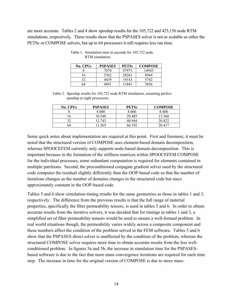
are more accurate. Tables 2 and 4 show speedup results for the 105,722 and 425,156 node RTM simulations, respectively. These results show that the PSPASES solver is not as scalable as either the PETSc or COMPOSE solvers, but up to 64 processors it still requires less run time.
Table 1. Simulation time in seconds for 105,722 node RTM simulation.
Some quick notes about implementation are required at this point. First and foremost, it must be noted that the structured version of COMPOSE uses element-based domain decomposition, whereas SPOOCEFEM currently only supports node-based domain decomposition. This is important because in the formation of the stiffness matrices within SPOOCEFEM COMPOSE for the individual processes, some redundant computation is required for elements contained in multiple partitions. Second, the preconditioned conjugate gradient solver used by the structured code computes the residual slightly differently than the OOP-based code so that the number of iterations changes as the number of domains changes in the structured code but stays approximately constant in the OOP-based code.
Tables 5 and 6 show simulation-timing results for the same geometries as those in tables 1 and 3, respectively. The difference from the previous results is that the full range of material properties, specifically the fiber permeability tensors, is used in tables 5 and 6. In order to obtain accurate results from the iterative solvers, it was decided that for timings in tables 1 and 3, a simplified set of fiber permeability tensors would be used to ensure a well-formed problem. In real world situations though, the permeability varies widely across a composite component and these numbers affect the condition of the problem solved in the FEM software. Tables 5 and 6 show that the PSPASES direct solver is unaffected by the condition of the problem, whereas the structured COMPOSE solver requires more time to obtain accurate results from the less well-conditioned problem. In figures 5a and 5b, the increase in simulation time for the PSPASES-based software is due to the fact that more mass convergence iterations are required for each time step. The increase in time for the original version of COMPOSE is due to more mass-
15
Table 3. Simulation time in seconds for 425,156 node RTM simulation.
Table 5. Simulation time in seconds for 105,722 node RTM simulation with full range of material properties.
No. CPUs PSPASES COMPOSE 8 7165 36299
16 5433 20873 32 4520 13967 64 4891 11652
Table 6. Simulation time in seconds for 425,156 node RTM simulation with full range of material properties.
No. CPUs PSPASES COMPOSE 8 31574 327502
16 27137 157100 32 24034 72669 64 13878 45303
convergence iterations and more iterations in the linear equation solver, thus making the percentage of time increase greater than that for the PSPASES-based software. This is an important point to highlight because choosing a direct or iterative solver in SPOOCEFEM is as easy as changing one variable in the call to the solve routine in the Vector class, whereas adding a new solver to the structured COMPOSE software would require rewriting many routines and changes to a large portion of the application code.
16
Number of CPUs
Sim
ula
tion
Tim
e(s
eco
nd
s)
8 16 24 32 40 48 56 64
5000
10000
15000
20000
25000
30000
35000
40000
PSPASES, 1 MaterialCOMPOSE, 1 MaterialPSPASES, All MaterialsCOMPOSE, All Materials
(a) Plot of solution times for PSPASES and COMPOSE
solvers with 105,722 nodes for single and multiple material models.
Number of CPUs
Sim
ula
tion
Tim
e(s
eco
nd
s)
8 16 24 32 40 48 56 64
50000
100000
150000
200000
250000
300000
350000
PSPASES, 1 MaterialCOMPOSE, 1 MaterialPSPASES, All MaterialsCOMPOSE, All Materials
(b) Plot of solution times for PSPASES and COMPOSE
solvers with 105,722 nodes for single and multiple material models.
Figure 5. Results of PSPASES vs. COMPOSE comparison.
17
6. Conclusions
The SPOOCEFEM framework discussed in this report has demonstrated its usefulness in the development of parallel FEM software. The ease of development, software reuse, and the GUI tools are all advantages of using SPOOCEFEM. As with other OOP designs, the SPOOCEFEM framework required a higher investment in time and thought vs. functional programming approaches. After SPOOCEFEM was developed though, implementation of the application COMPOSE was swift and required little additional code. Much of the functionality available in C++ is used to make developing FEM applications simpler, but making the base FEM development complex. An example of the extensive OOP work is the use of multiple inheritance by COMPOSE in the development of the element classes. Another example is the use of polymorphism in the element and BC classes, making extensions by individual applications efficient. The greatest complexity comes from the Vector and Matrix classes, where various combinations of data and parallel algorithms are located, but accessed through a consistent interface. This complexity is warranted though, as now the application developer is relieved of the task of changing solver calls and data storage to accommodate various new packages or solvers.
7. Future Development
The original impetus to develop SPOOCEFEM was the current work of extending COMPOSE to model the nonisothermal resin flow and cure kinetics in RTM with parallel computers. Because much work would have gone into parallelizing the current serial code with little usable source code for future projects, it was decided to create a reusable framework for FEM software development. Now that the isothermal version of COMPOSE is implemented in the SPOOCEFEM framework, the job of creating the parallel nonisothermal COMPOSE software is much easier and will be available for other projects yet to come. Other sparse matrix formats besides CSR will be added to SPOOCEFEM in the future along with the associated equation solvers. Element-based domain decomposition requires refinement in SPOOCEFEM so that applications can take advantage of it.
18
8. References
Ashcroft, C. C.; Grimes, R. G.; Pierce, D. J.; Wah, D. K. Solving Linear Systems Using SPOOLES 2.2. Boeing Phantom Works, 2002.
Balay, S.; Gropp, W.; McInnes, L. C.; Smith, B. PETSc Users Manual. Argonne National Laboratory: Argonne, IL, 2001.
Clarke, J. A.; Naumburu, R. R. A Distributed Commuting Environment for Interdisciplinary Applications. Concurrency and Computation: Practice and Experience 2002, 14, 1–14.
Ellis, T. M.; Philips, I. R.; Lahey, T. M. FORTRAN 90 Programming; Addison-Wesley, Reading: MA, 1994.
Ford, B. R.; Foschi, R. O.; Stiemer, S. F. Object-Oriented Finite Element Analysis. Computers and Structures 1990, 34, 355–374.
Henz, B. J.; Tamma, K.; Kanapady, R.; Ngo, N. D.; Chung, P. W. Process Modeling of Composites by Resin Transfer Molding: Sensitivity Analysis for Isothermal Considerations; 40th Aerospace Sciences Meeting, Reno, NV, 2002; AIAA-2002-0790.
Joshi, M.; Karypis, G.; Kumar, V. PSPASES: Scalable Parallel Direct Solver Library for Sparse Symmetric Positive Definite Linear Systems; Department of Computer Science: University of Minnesota, 1999.
Karypis, G.; Kumar, V. A Software Package for Partitioning Unstructured Graphs, Partitioning Meshes, and Computing Fill-Reducing Orderings of Sparse Matrices; University of Minnesota/U.S. Army HPC Research Center, Minneapolis, MN, 1997.
Law, K. H. A Parallel Finite Element Solution Method. Computers and Structures 1985, 23, 845–858.
Mackie, R. I. Object-Oriented Programming of the Finite Element Method. International Journal on Numerical Methods in Engineering 1992, 35, 425–436.
Modak, S.; Sotelino, E. D. An Object-Oriented Programming Framework for the Parallel Dynamic Analysis of Structures. Computers and Structures 2002, 80, 77–84.
Mohan, R. V.; Ngo, N. D.; Tamma, K. K. On a Pure Finite Element Methodology for Resin Transfer Mold Filling Simulations. Polymer Engineering and Science 1999, 39, 26–43.
Mohan, R. V.; Shires, D. R.; Mark, A.; Tamma, K. K. Advanced Manufacturing of Large Scale Composite Structures: Process Modeling Manufacturing Simulations and Massively Parallel Computing Platforms. Journal of Advances in Engineering Software 1998, 29, 249–264.
19
Ngo, N. D.; Mohan, R. V.; Chung, P. W.; Tamma, K. K. Recent Developments Encompassing Non-Isothermal/Isothermal Liquid Composite Molding Process Modeling/Analysis: Physically Accurate, Computationally Effective and Affordable Simulations and Validations. Journal of Thermoplastic Composite Materials 1998, 11, 493–532.
Niekamp, R.; Stein, E. An Object-Oriented Approach for Two- and Three-Dimensional Adaptive Finite Element Computations. Computers and Structures 2002, 80, 317–328.
Norris, B.; Balay, S.; Benson, S.; Freitag, L.; Hovland, P.; McInnes, L.; Smith, B. Parallel Components for PDEs and Optimization: Some Issues and Experiences. Parallel Computing 2002, 28, 1811–1831.
Shires, D.; Henz, B. J.; Mohan, R. Architecture-Based Communications Improvements for Domain Decompositions; International Conference on Parallel and Distributed Processing Techniques and Applications, Las Vegas, NV, June 2002.
Shires, D.; Mohan, R.; Mark, A. An Evaluation of HPF and MPI Approaches and Performance in Unstructured Finite Element Simulations; International Conference on Parallel and Distributed Processing Techniques and Applications, 2001a.
Shires, D.; Mohan, R.; Mark, A. Optimization and Performance of a FORTRAN 90 MPI-Based Unstructured Code on Large Scale Parallel Systems; International Conference on Parallel and Distributed Processing Techniques and Applications, Las Vegas, NV, June 2001b.
Sommerville, I. Software Engineering. Addison-Wesley Publishing Company: New York, NY, 1989.
Sun, S.; Marrero, T. R. An Object-Oriented Programming Approach for Heat and Mass Transfer Related Finite Element Analyses. Computers in Chemical Engineering 1998, 22, 1381–1385.
Voller, V. R.; Chen, Y. F. Prediction of Filling Times of Porous Cavities. International Journal for Numerical Methods in Fluids 1996, 23, 661–672.
NO. OF NO. OF COPIES ORGANIZATION COPIES ORGANIZATION
20
1 DEFENSE TECHNICAL (PDF INFORMATION CENTER Only) DTIC OCA 8725 JOHN J KINGMAN RD STE 0944 FT BELVOIR VA 22060-6218 1 COMMANDING GENERAL US ARMY MATERIEL CMD AMCRDA TF 5001 EISENHOWER AVE ALEXANDRIA VA 22333-0001 1 INST FOR ADVNCD TCHNLGY THE UNIV OF TEXAS AT AUSTIN 3925 W BRAKER LN STE 400 AUSTIN TX 78759-5316 1 US MILITARY ACADEMY MATH SCI CTR EXCELLENCE MADN MATH THAYER HALL WEST POINT NY 10996-1786 1 DIRECTOR US ARMY RESEARCH LAB AMSRD ARL D DR D SMITH 2800 POWDER MILL RD ADELPHI MD 20783-1197 1 DIRECTOR US ARMY RESEARCH LAB AMSRD ARL CS IS R 2800 POWDER MILL RD ADELPHI MD 20783-1197 3 DIRECTOR US ARMY RESEARCH LAB AMSRD ARL CI OK TL 2800 POWDER MILL RD ADELPHI MD 20783-1197 3 DIRECTOR US ARMY RESEARCH LAB AMSRD ARL CS IS T 2800 POWDER MILL RD ADELPHI MD 20783-1197
ABERDEEN PROVING GROUND 2 DIR USARL AMSRD ARL CI LP (BLDG 305) AMSRD ARL CI OK TP (BLDG 4600)