Spot Test Kits For Detecting Lead in Household Paint: A Laboratory Evaluation Walter J. Rossiter, Jr. Mark G. Vangel Mary E. McKnight Gary Dewalt Prepared for: U.S. Department of Housing and Urban Development Office of Lead Hazard Control NISTIR 6398
Transcript
Spot Test Kits For DetectingLead in Household Paint:A Laboratory Evaluation
Walter J. Rossiter, Jr.Mark G. Vangel
Mary E. McKnightGary Dewalt
Prepared for: U.S. Department of Housing and Urban Development
Office of Lead Hazard Control
NISTIR 6398
NISTIR 6398
Spot Test Kits For DetectingLead in Household Paint:A Laboratory Evaluation
Walter J. Rossiter, Jr.*
Mark G. Vangel**
Mary E. McKnight*
*Building and Fire Research Laboratory**Information Technology Laboratory
National Institute of Standards and TechnologyGaithersburg, MD 20899-8621
Gary Dewalt
QuanTechRosslyn, VA 22209-1607
May 2000
U.S. Department of Commerce William M. Daley, Secretary
Technology Administration
Dr. Cheryl L. Shavers, Under Secretary of Commerce for Technology
National Institute of Standards and Technology
Raymond G. Kammer, Director
Prepared for:
U.S. Department of Housing and Urban Development Andrew M. Cuomo, Secretary
Office of Lead Hazard Control
David E. Jacobs, Director
iii
ABSTRACT A laboratory study was conducted to determine the reliability of spot test kits for detecting the presence of lead in household paint when tests were conducted by certified lead inspectors or risk assessors. Reagent solutions were applied to paint specimens and, subsequently, the specimens were observed for characteristic color change. For the study, four test kits were based on the reaction of lead ion with sulfide ion to produce a gray or black color, whereas four others were based on the reaction of lead ion with rhodizonate ion to give a pink or red color. These eight kits were used in an experiment investigating the effect of lead level, lead pigment type, operator, paint-film substrate, overlayer paint type, and overlayer paint thickness. Test samples, prepared using either a white lead (i.e., basic lead carbonate) or a lead chromate pigment, had ten lead levels ranging from 0 mg/cm2 to 3.5 mg/cm2. Five operators were trained according to test protocols based on each kit manufacturer’s instructions. The study showed that the spot test kits gave positive results at lead levels less than 1 mg/cm2. Consequently, a positive response could not be relied on to indicate the presence of lead-based paint, which is defined as paint having lead levels equal to, or greater than, 1 mg/cm2. This finding is consistent with the results of past field studies. A criterion against which a spot test kit may be considered as acceptable for use as a negative screen (i.e., a test for which a negative result indicates a low probability of lead $ 1 mg/cm2) for the presence of lead-based paint was proposed. This criterion is: Upon evaluation of spot test kit response, the probability of a negative response (with 95 % confidence) at a lead level of 1 mg/cm2 is # 5%. Equivalently, the lead level at which there is a 95 % probability of a positive response (with 95 % confidence) should be # 1 mg/cm2. The type of lead pigment had a significant effect on the spot test kit response. For white lead specimens, six kits—three sulfide-based and three rhodizonate-based—gave low percents of false negatives (# 2 %) and met the proposed criterion for acceptance as a negative screen for lead-based paint. For lead chromate specimens, three of these six kits—two sulfide-based and one rhodizonate-based—also had low percents of false negatives (# 2 %) and met the proposed acceptance criterion. The other factors—overlayer type, overlayer thickness, operator, and substrate—did not generally show significant effects in cases where the spot test kits appeared to be candidates for use as negative screens for lead-based paint. Finally, the study results lead to the suggestion that an evaluation of spot test kit response should afford a low percent of positive results at the 0 mg/cm2 lead level because, in practice, false-positives may needlessly spur test kit users into taking further, but unnecessary, investigative action for the presence of lead. Key words: building technology; detection; kit response; lead-based paint; lead level; lead chromate; operator effect; spot test kits; testing; white lead
iv
TABLE OF CONTENTS
Page ABSTRACT................................................................................................................................... iii 1. INTRODUCTION......................................................................................................................1
1.1 Background....................................................................................................................1 1.2 Objective and Scope of the Study ...................................................................................3
3. SPOT TEST KITS IN THE STUDY ........................................................................................ 11
3.1 Kits Having Multiple Test Procedures........................................................................... 12 4. EXPERIMENTAL ................................................................................................................... 13
4.1 Sample Preparation....................................................................................................... 13 4.1.1 Leaded Paint .................................................................................................. 13 4.1.2 Leaded-Paint Films ........................................................................................ 14 4.1.3 Coated Test Panels......................................................................................... 15 4.1.4 Surface Test Grid and Panel Identification...................................................... 16 4.1.5 Leaded-Paint Chips ........................................................................................ 16 4.1.6 Selection of Lead Levels ................................................................................ 16 4.1.7 Laboratory Lead Analysis............................................................................... 16
4.2 Testing and Data Recording ......................................................................................... 17 5. RESULTS AND DISCUSSION ............................................................................................... 24
5.1 False Negatives and False Positives............................................................................... 24 5.1.1 Effect of STK4 Test Procedure ...................................................................... 27
5.2 Factors Affecting Spot Test Kit Response..................................................................... 28 5.2.1 Method of Analysis ........................................................................................ 28 5.2.2 Effect of Overlayer Type and Overlayer Thickness ......................................... 28 5.2.3 Effect of Lead Pigment Type.......................................................................... 29 5.2.4 Effect of Operator.......................................................................................... 30
5.3 Modeling the Probability of Spot Test Kit Response ..................................................... 31 5.3.1 Ideal Test Kit Performance for Detecting Lead-Based Paint ........................... 45 5.3.2 Effect of Spot Test Kit................................................................................... 46 5.3.3 Effect of Lead Pigment Type.......................................................................... 46 5.3.4 Effect of Spot Test Kit Procedure .................................................................. 46 5.3.5 Effect of Operator.......................................................................................... 47 5.3.6 Effect of Substrate ......................................................................................... 47 5.3.7 Comparison of NIST Laboratory Data with EPA/HUD Field Data ................. 48
5.4 Upper Confidence Limits on the Lead Level Having a 95 % Probability of a Positive Response......................................................................................................... 55
6. SUMMARY AND CONCLUSIONS ........................................................................................ 57
v
7. ACKNOWLEDGMENTS......................................................................................................... 59 8. REFERENCES......................................................................................................................... 59 APPENDIX A. ADDITIONAL TABULATIONS OF FALSE NEGATIVES AND FALSE POSITIVES ....................................................................................................... A1 APPENDIX B. TABULATIONS OF THE RESULTS OF MODELING TEST KIT
RESPONSE VERSUS LEAD LEVEL ............................................................... B1 LIST OF TABLES
Page Table 1. Factors varied during the study..........................................................................................4 Table 2. Spot test kits and methods of use.......................................................................................6 Table 3. Numbers of test kits, lead levels, operators, and lead pigment types selected in the experimental design for kits used to test paint films adhered to substrates ....................8 Table 4. Combinations of substrate, overlayer type, and overlayer thickness selected in
the experimental design for kits used to test paint films adhered to substrates ...................8 Table 5A. Experimental design combinations for white lead including four controls.........................9 Table 5B. Experimental design combinations for lead chromate.................................................... 10 Table 6. Results of sodium sulfide analyses of sulfide-based spot test kits ...................................... 12 Table 7. Lead levels prepared in the study ..................................................................................... 13 Table 8A. Targeted and mean lead levels for the test panels having white lead
and non-reactive substrates........................................................................................... 18 Table 8B. Targeted and mean lead levels for the test panels having white lead
and reactive substrates.................................................................................................. 19 Table 8C. Targeted and mean lead levels for the test panels having lead
chromate and non-reactive substrates ........................................................................... 20 Table 8D. Targeted and mean lead levels for the test panels having lead
chromate and reactive substrates .................................................................................. 21 Table 9A. Targeted and mean lead levels for chips with white lead ................................................ 22 Table 9B. Targeted and mean lead levels for chips with lead chromate .......................................... 23
vi
Table 10A. False negatives and false positives at a lead level of 0 mg/cm2 ..................................... 25 Table 10B. False negatives and false positives at a lead level of 1.0 mg/cm2................................... 27 Table 11. F-tests of the significance of overlayer type and overlayer thickness............................... 29 Table 12. F-tests of the significance of lead pigment type .............................................................. 30 Table 13. F-tests of the significance of operator ............................................................................ 31 Table 14. Lead level corresponding to a 95 % probability of a positive response for
an Aaverage@ operator .................................................................................................... 56 Table A1. False negatives and false positives at a lead level of 0.5 mg/cm2 ................................... A1 Table A2. False negatives and false positives at a lead level of 0.7 mg/cm2 ................................... A2 LIST OF FIGURES Page Figure 1. Probability of a Positive Response Versus Lead Level for Spot Test Kit 1 (STK1)
for Each Operator. (The filled circles represent the proportions of positive responses at a given lead level, and the error bars are the associated 95 % binomial confidence intervals. The two horizontal dashed lines represent the 0.5 and 0.95 probabilities of a positive response. Circles are the 0.95 probability point for each operator; they are repeated above the horizontal axis for clarity.) ………………………33
Figure 2. Probability of a Positive Response Versus Lead Level for Spot Test Kit 2 (STK2)
for Each Operator. (The filled circles represent the proportions of positive responses at a given lead level, and the error bars are the associated 95 % binomial confidence intervals. The two horizontal dashed lines represent the 0.5 and 0.95 probabilities of a positive response. Circles are the 0.95 probability point for each operator; they are repeated above the horizontal axis for clarity.) ………………………34
Figure 3. Probability of a Positive Response Versus Lead Level for Spot Test Kit 3 (STK3)
for Each Operator. (The filled circles represent the proportions of positive responses at a given lead level, and the error bars are the associated 95 % binomial confidence intervals. The two horizontal dashed lines represent the 0.5 and 0.95 probabilities of a positive response. Circles are the 0.95 probability point for each operator; they are repeated above the horizontal axis for clarity.) ………………………35
Figure 4A. Probability of a Positive Response Versus Lead Level for Spot Test Kit 4 for Each
Operator; Data Are For the STK4a Procedure. (The filled circles represent the proportions of positive responses at a given lead level, and the error bars are the associated 95 % binomial confidence intervals. The two horizontal dashed lines represent the 0.5 and 0.95 probabilities of a positive response. Circles are the 0.95 probability point for each operator; they are repeated above the horizontal axis for clarity.)........................................................................................................................ 36
vii
viii
Figure 4B. Probability of a Positive Response Versus Lead Level for Spot Test Kit 4 for Each Operator; Data Are For the STK4b Procedure. (The filled circles represent the proportions of positive responses at a given lead level, and the error bars are the associated 95 % binomial confidence intervals. The two horizontal dashed lines represent the 0.5 and 0.95 probabilities of a positive response. Circles are the 0.95 probability point for each operator; they are repeated above the horizontal axis for clarity.)........................................................................................................................ 37
Figure 4C. Probability of a Positive Response Versus Lead Level for Spot Test Kit 4 for Each
Operator; Data Are For the STK4c Procedure. (The filled circles represent the proportions of positive responses at a given lead level, and the error bars are the associated 95 % binomial confidence intervals. The two horizontal dashed lines represent the 0.5 and 0.95 probabilities of a positive response. Circles are the 0.95 probability point for each operator; they are repeated above the horizontal axis for clarity.)........................................................................................................................ 38
Figure 5. Probability of a Positive Response Versus Lead Level for Spot Test Kit 5 (STK5)
for Each Operator. (The filled circles represent the proportions of positive responses at a given lead level, and the error bars are the associated 95 % binomial confidence intervals. The two horizontal dashed lines represent the 0.5 and 0.95 probabilities of a positive response. Circles are the 0.95 probability point for each operator; they are repeated above the horizontal axis for clarity.)……………………….39
Figure 6. Probability of a Positive Response Versus Lead Level for Spot Test Kit 6 (STK6)
for Each Operator. (The filled circles represent the proportions of positive responses at a given lead level, and the error bars are the associated 95 % binomial confidence intervals. The two horizontal dashed lines represent the 0.5 and 0.95 probabilities of a positive response. Circles are the 0.95 probability point for each operator; they are repeated above the horizontal axis for clarity.)……………………….40
Figure 7A. Probability of a Positive Response Versus Lead Level for Spot Test Kit 7 for Each
Operator; Data Are For the STK7a Procedure. (The filled circles represent the proportions of positive responses at a given lead level, and the error bars are the associated 95 % binomial confidence intervals. The two horizontal dashed lines represent the 0.5 and 0.95 probabilities of a positive response. Circles are the 0.95 probability point for each operator; they are repeated above the horizontal axis for clarity.)........................................................................................................................ 41
Figure 7B. Probability of a Positive Response Versus Lead Level for Spot Test Kit 7 for Each
Operator; Data Are For the STK7b Procedure. (The filled circles represent the proportions of positive responses at a given lead level, and the error bars are the associated 95 % binomial confidence intervals. The two horizontal dashed lines represent the 0.5 and 0.95 probabilities of a positive response. Circles are the 0.95 probability point for each operator; they are repeated above the horizontal axis for clarity.)........................................................................................................................ 42
ix
Figure 8A. Probability of a Positive Response Versus Lead Level for Spot Test Kit 8 for Each Operator; Data Are For the STK8a Procedure. (The filled circles represent the proportions of positive responses at a given lead level, and the error bars are the associated 95 % binomial confidence intervals. The two horizontal dashed lines represent the 0.5 and 0.95 probabilities of a positive response. Circles are the 0.95 probability point for each operator; they are repeated above the horizontal axis for clarity.) ....................................................................................................................... 43
Figure 8B. Probability of a Positive Response Versus Lead Level for Spot Test Kit 8 for Each
Operator; Data Are For the STK8b Procedure. (The filled circles represent the proportions of positive responses at a given lead level, and the error bars are the associated 95 % binomial confidence intervals. The two horizontal dashed lines represent the 0.5 and 0.95 probabilities of a positive response. Circles are the 0.95 probability point for each operator; they are repeated above the horizontal axis for clarity.) ....................................................................................................................... 44
Figure 9. Example of the Ideal Performance of a Spot Test Kit for Determining Lead-Based
Paint. ............................................................................................................................. 45 Figure 10. Comparison of the Results of the NIST Laboratory Data With Those of the
EPA/HUD Field Data [8] for Spot Test Kit 3. (The solid and dashed curves represent the NIST and EPA/HUD data, respectively.) ................................................ 50
Figure 11. Comparison of the Results of the NIST Laboratory Data With Those of the
EPA/HUD Field Data [8] for Spot Test Kit 4. The Comparison was Made for the STK4b Procedure. (The solid and dashed curves represent the NIST and EPA/HUD data, respectively.) ..................................................................................... 51
Figure 12. Comparison of the Results of the NIST Laboratory Data With Those of the
EPA/HUD Field Data [8] for Spot Test Kit 6. The EPA/HUD Study did not Include Data for a Reactive Substrate. (The solid and dashed curves represent the NIST and EPA/HUD data, respectively.)................................................................ 52
Figure 13. Comparison of the Results of the NIST Laboratory Data With Those of the
EPA/HUD Field Data [8] for Spot Test Kit 7. The Comparison was Made for the STK7b Procedure. (The solid and dashed curves represent the NIST and
EPA/HUD data, respectively.) ..................................................................................... 53 Figure 14. Comparison of the Results of the NIST Laboratory Data With Those of the
EPA/HUD Field Data [8] for Spot Test Kit 8. The Comparison was Made for the STK8b Procedure. (The solid and dashed curves represent the NIST and
1. INTRODUCTION 1.1 Background According to a recent report by the President’s Task Force on Environmental Health Risks and Safety Risks to Children, approximately 24 million U.S. dwellings were at risk for lead-based paint hazards in 1999 [1]. As defined in Public Law 102-550, Residential Lead-Based Paint Hazard Reduction Act of 1992, the term lead-based paint means paint or other surface coatings that contain lead at contents that Aequal or exceed a level of 1.0 milligram per centimeter squared or 0.5 percent by weight@ [2]. A definition is also given in the Guidelines for the Evaluation and Control of Lead-Based Paint Hazards in Housing, a document often called the HUD Guidelines [3]. The accurate and efficient identification of lead-based paint in housing is important to the Federal government. For example, identification of lead-based paint in most pre-1978 Atarget@ housing∗ requires disclosure of that information, if available, to the owner, prospective purchasers, or tenants (42 U.S.C. 4852d, 24 CFR 35.80-98). Also, in certain target housing receiving financial assistance from HUD, or being sold by the Federal government, identification of lead-based paint results in requirements for lead-based paint hazard evaluation and/or control (42 U.S.C. 4822, 24 CFR 35.1-1355). As far back as the early 1970s, spot tests were introduced as relatively nonintrusive, potentially cost-saving, qualitative methods for determining the presence or absence of lead-based paint on-site [4,5]. A spot test involves Athe application of reagent solution to a prepared dry paint film sample, paint chip, paint powder, or painted surface and the subsequent observation for the presence or absence of the characteristic color change@ [6]. Presently, two types of spot tests are used for detecting lead in paint, and prepackaged kits are commercially available from a number of suppliers [7,8]. One type is based on the reaction of rhodizonate ion with lead II ion; this reaction produces in acidic solution a color change from yellow-orange to pink or red. The other is based on the reaction of sulfide ion with lead II ion; here the color change is from clear to gray or black.∗∗ In performing a spot test, the basic procedure is to cut a notch through, or to abrade the surface of, the paint film, then to place the reagent solution on that location, and finally to observe qualitatively whether a characteristic color change occurs. Variations to this general procedure include placing the reagent solution on paint chips, and mixing paint chips in a leaching solution which is, in turn, tested with the reagent. The American Society for Testing and Materials (ASTM) has issued two standards associated with the use of spot tests: ASTM E 1753, Practice for Use of Qualitative Chemical Spot Test Kits for Detection of Lead in Dry Paint Films [6] and ASTM E 1828, Guide for Evaluating the Performance Characteristics of Qualitative Chemical Spot Test Kits for Lead in Paint [9]. Potential advantages to using spot tests over other methods of identifying lead-based paint include that spot test methods: are inexpensive and rapid, may require minimal operator technique, and may respond to microgram levels of analyte [7]. The major barrier to the acceptance of spot tests has been indications that they may be unreliable for identifying lead-based paint [8,10,11]. For example,
*The definition of target housing in the HUD Guidelines [3] is: Any residential unit constructed before 1978,
except dwellings that do not contain bedrooms or dwellings that were developed specifically for the elderly or persons with disabilitiesCunless a child younger than 6 resides or is expected to reside in the dwelling. In the case of jurisdictions that banned the sale or use of lead-based paint before 1978, the Secretary of HUD may designate an earlier date for defining target housing.
**The two types of spot tests are referred to as rhodizonate and sulfide in this report.
2
a 1997 EPA report [11] indicated the following concerns: spot tests are subject to positive results in which lead is indicated when it is not present at significant levels; spot test reagents may not solubilize the lead resulting in false negative∗ results indicating the absence of lead when it is present in significant levels; and spot tests do not provide a reliable transition from negative response to positive response at the Federal level at which a paint is classified as lead-based (i.e., 1 mg/cm2). Many studies [7,8,11-20] have been conducted in the laboratory and field to evaluate the performance of spot tests. In one of the earliest studies in the late 1970s, Vind, Mathews, Alumbaugh, and Hamilton [12] reported that they were able to forego laboratory analysis of 150 out of 250 field paint samples because the spot tests conducted with sodium sulfide reagent were considered Aunquestionably negative.@ In the late 80s, in a study incorporating about 70 samples, McKnight, Byrd, Roberts, and Lagergren [13] suggested that spot tests conducted by experienced technicians may be useful in indicating the presence of lead at or near the lead-based paint level of 1 mg/cm2, but recommended further evaluation. More recently, Ashley, Hunter, Tait, Dozier, Seaman, and Berry [20] concluded from a study of about 200 paint films using a rhodizonate spot test kit that Ain-situ testing of lead in paint by [....] chemical spot test kits can be used for screening (i.e., qualitative) purposes.@ In contrast to these examples, a 1995 field study jointly funded by EPA and HUD [8] concluded that test kits should not be used for lead paint testing because they Acannot determine the extent of lead-based paint in a home...@ This EPA/HUD study included the most extensive field testing conducted with spot test kits. It incorporated six kits (4 rhodizonate and 2 sulfide), five of which were each used on about 1300 test locations. The testing was conducted by individuals selected to represent typical homeowners who might purchase kits for personal use. The conclusion not to use test kits for identifying lead-based paint was based, in part, on the finding that they varied widely in performance and that none demonstrated low percents of both false positive and false negative results in comparison with the Federal level of 1 mg/cm2 at which a paint is classified as lead-based. Similarly, in a narrower 1997 field study involving two test kits (1 rhodizonate and 1 sulfide) and 120 test locations, Reames, Brumis, Lance, and Schwartzberg [19] recommended that spot test kits not be used for lead-based paint inspection. In this case, the authors found that, although low percents of false negatives were achieved at the 1 mg/cm2 level, both test kits had high percents of false positives. Spot tests are not currently used in Federal programs for assessing the presence or absence of lead-based paint in housing. The present study is intended to provide further evaluation of spot test kit performance and, in particular, when they are used by well-trained operators in a well-controlled, systematic laboratory study. The results would help to support future decisions regarding their possible use. If the results indicate that spot tests are reliable under well-controlled, laboratory conditions, follow-up studies might be justified to pinpoint reasons why some field studies have found spot tests to be unreliable. Conversely, if the results of a well-controlled laboratory experiment found spot tests to be unreliable, then further field studies would not be appropriate. Thus, HUD requested that the National Institute of Standards and Technology (NIST) conduct a well-controlled, systematic laboratory study on the reliability of spot tests for detecting lead in household paint.
*A false negative has been defined as a test result that is negative for lead, but the true value is above the
selected lead level [8]. Conversely, a false positive is a test result that is positive for lead, but the true value is below the selected lead level.
3
1.2 Objective and Scope of the Study This report presents the results of the HUD-sponsored study to determine the reliability of spot test kits for detecting the presence of lead in household paints when tests are conducted in the laboratory by certified lead inspectors or risk assessors. Seven factors that may affect the performance of spot tests were varied according to a predetermined experimental design. Descriptions of these seven factorsCspot test kit, lead level*, lead pigment type, operator, paint film substrate, overlayer type, and overlayer thicknessCare given in Table 1 with a comment as to why each factor was included. Table 2 provides information on the eight spot test kits, designated STK1 through STK8. The test samples were prepared in the laboratory, which allowed control of the design factors, and made possible a balanced statistical design. During the testing, the response of each test kit (i.e., negative or positive) for each specimen was recorded. The data were statistically analyzed (1) to determine the effects of the factors incorporated in the design (Table 1) or interactions among them, and (2) to quantify the probability of lead detection through use of each spot test kit. HUD not only sponsored this study at NIST, but also a complementary study conducted by QuanTech, Rosslyn, VA. The objectives of the QuanTech study were to generate a guide for using spot test kits for detecting the presence of lead-based paint in residential housing, and to validate the use of laboratory-prepared test samples as surrogates for field samples. Because the two studies were complementary, NIST and QuanTech performed much of the research cooperatively. Only one set of laboratory test samples was prepared for both the NIST and QuanTech studies, and most of the spot test kits used were common to both. QuanTech research staff conducted its laboratory spot tests in the NIST laboratories, and the results are included in the present report as Op4 and Op5 data. Note that the complementary QuanTech study produced two reports, The Use of Manufactured Samples for Evaluating Spot Test Kits for Detecting Lead in Household Paints [21], and Guidance for the Evaluation of Spot Test Kits for Detecting the Presence of Lead in Household Paints [22]. 2. EXPERIMENTAL DESIGN 2.1 Factors Affecting Spot Test Kit Response Factors other than lead level are variable in practice and may affect spot test response. For example, for both rhodizonate- and sulfide-based spot tests, more than one kit is available, and human involvement in subjectively judging response may affect the results. Different types of lead pigments have historically been used in paint production and differences in their solubilities can also affect response. Also, depending on the age of a residence and how often it has been painted, the type and thickness of paint layers covering lead-containing paint films may affect the results. The factors included in the experimental design are described in Table 1. A key consideration is the lead level at which the spot test kit response changes from negative to positive; consequently, 10 lead levels were incorporated in the design. Equally important is recognition that different kits used by various operators may have varying response for a given test sample and, thus, eight test kits and five operators were included. Two levels each were chosen for lead pigment type, film substrate, overlayer type, and overlayer thickness. In these cases, the levels
*HUD prefers determining the amount of lead in a paint film on the basis of area content (i.e., mg/cm2) as
opposed to mass concentration. Hence, the experimental design of this study is based on area content, which is referred to as Alead level@ in this report.
4
were selected to be representative of real-world practiceCfor example, latex and oil-based paint overlayersCor to bracket the extremes of what is likely to be encountered in practiceCfor example, the solubility of the lead pigment, and thin and thick overlayers (Table 1). Table 1. Factors varied during the study
Factor Description Comment
Spot Test Kit
Eight spot test kits were included: $ Spot Test Kit 1 (STK1) $ Spot Test Kit 2 (STK2) $ Spot Test Kit 3 (STK3) $ Spot Test Kit 4 (STK4) $ Spot Test Kit 5 (STK5) $ Spot Test Kit 6 (STK6) $ Spot Test Kit 7 (STK7) $ Spot Test Kit 8 (STK8)
In practice, spot test kits are available from a number of suppliers. Four rhodizonate and four sulfide kits were included in the study. For both types, the selected kits covered the range of kits used in practice for examining the entire paint film (by notching, coring, or chipping), and not just the surface of the paint film. Seven of the eight kits were commercial products. STK8 was a kit available to professional inspectors and risk assessors through a state government laboratory. STK1, STK2, STK7, and STK8 were sulfide kits; STK3 through STK6 were rhodizonate kits. STK2 was sold to test only chips and, consequently, the paint film specimens tested with STK2 were not adhered on a substrate.
Lead Level
Ten lead levels were chosen for each lead pigment type. For both leads, the targeted range was from no lead added to 3.5 mg/cm2. The targeted values (in mg/cm2 ) were as follows: white lead lead chromate $ 0 $ 0 $ 0.1 $ 0.5 $ 0.2 $ 0.7 $ 0.3 $ 1.0 $ 0.4 $ 1.2 $ 0.5 $ 1.6 $ 0.7 $ 1.8 $ 1.0 $ 2.0 $ 1.6 $ 2.5 $ 3.5 $ 3.5
In practice, lead in paint films in existing houses varies from essentially none (i.e., lead was not purposely added to the paint) to substantial. For example, mean lead levels in the range of 2 mg/cm2 to 3 mg/cm2 have been measured in field studies [8,19]. The ranges of lead level in the present study were consistent with those found in the field. The ten values for each lead pigment type were chosen on the basis of a preliminary experiment (Section 4.1.6), and more high levels were taken for the less soluble lead chromate pigment. Note 1: A lead level of 0 mg/cm2 is the designation assigned to test panels for which lead was not added to the paint films. Measurements showed that the lead levels of these panels was < 0.009 mg/cm2 (Section 4.1.7). Note 2: A distinction between white lead and lead chromate for specimens having a 0 mg/cm2 lead level is artificial because such specimens do not contain lead. Nevertheless, the distinction is maintained in the discussions because of the balance of the experimental design.
In practice, spot test kits are available to many people whose abilities may vary considerably. The operator factor addressed the effect of Athe human element@ on test kit response. Initial planning for the experimental program considered selecting three operators (Op1 through Op3), who were required to be either certified lead inspectors or risk assessors. During experimental design, two additional operators (Op4 and Op5) became available for participation. They did not conduct tests with STK2 and STK8. Because their partial participation provided additional data for STK1, and STK3 through STK7, they were included in the test program. Op4 and Op5 were QuanTech research professionals having experience in the use of spot test kits. Both had passed an EPA lead-inspector training course, although neither was certified. Before beginning the test program, Op1, Op2, and Op3 were examined at the NIST Health Unit for red colorblindness. Op4 and Op5 had been checked during a previous spot test kit study. None of the five operators were red colorblind.
5
Table 1. Factors varied during the study (cont.)
Factor Description Comment Lead Pigment Type
Two lead pigment types were included: $ relatively soluble (white lead) $ relatively insoluble (lead
chromate)
In practice, a number of lead-based pigments have historically been used in paint production. These include basic lead carbonate, basic lead sulfate, lead silicate, chrome yellows and oranges (lead chromate combined with lead sulfate, lead carbonate, and lead phosphate to obtain different hues), chrome greens (chrome yellow and iron blue), molybdate orange (lead molybdate and lead sulfate) and red lead (Pb3O4) [23]. The most common pigment was basic lead carbonate, whose composition is approximately 2PbCO3CPb(OH)2 [24-26]. This pigment is often referred to as Awhite lead,@ which is the term used in this report. White lead is relatively soluble compared to other lead pigments. In the study, white lead and lead chromate were selected to cover the solubility range of lead pigments. Although used considerably less than white lead, lead chromate was a basic pigment for some green, red, orange, and yellow house paints through the mid-1960s [26].
Substrate
Two types of substrates, a non-reactive (NR) and a reactive (R), substrate, were included for spot tests conducted on panel samples: $ sulfide: wood (NR) steel (R) $ rhodizonate: wood (NR) plaster (R)
In practice, lead-based paint has been applied to may different substrates. The reactivity, or nonreactivity, of the substrate may affect spot test response. For example, steel and plaster substrates can affect sulfide and rhodizonate spot tests, respectively [6]. The substrate factor investigated the effect of substrate reactivity on test kit response. It was beyond the scope of the study to include all three substrates for all kits, as steel was considered to be non-reactive for rhodizonate, and plaster was considered non-reactive for sulfide.
Overlayer Type
Two overlayer types were included: $ latex paint $ oil-based paint
In practice, lead-based paint is quite likely to be covered with additional layers of paint. These overlayers may be latex or oil-based paint. This factor was included to determine if the type of overlayer paint affects spot test response.
Overlayer Thickness
Two overlayer thicknesses were included: For panels on substrates: $ thin: about 0.13 mm to 0.28 mm (0.005 in to 0.011 in) $ thick: about 0.75 mm to 1.4 mm (0.030 in to 0.055 in)
In practice, spot test kits have been used to test paint layers having varying thicknesses. For example, Reames et al. [19] reported thickness values ranging from about 0.1 mm to 1.5 mm (0.004 in to 0.060 in). This factor was included to determine if overlayer thickness affects spot test response. The thicknesses of the thin and thick overlayers were selected to cover the range of overlayer thicknesses measured in the field.
6
Table 2. Spot test kits and methods of use Spot Test Kit
Spot Test
Type
Characteristic
Color for Leada
General Method of Usea
STK1 Sulfide Gray to black $ Cut a notch through the paint exposing all layers; illuminate where necessary and examine with a magnifying glass to insure that all layers are exposed.
$ Place a small drop of the reagent solution on one half of the notch; this allows a comparison with the untreated section of the notch.
$ Observe test surface for characteristic color. $ A vial of lead acetate paper is supplied with the kit to check reagent.
STK2 Sulfide Brown or black $ Place about 1 teaspoon of chips in a test tube (provided with kit). $ Add an equal amount of vinegar to the test tube. $ Cap test tube and let stand for 24 h. $ Stir using plastic pipette; then allow solids to settle. $ Add up to 10 drops of reagent to the test tube. $ Observe test tube for characteristic color.
STK3 Rhodizonate Pink to dark purple
$ Remove all dust and dirt. $ Cut or scrap through all paint layers to expose bare surface . $ Moisten pad, which is impregnated with reagent, with about 5 drops of
water using eye dropper; do not over wet. $ Press moistened pad firmly against test surface for about 2 min. $ Observe color of the pad or test surface for characteristic color. $ If no color occurs within 2 min, immediately check reagent using test
verification card (press pad on card for 15 s).
STK4 Rhodizonate Pink or red $ Remove all dust and dirt. $ Cut a notch at a diagonal down to substrate surface. $ Activate test swab by crushing on marked points, then shake and squeeze
with tip facing down until yellow liquid comes to tip; use activated swab immediately.
$ While squeezing swab, rub it on the notched area for 30 s. $ Complete test within 2 min. $ Observe swab and/or paint surface for characteristic color. $ If no characteristic color, use test confirmation card to check reagent. $ If the 2-min result is negative and lead chromate is suspected because of
the paint color (e.g., yellow or green), place used swab in a plastic bag; check swab after 30 min and 60 min or next morning; alternatively, rub a crushed paint chip with a freshly activated swab, and check swab tip and crushed chip for up to 18 h.
[Note: the experimental design for the study included obtaining data for STK4 response when determined after the three time periods: - STK4a was the designation for the data set obtained when the first
swab was examined within 2 min. - STK4b was the designation for the data set obtained when the first
used swab was later re-examined. - STK4c was the designation for the data set obtained when the
second swab in contact with chips was examined. In the case of both STK4b and STK4c for test protocol uniformity, the swab examinations were made after the swabs were kept overnight.]
$ For paint on plaster, because sulfates can interfere, if test appears
negative, rub swab on confirmation card to check reactivity; if no color on test dot, test is not valid.
aThe information in this column was taken from kit manufacturers= instructions.
7
Table 2. Spot test kits and methods of use (cont.) Spot Test Kit
Spot Test
Type
Characteristic
Color for Leada
General Method of Usea
STK5 Rhodizonate Pink to rose/red $ Clean surface with a lead-free paper towel, cloth, or wipe; allow to dry. $ Cut a V-notch in paint film to bare substrate. $ Place 2 drops of leaching solution on the tip of an unused swab. $ Rub swab tip gently on notch at 90E angle for 15 s. $ Rub swab tip on test card (i.e., reagent card) at 90E angle; before using
the card for the first time, perform a QC test to assure reactivity. $ Observe test card and/or swab tip for characteristic color. $ For paint on plaster, separate paint from plaster (no specifics given)
before lead test; if negative, perform a QC test immediately on swab.
STK6 Rhodizonate Pink to rose/red $ Using borer (supplied with kit), cut through paint to substrate; do not collect any paint that prior to removal of borer.
$ Remove borer from surface; collect chips on collection paper. $ Scrape any chips in cut onto collection paper. $ Using a stirring rod, dislodge chips in borer onto collection paper. $ Place paint in vial; grind for about 10 s using stirring rod. $ Add 3 drops of leaching solution into vial. $ Vigorously grind paint in vial for 10 s; then let stand for 20 s. $ Touch swab tip on leaching solution surface. $ Rub swab tip on test card (i.e., reagent card) at 90E angle; before using
the card for the first time, perform a QC test to assure reactivity. $ Observe test card and/or swab tip for characteristic color. $ For paint on plaster, eliminate it from paint specimen (no specifics given)
before placing specimen in vial; if negative, immediately perform a QC test.
STK7 Sulfide Light gray to dark gray to
black
$ Mix water and solid sodium sulfide to prepare reagent solution. $ Reagent may be applied to either painted surfaces or paint chips. $ For surfaces, make a diagonal cut (i.e., notch) through all paint layers. $ For chips, test both surfaces; cleave chips to test sandwiched layers. $ Apply reagent (a few drops) to the chips or painted surfaces, wait up to a
couple of minutes for the characteristic color to form. $ Kit is not for use on painted metallic surfaces; chips are to be used.
[Note: the experimental design included tests on both notches and chips. The test of the notch was first conducted; if it was negative, then a test of a chip was conducted: - STK7a was the designation for the data set for notch tests - STK7b was the designation for the data set for chip tests.]
STK8 Sulfide Gray to black $ Reagent may be applied to either painted surfaces or paint chips. $ For chips, include all layers down to the substrate; cut a cross-section and
apply reagent to both surfaces and the cross-section. $ For painted surfaces, clean them with a non-abrasive solution, then rinse
and dry. $ Notch surface exposing all layers of paint; add a drop of reagent on
notch. $ After applying reagent, check for the characteristic color for up to 30 s. $ Kit is not for use on paint on metal substrates; remove a chip and test it.
[Note: the experimental design included tests on both notches and chips. The test of the notch was first conducted; if it was negative, then a test of a chip was conducted: - STK8a was the designation for the data set for notch tests - STK8b was the designation for the data set for chip tests.]
aThe information in this column was taken from kit manufacturers= instructions.
8
2.2 Fractional Factorial Design A naive approach to experimentation would vary each of the seven factors individually, leaving all but one factor set at >typical' values for each experiment. This form of experimentation is highly inefficient, since it provides no information on potential interactions among the factors. A statistical design that requires testing at all combinations of levels for all factors is called a (full) factorial design. In cases of multi-factor studies, a full factorial design is seldom chosen for initial investigations because such a design would not be an efficient use of resources. Instead, a carefully chosen fraction of all possible combinations is usually selected to examine those effects considered most important. Such a design, called a fractional factorial, was used in this study for those spot test kits (STK1 & STK3-STK8) used on paint-film samples adhered to substrates (i.e., panels). In the case of paint-film samples adhered to substrates, all combinations of test kits, lead levels, operators, and lead pigment types were included in the design with the exception that Operator 4 and Operator 5 did not conduct tests with STK8 (Table 3). These four factors were considered to be the most important of the seven that might affect spot test response. Also included in this experimental design were four of the eight possible combinations of substrate, overlayer type, and overlayer thickness (Table 4). A benefit of this half-fractionation was that the design would reduce to a full factorial if test kit response was found not to be affected by any one of the three factors, substrate, overlayer type, and overlayer thickness. Tables 5A and 5B present a description of the 84 test combinations for the series of white lead and lead chromate samples, respectively, having paint films
Table 3. Numbers of test kits, lead levels, operators, and lead pigment types selected in the experimental design for kits used to test paint films adhered to substrates
Level Selected for the Experimental Design
Factor Op1 - Op3 Op4 & Op5 Test Kit
7
6
Lead Level
10
10
Operator
3
2
Lead Pigment Type
2
2
Table 4. Combinations of substrate, overlayer type, and overlayer thickness selected in the experimental design for kits used to test paint films adhered to substrates
Substratea Overlayer Type Overlayer Thickness
Reactive
Latex
Thin
Reactive
Oil
Thick
Non-reactive
Oil
Thin
Non-reactive
Latex
Thick
aFor sulfide-based and rhodizonate-based kits, the reactive substrates were steel and
9
plaster panels, respectively. For both kit types, the non-reactive substrate was wood.
10
Table 5A. Experimental design combinations for white lead including four controls Targeted Lead Level, mg/cm2
Lead Pigment Type
Substratea
Overlayer Type
Overlayer Thickness
0 Not Applicable Non-reactive Latex Thick 0 Not Applicable Non-reactive Latex Thick
0 Not Applicable Non-reactive Latex Thick
0 Not Applicable Non-reactive Latex Thick
0 Not Applicable Non-reactive Latex Thick 0 Not Applicable Non-reactive Oil Thin
0 Not Applicable Reactive Latex Thin
0 Not Applicable Reactive Oil Thick
0.1 White Non-reactive Latex Thick
0.1 White Non-reactive Oil Thin
0.1 White Reactive Latex Thin
0.1 White Reactive Oil Thick
0.2 White Non-reactive Latex Thick
0.2 White Non-reactive Oil Thin
0.2 White Reactive Latex Thin
0.2 White Reactive Oil Thick
0.3 White Non-reactive Latex Thick
0.3 White Non-reactive Oil Thin
0.3 White Reactive Latex Thin
0.3 White Reactive Oil Thick
0.4 White Non-reactive Latex Thick
0.4 White Non-reactive Oil Thin
0.4 White Reactive Latex Thin
0.4 White Reactive Oil Thick
0.5 White Non-reactive Latex Thick
0.5 White Non-reactive Oil Thin
0.5 White Reactive Latex Thin
0.5 White Reactive Oil Thick
0.7 White Non-reactive Latex Thick
0.7 White Non-reactive Oil Thin
0.7 White Reactive Latex Thin
0.7 White Reactive Oil Thick
1.0 White Non-reactive Latex Thick
1.0 White Non-reactive Oil Thin
1.0 White Reactive Latex Thin
1.0 White Reactive Oil Thick
1.6 White Non-reactive Latex Thick
1.6 White Non-reactive Oil Thin
1.6 White Reactive Latex Thin
1.6 White Reactive Oil Thick
3.5 White Non-reactive Latex Thick
3.5 White Non-reactive Oil Thin
3.5 White Reactive Latex Thin
3.5 White Reactive Oil Thick
aFor sulfide-based and rhodizonate-based kits, the reactive substrates were steel and plaster panels,
11
respectively. For both kit types, the non-reactive substrate was wood.
12
Table 5B. Experimental design combinations for lead chromate Targeted Lead Level, mg/cm2
Lead Pigment Type
Substratea
Overlayer Type
Overlayer Thickness
0 Not Applicable Non-reactive Latex Thick 0 Not Applicable Non-reactive Oil Thin
0 Not Applicable Reactive Latex Thin
0 Not Applicable Reactive Oil Thick
0.5 Lead Chromate Non-reactive Latex Thick
0.5 Lead Chromate Non-reactive Oil Thin
0.5 Lead Chromate Reactive Latex Thin
0.5 Lead Chromate Reactive Oil Thick
0.7 Lead Chromate Non-reactive Latex Thick
0.7 Lead Chromate Non-reactive Oil Thin
0.7 Lead Chromate Reactive Latex Thin
0.7 Lead Chromate Reactive Oil Thick
1.0 Lead Chromate Non-reactive Latex Thick
1.0 Lead Chromate Non-reactive Oil Thin
1.0 Lead Chromate Reactive Latex Thin
1.0 Lead Chromate Reactive Oil Thick
1.2 Lead Chromate Non-reactive Latex Thick
1.2 Lead Chromate Non-reactive Oil Thin
1.2 Lead Chromate Reactive Latex Thin
1.2 Lead Chromate Reactive Oil Thick
1.6 Lead Chromate Non-reactive Latex Thick
1.6 Lead Chromate Non-reactive Oil Thin
1.6 Lead Chromate Reactive Latex Thin
1.6 Lead Chromate Reactive Oil Thick
1.8 Lead Chromate Non-reactive Latex Thick
1.8 Lead Chromate Non-reactive Oil Thin
1.8 Lead Chromate Reactive Latex Thin
1.8 Lead Chromate Reactive Oil Thick
2.0 Lead Chromate Non-reactive Latex Thick
2.0 Lead Chromate Non-reactive Oil Thin
2.0 Lead Chromate Reactive Latex Thin
2.0 Lead Chromate Reactive Oil Thick
2.5 Lead Chromate Non-reactive Latex Thick
2.5 Lead Chromate Non-reactive Oil Thin
2.5 Lead Chromate Reactive Latex Thin
2.5 Lead Chromate Reactive Oil Thick
3.5 Lead Chromate Non-reactive Latex Thick
3.5 Lead Chromate Non-reactive Oil Thin
3.5 Lead Chromate Reactive Latex Thin
3.5 Lead Chromate Reactive Oil Thick
aFor sulfide-based and rhodizonate-based its, the reactive substrates were steel and plaster panels, respectively. For other kit types, the nonreactive substrate was wood.
13
adhered to substrates. Note in Table 5A that four additional samples having zero lead level, fabricated on a nonreactive substrate having a thick overlayer of latex paint, were included in the test series to increase the number of samples without lead. The final design for paint-film samples adhered to substrates required 2772 tests. In the case of STK2 (for chips), only Operators 1 through 3 conducted the tests. A full factorial design was selected for this spot test kit. This design resulted in 84 test combinations for the series of white lead and lead chromate chip samples including four additional samples having zero lead level and a thick overlayer of latex paint. The final design for chips required 252 tests. 3. SPOT TEST KITS IN THE STUDY Seven of the eight spot test kits were commercial products purchased directly from the kit manufacturers. The eighth kit, STK8, was obtained from a state laboratory that supplies sulfide kits to in-state professional lead inspectors and risk assessors. Three criteria were considered in the selection of test kits. First, the kits selected should be available to certified lead inspectors or risk assessors. Second, the kits selected should be representative of different protocols by which the spot testing is conducted in practice. For example, if two kits available from different manufacturers were based on the same reagent and used to test for the presence of lead in paint in the same, or essentially the same manner, then only one of the two would be selected. Third, the kits selected should be used to test for the presence of lead within the entire paint film. This criterion excluded kits intended to detect lead on the top surface of a paint film. In ordering spot test kits from a manufacturer, it was requested that all of the kits be from the same production lot. Compliance with this request could not always be verified since lot number designations were not always indicated on the test kit. Instead, it was assumed that all of the test kits came from the same production lot if they were all received from a manufacturer in the same shipment. With the exception of STK6, all of the test kits from a given manufacturer were received in one shipment. In the case of STK6, when the test program was underway, quality control steps incorporated in the test procedure for this kit revealed that the rhodizonate reagent on some test cards had become inactive. The manufacturer replaced the unusable cards. Consequently, in all likelihood, not all of the test cards for STK6 were from the same production lot. An important lesson to be learned from this experience is that users must follow manufacturers= quality control steps (as well as other instructions) when testing for lead in paint with spot test kits. Regarding the second selection criterion, the rhodizonate kits, STK3 through STK6, employ slightly different protocols (Table 2). Thus, all four of these test kits were selected for inclusion in the study. On the other hand, the protocols for sulfide kits that detect lead using a procedure that includes cutting a notch in the paint film were comparable. For this reason, it was intended to use STK1 as a representative sulfide kit. Preliminary testing using this kit indicated that the reagent would turn brown-to-black within 2 min after being placed on a lead-containing paint. However, the reagent also turned brown-to-black after it was placed on a non-lead-containing paint and on a glass microscope slide for 5 min to 10 min. It was beyond the scope of the study to examine reasons why STK1 produced brown-to-black color changes on nonleaded surfaces within 5 min to 10 min. Nevertheless, such observations raised serious questions regarding the assumption that STK1 was typical of other sulfide spot test kits. As the test program was underway, STK7 and STK8 kits were obtained. Analyses of the sodium sulfide
14
concentrations of STK1, STK2, STK7, and STK8 reagent solutions were performed.* The results (Table 6) indicate a marked difference in sodium sulfide concentration between STK1 and the other three sulfide spot test kits. Moreover, the 0.51 % mean sodium sulfide concentration of STK1 was considerably less than the 6 % to 8 % range required of sulfide test kits used within the lead-paint inspection program conducted in the Commonwealth of Massachusetts [27]. Also, STK7 and STK8 did not produce a brown-to-black color when these reagents were placed on the surfaces of nonleaded paint films. These observations and the results of the sodium sulfide analyses implied that STK1 was not typical and, thus, STK7 and STK8 kits were added to the test program.
Table 6. Results of sodium sulfide analyses of sulfide-based spot test kits Sodium Sulfide Concentrationa, % CoVc
Spot Test Kit
Number of Samples
min
max
mean
sdb
%
STK1
6
0.44
0.68
0.51
0.095
18
STK2
6
7.41
7.63
7.50
0.094
1.3
STK7
6
7.48
7.82
7.65
0.13
1.7
STK8
6
6.71
7.00
6.88
0.099
1.4
amass (g) of sodium sulfide dissolved in 100 mL water. bsd is the standard deviation from the mean. cCoV is the coefficient of variation; CoV = [(sd/mean) x 100].
3.1 Kits Having Multiple Test Procedures. From Table 2, the STK4 test procedure directs that the reagent-soaked (i.e., activated) swab be rubbed into the notch through the thickness of the paint film and that the kit response be determined within 2 min. It further requires that, if the 2-min response is negative and lead chromate is suspected in the paint, the used swab be kept for as long as overnight and re-examined for the characteristic color. Alternatively, a second activated swab is to be placed in contact with a crushed paint chip, kept for as long as 18 h, and examined for the characteristic color. Thus, the efficacy of STK4 when the response was determined according to these prescribed steps in the test protocol was tested in the experimental design: $ STK4a was the designation for the data set obtained when the first swab was examined within
2 min, $ STK4b was the designation for the data set obtained whenever the first used swab was
re-examined after setting overnight (i.e., a minimum of 16 h), and $ STK4c was the designation for the data set obtained whenever a second activated swab was
examined after extended (i.e., overnight) contact with crushed paint chips.
*The analysis was performed by the Environmental Lead Laboratory, State Laboratory Institute,
Massachusetts Department of Public Health.
15
In this laboratory study, the STK4b and STK4c swab examinations were made after the swabs were kept overnight.Also, from Table 2, the sulfide test kits STK7 and STK8 permit the application of the reagent either to a notch through the thickness of the paint film or onto a paint chip. Testing of the efficacy of STK7 and STK8 when used with notched surfaces and with chips was provided for in the experimental design. The test of the notch was first conducted; if it was negative, then a test of a chip was conducted: $ STK7a and STK8a were the designations for data sets from notch tests, and $ STK7b and STK8b were the designations for data sets from chip tests. It is to be noted that, for the STK7 and STK8 kits, the manufacturers= recommended practice is not to apply the reagent to painted metal surfaces. For completeness, this prohibition was not followed in this study. 4. EXPERIMENTAL 4.1 Sample Preparation 4.1.1 Leaded Paint. Although the experimental design required 10 lead levels for each lead pigment type, paint films having 18 and 19 lead levels for white lead and lead chromate, respectively, were produced during the sample preparation phase of the study (Table 7). The additional lead levels were taken because, until preliminary spot test results were analyzed, the appropriate lead levels to be used in the test program were not known.
Table 7. Lead levels prepared in the study Lead Pigment Type
White Lead
Lead Chromate
Lead Level, mg/cm2
Level Included in Main Study?
Lead Level, mg/cm2
Level Included in Main Study?
0
yes
0
yes 0.05
---
0.1
yes
0.1
0.2
yes
0.2
0.3
yes
0.3
0.4
yes
0.4
0.5
yes
0.5
yes 0.6
0.6
0.7
yes
0.7
yes 0.8
0.8
0.9
0.9
1.0
yes
1.0
yes
1.1
1.1
1.2
1.2
yes
1.4
1.4
1.6
yes
1.6
yes
1.8
1.8
yes ---
2.0
yes
---
2.5
yes
16
3.5 yes 3.5 yes
17
For both white lead and lead chromate samples, a paste was made by mixing the pigment into linseed oil and a small amount of mineral spirits. Then, each paste was well mixed with a commercial household alkyd paint to obtain Astock solutions@ that would provide paint films having a lead level of approximately 3.5 mg/cm2. Paint samples having lower targeted lead levels were made by diluting the stock solutions with the commercial household alkyd paint. The alkyd paint used for the dilutions was tinted beige for white lead and yellow for lead chromate to ensure that the leaded-paint films in all specimens for each type of lead had the same color and that different lead levels could not be distinguished visually. 4.1.2 Leaded-Paint Films. The leaded-paint films were prepared by spreading the pre-mixed paint (Section 4.1.1) on a smooth, nonporous surface using a drawdown blade. The drawdown technique was used to provide films having uniform thickness and width and length dimensions of approximately 200 mm by 450 mm (8 in by 18 in), which was larger than the area of the final test panel (Section 4.1.3). The dry film thickness of a Adraw@ was approximately 75 µm (0.003 in). Although the type of substrate included in the study was categorized, for experimental design purposes, as either nonreactive or reactive (i.e., causing interference) to the test kit reagent, three substrates were used in preparation of the test panels: wood, plaster, and steel. Wood was considered to be nonreactive for both rhodizonate and sulfide test kits. Plaster substrates, however, may interfere with the development of the characteristic color for rhodizonate test kits and result in false negative responses [6]. Metals present in steel substrates, in contrast, may react with sulfide test kits resulting in false positives [6]. For these reasons, the experiments were designed so that rhodizonate reagents were applied to specimens having plaster and wood substrates, and sulfide reagents were applied to specimens with steel and wood substrates. For steel substrates, the leaded-paint films were drawn directly on 0.90 mm (0.036 in) thick, commercial panels sold for paint tests. However, wood and plaster are either not smooth or are too porous to create a uniformly thick, defect-free drawn film. Consequently, for these two substrates, a 0.075 mm (0.003 in) thick mylar film and a 0.13 mm (0.005 in) thick release paper, respectively, were used in producing the drawn leaded-paint films. The mylar film remained in place when the leaded-paint films were adhered to the wood substrate; whereas the release paper was removed before adhering the leaded-paint films to the plaster substrate (Section 4.1.3). Regardless of substrate, wet films were stored overnight in a closed cabinet with forced air circulation at room temperature, 23 EC " 2 EC (73 EF " 4 EF), and then placed in a forced-air oven at about 75 EC (167 EF) for about 24 h. The uniformity of the thickness of each draw was determined using a Series 6000 Coatings Thickness Gage (available from DeFelsko Co., Ogdensburg, NY).* Its calibration was checked against NIST-traceable coating thickness standards supplied by the gage manufacturer. This gage measures the thickness of nonmagnetic films on ferrous metal. Thus, when making the thickness measurements, the following steps were included: $ For draws on steel panels, the thickness measurements were made directly on the panels.
*Certain trade names or company products are mentioned in the text to specify adequately the experimental procedure and equipment used. In no case does such identification imply recommendation or endorsement by the National Institute of Standards and Technology, nor does it imply that the equipment is the best available for the purpose.
18
$ For draws on mylar, the leaded-paint-coated sheet was set on a steel panel. $ For draws on release paper, the leaded-paint film was removed from the release paper and set on
a steel panel. The thickness of the release paper was too variable to allow accurate thickness measurements.
To determine uniformity, a series of 24 thickness measurements was performed on each draw in the area of the film that was to be used to prepare final test panels. In all cases, the coefficient of variation (CoV) for the 24 measurements did not exceed 9 %, and only in three cases was it greater than 7 %. This was considered acceptable for the spot test panels. 4.1.3 Coated Test Panels. The dimensions of the leaded-paint film on wood, plaster, and steel test panels were approximately 150 mm by 175 mm (6 in by 7 in)*, with the width dimension parallel to the direction of the film draw. In the case of steel, two test panels were cut with a metal shear directly from the larger steel panels on which the draws were made. In the case of wood panels, two leaded-paint film sections having these dimensions were cut from the larger draws that had been prepared on mylar film. Then, in turn, the mylar on the (back) surface of the leaded-paint film section was manually adhered to a piece of nominal 13 mm (2 in) smooth-surfaced plywood using a contact-type spray adhesive (Elmer=s Spray Adhesive). The presence of the mylar film on the wood substrate did not affect the experimental results since the mylar is nonreactive to the spot test kit reagents and the paint films were notched through the mylar to the wood substrate. For plaster, two leaded-paint film sections having the above dimensions were cut from the larger draws that had been prepared on release paper. These lead-paint film sections (from which the release paper was removed before the thickness measurements were made) were manually adhered using the spray adhesive to pieces of nominal 13 mm (2 in) drywall that had been precoated with a 3 mm (c in) layer of gypsum plaster. The dimensions of the wood and plaster-coated drywall pieces were approximately 200 mm by 250 mm (8 in by 10 in). It is noted that the spray adhesive was nonreactive to the rhodizonate and sulfide reagents. To complete fabrication of the test panels, the leaded-paint film/substrate assemblies were overcoated with thin and thick layers of latex and oil-based household paints. To aid adhesion of the latex paint to the leaded-paint films (which were heat-cured, alkyd based), a thin layer (about 0.03 mm or 0.001 in) of an alkyd primer was applied by brush to the leaded-paint films. These primed panels then were cured overnight at ambient laboratory conditions prior to the application of the latex overlayers. Priming was not performed for the alkyd overlayer. Each overlayer coat was applied with a roller. As a target value, it was assumed that each roller-applied coat had a dry thickness of roughly 0.08 mm (0.003 in). The thin and thick panels were covered with two and generally 15 overlayer coats, respectively. Thus, the targeted overlayer thicknesses for the thin and thick panels were 0.16 mm and 1.2 mm (0.006 in and 0.048 in), respectively. After each roller application, the freshly-coated panel was placed in a forced-air oven at 75 EC (167 EF) for a minimum of 4 h. The thin panels were placed in the oven for an additional length of time such that they received about the same time of heat exposure as the thick panels.
*The ends of the draws were discarded when preparing films of this size.
Final overlayer thicknesses were estimated by making three thickness measurements on the steel-substrate panels using the Series 6000 Coatings Thickness Gage. The measured thicknesses of the steel-substrate panels were considered to be typical of the wood- and plaster-substrate panels,
19
because the overlayer application technique was the same for all three substrates. The results of these measurements on steel substrates showed that overcoat thicknesses of the thin panels ranged from 0.13 mm to 0.28 mm (0.005 in to 0.011 in) with a mean of 0.23 mm (0.009 in); whereas those of the thick panels ranged from 0.75 mm to 1.4 mm (0.030 in to 0.055 in) with a mean of 1 mm (0.4 in). 4.1.4 Surface Test Grid and Panel Identification. An indelible grid was marked on the surface of each overlayered test panel. The grid consisted of 6 rows and 7 columns of squares measuring about 25 mm by 25 mm (1 in by 1 in). Each grid square (referred to as a Atest square@) pinpointed the location at which a spot test was to be conducted or the location at which a leaded-paint sample was removed for instrumental lead analysis. Each test panel was also labeled with a three-number code for identification and a separate three-letter code for verification that the correct panel was used in a given spot test (Section 4.2). 4.1.5 Leaded-Paint Chips. The 200 mm by 450 mm (8 in by 18 in) nonleaded and leaded draws (Section 4.1.2) to be used in preparing chip specimens were cut into four strips having dimensions of approximately 200 mm by 88 mm (8 in by 3.5 in).∗ The spot testing of chips was a full 2 x 2 factorial experiment involving overlayer type and overlayer thickness and, thus, the four strips were randomly assigned to each overlayer type/thickness combination (i.e., thin/latex, thin/oil, thick/latex, and thick/oil). Coating application with a roller and subsequent cure of the overlayers were performed similarly to the procedures given in Section 4.1.3, although at least four overlayer coats were applied to the thin samples. The thickness of the overlayer was measured using a micrometer. For thin chips, the thickness range was 0.33 mm to 0.63 mm (0.013 in to 0.025 in) with a mean of 0.50 mm (0.020 in); whereas, for thick chips, it was 0.88 mm to 1.5 mm (0.035 in to 0.060 in) with a mean of 1.2 mm (0.047 in). Each overlayered strip was sealed within two self-sealable (i.e., zip-lock) plastic storage bags, and immersed in liquid nitrogen for about 10 s. The frozen strips were set on the laboratory bench and broken into chips by immediately striking the storage bags with a rubber-faced mallet. After warming to room temperature, the chips were transferred to another plastic storage bag and labeled with both a three-number code and a three-letter code. 4.1.6 Selection of Lead Levels. The 10 lead levels incorporated in the test program were chosen on the basis of a preliminary experiment conducted using the series of finished white lead and lead chromate test panels having the lead levels given in Table 7. This preliminary experiment was designed to estimate the lowest lead level at which a positive test kit response was obtained, and was performed using STK1, STK3, STK4, and STK6. 4.1.7 Laboratory Lead Analysis. The lead levels assigned to the test panels and chips selected for inclusion in the study were determined quantitatively by a commercial laboratory. This laboratory was accredited in the National Lead Laboratory Accreditation Program (NLLAP) [28] and the measurements were performed using inductively coupled plasma (ICP) spectrometry according to NLLAP protocols. With the exception of test panels having targeted lead levels of 0 mg/cm2, three paint-film samples were removed from three test squares and sent to the commercial laboratory. The selected test squares, which were taken from the top, middle, and bottom sections of the panels, were the same for all test panels to help ensure that different test panels could not be identified by the
*The ends of the draws were discarded when preparing these strips.
20
operators. The sampled test squares were also covered with masking tape to reduce the possibility that an individual test panel could be readily identifiedcation. For the 0 mg/cm2 lead level,∗ only one test square was analyzed per panel. The intent was to reaffirm that these panels had lead levels as targeted and that no contamination had occurred during panel preparation. Although only one test square of the 0 mg/cm2 lead-level panels was sampled, three test squares were masked with tape. For panels having lead levels greater than 0 mg/cm2, means and coefficients of variation (CoV) of the three lead analyses were calculated. In general, where the CoV was 20 % or less, then analyses were considered acceptable. Where the CoV was greater than 20 % or where an analysis was suspect (e.g., cracking of a sample container during shipment), one, two, or three additional paint-film samples were taken from the panels and subjected to lead analyses. In these cases, the mean of all measurements was calculated. Tables 8A through 8D list both the targeted and mean lead levels of all panels. It is evident in these tables that the mean lead levels were close to the targeted values. The mean values were used in all analyses described in Section 5. The lead analyses of chips were performed by making one measurement for each chip sample. For the 0 mg/cm2 lead level, the result of the single lead measurement was taken as the mean lead level (as was the case for panels). For the other lead levels, the mean value of the lead determinations of the four chip samples fabricated from a single draw∗∗ was calculated. In all cases, the CoV was less than 20%. Tables 9A and 9B present the targeted and mean lead levels for the chips. 4.2 Testing and Data Recording Operators conducted the spot tests according to protocols written for each of the eight spot test kits. For each protocol, the basic steps for the spot test kit were taken from the manufacturer=s instructions. Additional procedures were included to ensure the quality of the measurements. For example, manufacturers= instructions were generally not specific regarding steps to be taken in cleaning paint specimen surfaces and the cutting tools used to notch the paint-film panels. Also, manufacturers= instructions did not address formats for recording data. Because all testing was to be conducted at a single laboratory workstation, the cleaning procedures were important to avoid cross-contamination of the specimens. Each protocol was reviewed by a manufacturer=s representative to assure that the steps given in the manufacturer=s instructions were being followed in the protocols. A magnifying glass (x5 magnification) attached to a flashlight was supplied to improve the operator=s ability to determine whether the substrate was exposed when a notch was cut in the paint-film panel, and to assist in judging whether the characteristic color change occurred in the notched area. In the case of sulfide test kits, operators were directed to cut two notches in the paint film (which was a step incorporated in this laboratory study complementary to the manufacturer=s instructions). One notch was to be
*A lead level of 0 mg/cm2 is the designation assigned to test panels for which lead was not added to the paint
films. Measurements showed that the lead levels of these panels was < 0.009 mg/cm2. It is noted that a distinction between white lead and lead chromate for specimens having a 0 mg/cm2 lead level is artificial because such specimens do not contain lead. Nevertheless, the distinction is maintained in the discussions because of the balance of the experimental design.
**Recall from Section 4.1.5 that, in fabricating the chip samples, a single leaded-film draw was sectioned into
four equally-sized strips. Then, because the chip spot tests were planned as a full factorial experiment, each strip was overcoated with one of the overlayer type/thickness combinations (i.e., thin/latex, thin/oil, thick/latex, and thick/oil).
21
treated with sulfide reagent; whereas the second notch was to be treated with water. This procedure allowed an operator to compare whether a Adarkening@ of the paint film in the treated notch was possibly due to a Awetting effect@ and not to the gray, black, or brown-to-black characteristic color change typical of sulfide test kits.
Table 8A. Targeted and mean lead levels for the test panels having white lead and non-reactive substratesa
aThe first four rows represent additional zero-lead samples added to the factorial design. bFor this panel, the commercial laboratory reported damage to a sample container during shipment of the initial samples sent for lead analyses. Consequently, an additional sample was analyzed. The results of the four measurements are reported.
22
Table 8B. Targeted and mean lead levels for the test panels having white lead and reactive substrates
aFor this panel, the commercial laboratory reported damage to the sample containers during shipment of the initial samples sent for lead analyses. Consequently, three additional samples were analyzed. The results of the six measurements are reported. bAlthough the CoV for this panel was greater than 20 %, additional samples were not analyzed because the variability of the three measurements was considered acceptable for the 3.5 mg/cm2 level.
24
Table 8D. Targeted and mean lead levels for the test panels having lead chromate and reactive substrates
NIST staff reviewed the intent of the study and the general use of spot test kits with each operator after initial arrival at the laboratory. The review also included a discussion of the effect of lead pigment solubility on spot test kit response. Operators were required to practice cutting notches in paint films on typical test specimens until acceptable notches could be made without difficulty. Before beginning a series of measurements using a given test kit, each operator was trained to follow the protocol for that kit. Training included testing panels (or chips) that had been prepared identically to the test panels (or chips) in the testing program. These training panels (or chips) contained either white lead or lead chromate at lead levels covering the range of values in the test program. For each series of 84 tests with a given kit, the operator was provided with a data form for recording the test results (i.e., positive or negative) along with those of quality control tests conducted during the series. For tests that were positive, the operator also recorded the intensity of the characteristic color. For sulfide, the designated intensity levels were faint gray, light gray, dark gray, and black or brown; for rhodizonate, they were faint pink, pink, bright pink, and red. Analyses of the recorded color intensities indicated that they contributed little to the conclusions of the study. Thus, the color intensity data are not generally discussed in this report. The 84 tests were performed according to a randomly-selected sequence, which was pre-recorded on the data form using the number codes marked on the test panels (Sections 4.1.4 and 4.1.5). Also pre-recorded on the data form was the randomly-selected test square on which the spot test of a given panel was to be performed. After completing a spot test, the operator wrote the sample letter code (Sections 4.1.4 and 4.1.5) on the data form. This written letter code was subsequently cross-checked with the pre-recorded number code to verify that the operator performed the test on the correct panel (or chips). No errors were detected. 5. RESULTS AND DISCUSSION 5.1 False Negatives and False Positives One measure of the performance of a spot test kit is the percent of false negatives and false positives obtained in conducting a series of tests [8,19,20]. As previously indicated, a false negative is a test result that is negative for lead, but the true value is above the selected lead level [8]. Conversely, a false positive is a test result that is positive for lead, but the true value is below the selected lead level. In the present report, the selected lead levels for analyzing false positives and false negatives are 0 mg/cm2 and 1 mg/cm2 (i.e., the definition level of lead-based paint [2,3]). Because many of the spot test kits displayed marked differences in performance depending upon lead pigment type (see discussions that follow), the false negatives and false positives observed in the study are tabulated for both white lead and lead chromate. Table 10A presents the false negatives and false positives for the 0 mg/cm2 lead level∗. The response of the kits is seen to vary considerably. For example, the percent of false negatives for white lead ranged from 2 % to 42 %; whereas that for lead chromate ranged from 1 % to 82 %. Thus, although some kits displayed considerably less false negatives than others, all erroneously indicated lead in some specimens when none was present. Similarly, although with the exception of STK2 the percent of false positives was low (# 13%) for both lead pigment types, the tabulation
*A false positive for the 0 mg/cm2 lead level indicates that a positive result was obtained for a test panel to
which no lead had been added and for which the measured lead level was at least < 0.009 mg/cm2.
28
Table 10A. False negatives and false positivesa at a lead level of 0 mg/cm2
Lead Pigment
Type
Kit
Total No. of
Observations
False Negatives
No. %
Total No. of
Observations
False Positives
No. % STK1
180
72
40
60
8
13
STK2
108
5
5
36
18
50
STK3
180
3
2
60
0
0
STK4a
180
14
8
60
2
3
STK4b
180
14
8
60
2
3
STK4c
180
14
8
60
3
5
STK5
180
64
36
60
4
7
STK6
180
49
27
60
2
3
STK7a
180
49
27
60
5
8
STK7b
180
21
12
60
7
12
STK8a
108
45
42
36
1
3
White Lead
STK8b
108
19
18
36
2
6
STK1
180
96
53
60
8
13
STK2
108
45
42
36
18
50
STK3
180
112
62
60
0
0
STK4a
180
56
31
60
2
3
STK4b
180
46
26
60
2
3
STK4c
180
2
1
60
3
5
STK5
180
147
82
60
4
7
STK6
180
145
81
60
2
3
STK7a
180
12
7
60
5
8
STK7b
180
4
2
60
7
12
STK8a
108
12
11
36
1
3
Lead
Chromate
STK8b
108
3
3
36
2
6
aA false negative has been defined as a test result that is negative for lead, but the true value is above the selected lead level [8]. Conversely, a false positive is a test result that is positive for lead, but the true value is below the selected lead level. A false positive for the 0 mg/cm2 lead level indicates that a positive result was obtained for a test panel to which no lead had been added and for which the measured lead level was at least < 0.009 mg/cm2. (Table 10A) showed that many tests indicated lead in a specimen when none was present. The response of STK3 should be noted; this kit had no false positives at the 0 mg/cm2 lead level. The finding that STK2 had 50 % false positives at the 0 mg/cm2 lead level was attributed to the criterion against which the operators were instructed to judge whether a characteristic color change occurred. The STK2 manufacturer=s procedure (Table 2) included adding drops of sulfide reagent to vinegar in which paint chips were placed. In this study, the operators were trained to record a
29
positive result when the vinegar changed from clear to a faint gray (or darker) color∗ upon addition of the sulfide reagent. In preliminary experiments in which sulfide reagent was added to vinegar without paint chips, it was observed that a milky white coloration was produced. The operators apparently had difficulty in distinguishing between the milky white and faint gray colors. In this regard, when the STK2 data sets were analyzed by taking the results as positive for only those tests for which the operators indicated that the characteristic color change was Adark gray@ or Abrown/black,@ then the number of false positives at the 0 mg/cm2 lead level was zero. The 1.0 mg/cm2 lead level for false negatives and false positives was selected because this value represents the Federal level at which a paint is classified as being lead-based [2,3]. The question examined is: Can spot test kits in a controlled laboratory study distinguish between lead-based paint and nonlead-based paint? If spot test kits are able to provide such differentiation, then the percent of both false negatives and false positives at the 1.0 mg/cm2 lead level should be low. Note that past field studies [8,19] have not found this to be the case. Table 10B summarizes the false negatives and false positives at the 1.0 mg/cm2 lead level for white lead and lead chromate. Regarding false negatives, the results varied considerably depending upon the lead pigment type. For white lead, the percent of false negatives was generally low (# 4 %), except for STK1 and STK5. In five cases (STK2, STK3, STK6, STK7b, and STK8b), no false negatives were observed. In contrast, for lead chromate, only STK4c, STK7a, STK7b, STK8a, and STK8b had low percents (#5 %) of false negatives. Regarding false positives, the vast majority (about 85 %) of the spot tests for both lead pigment types showed percents greater than 30 %. That is, most spot test kits gave positive responses when the true value was less than 1.0 mg/cm2. These results were consistent with those from previously reported field studies [8,19]. The percents of false negatives at the 1.0 mg/cm2 lead level (Table 10B) provide qualitative evidence that, except for STK1 and STK5, the spot test kits may be useful as a negative screen for lead-based paint having white lead pigments, but generally not for paints having lead chromate pigments. A negative screen is a test for which a negative result indicates a low probability of lead $ 1 mg/cm2. Only STK4c, STK7a/b, and STK8a/b showed percents of false negatives less than 5 %, indicating possible use as negative screens for lead chromate. For the remaining kits, the false negatives ranged from 20 % to 80 %. Thus, many of the kits were not able to detect lead chromate consistently when it was present at levels $ 1.0 mg/cm2. Further discussion of negative screens is given in Section 5.4. The suggestion of using a spot test kit for screening purposes has been previously proposed [20,29]. For example, based on a field investigation that included detection of lead in paint using a specific rhodizonate spot test kit (STK4 in the present study), Ashley et al. [20] suggested that rhodizonate spot test kits have potential use as an in-situ screening technique. Although they did not specifically indicate limiting kit use to that of a negative screen for lead-based paint, such a limitation may be implied as they reported that their rhodizonate kit gave predominantly positive results for paint specimens having lead levels above about 0.25 mg/cm2. This finding from the Ashley et al. field investigation compared well with the results in the present laboratory study for STK4 tests performed on white lead specimens, which showed primarily positive response for lead levels above 0.2 mg/cm2. It is noted that Ashley et al. [20] performed tests with the rhodizonate spot test kit according to the STK4b procedure in the present study.
*The manufacturer=s instructions defined the characteristic color as brown or black upon addition of the
sulfide reagent (Table 2).
30
Table 10B. False negatives and false positivesa at a lead level of 1.0 mg/cm2
Lead Pigment
Type
Kit
Total No. of
Observations
False Negatives
No. %
Total No. of
Observations
False Positives
No. % STK1
40
5
13
200
81
41
STK2
30
0
0
114
91
80
STK3
45
0
0
195
132
68
STK4a
45
1
2
195
124
64
STK4b
45
1
2
195
124
64
STK4c
45
1
2
195
125
64
STK5
45
12
27
195
87
45
STK6
45
0
0
195
88
45
STK7a
40
1
3
200
97
49
STK7b
40
0
0
200
126
63
STK8a
24
1
4
120
41
34
White Lead
STK8b
24
0
0
120
67
56
STK1
115
57
50
125
34
27
STK2
69
29
42
75
41
55
STK3
125
75
60
115
18
16
STK4a
125
33
26
115
34
30
STK4b
125
25
20
115
36
31
STK4c
125
1
1
115
57
50
STK5
125
100
80
115
12
10
STK6
125
97
78
115
9
8
STK7a
115
6
5
125
64
51
STK7b
115
2
2
125
70
56
STK8a
69
3
4
75
31
41
Lead
Chromate
STK8b
69
1
1
75
39
52
aA false negative has been defined as a test result that is negative for lead, but the true value is above the selected lead level [8]. Conversely, a false positive is a test result that is positive for lead, but the true value is below the selected lead level. Some readers may have interest in percents of false negatives and false positives for selected lead levels other than the two discussed herein. Appendix A provides tabulations of false negatives and false positives for lead levels of 0.5 mg/cm2 and 0.7 mg/cm2. 5.1.1 Effect of STK4 Test Procedure. As outlined in Table 2, the STK4 instructions stipulate additional testing when the STK4a procedure produces a negative result and the presence of lead chromate is suspected. In this case, both STK4b and STK4c procedures are then performed. During testing, the operators correctly distinguished the white lead specimens from the lead chromate specimens, which was attributed to the noticeable difference in color between the leaded-paint layers.
31
Consequently, the operators performed STK4b and STK4c only for the lead chromate specimens, and the data sets for STK4a, STK4b and STK4c were identical for white lead specimens*. As can be seen from Table 10B, the STK4 procedure had a notable effect on the percent of false negatives and false positives for lead chromate specimens. In particular, only one false negative (1 %) was observed for STK4c; whereas the false negative percents were 26 % and 20 % for STK4a and STK4b, respectively. Apparently, allowing the paint chips to be in contact with the swab for long exposure times (e.g., overnight as done in the present study) markedly increased the sensitivity of STK4 to lead chromate. It might be expected that this additional sensitivity to lead would result in more false positive results for specimens which have no lead. In fact, this was true, but there was only 1 more false positive for STK4c than for STK4b (Table 10A). This is only a small penalty to pay for so much added sensitivity. It may be that the STK4c procedure should always be conducted when the STK4a procedure produces a negative response. 5.2 Factors Affecting Spot Test Kit Response 5.2.1 Method of Analysis. To assess statistical significance, an often useful method is to calculate F-statistics and their associated P-values [30]. This approach was taken in evaluating some factors designed into the study (i.e., overlayer type, overlayer thickness, lead pigment type, and operator) for their effects on spot test kit response. An F-statistic is a ratio of variance estimates for which the numerator is calculated under the assumption of no effect, and the denominator is calculated allowing for the effect. Under the assumption of no effect, an F-statistic has a probability distribution that does not depend on any unknown quantities. Tabulations of this distribution are available for comparison with F-statistics obtained from experimental data [31]. F-statistic ratios substantially exceeding 1 tend to indicate that an effect is not due to chance. A measure of how unlikely that an observed effect is due to chance is provided by the P-value. For purposes of the present report, the P-value is the probability of observing an F-statistic as large or larger than the one obtained, if the effect was not present. Conventionally, effects which have P-values less than 0.05 are referred to as being statistically significant. 5.2.2 Effect of Overlayer Type and Overlayer Thickness. Table 11 presents the F-statistics and P-values for the analysis of overlayer type and overlayer thickness. As evidenced in the table, STK6 was the only kit that displayed a statistically significant overlayer effect. Note the large F-statistic and consequently small P-value. In fact, this P-value is sufficiently small that the overlayer type/overlayer thickness effect for STK6 is virtually certain to be real. Further analysis (not shown) of the STK6 data was performed to differentiate whether the effect in Table 11 was due to overlayer type or overlayer thickness. The result of this analysis indicated that the effect was either due to overlayer type or to the interaction of overlayer thickness with substrate. A decision between the two possibilities could not be made with certainty from the data alone because only half of the eight possible combinations of the three factors, overlayer type, overlayer thickness, and substrate, were included in the design. However, the main effect for thickness was found to be very small for STK6, suggesting that the overlayer thickness-substrate interaction is less likely than overlayer type to be causing the significant STK6 result in Table 11.
*For statistical analysis purposes, it was necessary to repeat the results of the STK4a tests for white lead
specimens in the STK4b and STK4c data sets.
32
Table 11. F-tests of the significance of overlayer type and overlayer thickness
Analysis Result
Spot Test Kit
F-Statistic
P-Value
STK1
1.07
0.343
STK2
1.88
0.133
STK3
1.20
0.303
STK4a
0.84
0.434
STK4b
0.87
0.418
STK4c
2.40
0.092
STK5
0.15
0.862
STK6
9.94 < 0.001
STK7a
0.53
0.599
STK7b
0.74
0.478
STK8a
0.13
0.883
STK8b
0.63
0.535
Consideration of the STK6 test procedure supported the hypothesis that the STK6 result in Table 11 was due to overlayer type, and that it may have been an artifact of the experimentation. In conducting an STK6 test, chips are cut from the paint film, placed in a vial, and ground with a plastic stirring rod (Table 2). Observation of the grinding of lead chromate specimens found that yellow particles (i.e., the lead chromate layer) were readily visible in the vial when the overlayer was latex. In contrast, it was difficult to see the yellow particles when the overlayer was oil. Thus, when latex was the overlayer, the leaded paint was apparently more accessible to the STK6 leaching solution than when the overlayer was oil. Although this effect was not further investigated, it was hypothesized that the adhesion of the latex overlayer to the oil-based leaded-paint film was less than that of the oil overlayer to the oil-based leaded-paint film. As a final comment, the lack of an overlayer type/overlayer thickness effect for the other spot test kits was, in great part, attributed to the control that was applied by the operators in conducting the tests. Consistent with manufacturers= instructions, operators were directed that all layers of paint were to be clearly exposed to the substrate when notches were made in, or chips were cut from, the paint films. This was to be verified using the magnifying lens attached to the flashlight, if necessary. Furthermore, reagents were to be applied to the exposed edges of the paint films, or chips as appropriate. Apparently, following these instructions allowed the spot test reagent to be placed consistently in contact with the leaded paint film regardless of whether the overlayer was latex or oil, and also thick or thin. Consequently, no overlayer type/overlayer thickness effect was found. This finding reinforces the importance of exposing all layers of paint to the spot test reagent, as given in manufacturers= kit instructions. 5.2.3 Effect of Lead Pigment Type. Table 12 presents the F-statistics and P-values for the analysis of the effect of lead pigment type. The results indicate that a lead pigment type effect was present in all cases. STK4b had a P-value of 0.056, which is only slightly greater than the 0.05 significance level. Lead chromate was more difficult to detect with the spot test kits than white lead. These
33
experimental results provide a measure of the extent to which the lack of solubility of lead chromate affects spot test kit response. 5.2.4 Effect of Operator. Table 13 presents the F-statistics and P-values for the analysis of operator effect. The analyses were conducted separately for white lead and lead chromate because the lead pigment effect was so strong (Section 5.2.3). For white lead, which was readily detected at low lead levels, a statistically significant operator effect was only seen for STK1, although the effect was only marginally not significant for STK5. Similarly, for lead chromate, an operator effect was also generally present for those kits that yielded high percents of false negatives at the 1 mg/cm2 lead level. In summary, for both white lead and lead chromate, operator effects tended to be more pronounced when relatively low kit sensitivity presented more of a challenge to the operator.
Table 12. F-tests of the significance of lead pigment type
Analysis Result
Spot Test Kit
F-Statistic
P-Value
STK1
4.03
0.045
STK2
39.42 < 0.001
STK3
118.91
< 0.001
STK4a
9.04
0.003
STK4b
3.68
0.056
STK4c
14.93
< 0.001
STK5
72.71
< 0.001
STK6
93.83
< 0.001
STK7a
35.49
< 0.001
STK7b
17.04
< 0.001
STK8a
33.42
< 0.001
STK8b
15.56
< 0.001
34
Table 13. F-tests of the significance of operator Analysis Result
White Lead
Lead Chromate
Spot Test Kit
F-Statistic
P-Value
F-Statistic
P-Value
STK1
6.21
< 0.001
3.02
0.019
STK2
2.05
0.133
6.28
0.003
STK3
0.04
0.997
17.55
< 0.001
STK4a
0.96
0.428
14.95
< 0.001
STK4b
0.96
0.428
13.93
< 0.001
STK4c
0.96
0.428
0.27
0.896
STK5
2.40
0.051
5.73
< 0.001
STK6
0.40
0.808
10.23
< 0.001
STK7a
1.07
0.372
0.74
0.567
STK7b
0.27
0.899
0.44
0.776
STK8a
2.59
0.079
0.37
0.692
STK8b
2.22
0.112
0.32
0.729
5.3 Modeling the Probability of Spot Test Kit Response The probabilities of positive response, as a function of lead concentration and other covariates, were estimated using logistic regression models [32] having the following form: log[p/(1-p)] = c0 + M1c1 + M2c2 + c3x + e (Eq 1) where c0, c1, c2, and c3 are coefficients (or vectors of coefficients), M1, M2, and x are independent variables, and e is the error term. The coefficients were estimated by maximum likelihood using the glm command in the Splus statistics package*. The constant c0 is the intercept, c1 is the substrate effect (omitted for STK2), c2 is a vector of either two or four effects for operator (depending on the kit), and c3 is the coefficient associated with concentration. The x is the measured lead concentration. The model matrix M1 is a vector of dummy variables for a reactive substrate, and the M2 is a matrix for the operator effects. In performing the modeling, separate regressions were fit for lead pigment type. Preliminary analysis had included lead pigment type as a regression covariate, but these models fit poorly for several of the kits because of the pronounced difference in response depending on lead pigment type. For each spot test kit, overlayer effects were ignored, because they were found insignificant except for STK6 (Section 5.2.2). However, initial STK6 regression results ignoring overlayer effects appeared
sufficient to describe STK6 performance as a function of lead level. Consequently, further modeling of the STK6 response was not performed. Figures 1 through 8B graphically summarize the results of the regression analyses. Appendix B is a tabular summary of response as a function of spot test kit and lead pigment type, and includes all estimated coefficients and standard errors. Figures 1 through 8B each provide a summary of the results for a single spot test kit, or for a set of data for a kit using a specific procedure; for example, the STK7a and STK7b results are in separate figures. As is evident, the figures relate the probability of a positive response as a function of lead level, and contain four plots representing the results for each of the four combinations of lead pigment type and substrate. Thus, the two plots in a row provide a comparison of the effect of lead pigment type for a nonreactive substrate with that for a reactive substrate. Similarly, the two plots in a column allow a comparison of the substrate effect for white lead with that for lead chromate. The logistic curves on each plot represent the results of the fit of the model for each of the operators. Note in Figures 1 through 8B that some plots show fewer regression curves than operators participating in the testing. In these cases, although the data sets for the operators were different, the proportions of positive responses were identical at the given lead levels and, thus, the plotted regression curves coincided. The filled circles in Figures 1 through 8B indicate the proportions of positive responses at a given lead level. The error bars are the associated (where possible) 95 % binomial confidence intervals [33]. The confidence intervals provide a guide to adequacy of fit of the models. Each plot also contains two horizontal dashed lines representing the 0.5 and 0.95 probabilities of a positive response. Circles are placed on the top horizontal dashed line at the 0.95 probability point for each operator. The circles are repeated on each plot just above the x-axis so that the approximate lead level of the 0.95 probability point for each operator can be better estimated. Finally, note that the lead level region (i.e., < 1 mg/cm2) where remedial action is not required [2,3] is shaded on all plots. Before discussing the plots, a few comments on the model selection are in order. A simple logistic model (Eq 1) was selected rather than the Aenhanced logistic@ model used in the EPA/HUD field study [8], because the data adequately fitted the simple logistic model. The enhanced logistic model was required in the EPA/HUD study because, in the limit of small concentrations, some of the EPA/HUD data sets exhibited long, flat approaches to nonzero values. A simple logistic model does not fit such data well, so additional model parameters were added in the EPA/HUD study for left and right limits to the probability. Because the lead levels in the present study were selected according to the experimental design, the results do not have this behavior. Also, the previous modeling of the EPA/HUD field data was done on log concentrations. This was probably necessary because of the highly skewed distribution of lead concentrations observed in the field, with many very small lead values, and a few very large values. In the present study, the lead levels were selected on equally-spaced scales so that there is no gain in taking the logarithm of concentration. If logarithms had been used, the interpretation would have been more difficult, because some ad hoc technique would have had to be used to treat the many specimens with zero lead levels.
36
Figure 1. Probability of a Positive Response Versus Lead Level for Spot Test Kit 1 (STK1) for
Each Operator. (The filled circles represent the proportions of positive responses at a given lead level, and the error bars are the associated 95 % binomial confidence intervals. The two horizontal dashed lines represent the 0.5 and 0.95 probabilities of a positive response. Circles are the 0.95 probability point for each operator; they are repeated above the horizontal axis for clarity.)
37
Figure 2. Probability of a Positive Response Versus Lead Level for Spot Test Kit 2 (STK2) for
Each Operator. (The filled circles represent the proportions of positive responses at a given lead level, and the error bars are the associated 95 % binomial confidence intervals. The two horizontal dashed lines represent the 0.5 and 0.95 probabilities of a positive response. Circles are the 0.95 probability point for each operator; they are repeated above the horizontal axis for clarity.)
38
Figure 3. Probability of a Positive Response Versus Lead Level for Spot Test Kit 3 (STK3) for
Each Operator. (The filled circles represent the proportions of positive responses at a given lead level, and the error bars are the associated 95 % binomial confidence intervals. The two horizontal dashed lines represent the 0.5 and 0.95 probabilities of a positive response. Circles are the 0.95 probability point for each operator; they are repeated above the horizontal axis for clarity.)
39
Figure 4A. Probability of a Positive Response Versus Lead Level for Spot Test Kit 4 for Each
Operator; Data Are For the STK4a Procedure. (The filled circles represent the proportions of positive responses at a given lead level, and the error bars are the associated 95 % binomial confidence intervals. The two horizontal dashed lines represent the 0.5 and 0.95 probabilities of a positive response. Circles are the 0.95 probability point for each operator; they are repeated above the horizontal axis for clarity.)
40
Figure 4B. Probability of a Positive Response Versus Lead Level for Spot Test Kit 4 for Each
Operator; Data Are For the STK4b Procedure. (The filled circles represent the proportions of positive responses at a given lead level, and the error bars are the associated 95 % binomial confidence intervals. The two horizontal dashed lines represent the 0.5 and 0.95 probabilities of a positive response. Circles are the 0.95 probability point for each operator; they are repeated above the horizontal axis for clarity.)
41
Figure 4C. Probability of a Positive Response Versus Lead Level for Spot Test Kit 4 for Each
Operator; Data Are For the STK4c Procedure. (The filled circles represent the proportions of positive responses at a given lead level, and the error bars are the associated 95 % binomial confidence intervals. The two horizontal dashed lines represent the 0.5 and 0.95 probabilities of a positive response. Circles are the 0.95 probability point for each operator; they are repeated above the horizontal axis for clarity.)
42
Figure 5. Probability of a Positive Response Versus Lead Level for Spot Test Kit 5 (STK5) for
Each Operator. (The filled circles represent the proportions of positive responses at a given lead level, and the error bars are the associated 95 % binomial confidence intervals. The two horizontal dashed lines represent the 0.5 and 0.95 probabilities of a positive response. Circles are the 0.95 probability point for each operator; they are repeated above the horizontal axis for clarity.)
43
Figure 6. Probability of a Positive Response Versus Lead Level for Spot Test Kit 6 (STK6) for
Each Operator. (The filled circles represent the proportions of positive responses at a given lead level, and the error bars are the associated 95 % binomial confidence intervals. The two horizontal dashed lines represent the 0.5 and 0.95 probabilities of a positive response. Circles are the 0.95 probability point for each operator; they are repeated above the horizontal axis for clarity.)
44
Figure 7A. Probability of a Positive Response Versus Lead Level for Spot Test Kit 7 for Each
Operator; Data Are For the STK7a Procedure. (The filled circles represent the proportions of positive responses at a given lead level, and the error bars are the associated 95 % binomial confidence intervals. The two horizontal dashed lines represent the 0.5 and 0.95 probabilities of a positive response. Circles are the 0.95 probability point for each operator; they are repeated above the horizontal axis for clarity.)
45
Figure 7B. Probability of a Positive Response Versus Lead Level for Spot Test Kit 7 for Each
Operator; Data Are For the STK7b Procedure. (The filled circles represent the proportions of positive responses at a given lead level, and the error bars are the associated 95 % binomial confidence intervals. The two horizontal dashed lines represent the 0.5 and 0.95 probabilities of a positive response. Circles are the 0.95 probability point for each operator; they are repeated above the horizontal axis for clarity.)
46
Figure 8A. Probability of a Positive Response Versus Lead Level for Spot Test Kit 8 for Each
Operator; Data Are For the STK8a Procedure. (The filled circles represent the proportions of positive responses at a given lead level, and the error bars are the associated 95 % binomial confidence intervals. The two horizontal dashed lines represent the 0.5 and 0.95 probabilities of a positive response. Circles are the 0.95 probability point for each operator; they are repeated above the horizontal axis for clarity.)
47
Figure 8B. Probability of a Positive Response Versus Lead Level for Spot Test Kit 8 for Each
Operator; Data Are For the STK8b Procedure. (The filled circles represent the proportions of positive responses at a given lead level, and the error bars are the associated 95 % binomial confidence intervals. The two horizontal dashed lines represent the 0.5 and 0.95 probabilities of a positive response. Circles are the 0.95 probability point for each operator; they are repeated above the horizontal axis for clarity.)
48
5.3.1 Ideal Test Kit Performance for Detecting Lead-Based Paint. In advance of discussing the plots in Figures 1 through 8B, it is useful to review the ideal performance [8] of a test kit used for detecting lead-based paint. Figure 9 illustrates such ideal performance. Note in the figure that the probability of a positive response is essentially 0 and 1 at lead levels less than, and greater than, a lead level of 1 mg/cm2, respectively. That is, the transition from a negative to a positive response (i.e., inflection point) occurs at about the 1 mg/cm2 lead-based paint lead level. This transition is sharp, as denoted by the steepness of the curve at the inflection point. If this sharp transition from a negative to a positive response were to occur at lead level significantly less than 1 mg/cm2 (i.e., the curve in Figure 9 is shifted to the left), then the test kit might be used as a negative screen for lead-based paint. Similarly, if this transition were to occur at a lead level greater than 1 mg/cm2 (i.e., the curve in Figure 9 is shifted to the right), then the test kit might be used as a positive screen for lead-based paint.
Figure 9. Example of the Ideal Performance of a Spot Test Kit for Determining Lead-Based Paint.
0.0
0.5
1.0
0 1 2 3
Lead Level, mg/cm2
Pro
b. P
os.
Res
po
nse
49
5.3.2 Effect of Spot Test Kit. In examining the plots in Figures 1 through 8B in relation to Figure 9, it is evident that none of the spot test kits gave a response curve that had a sharp transition at about the Federal level of 1 mg/cm2 at which a paint is classified as lead-based [2,3]. This finding indicated that none of the test kits can be used for determining lead-based paint (i.e., minimum lead level of 1 mg/cm2). It is also shown in the plots that there were major differences among some test kits in their ability to determine lead in the paint specimens. For example, for white lead, the 95 % probabilities for STK2, STK3, STK4a/b/c, STK6, STK7a/b and STK8a/b ranged from about 0.1 mg/cm2 to 1 mg/cm2. In contrast, for STK1 and STK5, these values were in the range of about 1 mg/cm2 to 3 mg/cm2. The steepness of the regression curve over a relatively narrow range of lead levels is a measure of a spot test kit=s sensitivity in transitioning from negative to positive responses. Qualitatively, the better performing kits have sharper transitions (i.e., steeper slopes at the transition points) and, thus, more sharply define a lead level from which differences, negative or positive, can be most readily detected. In examining Figures 1 through 8B it can be seen that, in general, those kits that had 95 % probabilities of a positive response of <1 mg/cm2 had response curves with steeper slopes at the inflection point than those having 95 % probabilities which were >1 mg/cm2. In particular, observe that, for white lead, STK2, STK3, STK4a/b/c, STK6, STK7b, and STK8b had quite steep slopes. Because the 95 % probabilities generally occurred at lead levels less than 0.5 mg/cm2, these kits might be used as negative screens for lead-based paint. 5.3.3 Effect of Lead Pigment Type. For the majority of the spot test kits, lead pigment type had a major effect on the results. Generally, white lead was readily detected, whereas lead chromate was detected with difficulty. This was consistent with results of the false negative and false positive tabulations in Section 5.1 and the analysis given in Section 5.2.3. An example of the effect of lead pigment type is illustrated in Figure 3 for STK3. Note, in the two plots for white lead, the very sharp (i.e., steep slope) transition from a negative to a positive response with the lead levels of the 95 % probability of positive response being about 0.1 mg/cm2. In contrast, the response curves for lead chromate make a gradual transition from negative to positive response and the lead levels of the 95 % probability of positive response are greater than 3.5 mg/cm2. Another clear illustration of the effect of lead pigment type on kit response is given in Figure 2 for STK2. This is the kit in which paint chips were immersed in vinegar overnight before adding the sulfide reagent (Table 2). Notice in Figure 2 the reasonably sharp transition from a negative to positive response at about 0.2 mg/cm2 with specimens having white lead; whereas the transition was extremely gradual for specimens with lead chromate. This finding indicates that vinegar is a more effective agent for leaching white lead than lead chromate from paint chips. 5.3.4 Effect of Spot Test Kit Procedure. Comparisons of Figures 4A, 4B, and 4C for STK4, Figures 7A and 7B for STK7, and Figures 8A and 8B for STK8 illustrate the effect of test procedure on spot test kit response. This effect was most apparent for STK4. Observe in Figure 4A that the STK4a procedure readily detected white lead, but had difficulty in detecting lead chromate. Moreover, there was little improvement in STK4 performance for lead chromate when the STK4b procedure was used (Figure 4B). However, the STK4c procedure readily detected the lead chromate. Observe in Figure 4C the sharpness of the transition from a negative to positive response with the 95 % probability of a positive response occurring at a lead level of about 0.7 mg/cm2. These features were clearly absent in the lead chromate plots in Figures 4A and 4B.
50
The logistic plots for STK4a/b/c for lead chromate are consistent with the false negative tabulations discussed in Section 5.1. They also support a suggestion that, when an STK4a result is negative, the STK4c test procedure should be performed regardless of the suspected lead pigment type, because of the STK4c enhanced sensitivity to lead. Presently, the STK4 manufacturer=s instructions direct the user to follow the STK4c test procedure only if the STK4a result is negative and lead chromate is suspected. The change in test procedure for STK7 and STK8 for detecting lead chromate was not as dramatic as for STK4. However, the STK7b and STK8b procedures had the 95 % probability of a positive response occurring at lead levels of less than, or equal to, about 1 mg/cm2. This was not always the case for the STK7a and STK8a procedures. This is important because, if the 95 % probability of a positive response occurs with acceptable certainty at lead levels less than 1 mg/cm2, these kits may be useful as negative screens (Section 5.4). The comparisons of STK7a with STK7b (Figures 7A and 7B), and STK8a with STK8b (Figures 8A and 8B) imply that the preferential procedure for using the STK7 and STK8 kits is to deposit the sulfide reagent on a chip. Note in Figures 7a and 8a that, in a majority of cases for lead chromate, the 95 % probability of a positive response is greater than 1 mg/cm2Csuggesting that STK7a and STK8a not be used. This modeling result was in contrast to the false negative and false positive results given in Table 10B. Qualitatively, the tabulation in Table 10B suggested that the STK7a/b and STK8a/b procedures might be used as negative screens for lead-based paint, because all four procedures gave relatively low percents of false negatives for lead chromate. Comments provided by the operators during the STK7 and STK8 tests indicated that placing the sulfide reagent on a chip that had been removed from the notch was no more difficult than cutting the notch and placing the reagent on it. Most operators generally felt they could better judge kit response using the STK7b or STK8b procedures than they could using the STK7a or STK8a procedures. 5.3.5 Effect of Operator. Differences in operator response is roughly estimated by observing the spread among the various response curves in a given plot. For white lead, only STK1 was found to have a significant operator effect (Table 13). Note in Figure 1 the relatively large spread between operator response curves. In contrast, for lead chromate, the majority of the spot test kits (i.e., STK1, STK2, STK3, STK4a/b, STK5, and STK6) showed operator effects. The plots in Figures 1 through 8B illustrate the conclusion from the F-statistic analysis given in Section 5.2.4. that the response of those kits that were relatively sensitive to low levels of lead were not influenced by operator. For example, compare in Figure 4A that, for STK4 which was sensitive to white lead, but performed poorly for lead chromate, the slight spread among operator response curves for white lead and the relatively large spread for lead chromate. 5.3.6 Effect of Substrate. In examining Figures 1 through 8B, the feature indicating a substrate effect is that the 95 % probability of a positive response occurs at higher (or lower) lead levels for the reactive substrate than for the nonreactive substrate. In these cases, the reactivity of the substrate has decreased (or increased) the sensitivity of the spot test kit to detecting lead. A clear example of a substrate effect is given in Figure 5 for STK5 with white lead. Observe that, for the nonreactive substrate, the lead level of the 95 % probability of a positive response always occurred at < 2 mg/cm2. On the other hand, for the reactive substrate, the lead level of the 95 % probability of a positive response was generally about 3 mg/cm2.
51
Analysis using the logistic regression model indicated that, for white lead, a statistically significant substrate effect was only present for STK5, although the effect was only marginally insignificant for STK1. As was found in analyzing the data for other effects, these two spot test kits were again those that had the highest percents of false negatives for white lead at the 1 mg/cm2 lead level. For lead chromate, substrate effects were found in four of the 12 cases (STK1, STK4b, STK6, and STK7a). Thus, included among the eight cases where a substrate effect was not found were STK4c, STK7b, and STK8b, which are the three spot test kits that have shown possibility for use as negative screens for lead chromate specimens. In their field investigation using a specific rhodizonate spot test kit (STK4 in the present study), Ashley et al. [20] found no substrate effect on response. They attributed this finding to their notching procedure, which was to cut through the paint film to the substrate, but not into it, to minimize contact between the substrate material and the reagent solution. They assumed that the majority of their leaded specimens were white-lead pigmented. Their finding of no substrate effect is the same as that in the present study for STK4 for white lead. In contrast to the results in the present NIST study and the Ashley at al. study [20], the QuanTech study [21] found a substrate effect in the field, but only for spot test kits used with reactive substrates. The observations were believed to result from increased reagent interaction with the reactive field substrate and, possibly, the age and brittleness of the paint for the field samples. The QuanTech authors indicated that the performance of test kits on reactive substrates in the field may be highly variable and difficult to predict. Consequently, they suggested that spot test kits not be used on reactive substrates. However, they did not consider this to be a practical limitation on spot test use, because rhodizonate kits can be used with metal substrates, and sulfide kits with plaster substrates. 5.3.7 Comparison of NIST Laboratory Data with EPA/HUD Field Data. The spot test kit phase of the EPA/HUD field study [8] included field tests conducted with five spot test kits used in the present laboratory study. The five test kits common to both were STK3, STK4, STK6, STK7, and STK8*. Also, some paint-film substrates were common to both. However, the EPA/HUD study did not include lead pigment type or operator as variables. It was of interest to compare applicable EPA/HUD field results with the NIST laboratory results for the five common test kits.
*STK5 was also included in the EPA/HUD study [8], but was used according to a procedure by which the
specimen surface was sanded prior to performing the test. Because the EPA/HUD procedure for STK5 did not include cutting a notch in the paint-film, this kit was not considered to be common to both the EPA/HUD and NIST studies.
For STK3, STK4, STK6, STK7, and STK8 test kits, the NIST data were pooled over operators, that is, the logistic model (Eq 1) was fit without the M2c2 term. The results are plotted in Figures 10 through 14. The EPA/HUD data are also plotted in these figures using the enhanced logistic model of the EPA/HUD study [8]. The STK4 comparison was made using the NIST STK4b data, because the HUD/EPA field data were obtained using a procedure that involved a time delay in judging the characteristic color change. Similarly, the STK7 and STK8 comparisons were made using the NIST STK7b and STK8b data, because the EPA/HUD data were obtained from procedures that included chips. No EPA/HUD data were available for STK6 on the reactive substrate, so this comparison
52
could not be made. Note in Figures 10 through 14 that the EPA/HUD curves, for a given test kit and substrate type, are plotted identically for white lead and lead chromate. This allows for the comparisons to be made for both types of lead pigments, although the pigment types in the EPA/HUD study were not determined. In reviewing the results of the comparisons in Figures 10 through 14, it is evident that, for any given lead level somewhat greater than zero, the probability of a positive response in the EPA/HUD field study was noticeably less than that observed in the NIST laboratory study for white lead, but greater than that in the NIST laboratory study for lead chromate. That is, the results of the laboratory study, wherein the specimens were of known pigment type having extreme solubilities, for the most part bracketed the EPA/HUD field findings.
53
Figure 10. Comparison of the Results of the NIST Laboratory Data With Those of the EPA/HUD
Field Data [8] for Spot Test Kit 3. (The solid and dashed curves represent the NIST and EPA/HUD data, respectively.)
54
Figure 11. Comparison of the Results of the NIST Laboratory Data With Those of the EPA/HUD
Field Data [8] for Spot Test Kit 4. The Comparison was Made for the STK4b Procedure. (The solid and dashed curves represent the NIST and EPA/HUD data, respectively.)
55
Figure 12. Comparison of the Results of the NIST Laboratory Data With Those of the EPA/HUD
Field Data [8] for Spot Test Kit 6. The EPA/HUD Study did not Include Data for a Reactive Substrate. (The solid and dashed curves represent the NIST and EPA/HUD data, respectively.)
56
Figure 13. Comparison of the Results of the NIST Laboratory Data With Those of the EPA/HUD
Field Data [8] for Spot Test Kit 7. The Comparison was Made for the STK7b Procedure. (The solid and dashed curves represent the NIST and EPA/HUD data, respectively.)
57
Figure 14. Comparison of the Results of the NIST Laboratory Data With Those of the EPA/HUD
Field Data [8] for Spot Test Kit 8. The Comparison was Made for the STK8b Procedure. (The solid and dashed curves represent the NIST and EPA/HUD data, respectively.)
58
5.4 Upper Confidence Limits on the Lead Level Having a 95 % Probability of a Positive Response The false negative and false positive data in the present study qualitatively suggested that some of the spot test kits might be used as negative screens for lead-based paint. One way of quantitatively comparing the utility of spot test kits for practical use as negative screens for lead-based paint is via 95 % upper confidence limits on the lead level for which there is a 95 % probability of a positive response. This approach was taken, but the confidence limits were calculated for an Aaverage@ operator (i.e., an operator with an operator effect of zero). Because relatively few operators were included in the study, the between-operator variability could not be estimated very precisely. Thus, calculated limits for a Atypical, randomly selected@ operator would be very high lead levels, and not useful. For this reason, the compromise approach of an Aaverage@ operator was taken. In determining the confidence limits, a non-informative prior Bayesian approach was used, with the calculations done using Gibbs sampling and the BUGS (Bayesian analysis Using Gibbs Sampling) statistics package∗. Coefficients from the logistic regression fits (Eq 1) were used as starting values for the Bayesian analyses [34]. A separate model was fit for each kit, and for white lead and for lead chromate. The substrate effect was treated as a fixed effect in the regression model (except for STK2), and the operator effect was modeled as random. The posterior distribution of the 95th percentile of the response probability was simulated, and the 95th percentile of this distribution estimated. The results of these calculations are presented in Table 14. For completeness of the data set, the results of the calculations for STK2 are included (in the column labeled Anonreactive@) although the STK2 test specimens did not have a substrate. The numbers in Table 14 represent the 95 % upper confidence bound on the lead level for which there is a 95 % probability of a positive response. If a kit produces a negative result, there is 95 % confidence that the lead level of the specimen is below the value given in Table 14. Using Table 14 practically, if a value is less than, or equal to, one, then the calculation suggests that the spot test kit may be used as a negative screen in relation to the Federal level of 1 mg/cm2 at which a paint is classified as lead-based. As a practical consequence of this analysis, the following criterion is proposed for acceptance of a spot test kit as a negative screen for leaded-based paint: Upon evaluation of spot test kit response, the probability of a negative response (with 95 % confidence) at a lead level of 1 mg/cm2 is # 5%. This may be equivalently stated that the lead level at which there is a 95 % probability of a positive response (with 95 % confidence) should be # 1 mg/cm2. As seen in Table 14, the values suggest that, for white lead on either a reactive or nonreactive substrate, most of the spot test kits can possibly be used as negative screens. Only STK1, STK5, STK7a and STK8a had 95 % confidence limits greater than oneCimplying that they are not useful as negative screens even for white lead. In contrast, for lead chromate on either a reactive or nonreactive substrate, only STK4c, STK7b, and STK8b had 95 % confidence limits that were 1 or lessCsuggesting that these three kits have possible use as negative screens for both white lead and lead chromate. A practical concern regarding acceptance of spot test kits for use as negative screens for lead-based paint is kit response in cases where lead is essentially not present in the paint specimen.
*Spiegelhalter, et al., MRC Biostatistics Unit, Institute of Public Health, Cambridge, UK; available free at
www.mrc-bsu.com.ac.uk/bugs.
59
Table 14. Lead level corresponding to a 95 % probability of a positive response for an Aaverage@ operatora
Lead Level, mg/cm2
Lead Pigment Type
White Lead Lead Chromate
Substrate Typeb
Substrate Typeb
Spot Test Kit Reactive Nonreactive Reactive Nonreactive
STK1
1.9
2.3
6.2
8.4
STK2b
---
0.4c
---
89.8c
STK3
0.1
0.1
8.1
7.7
STK4a
0.5
0.4
4.1
3.5
STK4b
0.5
0.4
3.6
2.8
STK4c
0.5
0.4
0.6
0.7
STK5
3.9
2.1
24.6
21.6
STK6
0.9
0.7
14.3
11.6
STK7a
1.1
1.2
1.1
1.5
STK7b
0.3
0.4
0.8
1.0
STK8a
1.9
1.6
1.3
1.5
STK8b
0.5
0.5
0.8
0.9
aValues in the table are 95 % upper confidence limits on lead levels corresponding to a 95 % probability of a positive response for an �average� operator. bFor sulfide-based and rhodizonate-based kits, the reactive substrates were steel and plaster panels, respectively. For both kit types, the nonreactive substrate was wood. cAlthough STK2 tests were performed on samples without substrates, the results of the STK2 confidence limit analysis are presented in this table for completeness of the data set. This allows ready comparison of the STK2 results with those of the other spot test kits. Specifically, the percent of positive results at the 0 mg/cm2 lead level should be low or, similarly, the evaluation of kit response should show that the probability of a positive result at the 0 mg/cm2 lead level is acceptable. This is because, in practice, false-positive results may needlessly spur test kit users into taking further, but unnecessary, investigative action for the presence of lead. The subject of false-positive response and acceptance of spot test kits for use as negative screens for lead-based paint is addressed by Cox et al. [21]. With regard to STK4c, the lead chromate finding in Table 14 is consistent with the false negative-false positive analysis (Section 5.1), indicating the improved performance of STK4 when the STK4c procedure was used. With regard to STK7 and STK8, the manufacturers= instructions include testing paint chips, but generally for cases where the substrate is metal. These two kits do not generally require a chip test in cases where a notch test was negative (as was done in the present study). The results in Table 14 suggest that the manufacturers= instructions for STK4, STK7, and STK8 be revised to emphasize the STK4c, STK7b, and STK8b procedures included in this study. In discussing screens for lead-based paint, it is worth repeating that the present finding that some spot test kits may be useful as negative screens for lead-based paint is consistent with that of the
60
previously-mentioned Ashley et al. [20] field study. They found that a specific rhodizonate-based spot test kit (STK4 in the present study) was, for most specimens, capable of detecting lead in paint at levels well below the 1 mg/cm2 level with a low percent (about 5 %) of false negatives. Consequently, they suggested that rhodizonate-based spot test kits show promise for potential use for in-situ lead screening in paint. They also indicated that only a few of their specimens may have had lead pigments in a highly insoluble form (e.g., lead chromate). In summary, the analyses presented herein showed that, if spot test kits are to be used as negative screens for lead-based paint that may contain either a readily-dissolved lead pigment or one that is difficult to dissolve, then only STK4c, STK7b, and STK8b (of the kits used in the study) met the proposed acceptance criterion. On the other hand, if the kits are intended as negative screens only for readily dissolved white lead pigments, then the analyses indicated that STK2, STK3, STK4a/b/c, STK6, STK7b, and STK8b met the proposed criterion. The difference in response of most of the spot test kits to white lead and to lead chromate raises a question regarding the relative extent to which paints based on white lead and lead chromate pigments were formerly used in practice. Answering this question was beyond the scope of the present study. However, it is important because it impacts on decisions regarding which spot test kits may possibly be used as negative screens. Obviously, if the amount of lead chromate (or any other difficult-to-dissolve pigment) based paint in older housing is considered significant, then the results of this controlled laboratory study imply that the choice of spot test kits for negative screens is particularly limited. As a final comment, the color of the tested paint specimen was not a variable in this study. Thus, the effect of paint-film color on spot test kit response in a controlled laboratory study is not known. Practical concerns have been expressed that rhodizonate kits have limitations for testing red or pink paints and, similarly, sulfide kits have limitations with black and other dark colored paints [6]. The results of this study have shown that at least one rhodizonate kit and two sulfide kits may perform as negative screens. Thus, if the color of the test paint is of concern, a sulfide kit might be used with red paints and the rhodizonate kit with black or dark paints. 6. SUMMARY AND CONCLUSIONS A laboratory study was conducted to determine the reliability of commercial spot test kits for detecting the presence and absence of lead in paint in residences. The majority of the spot tests were conducted by certified lead inspectors or risk assessors. Eight spot test kitsCfour sulfide-based and four rhodizonate-basedCwere used to conduct more than 3000 tests in an experiment investigating the effects of lead level, lead pigment type, operator, paint-film substrate, overlayer paint type, and overlayer paint thickness. Test specimens, prepared in the laboratory using either white lead or lead chromate pigments mixed in an alkyd paint, had ten lead levels ranging from 0 mg/cm2 to 3.5 mg/cm2. Most of the specimens consisted of leaded-paint films adhered to substrates considered to be reactive or nonreactive to the test kit. A reactive substrate could conceivably affect the response of the spot test kit to lead; whereas a nonreactive substrate would not have an effect. For all spot test kits, the nonreactive substrate was wood. For sulfide kits, the reactive substrate was steel and, for rhodizonate kits, it was gypsum plaster. One sulfide kit was designed to test paint chips and, thus, the specimens for this kit were not adhered to substrates when tested. All leaded-paint films were overlaid with multiple applications of a nonleaded paint, either a latex or an oil. These overlayers had film thicknesses that were either thin (about 0.2 mm or 0.009 in) or thick (about 1 mm or 0.04 in). Five operators, three of whom were certified lead inspectors or risk assessors, and two of whom had completed risk assessor training, participated in the testing. All
61
operators were trained to conduct the spot tests using detailed protocols developed from the kit manufacturers= instructions. The analyses and discussion of the spot test results addressed: (1) false negatives and false positives obtained during testing, (2) effects of the experimental design factors (e.g., lead pigment type, operator, substrate, and overlayer type and thickness) on test kit response, and (3) logistic modeling relating the probability of a positive response to lead level. The logistic regression models were found to fit the response data well. They provided a basis for calculating the 95 % upper confidence limits on the lead level for which there was a 95 % probability of a positive response. In turn, these calculations provided a basis for conclusions as to which spot test kits might possibly be used as negative screens for lead-based paint. The main conclusions were as follows: $ Currently available spot test kits cannot be used to determine lead-based paint, which is defined
as a paint having lead at levels equal to, or greater than, 1 mg/cm2. This finding was consistent with conclusions from several previously published field studies. As was found in the field studies, the spot test kits in this controlled laboratory study generally gave relatively high percents of false positives at the lead-based paint level of 1 mg/cm2. That is, the spot test kits were generally sensitive to lead in paint at much lower levels.
$ Major differences existed among the responses of the spot test kits. Based on the results of the
study, a criterion against which a spot test kit may be considered as acceptable for use as a negative screen for the presence of lead-based paint was proposed. This criterion is: Upon evaluation of spot test kit response, the probability of a negative response (with 95 % confidence) at a lead level of 1 mg/cm2 is # 5%. Equivalently, the lead level at which there is a 95 % probability of a positive response (with 95 % confidence) should be # 1 mg/cm2. Judged against this criterion, some of the spot test kits in the study may be acceptable for use as negative screens for lead-based paint. However, qualification as a negative screen depends upon the type of lead pigment in the test specimen. For white lead specimens, six kits—three sulfide-based (STK2, STK7b, and STK8b) and three rhodizonate-based (STK3, STK4a/b/c, and STK6)—gave percents of false negatives of # 2 % and met the proposed negative screen criterion for lead-based paint. For lead chromate specimens, three of these six kits—two sulfide-based (STK7b and STK8b) and one rhodizonate-based (STK4c)—had percents of false negatives of # 2 % and met the proposed negative screen criterion.
$ Test procedure had an important effect on spot test kit response. The three spot test kits
(STK4c, STK7b, and STK8b) most likely to qualify as negative screens for lead-based paint having either white lead or lead chromate pigments had alternative steps in their test procedures. The test kit responses depended on which procedure was used.
$ The type of lead pigment had a significant effect on the response of the spot test kits. White lead
was readily detected at low lead levels, whereas lead chromate was not. The significance of lead pigment type was not unexpected, as the two pigments were incorporated into the design as being relatively readily dissolved (white lead) and dissolved with difficulty (lead chromate). The observed pigment-type effect supported the assumption that the presence of a lead pigment that is relatively difficult to dissolve may be difficult to detect using spot test kits.
$ The other factorsCoverlayer type, overlayer thickness, operator, and substrateCdid not generally
show significant effects in cases where the spot test kits appeared to be candidates for use as negative screens for lead-based paint. The findings have practical benefits because these factors
62
(perhaps with the exception of operator) are uncontrollable in practice. Based on this laboratory study, variations of these factors in practice might not be expected to affect spot test kit response when the kits are used properly. The lack of a substrate effect was in contrast to the QuanTech finding of a substrate effect for both rhodizonate and sulfide kits for field samples on reactive substrates. However, the QuanTech authors have suggested that the substrate effect observed in the field should not be a practical limitation on spot test use, because rhodizonate kits can be used with metal substrates, and sulfide kits with plaster substrates.
$ An exception to the lack of an overlayer type effect was present for one rhodizonate kit (STK6).
In this case, the test procedure included grinding paint chips in a small vial and then extracting lead with a leaching agent. This spot test kit was more responsive to specimens having latex paint overlayers than those with oil-based paint overlayers. Apparently, latex overlayers were more readily separated from the leaded-paint film during the grinding step than oil-based paint overlayers. Thus, the lead was more accessible to the leaching agent for latex paint overlayers than for oil-based paint overlayers. The finding illustrates that the more the spot test kit reagent can access lead in the paint, then the more likely the spot test kit will give a positive response.
$ A comparison of the NIST laboratory data with those from an EPA/HUD field study (for kits
that were common to both) showed that the results of the laboratory study, having specimens prepared with relatively soluble white lead and difficult-to-dissolve lead chromate, generally bracketed the EPA/HUD field findings. For any lead level somewhat greater than zero, the NIST laboratory study had greater probabilities of a positive response than the EPA/HUD field study for white lead specimens and smaller probabilities of a positive response than the EPA/HUD field study for lead chromate.
7. ACKNOWLEDGMENTS This study was sponsored by the U. S. Department of Housing and Urban Development (HUD). The authors acknowledge the support and encouragement of Peter Ashley, David Jacobs, and Warren Friedman, who are with the HUD Office of Lead Hazard Control. Thanks are expressed to those whose assistance contributed significantly to the conduct of the study. John Jones, QuanTech, prepared the paint panels and chips. Jack Lee, NIST, readied the testing laboratory and assisted in paint sample preparation. Connie Reese, QuanTech, and Amanda Grasso, NIST, helped to prepare paint samples for laboratory analyses of lead content. James Filliben, NIST, assisted with the experimental design. NIST colleagues, Geoffrey Frohnsdorff, Latiff Hussain, Jonathan Martin, Tinh Nguyen, and Arnold Rosenberg, provided reviews of the report. Phyllis Madigan, Massachusetts Department of Public Health, State Laboratory Institute, provided sulfide analyses of sulfide-based spot test kits. Finally, the authors express their appreciation to those manufacturers= representatives who reviewed the test protocols developed for each spot test kit. 8. REFERENCES [1] “Eliminating Childhood Lead Poisoning: A Federal Strategy Targeting Lead Paint Hazards,”
President’s Task Force on Environmental Health Risks and Safety Risks to Children (February 2000).
[2] Public Law 102-550, Residential Lead-Based Paint Hazard Reduction Act of the housing and
Community Development Act of 1992, (October 28, 1992), available from Superintendent of
63
Documents, U.S. Government Printing Office, P.O. Box 371954, Pittsburgh, PA 15250-7954; www.access.gpo.gov/su-docs.
[3] AGuidelines for the Evaluation and Control of Lead-Based Paint Hazards in Housing,@ HUD-
1539-LBP, U.S. Department of Housing and Urban Development, Washington, DC (July 1995).
[4] Vind, H.P. and Drisko, R.W., AField Identification of Weathered Paints,@ Technical Report TR-
766, Naval Civil Engineering Laboratory, Port Hueneme, CA (April 1972), 21 pages. [5] Vind, Harold P. and Mathews, C.W., AField Test for Detecting Lead-Based Paint,@ Technical
Note N-1455, Civil Engineering Laboratory, Port Hueneme, CA (September 1976), 9 pages. [6] AUse of Qualitative Chemical Spot Test Kits for Detection of Lead in Dry Paint Films,@
Annual Book of ASTM Standards,@ Standard Practice E 1753, Vol. 04.07, American Society for Testing and Materials, West Conshohocken, PA (1998).
[7] Luk, K.K., Hodson, L.L., O=Rouke, J.A., Smith, D.S., and Gutknecht, W.F., AInvestigation of
Test Kits for Detection of Lead in Paint, Dust, and Soil,@ EPA 600/R-93/085, U.S. Environmental Protection Agency, Research Triangle Park, NC (April 1993).
[8] AA Field Test of Lead-Based Paint Testing Technologies: Technical Report,@ EPA 747-R-95-
002b (May 1995). [9] AGuide for Evaluating the Performance Characteristics of Qualitative Chemical Spot Test Kits
for Lead in Paint,@ ASTM Standard E 1828, Annual Book of Standards, Vol. 04.07, American Society for Testing and Materials, West Conshohocken, PA (1998).
[10] Estes, E.D. and Gutknecht, W.F., AWorkshop Report: Identification of Performance
Parameters for Test Kit Measurement of Lead in Paint,@ EPA 600/R-93/129, U.S. Environmental Protection Agency, Research Triangle Park, NC (June 1993).
[11] Gutknecht, W.F., Hodson, L.L., Luk, K.K., Binstock, D.A., Van Hise, C.C., and Turner, A.R.,
APilot Field Study for the Assessment of Techniques Used for the Measurement of Lead in Paint,@ EPA 600/R-97/057, U.S. Environmental Protection Agency, Research Triangle Park, NC (December 1997).
[12] Vind, Harold P., Mathews, C.W., Alumbaugh, R.L., and Hamilton, G.W., AImplementation of
the Lead-Based Paint Poisoning Prevention Act at Navy Facilities,@ Technical Note N-1533, Civil Engineering Laboratory, Port Hueneme, CA (October 1978), 47 pages.
[13] McKnight, Mary E., Byrd, W. Eric, Roberts, Willard E., and Lagergren, Eric S., AMethods for
Measuring Lead Concentrations in Paint Films,@ NISTIR 89-4209, National Institute of Standards and Technology, Gaithersburg, MD (October 1989), 122 pages.
[14] Abramowitz, Donald L., ADevelopment and Validation of an In-Vial Method for Detection of
Lead in Paint Films via Sodium Sulfide,@ prepared for Cambridge Housing Authority (December 18, 1989), 22 pages.
64
[15] Adler, Robert G., ALead Test Kits,@ OSHA Technical Center, Salt Lake City, UT (September 1994), 24 pages.
65
[16] Harper, Sharon L., Gutknecht, William F., and Beard, Michael E., APerformance Evaluations of Measurement Methods Used for Lead-Based paint Contaminated Media: Current Status,@ in Lead in Paint, Soil, and Dust: Health Risks, Exposure Studies, Control Measures, Measurement Methods, and Quality Assurance, ASTM STP 1226, Beard, Michael E. and Iske, S.D. Allen, Eds., American Society for Testing and Materials, Philadelphia, PA (1995), pp. 191-206.
[17] Hutter, Gary and Moshman, Diane, AComparisons among Lead Paint Field Screening Test
Methods,@ J. Hazardous Materials, Vol. 40 (1995), pp. 1-13. [18] Pinto, Michael A., AFurther Evidence for the Effectiveness of Chemical Testing for Lead,@
Lead Perspectives (October 1996), pp. 19-21. [19] Reames, Ginger, Brumis, Simone, Lance, Larrie L., and Schwartzberg, Steve, ALead Paint Test
Method Comparison Study,@ California Department of Health Services, Emeryville, CA (September 1997), 56 pages.
[20] Ashley, Kevin, Hunter, Meredith, Tait, Lynn H., Dozier, Judy, Seaman, J. Lee, and Berry,
Peter F., AField Evaluation of On-Site Techniques for the Measurement of Lead in Paint Films,@ Field Analytical Chemistry and Technology, Vol. 2, No. 1 (1998), pp. 39-50.
[21] Cox, David, Schmehl, Richard, Dewalt, Gary, Ashley, Peter, and Friedman, Warren, AThe Use
of Manufactured Samples for Evaluating Spot Test Kits for Detecting Lead in Household Paints,@ HUD Technical Report, U.S. Department of Housing and Urban Development, Washington, DC (in preparation).
for the Evaluation of Spot Test Kits for Detecting the Presence of Lead in Household Paints,@ HUD Technical Report, U.S. Department of Housing and Urban Development, Washington, DC (in preparation).
[23] Dunn, Edward J. Jr., ALead Pigments,@ Chapter 7 in Pigments, Treatise on Coatings,
Volume 3, Part I, Myers, Raymond R. And Long, J.S., Eds., Marcel Dekker, New York, NY (1976).
[24] Holley, Clifford Dyer and Ladd, E.F., Analysis of Mixed Paints, John Wiley & Sons, New
York (1908). [25] Mattiello, Joseph J., Ed., Protective and Decorative Coatings, Vol. II, John Wiley & Sons,
New York, NY (1942). [26] Parker, Dean H., Principles of Surface Coating Technology, Interscience Publishers, New
York, NY (1965). [27] APreparation and Evaluation of Sodium Sulfide Solution for Lead Spot Test Kits,@
Environmental Lead Laboratory, State Laboratory Institute, Massachusetts Department of Public Health (1998).
66
[28] National Lead Laboratory Accreditation Program, Federal Register, Vol. 61, No. 221 (November 14, 1996), pp. 58408-58409.
[29] Estes, E.D., Williams, E.E., and Gutknecht, W.F., AOptions for a Test Kit Certification Program,@ Research Triangle Institute, Research Triangle Park, NC (February 1991).
[30] Draper, Norman and Smith, Harry, Applied Regression Analysis, 2nd edition, John Wiley and
Sons, New York, NY (1981), p. 439. [31] Draper, Norman and Smith, Harry, op. cit., pp. 533-535. [32] Hosmer, David W. And Lemeshow, Stanley, Applied Logistic Regression, John Wiley and
Sons, New York, NY (1989). [33] Mood, A.M., Graybill, F.A., and Boes, D.C., An Introduction to the Theory of Statistics, 3rd
Edition, McGraw-Hill, New York, NY (1974), p. 395. [34] Gilks, W.R., Richardson, S., and Spiegelhalter, D.J., Markov Chain Monte Carlo in Practice,
Chapman and Hall, New York, NY (1996).
A1
APPENDIX A. ADDITIONAL TABULATIONS OF FALSE NEGATIVES AND FALSE POSITIVES This Appendix provides tabulations of false negatives and false positives at the 0.5 mg/cm2 and 0.7 mg/cm2 lead levels. They are provided for those readers who have interest in the percents of false negatives and false positives at lead levels other than 0 mg/cm2 and 1.0 mg/cm2 that were discussed in the main text. Table A1. False negatives and false positivesa at a lead level of 0.5 mg/cm2
Lead Pigment
Type
Kit
Total No. of
Observations
False Negatives
No. %
Total No. of
Observations
False Positives
No. % STK1
80
18
23
160
54
34
STK2
48
0
0
96
73
76
STK3
80
0
0
160
97
61
STK4a
80
2
3
160
90
56
STK4b
80
2
3
160
90
56
STK4c
80
2
3
160
91
57
STK5
80
20
25
160
60
38
STK6
80
4
5
160
57
36
STK7a
80
7
9
160
63
39
STK7b
80
0
0
160
86
54
STK8a
48
12
25
96
28
29
White Lead
STK8b
48
0
0
96
43
45
STK1
160
83
52
80
15
19
STK2
99
41
41
45
23
51
STK3
165
102
62
75
5
7
STK4a
165
50
30
75
11
15
STK4b
165
40
24
75
11
15
STK4c
165
2
1
75
18
24
STK5
165
132
80
75
4
5
STK6
165
132
80
75
4
5
STK7a
160
7
4
80
20
25
STK7b
160
3
2
80
26
33
STK8a
96
9
9
48
10
21
Lead
Chromate
STK8b
96
3
3
48
14
29
aA false negative has been defined as a test result that is negative for lead, but the true value is above the selected lead level [8]. Conversely, a false positive is a test result that is positive for lead, but the true value is below the selected lead level.
A2
Table A2. False negatives and false positivesa at a lead level of 0.7 mg/cm2
Lead Pigment
Type
Kit
Total No. of
Observations
False Negatives
No. %
Total No. of
Observations
False Positives
No. %
STK1
60
10
17
180
66
37
STK2
39
0
0
105
82
78
STK3
60
0
0
180
117
65
STK4a
60
1
2
180
109
61
STK4b
60
1
2
180
109
61
STK4c
60
1
2
180
110
61
STK5
60
14
23
180
74
41
STK6
60
1
2
180
74
41
STK7a
60
3
5
180
79
44
STK7b
60
0
0
180
106
59
STK8a
36
5
14
108
33
31
White Lead
STK8b
36
0
0
108
55
51
STK1
140
71
51
100
23
23
STK2
87
35
40
57
29
51
STK3
145
89
61
95
12
13
STK4a
145
42
29
95
23
24
STK4b
145
33
23
95
24
25
STK4c
145
1
1
95
37
39
STK5
145
116
80
95
8
8
STK6
145
114
79
95
6
6
STK7a
140
6
4
100
39
39
STK7b
140
2
1
100
45
45
STK8a
84
5
6
60
18
30
Lead
Chromate
STK8b
84
1
1
60
24
40
aA false negative has been defined as a test result that is negative for lead, but the true value is above the selected lead level [8]. Conversely, a false positive is a test result that is positive for lead, but the true value is below the selected lead level.
B1
APPENDIX B. TABULATIONS OF THE RESULTS OF MODELING TEST KIT RESPONSE VERSUS LEAD LEVEL This Appendix tabulates a summary of the results of the modeling of the probability of a positive response versus lead level (Section 5.3). The tabulations are according to test kit (i.e., STK1 through STK8) and lead pigment type (i.e., white lead and lead chromate). Each summary page gives the following information: Coefficients:
Included here are the model coefficients, the corresponding standard errors, and the t-values, which are the ratios of the coefficients to the standard errors.
Null Deviance and Residual Deviance:
These parameters are useful for assessing goodness of fit. Correlation of Coefficients:
These matrices are given for completeness of the analysis summaries, but were not discussed in the text.
B2
Kit 1, White Lead Coefficients: Value Std. Error t value (Intercept) -1.36275317 0.2510672 -5.4278429 oper.w1 0.09249875 0.3208699 0.2882749 oper.w2 -2.03519621 0.4565424 -4.4578470 oper.w3 1.15978049 0.3279986 3.5359315 oper.w4 0.56908888 0.3185882 1.7862838 conc.w 2.81525229 0.4990840 5.6408381 subs.w -0.48183649 0.1658948 -2.9044694
Null Deviance: 332.4439 on 239 degrees of freedom Residual Deviance: 222.3124 on 233 degrees of freedom


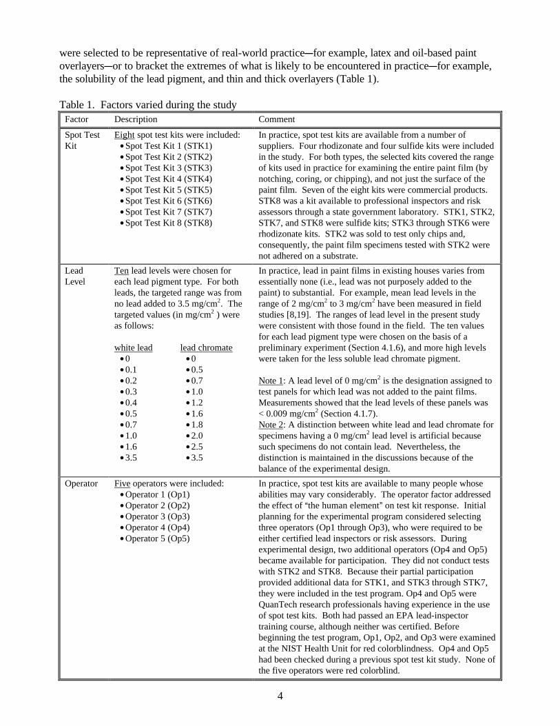
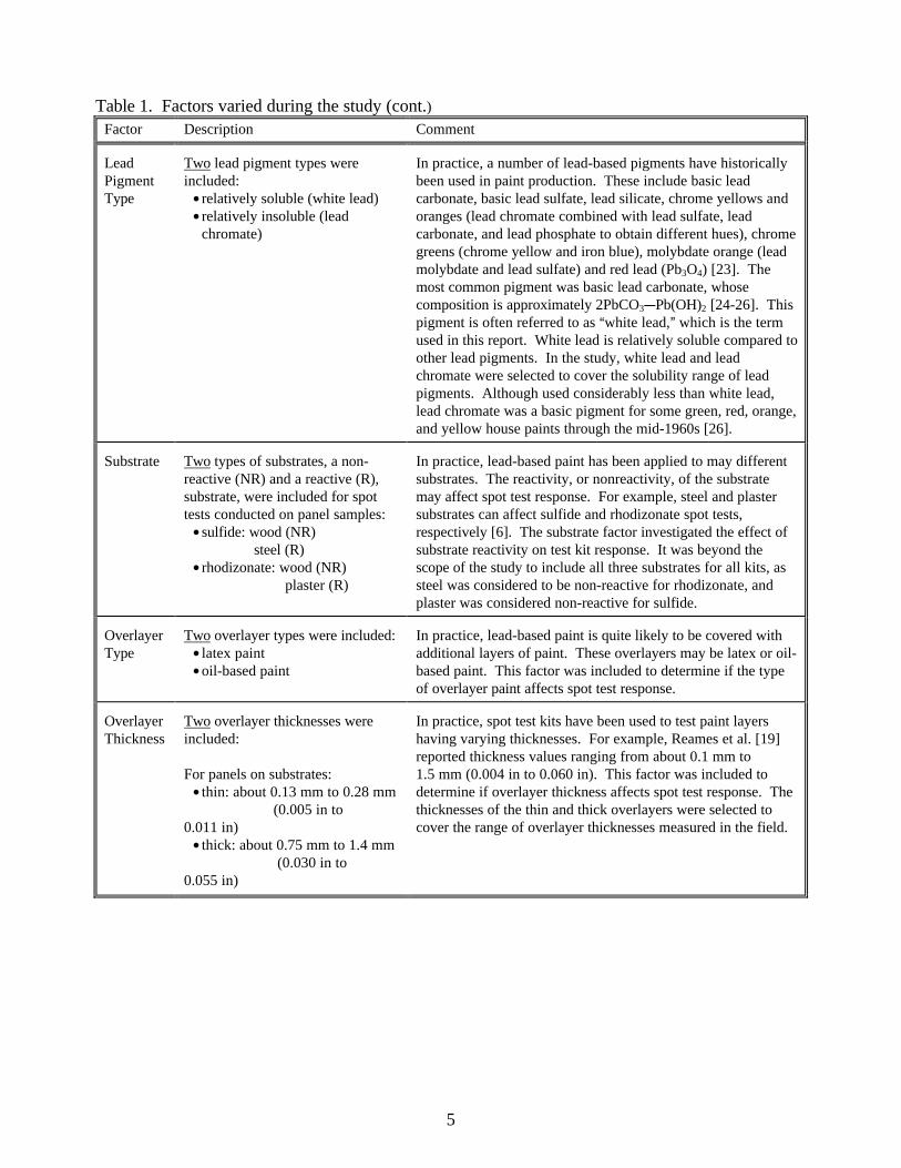
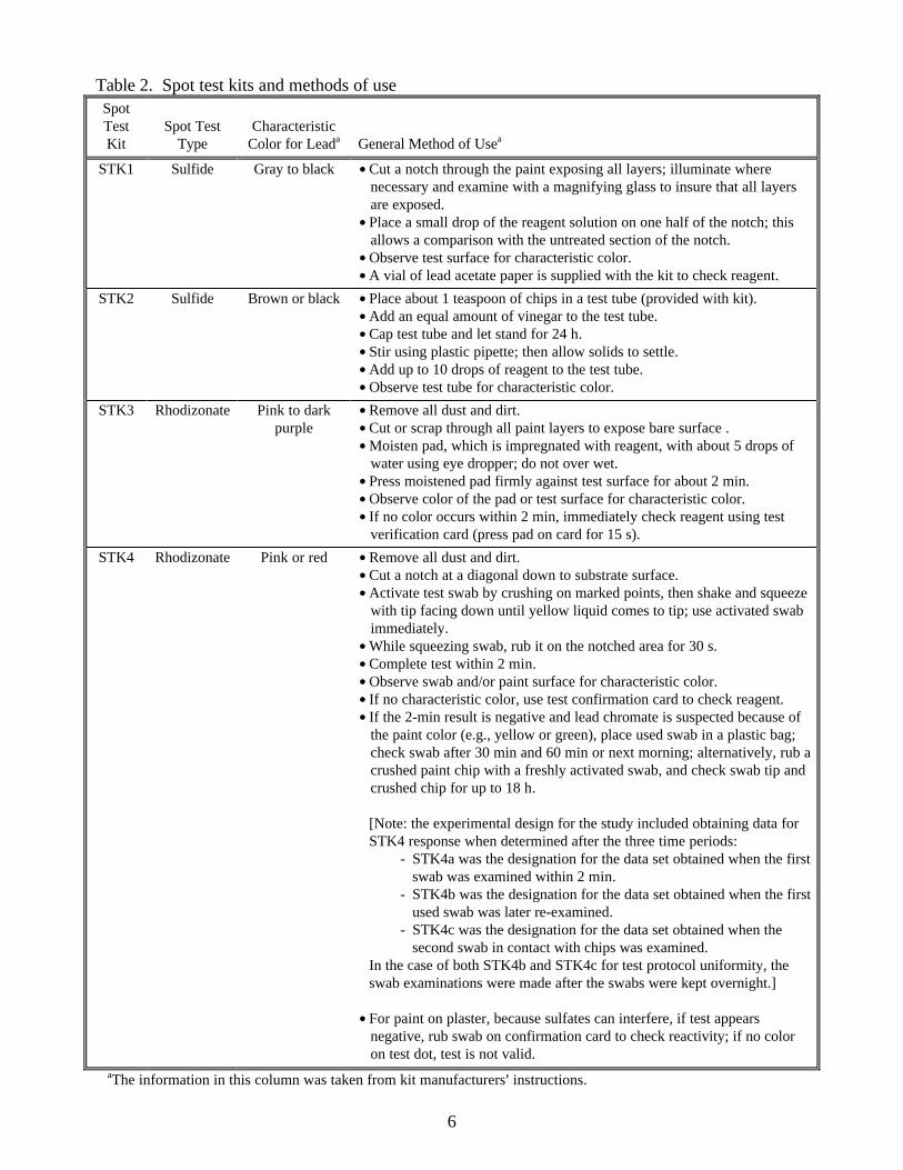


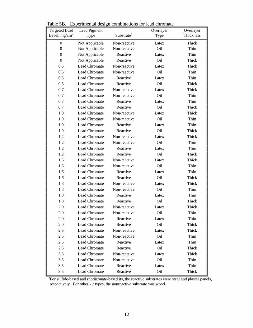
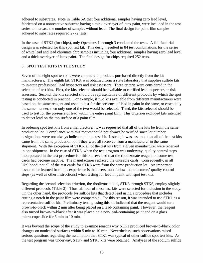

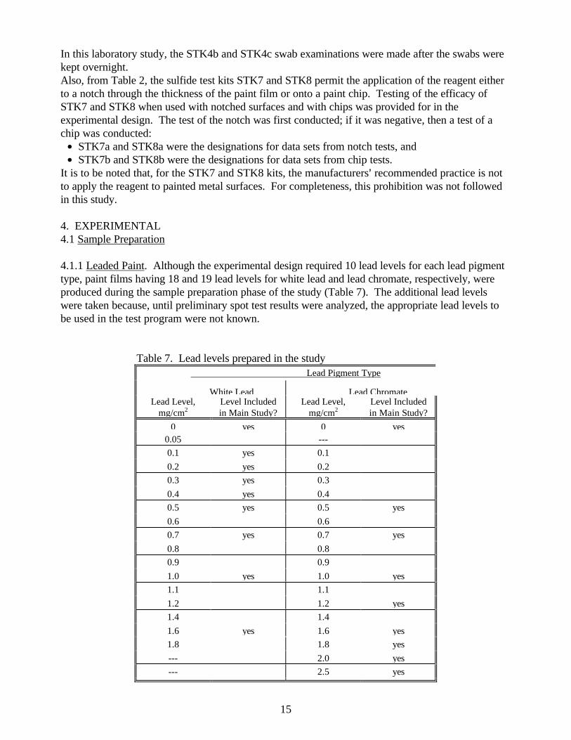


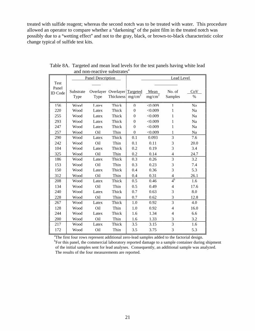
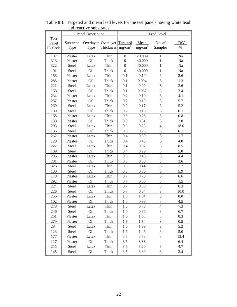


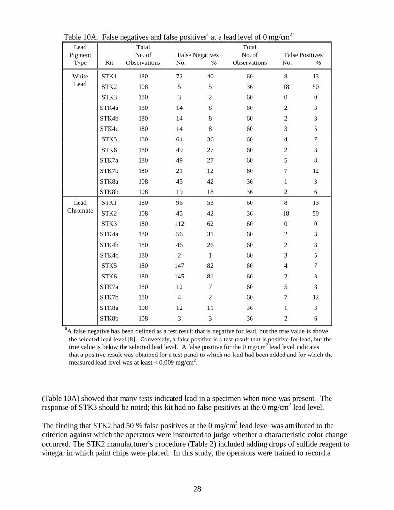


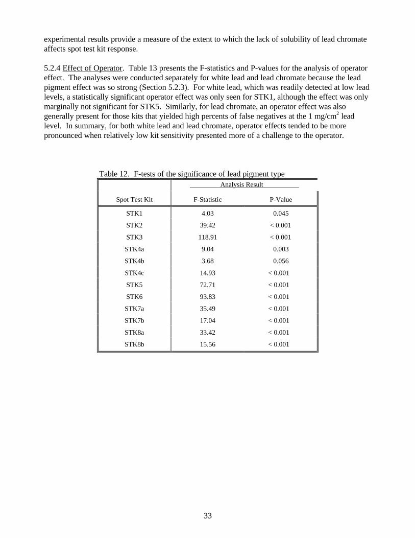


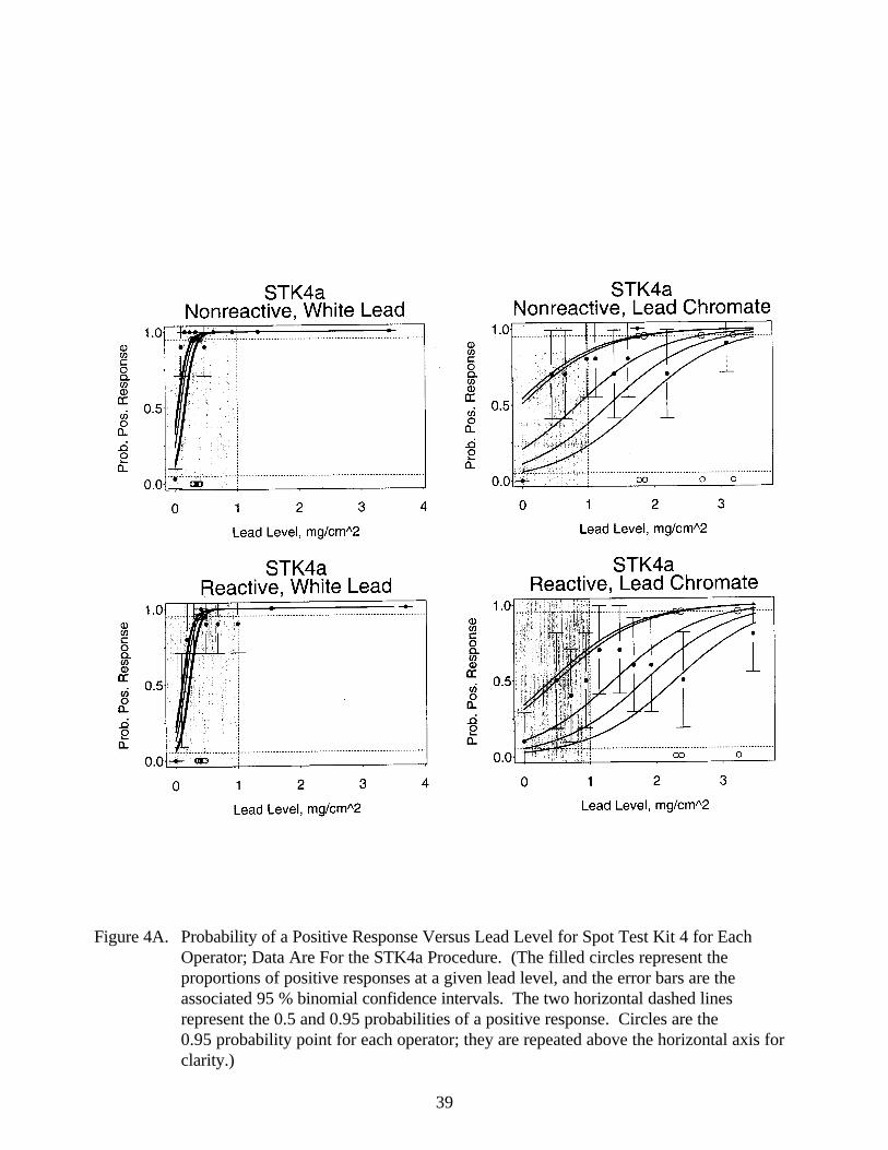


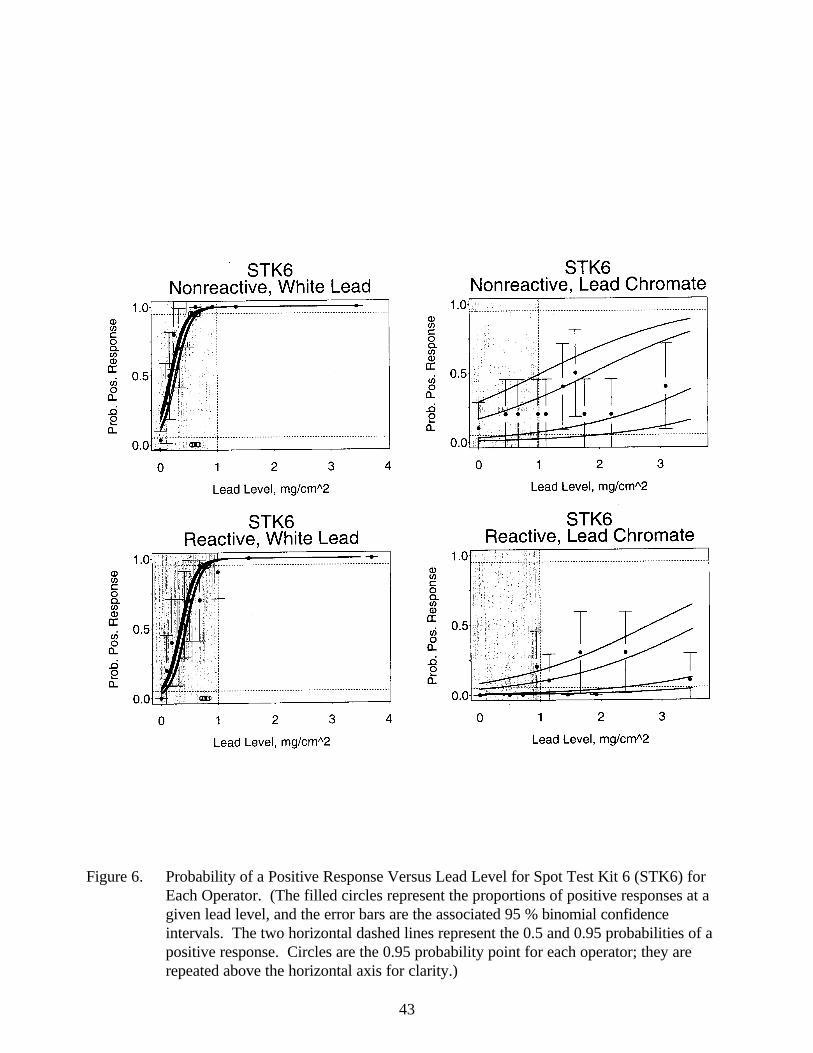
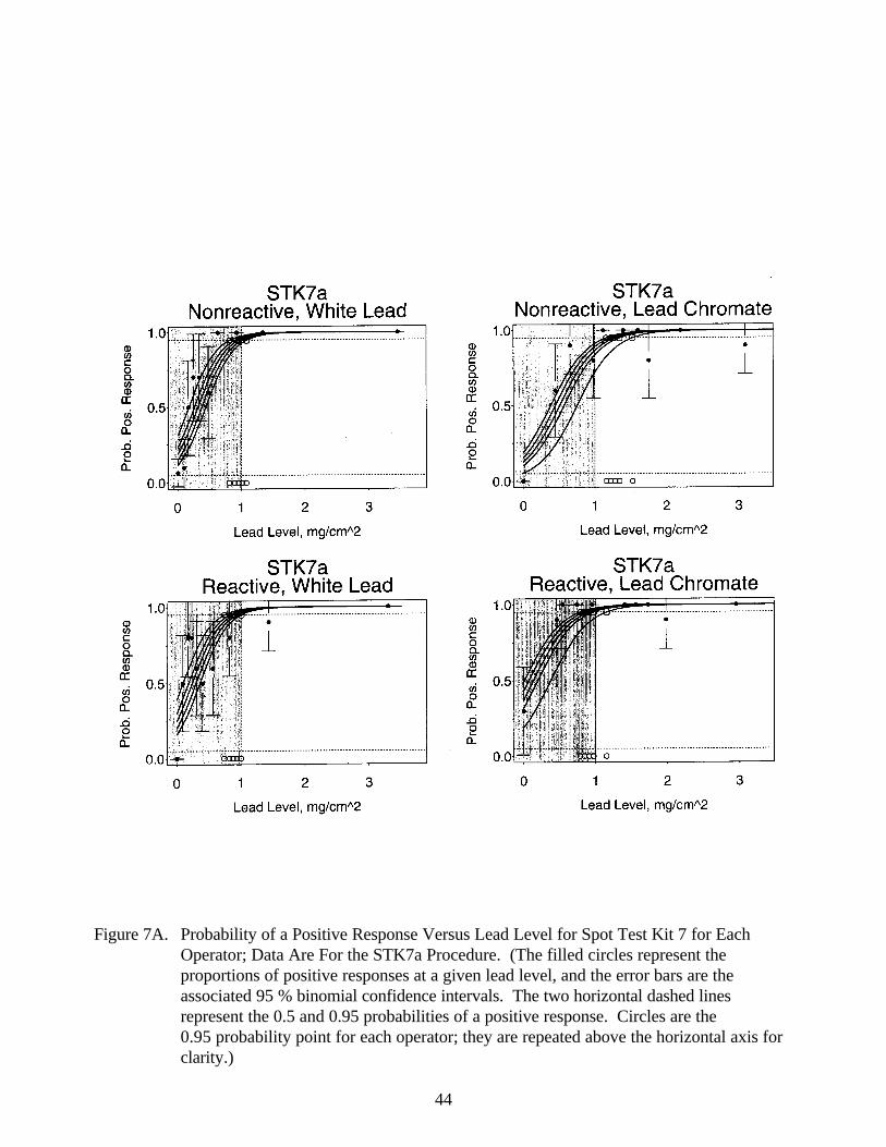


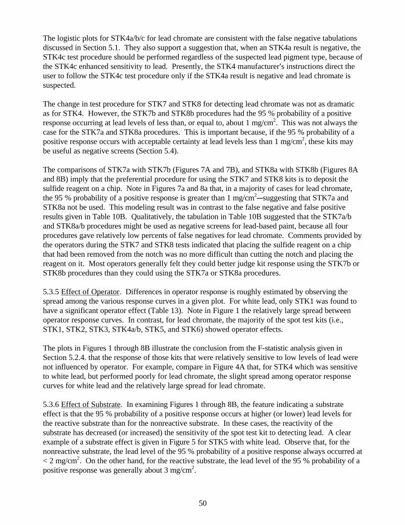


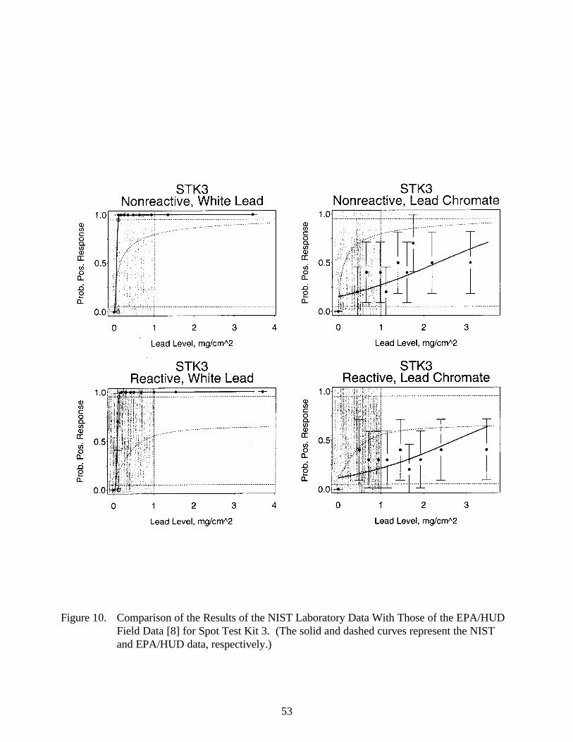


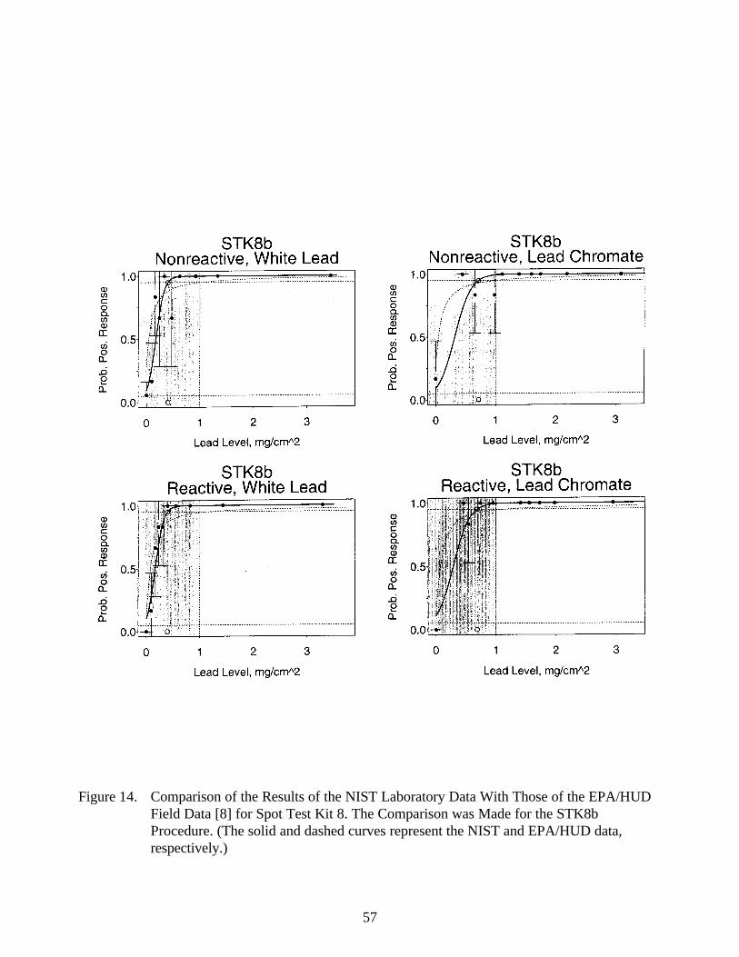
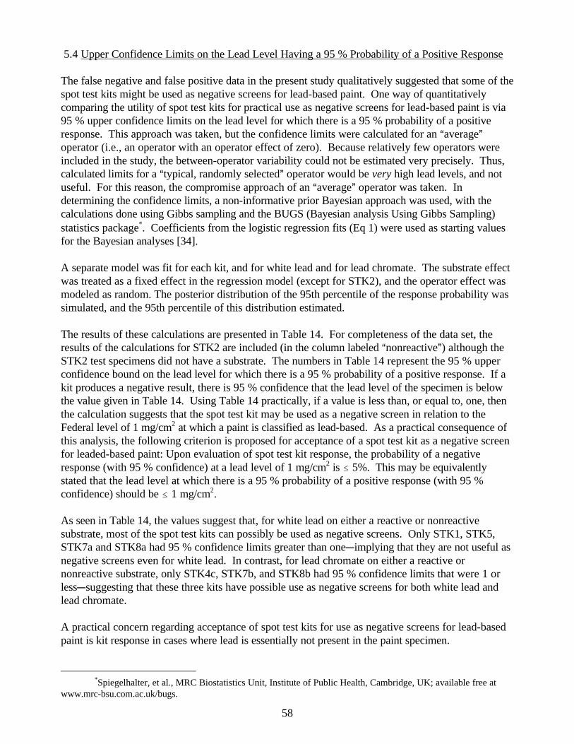


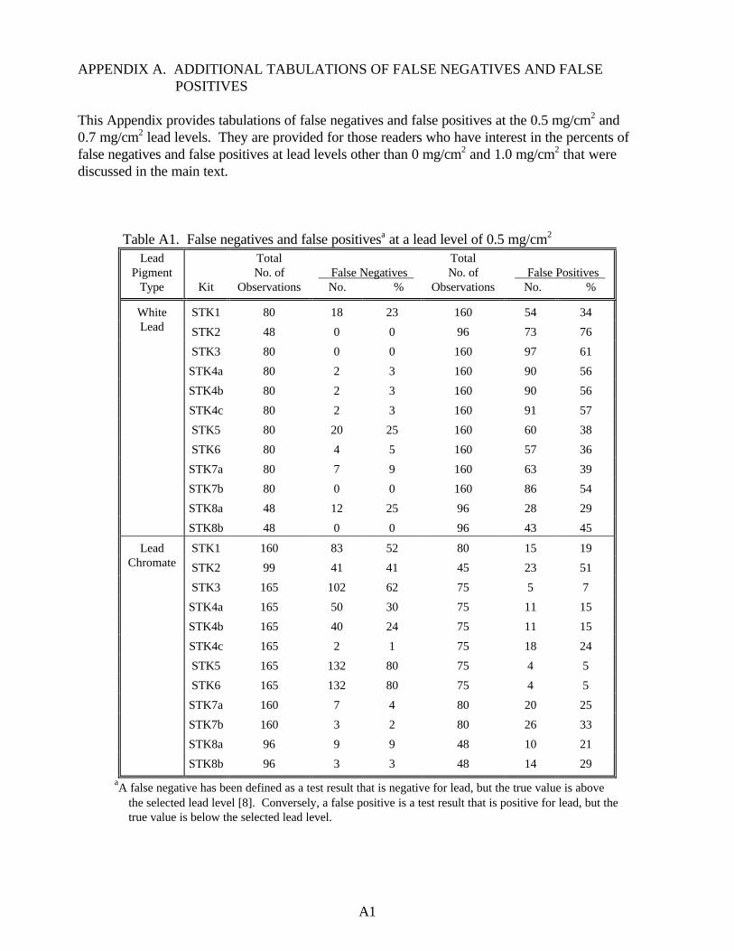


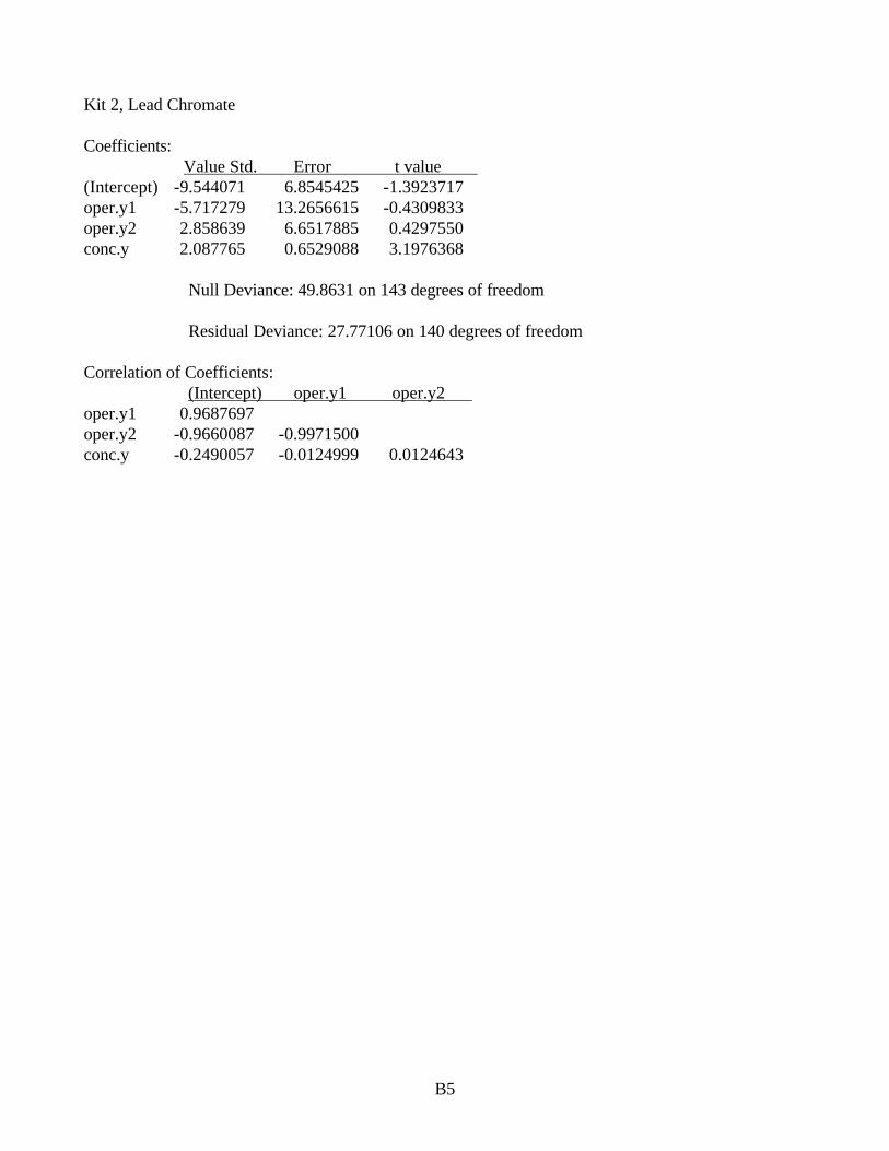


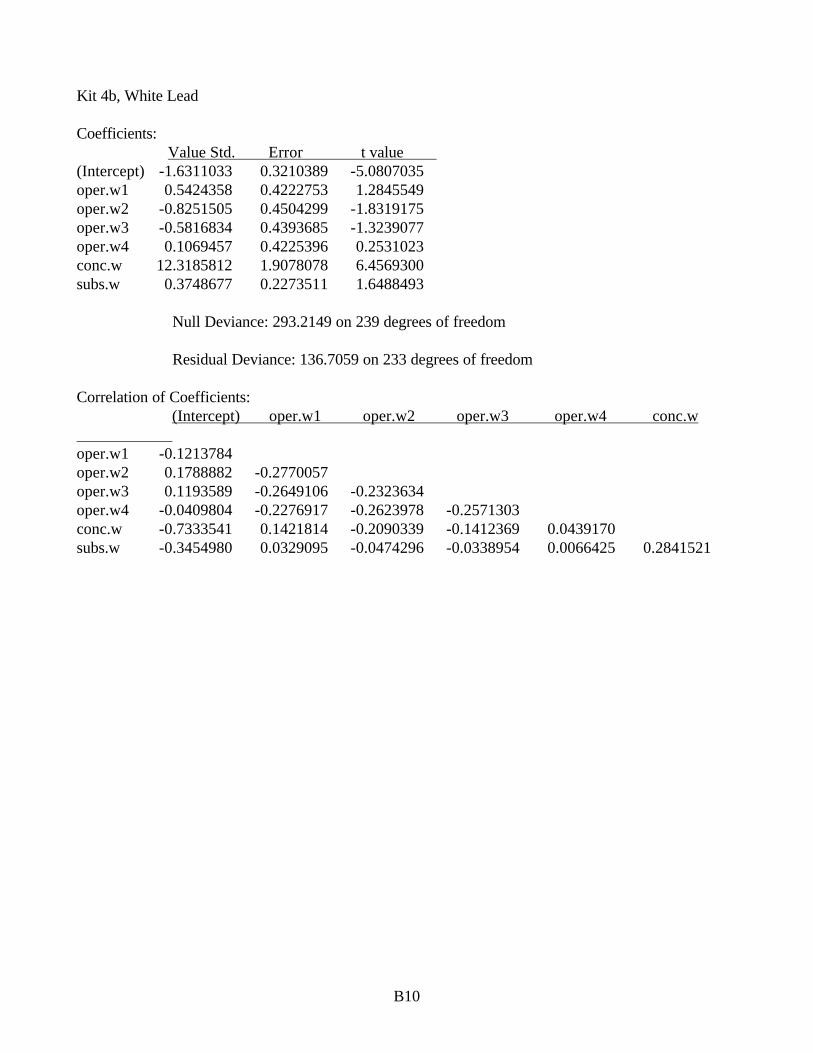

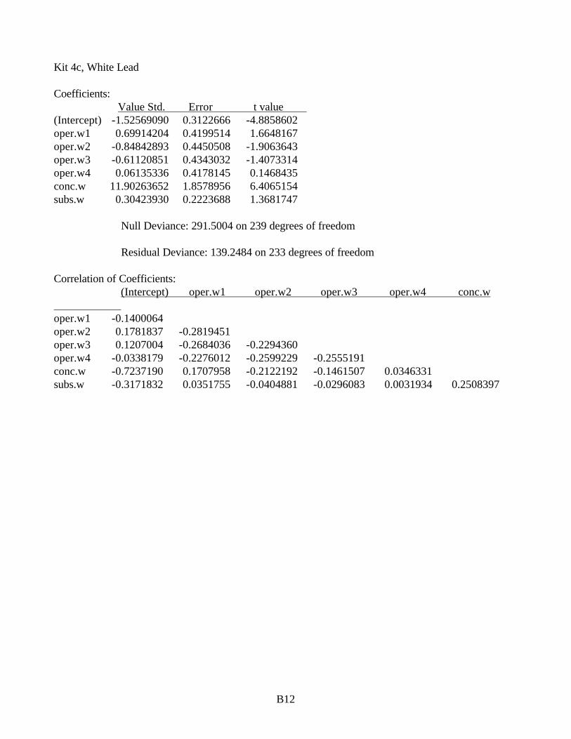
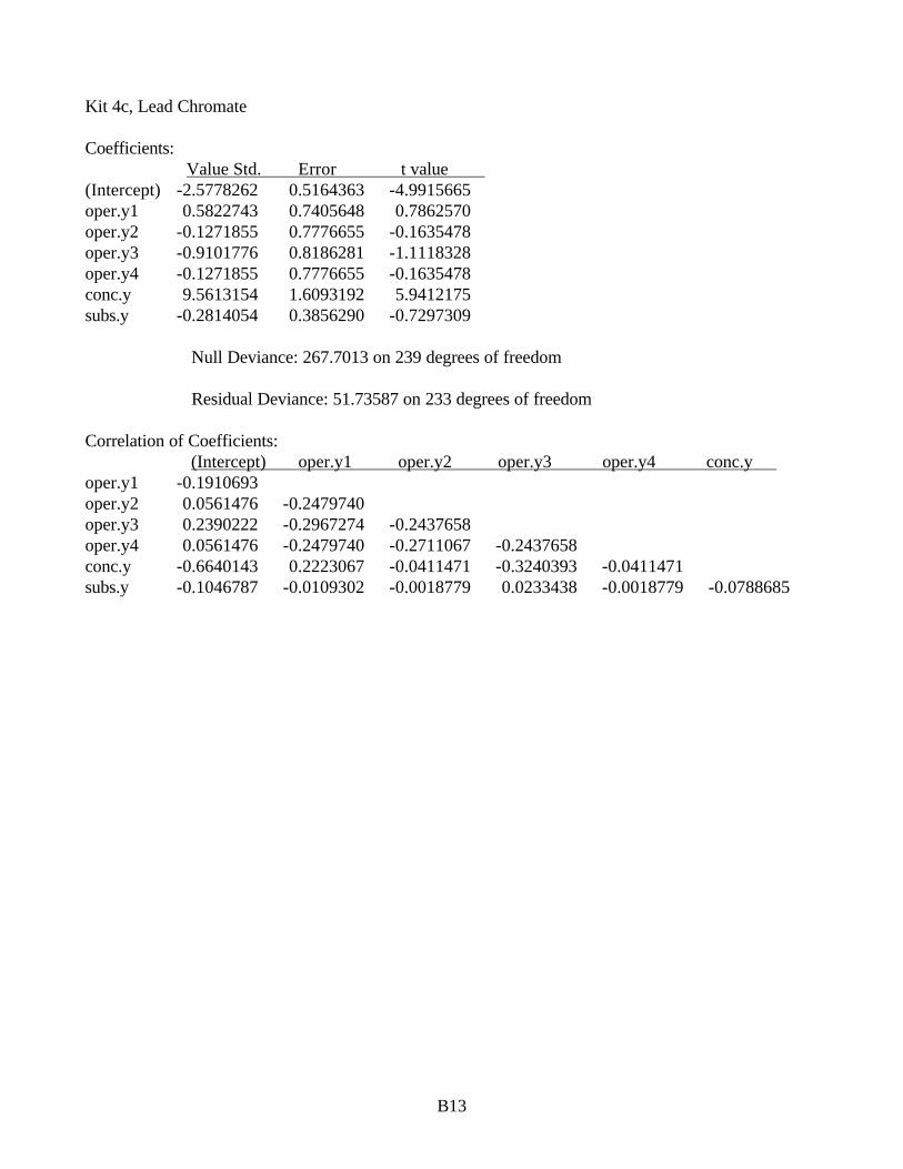


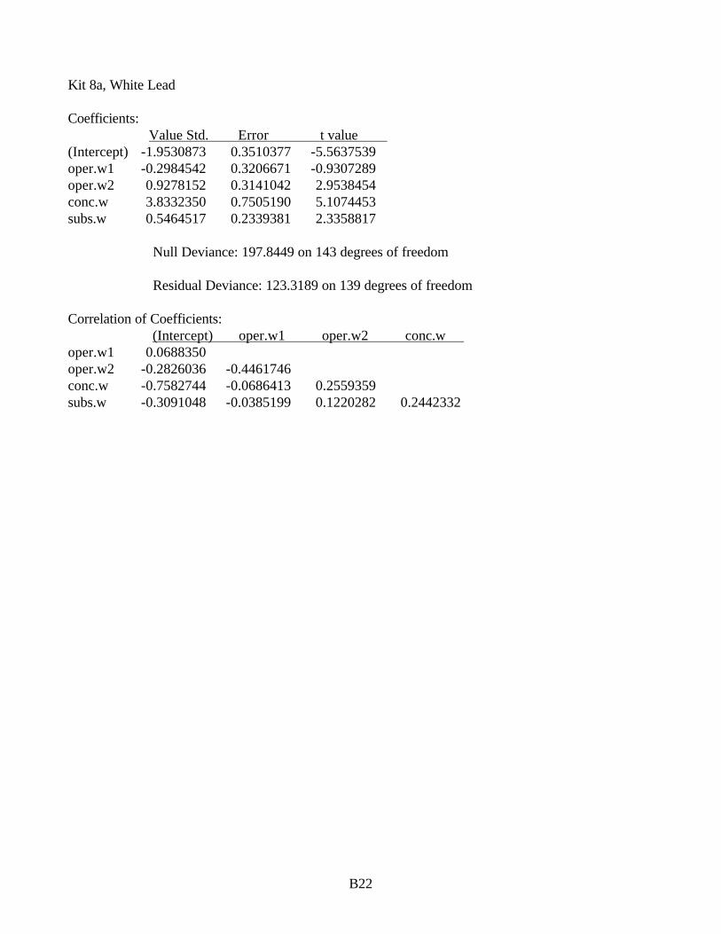
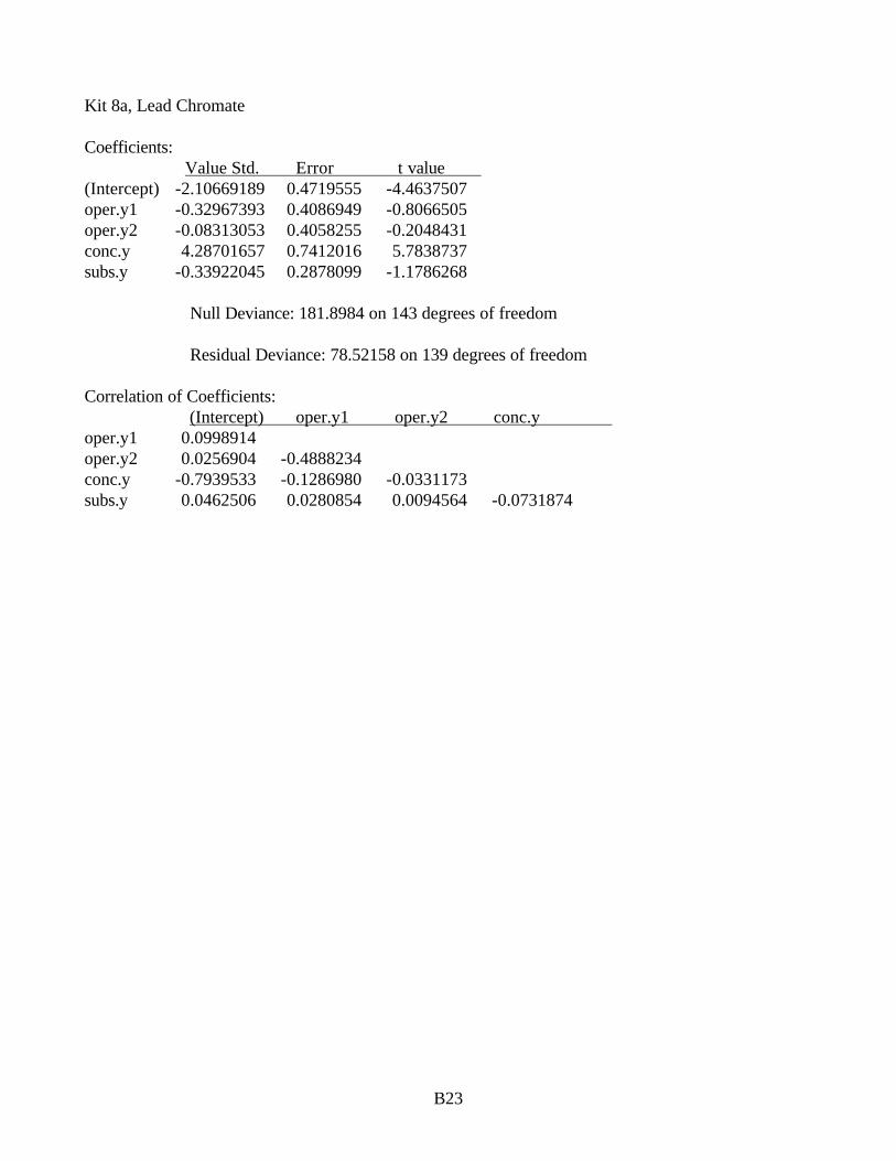


![Detecting Carbon Monoxide Poisoning Detecting Carbon ...2].pdf · Detecting Carbon Monoxide Poisoning Detecting Carbon Monoxide Poisoning. Detecting Carbon Monoxide Poisoning C arbon](https://static.documents.pub/doc/80x56/5f551747b859172cd56bb119/detecting-carbon-monoxide-poisoning-detecting-carbon-2pdf-detecting-carbon.jpg)


