Spray cooling: An assessment for use with automotive power electronics applications Prepared by Desikan Bharathan And Vahab Hassani National Renewable Energy Laboratory 1617 Cole Boulevard Golden, CO 80401 Milestone Report for FY 2005 Prepared under Power Electronics Task FY05-7000 September 30, 2005
Transcript
Spray cooling:
An assessment for use with automotive power electronics applications
Prepared by
Desikan Bharathan And
Vahab Hassani
National Renewable Energy Laboratory 1617 Cole Boulevard Golden, CO 80401
Milestone Report for FY 2005
Prepared under
Power Electronics Task FY05-7000
September 30, 2005
Abstract
Spray cooling of electronic components using dielectric fluids that may be in direct contact with the electronic parts is assessed. Strict requirements for power conversion devices as needed for automotive applications are evaluated. Recommendations for future course of research in this area for thermal control of power electronics are suggested.
Chapter 1. Introduction
Spray cooling of hot surfaces using liquid sprays has been claimed in the literature to yield very high effective heat removal capabilities. This effort focuses on the suitability and applicability of such spray cooling for cooling power electronic components in automotive applications as being developed under the FreedomCAR program.
This effort was carried out as part of the thermal management tasks under the advanced power electronic and electric machines (APEEM) program under the office of renewable energy and energy efficiency of the US Department of Energy.
1.1 Objective
The overall objective is to assess the suitability of spray cooling for heat removal from power electronic components being developed as part of the FreedomCAR effort under DOE.
The overall mission of the FreedomCAR program addresses many components of the vehicle. Achieving the FreedomCAR goals will require the development of new technologies for power electronics and electric machinery. The new technologies must be compatible with high-volume manufacturing; must ensure high reliability, efficiency, and ruggedness; and simultaneously reduce cost, weight, and volume. Key components for fuel cell and hybrid-electric vehicles include motors, inverters/converters, sensors, control systems, and other interface electronics.
One of the specific objectives related to power electronics is to develop automotive integrated modular power modules for power conversion and control. Building blocks to be developed include power switch stages optimized to run newly developed motors, drives, DC/DC converters, advanced controllers and sensors.
The technical targets as specified by the Energy Efficiency Technology Team (EE Tech Team) are summarized below. The FreedomCAR goals and technical targets for 2010 for the electric-propulsion system, as given in Table 1, include the motor, inverter, gearbox, and controller.
Table 1. Goals for Electric Propulsion System for 2010
FreedomCAR Goals Peak power 55 kW for 18 seconds Continuous power 30 kW Lifetime >15 years (150,000
miles) Cost <$12/peak [<$660]a
Technical Targetss3
Specific power at peak load >1.2 kW/kg [<46 kg]a
Volumetric power density >3.5 kW/l [<16 l]a
Efficiency (10 to 100% speed, 20% 90% rated torque)
a)Numbers in square brackets are equivalents for a 55 kW peak-power system.
Of specific interest to this study is the inverter/converter where the electronic chips are expected to generate heat fluxes of up to 250 W per square centimeter of the silicon-based external chip contact surface. Current technology based on silicon chips requires that the chip maximum temperature not exceed 125oC to assure their reliable performance over the required life of 15 years. To reduce the complexity and perhaps the overall cost for the electronic cooling system, the technology team also set other system requirements such as - the coolant to be used will be the same water-ethylene glycol mixture (WEG) that cools the internal combustion engine, and that - this coolant will be available at a return temperature of 105oC.
These requirements as set by the EE Tech team dictate the use of a particular fluid and limit the choices of methods that can be adopted to achieve high heat removal capabilities. However, parallel activities within the APEEM program generated additional tasks to look into technologies that might have the potential to yield substantially higher heat removal capabilities.
Spray cooling and two-phase heat removal methods fall under this category of technologies that could potentially meet the heat removal requirements with greater ease and lower cost.
1.2 Approach
Our initial approach was to attempt to model the spray heat transfer using the commercially available code Fluent. However, we quickly realized that there were severe uncertainties in the specifications for various parameters for simulating such sprays. These begin with 1) the instabilities of the flow and nature of the spray formation, 2) the uncertainty with which the fresh liquid-vapor interface is formed at the spray outlet, and 3) the transient condensation heat transfer that occurs at those surfaces from the vapor
that was generated else where in the domain. The fresh interfaces are quickly covered by a shell of hot liquid on account of the high rate of condensation. Such details dominate the heat transfer and the fluid flow induced within the domain. It is in general difficult to assess the flow and the accompanying heat transfer in the spray formation region. A second area of difficulty arises at the contact zone where the liquid droplets impinge on the hot surface. Depending on the wall superheat, the liquid undergoes a wide variety of behaviors, with large spreading or bouncing and break up. One may have to assume that there is a thin film of liquid that remains in contact with the hot surface on account of the intermittent arrival of spray droplets. In case of high superheat, vapor blankets the hot surfaces once again on an intermittent basis.
At present, there are no adequate models to capture the complexity of spray heat transfer for the present application.
On account of this realization, we confined our efforts to looking into experimental results only. These experiments focus on arriving at the effective heat transfer coefficient for sprays of different liquids aimed at a hot plate of sizes similar to the electronic chips. Of high importance are the variations of the heat transfer coefficient as functions of the liquid spray flow, geometry, and subcooling, and the critical heat flux at which the temperature of the wall rises sharply with increasing heat flux.
We examined the literature to arrive at key results that are most relevant to the present application. Based on those results, we modeled the electronic board assemblies to assess the suitability of sprays for removing high heat fluxes.
1.3 Scope and Limitations
Reported results in this paper are confined to data obtained from the literature. We will attempt to get relevant data when our laboratory will be in operation during the next fiscal year.
Chapter 2. Background
Spray impingement on hot surfaces has the capability to remove large amounts of heat by vaporization. It is considered one of the key technologies for thermal management in many applications.
Spray systems are attractive to cool electronic components because the spray can contact the chips directly, thus eliminating many layer of thermal resistances imposed by the intermediate layers that keep the cooling system separate in indirect cooling. Sprays can also be directed to cool both sides of the chips if packaged suitably. However, difficulties arise because the sprayed liquid should be electrically non-conducting and must be kept pure with adequate filtering to keep metallic particles from being entrained. This requirement severely limits the selection of an appropriate fluid for the spray. Potential for erosion resulting from continual impact of droplets also remains a concern.
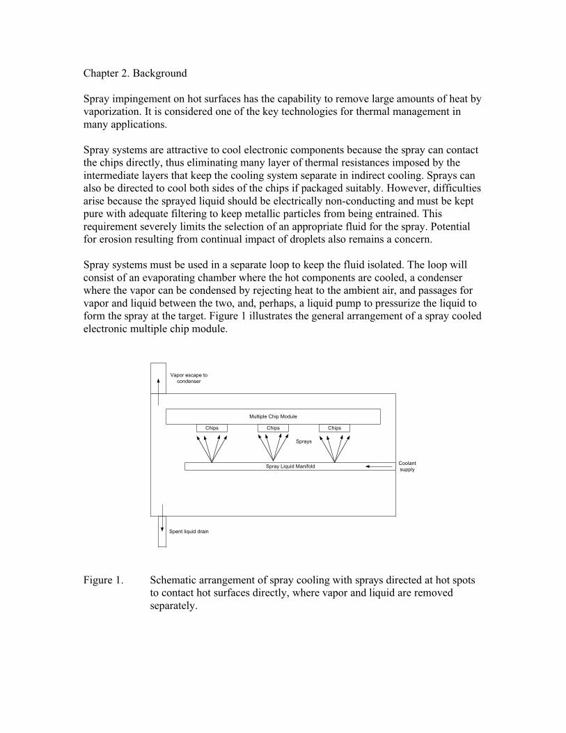
Spray systems must be used in a separate loop to keep the fluid isolated. The loop will consist of an evaporating chamber where the hot components are cooled, a condenser where the vapor can be condensed by rejecting heat to the ambient air, and passages for vapor and liquid between the two, and, perhaps, a liquid pump to pressurize the liquid to form the spray at the target. Figure 1 illustrates the general arrangement of a spray cooled electronic multiple chip module.
supply
condenser
Multiple Chip Module
Chips Chips Chips
Spray Liquid Manifold
Spent liquid drain
Coolant
Vapor escape to
Sprays
Figure 1. Schematic arrangement of spray cooling with sprays directed at hot spots to contact hot surfaces directly, where vapor and liquid are removed separately.
Many publications deal with the formation of sprays. Hydrodynamics and the formation of spray resulting from the instabilities of the flow of two fluids adjacent to each other have been the subject of hundred years of research. For an overview of the subject, see review articles such as Chigier [1996] and Lin [1998].
2.1 On the selection of fluids for spray cooling
One of the key requirements for the liquid used for spray cooling of electronic components is that it be non-conducting or a dielectric. The candidate liquids are few. We summarize their relative merits here.
FluorinertTM are liquids with a high dielectric strength manufactured by 3M Corporation. They are claimed to be practically non-toxic and non-flammable. These are available with molecular masses ranging from 340 to 670, with lower mass compounds yielding higher vapor pressures, and lower densities and viscosities. Many heat transfer studies using one of these liquids, namely, FC-72, have been reported in the literature for electronic cooling applications.
Another series of fluids manufactured by Dow Corning is the volatile methyl siloxanes, labeled the OS series fluids, commonly used as cleaning agents. These fluids possess high volatility and are flammable. These are generally used as cleaning agents and have also been considered as potential coolants for electronics; however, their suitability with electronic cooling is yet to be established. Little information is available on their heat transfer characteristics.
Oakridge researchers have suggested the use of the common refrigerant R134a as a candidate for electronic cooling. They have conducted a series of experiments to establish its feasibility for use with automotive electronics. R134a is commonly used in vehicle’s air-conditioning systems and its use for electronic cooling is likely to be a simple extension. However, the maximum temperature this liquid will be exposed must be limited to maintain system pressures within design limits.
A most common difficulty with the use of these fluids is that their acceptability as “environmentally friendly” must be established for general consumer acceptance. Safety of their use remains the next major concern. Lack of availability of full set of physical property data for these fluids is a drawback as well in their evaluation. Key properties for two-phase applications such as vapor-liquid surface tension, latent heats of evaporation, and vapor and liquid thermal conductivities are needed over the full range of applicable temperatures.
Inability to find a fluid acceptable for consumer’s everyday use in their vehicles may rule out the possibility for the use of spray cooling using these fluids for electronic cooling for automotive applications.
2.2 Heat transfer with dielectric fluids
Early works on spray cooling using Freon-113 were reported by Ghodbane [1991] and Holman [1993]. Droplet velocities ranged from 5.4 to 28 m/s and diameters ranged from 210 to 980 �m. Maximum heat flux attained in the experiments was about 25 W/cm2. Heat source to nozzle distance was approximately 19 cm. They correlated the results as:
) l
qx µ
5.1
hfg = (5.9 We) 6.0 (c ∆T / hfg (1) l
Where q is the heat flux (W/m2); x is the nozzle-target separation distance (m); µl is the
liquid dynamic viscosity (kg/m.s); hfg is the latent heat of vaporization (J/kg).
We is the Weber number and cl is the liquid specific heat (J/kg.K); ∆T is the measured
average wall to liquid temperature difference.
They could not compare their data with others on account of lack of reported information for similar investigations.
Estes [1995] reported the use of FC-72, FC-87, and water for spray cooling applications. Sprays were targeted centrally toward circular targets. They observed that the critical heat flux is accompanied by the onset of vapor blanketing at the edges of the target. They correlated the Sauter mean diameter of the spray as functions of the nozzle Weber and Reynolds numbers. They found that critical heat flux (CHF) was greater for dense sprays.
All tests were done at atmospheric pressure. For FC-72, the saturation temperature was near 57oC. For the three different nozzles that they used, the CHF ranged from 76 W/cm2
to 137 W/cm2. An effective heat transfer coefficient from the hot surface ranged from 1 W/cm2K to about 1.9 W/cm2K, with light sprays yielding higher values. On the average, the heat transfer coefficient for FC-72 sprays amounted to about 1.4 W/cm2K.
Estes [1995] also provide a correlation for the CHF based on the spray characteristics and fluid properties. Among the dielectric fluids evaluated, our analysis using that correlation indicates that, among the dielectric fluids, R-134a yields the highest CHF at working temperatures of around 50oC. The system saturation pressure reaches a value close to 300 psi.
Lin [2003] reports data on spray cooling with FC-87, FC-72, methanol and water. Multiple nozzles impinging multiple heated surfaces were used. For the fluorocarbons, they report a maximum CHF of near 90 W/cm2, with denser sprays yielding higher CHF. An average heat transfer coefficient for the FC-72 data yielded a value of about 1.6 W/cm2K.
Horacek [2005] reports CHF values for FC-72 sprays ranging from 40 to 80 W/cm2.
Pautsch [2005] reports results using FC-72 and a number of different nozzle patterns. They found that highest heat flux removal rates of up to 78 W/cm2 were obtained when phase change is avoided. Multiple nozzles used the liquid ineffectively. HTC values ranged from 0.2 W/cm2K to 1.2 W/cm2K.
No data on the use of mentioned other liquids for spray cooling of electronics are available in the literature at this time.
ORNL is currently working with ISR to assess the use of R-134a and spray cooling for power electronics on an ongoing effort. ORNL has already demonstrated that R-134a can be used in a pool-boiling configuration with electronics immersed in the liquid pool.
Advantages for the use of sprays are that: since spray systems eliminate many layers of thermal resistance, it offers the potential to achieve high heat fluxes at low differential temperatures; since such a system will be independent, it may offer a lower coolant inlet temperature lower than 105oC; sprays can also be used to remove heat from both sides the board and chips.
We conducted numerical simulations were for cooling one phase of the Semikron’s cooling module. We modeled the actual geometry of the IGBT and diode-carrying board, with cooling imposed either only on the chip side or on both sides. FC-72 sprays were directed straight at the heat generating chips. An effective overall HTC of 1.2 W/cm2K is assumed based on the data discussed in the previous section. A maximum heat flux of 50 W/cm2 is imposed on the chips for cooling on one side; in case of cooling applied on both sides this value is doubled. This limit of 50 W/cm2 is considered conservative and falls below the expected CHF to provide adequate safety margin for the application.
Table 2. Summary of modeled cases for spray cooling
50
50
( f ) 100
100 39
100 36
Case Description Load Delta-T
maximum* Remarks
(W/cm^2) (Celsius)
Sprays
( a ) Chip Top Only 50 52.3
( b ) All Top Surfaces 15.3
( c ) Chip Top & Bottom 50 24.5
( d ) All Top & Bottom
Surfaces 12.7
Best case at
low flux
( e ) Chip Top & Bottom 100 39.7
All Top & Bottom
Surfaces 25.5
Best Case at
high flux
Jets
( g ) Low-R Configuration;
Cone bottom only
Uses WEG;
CHF > 500
( h ) Low-R Configuration; All
bottom surfaces
Uses WEG;
CHF > 500
* Maximum chip temperature minus coolant inlet temperature
Attached Table 2 summarizes the various cases for which the simulation was carried out. This table lists the description of the assumed cooling areas and the heat fluxes. The fourth column lists the temperature difference between the maximum chip temperature and the coolant inlet temperature.
Figure 2 shows the typical results of these analyses, in this case for Case (a). Temperature contours are plotted on the external visible surfaces of the chip. Since the top of the chip is the only surface being cooled, it remains at the lowest temperature. The rest of the board achieves a nearly constant temperature of around 112oC. The overall temperature difference amongst the various parts of the board is minimal, however.
As we note from Table 2, the lowest temperature difference of 25.5oC occurs when the board is cooled from both the top and bottom surfaces at the higher heat flux of 100 W/cm2.
Figure 2. Temperature contours for spray cooling using FC-72, with a coolant inlet temperature of 70oC
We also ran a case where the bottom cooling plate is removed totally. For this case, sprays with an effective HTC of 1.2 W/cm2K cooled both sides of the board. The resulting temperature profile is shown in Figure 3. A maximum temperature difference of 26.7oC occurs at the middle of chip locations.
Figure 3. Temperature contours for spray cooling using FC-72 for the board with no cooling plate with a coolant inlet temperature of 70oC
Spray cooling using fluorocarbon liquid FC-72 has the potential to remove heat fluxes of 50 W/cm2 if cooled on one side. If cooled on both sides, with proper packaging heat flux levels of 100 W/cm2 can be achieved. In both cases, adequate margins away from the critical heat flux on the surface of about 70 W/cm2 is provided based on the reported data from the literature.
The spray system with FC-72 requires about a 30oC temperature difference between the chip and the cooling liquid inlet temperature. A limitation on the high temperature of the chip of 125oC will dictate that the coolant inlet temperature should not exceed 95oC. These results are for the use of FC-72 directly on the electronic chips and the board carrying the chips.
Chapter 4. Conclusions and Recommendations
Spray cooling with FC-72 sprays is unlikely to meet the program goal for heat flux removal at a rate of 200 to 250 W/cm2.
Higher potential exists for the use of R-134a as the coolant, based on projected critical heat fluxes. However we lack data on spray cooling heat transfer for this liquid.
One drawback for use of this liquid is that the chamber pressures are likely to be high at high ambient temperatures. Pool boiling data reported by Hseih [2004] suggest a maximum heat transfer coefficient of only about 0.5 W/cm2K. Data using sprays and liquid films are likely to be substantially higher and are needed for assessing their improved performance with R-134a.
Surface enhancements such as micro grooves and grids have been shown in the literature to enhance spray heat fluxes substantially. Such enhancements may be usable on the board side, but unlikely to be used on the chip surfaces.
Surface modifying agents in the liquid have also been reported to enhance spray heat removal capacity, but are not likely to be put in everyday use in consumer maintained items.
Considering that R-134a is already in use automotive air conditioning systems, we recommend that we continue to investigate the use this liquid for electronic cooling. Spray heat transfer using this fluid must be experimentally evaluated. Experiments should be carried out to assess the limits for heat fluxes and effective heat transfer coefficients using sprays directed at hot spots simulating the electronic chips and boards.
Acknowledgements
The authors would like to acknowledge the support provided by Susan Rogers, Technology Development Manager, Vehicle Systems Team, FreedomCAR and Vehicle Technologies of the Office of Energy Efficiency and Renewable Energy of the U.S. Department of Energy.
References
Chigier [1996], Chigier, N. and Reitz, R.D., “Regimes of jet breakup and breakup mechanisms,” in Recent advances in spray combustion: Spray atomization and drop burning phenomena, ed. K.K. Kuo, 1, pp 109-135, Reston, VA. Estes [1995], Estes, K.A. and Mudawar, I., “Correlation of Sauter mean diameter and critical heat flux for spray cooling of small surfaces,” International Journal of Heat and Mass Transfer, 38, pp 2985-2996.
Ghodbane [1991], Ghodbane, M. and Holman, J.P., “Experimental study of spray cooling with Freon-113,” International Journal of Heat and Mass Transfer, 34, pp 1163-1174.
Holman [1993], Holman, J.P. and Kendall, C.M., “Extended studies of spray cooling with Freon-113,” International Journal of Heat and Mass Transfer, 36, pp 2239-2241.
Horacek [2005], Horacek, B., Kiger, K.T. and Kim, J., “Single nozzle spray cooling heat transfer mechanisms,” International Journal of Heat and Mass Transfer, 48, pp 1425-1438.
Hsieh [2004], Hseih, S.S., Fan, T.C., and Tsai, H.H., “Spray cooling characteristics of water and R-134a. Part I: nucleate boiling,” International Journal of Heat and Mass Transfer, 47, pp 5703-5712.
Lin [1998], Lin, S.P. and Reitz, R.D., “Drop and Spray formation from a liquid jet,” Annual Review of Fluid Mechanics, 30, pp 85-105.
Lin [2003], Lin, L. and Ponnappan, R., “Heat transfer characteristics of spray cooling in a closed loop,” International Journal of Heat and Mass Transfer, 46, pp 3737-3746.
Pautsch [2005], Pautsch, A.G., Shedd, T.A., “Spray impingement cooling with single-and multiple-nozzle arrays. Part I. Heat transfer data using FC-72,” International Journal of Heat and Mass Transfer, 48, pp 3167-3175.