' - NUC TP 251 ,Tri, ?NM SPRAY DRAG OF SURFACE-PIERCING STRUTS by Richard B. Chapman Sensor And Fire Control Department September 1971 .SEA fwst 0T 0 C E N-T " ~DD C Approved for public release; distribution unlimited. Roptodu ad by NATIONAL TECHNICAL INFORMATION SERVICE Sptingfield, Va. 22151
Transcript
' -
NUC TP 251
,Tri,
?NM SPRAY DRAG OF
SURFACE-PIERCING STRUTSby
Richard B. Chapman
Sensor And Fire Control Department
September 1971
.SEA fwst
0T 0
C E N-T "
~DD
C
Approved for public release; distribution unlimited.
Roptodu ad by
NATIONAL TECHNICALINFORMATION SERVICE
Sptingfield, Va. 22151
UNCLASSIFIEDSec'urity Classificution
DOCUMENT CONTROL DATA . R & D[Scrursty rtaxsIfirarlon of #lfte body of nb~traot arid ondeXt, dnnotatson nut be entered when the overall report Is chMssilied)
I. ORIGINATING ACTIVITY (Corporate author) Z0. REPORT SECURITY CLASSIFICATION
Naval Undersea Research and Development Center UNCLASSIFIEDSan Diego, California 92132 2b. GROUP
3. REPORT TITLE
SPRAY DRAG OF SURFACE-PIERCING STRUTS
4. DESCRIPTIVE NOTES ('type of report and inclusive dats)
Research and Development5. AU THORISI (First name, middle initial, lait name)
Richard B. Chapman
6. REPORT DATE 7a. TOTAL NO. OF PAGES 7b. NO. OF REFS
September 1971 40 74M. CONTRACT OR GRANT NO. . ORIGINATOR'S R-PORT NUMZSRIS)
Sponsored by the NUC Independent Exploratory and
b. PROJECT No. Development Funds as part of the "[P 251"New Vehicle and Sonar Studies."
C.b. OTHER REPORT NOIS) (Any other numbers that may be assignedthis report)
d.
t0. DISTRIBUTION STATEMENT
Distribution of this document is unlimited.
I. SUPPLEMENTARY NtTES 12. SPONSORING MILITARY ACTIVITY
Naval Material CommandWashington, D. C. 20360
13. ADSACT
-- Spray drags were measured using a series of nine surface-piercing struts operated in fourteen configurations.
Empirical equations were deduced and compared with earlier data. The strut surface-area wetted above the waterlineby the spray sheet was determined from phutographs of various configurations and used as evidence that the frictionaldrag of the spray sheet flowing over the strut was the primary source of the measured spray drag. The mass flow ratecontained in the spray sheet was medsured indirectly. Following these experiments horizontal spray rails were attachedto three of the struts and produced significant reductions in the spray drag of each. ( ,
Details of illustrations inthis document may be better
lNAVAL UNDERSEA RESEARCH AND DEVELOPMENT CENTER, SAN DIEGO, CA. 92132
AN ACTIVITY OF THE NAVAL MATERIAL COMMAND
CHARLES B. BISHOP, Capt., USN Wm. B. McLEAN, Ph.D.
Commander Technical Di-ector
The work reported was done from September to November 1970, and was
sponsored by the NUC Independent Exploratory and Development Funds as part of
the "New Vehicle and Sonar Studies."
Released by Under authority of
T. G. LANG, Head W. D. SQUIRE, Head
Advanced Concepts Group Sensor and FireControl Department
ct SECI G SC 3
i13
...........
5jSMl110f~jJU3L1o WS
GI .AVAIL to./f f11,%
1 1
SUMMARY
PROBLEM
Determine the amount of spray drag acting on surface-piercing struts suitable for
use on a semi-submerged ship and investigate ways of reducing spray drag.
RESULTS
Tests using a series of nine strut models in fourteen configurations resulted inempirical equations for spray drag. Photographs furnished evidence that spray drag isprimarily due to the increased wetted surface area caused by the flow of the spray sheetover the strut surface above the waterline. Struts with blunt leading edges, such as air-foils, caused the spray to climb the strut at a steep angle. The mass flow rate containedin the spray sheet was measured indirectly to illustrate the high drag which could resultfrom the spray striking trailing components of the ship. Horizontal spray rails werefound to reduce spray drag significantly'
RECOMMENDATIONS
Symmetric double-arc struts with thickness to chord ratios of 16 percent or smallerare recommended for semi-submerged ships. Horizontal spray rails are recommended as ameans of reducing spray drag.
I)f
1 )
iii
.4
CONTENTS
INTRODUCTION 1
DESCRIPTION OF THE STRUT MODELS 2
MEASUREMENT OF SPRAY DRAG 2SPRAY DRAG RESULTS 3
COMPARISON WITH PREVIOUS RESULTS 4APPEARANCE OF THE SPRAY SHEET 4
SPRAY DRAG AS A FUNCTION OF WETTED SURFACE AREA 5
SECTION DRAG RESULTS 6
FLOW RATE OF THE SPRAY SHEET 6REDUCTION OF SPRAY DRAG 8
CONCLUSIONS 9
REFERENCES 31
NOMENCLATURE 33
:VIV
INTRODUCTION
Work was done to determine the amount of spray drag acting on a surface-piercingstrut suitable for use on a semi-submerged ship. Means of reducing this drag were also inves-tigated. A semi-submerged ship concept has been recently developed at NUC (reference 1).The ship consists of a pair of totally submerged hulls connected to a platform held abovethe waterline by two pairs of surface-piercing struts. The struts are designed to operate inthe supercritical Froude number range to eliminate wave drag. Wave drag reaches a maxi-mum when the Froude number based on chord length is approximately .5 (reference 2).Wave formation and wave drag drops off rapidly at higher Froude numbers and is replacedby a thin film of water which flows over the strut above the waterline leaving a spray sheetbehind the trailing edge. Data presented in references 2 and 3 indicate that wave drag is neg-ligible and spray drag is independent of Froude number for Froude numbers of about threeor greater. Spray drag can be important at high Froude numbers, and a means of reducingsuch drag is desirable in designing struts for the semi-submerged ship.
A limited amount of previous data on spray drag is available. Hoerner (reference 2)combined his own results with data from Coffee and McKann (reference 4), Kaplan (refer-ence 5), and others to deduce the empirical relationship
Dspray = 0.24qt 2 (1)
for thickness to forebody ratios (x/c) less than about 0.4, and
Dspray = 0.l2qt 2 (2)
for blunter bodies. Savitsky and Breslin (reference 3) measured the spray drags for a seriesof airfoils with t/c = 10, 20, and 30% and x/c = 30%. From their data they deduced
Dspray = 0.03 qct + 0.08qt 2 (3)
Equation (3) results from fitting a straight line for Dspray/qct over a limited range of t/cand does not contain the discontinuity apparent in equations (I) and (2). The spray dragsmeasured by Savitsky and Breslin are clearly greater than those predicted by Hoerner, per-haps because they used relatively blunt airfoils. This difference suggested that strut formmay be an important factor in spray drag. To gain further insight into the problem of spraydrag for various strut forms, measurements were made using a series of strut models.
N
DESCRIPTION OF THE STRUT MODELS
Nine strut models were fabricated from wood. Five of these were also tested withthe direction of flow reversed, making a total of fourteen configurations. The first eightmodels had no angle of rake and six-inch chords. The ninth was raked 450 and had a chordlength of 6V12 -' 8.5 inches. The first eight struts all had t/c ratios of 12, 16, or 21%. Foreach of these three ratios, two struts of the double arc type composed of two pairs of circu-lar arcs were built, a symmetric strut with x/c = 50%, and an asymmetric strut with x/c = 35%or 65% depending on the direction of flow. The other three struts were a 16%-thick strutwith a cusp on one edge and a wedge on the other, a 1 6%-thick 66-series airfoil, and a1 6%-thick symmetric double-arc strut raked 45' to produce an effective t/c of about 11.3%.
w All struts had rounded tips and 0.25-inch wide sandstrips starting 0.75 inches from bothleading and trailing edges. The nonraked struts were all 22-inches long. The strut formsare listed in table 1.
MEASUREMENT OF SPRAY DRAG
The strut models were tested in the Free Surface Water Tunnel at the CaliforniaInstitute of Technology with free-stream velocities of 20, 22, and 24 ft/sec. Based on a6-inch chord these velocities correspond to Froude numbers between 5.0 and 6.0 andReynolds numbers of about 106. These Froude numbers are sufficiently high to assurethat the test data is in the Froude-number-independent region. Since the design Froudenumber for the semi-submerged ship is only about 2.0, a small amount of wave drag andother Froude-number-dependent components may be present in the spray drag of the ship.Velocities near the maximum speed of the tunnel were needed, however, to assure com-plete turbulence behind the sand strips and to minimize the effect of balance sensitivity.The measured values of se,-tion drag on the models indicate that the flow was turbulent.
Each configuration was tested at fifteen or more depths of submergence from aminimum of 3.4 inches. The drag on each strut was found to be a linear function of thesubmerged depth. The slope was identified with the two-dimensional section drag and theintercept was identified with the sum of the changes in drag due to the strut tip and thefree surface. In equation form the relationship is
DtotaI = Xd + Dspray + Dtip (4)
where X is the setion drag in lbs/ft. The tip drag was estimated using an empirical equationfor rounded tips given in reference 2,
LDtip -.02qt 2 . (5)
The negative tip drag is apparently due to the three-dimensional nature of the flow near thetip. This tip drag correction is roughly of the same magnitude as the scatter in the spraydrag data.
2
An empirical formula for tip drag is not as satisfying as an analysis which eliminatestip drag entirely. This is theoretically possible using the pitching moment data. Let P(Z) bethe pitching moment measured at an elevation Z above the waterline. It may be shown that
dP - XZ - Dspray (6)dZ
Although equation (6) is theoretically superior, attempts to apply it were unsuccessful fortwo reasons. First it was necessary to extrapolate over a much greater distance using equa-tion (6) since measurements for small values of Z could not be made without causing thespray to strike the drag balance. In addition, calculation of the first derivative increasedthe scatter in the data.
SPRAY DRAG RESULTS
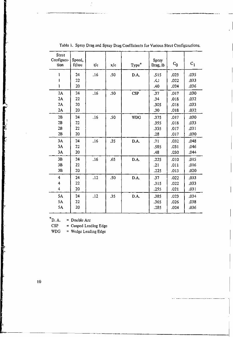
Results of calculations using equations (4) and (5) are listed in table 1. Two spraydrag coefficients are presented, Co, based on the area ct, and C 1, based on the waterplanearea A, an important parameter for the semi-submerged ship. The coefficient CO is plottedagainst t/c in figure 1 for struts of the double arc form. A!so shown are empirical equationsand data from references 2 and 3. A dependence of spray drag on strut form is evident inthe present data. Struts with x/c = 35% produced the most spray drag and struts withx/c = 65% produced the least. Spray drag data for each group of double-arc struts resemblethe airfoil data from reference 3 in form but are closer to the data of reference 2 in mag-
nitude. Lines similar to equation (3) were fitted for each of the three groups of double arcstruts resulting in the following empirical equations:
Co = .003 + .06 t/c when x/c = 65%, (7)
Co = .011 + .08 t/c when x/c = 50%, (8)
and CO = .009 +.013 t/c when x/c = 35%. (9)
These equations are quite rough because of data scatter and the uncertainty of thetip drag estimate. However, they provide engineering estimates over a limited range of t/c.
Both the cusp and the wedge leading edges of strut 2 produce less drag than strut 1.After the waterplane area is taken into account, however, this advantage becomes negligible.The double-arc strut swept 450 appears to offer a savings in spray drag contrary to the con-clusion of reference 4, based on airfoils swept 300, that the spray drag of a swept strutdepends only on its waterplane form.
|A
COMPARISON WITH PREVIOUS RESULTS
The empirical formula of reference 2 is partially based on the spray drags of a13%-thick symmetric double arc tested by Benson and Land, and a 15%-thick asymmetricdouble arc with x/c = 40% tested by Kaplan (reference 5). These strut forms are describedin reference 6. The 13%- and 15%-thick double-arc struts produced CO coefficients of .026and .028 respectively. These values are very close to those predicted by equation 9 andwithin 20% of those predicted by equation 8 Kaplan found that the 15%-thick double arcwas not sufficiently aoymmetric to cause a detectable change in the spray or section dragwhen the direction of flow was reversed. Hoerner also uses measurements apparently madewith 15%- and 30%-thick struts with x/c = 40%. The shapes of these struts were not indi-cated, but they were probably double arcs. The spray drags of these struts were also inde-pendent of the direction of flow. The corresponding value of CO for both thicknesses was.036. This is about 50% greater than predicted by equation (8) for the 15%-thick strut butvery close to the predicted value for the 30%-thick strut. In g .iieral the spray drags inrefereace 1 are larger than predicted by equation (8) but are not inconsistent when experi-mental error is taken into account.
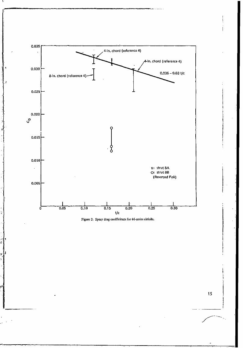
Figure 2 shows the spray drags reported by Coffee and McKann (reference 4) for12%- and 2 1&%-thick 66-series airfoils together with the spray drag measured in the presentexperiment using a 16%-thick airfoil of the same series. Tile much lower spray drag of thereversed airfoil 8B again illustrates the influence of strut form. A unique feature of the66-series airfoil data is that CO decreases as t/c increases. In interpreting this result oneshould perhaps keep in mind the uncertainty introduced by tip drag and the fact that thestruts used by Coffee and McKann had square tips. A straight line fitted through the pointsin figure 2 gives the apprcximate formula
CO = .036 -.03 t/c. (10)
Note that the spray drag of the airfoil is similar to that of the asymm..tric doublearc strut of the same thickness in either orientation. This indicates that spray drag is notsimply a function of x/c but depends on the overall shape.
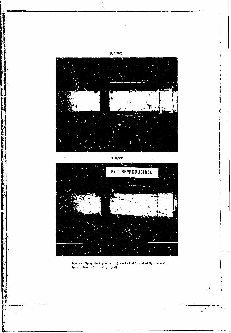
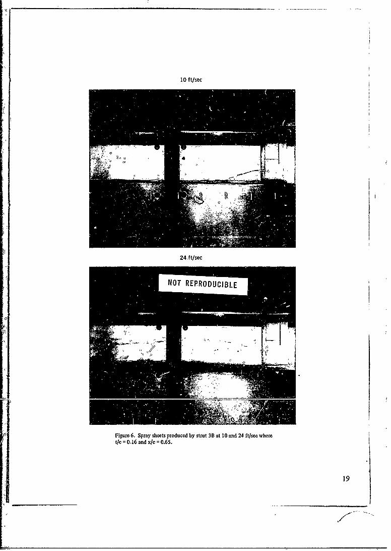
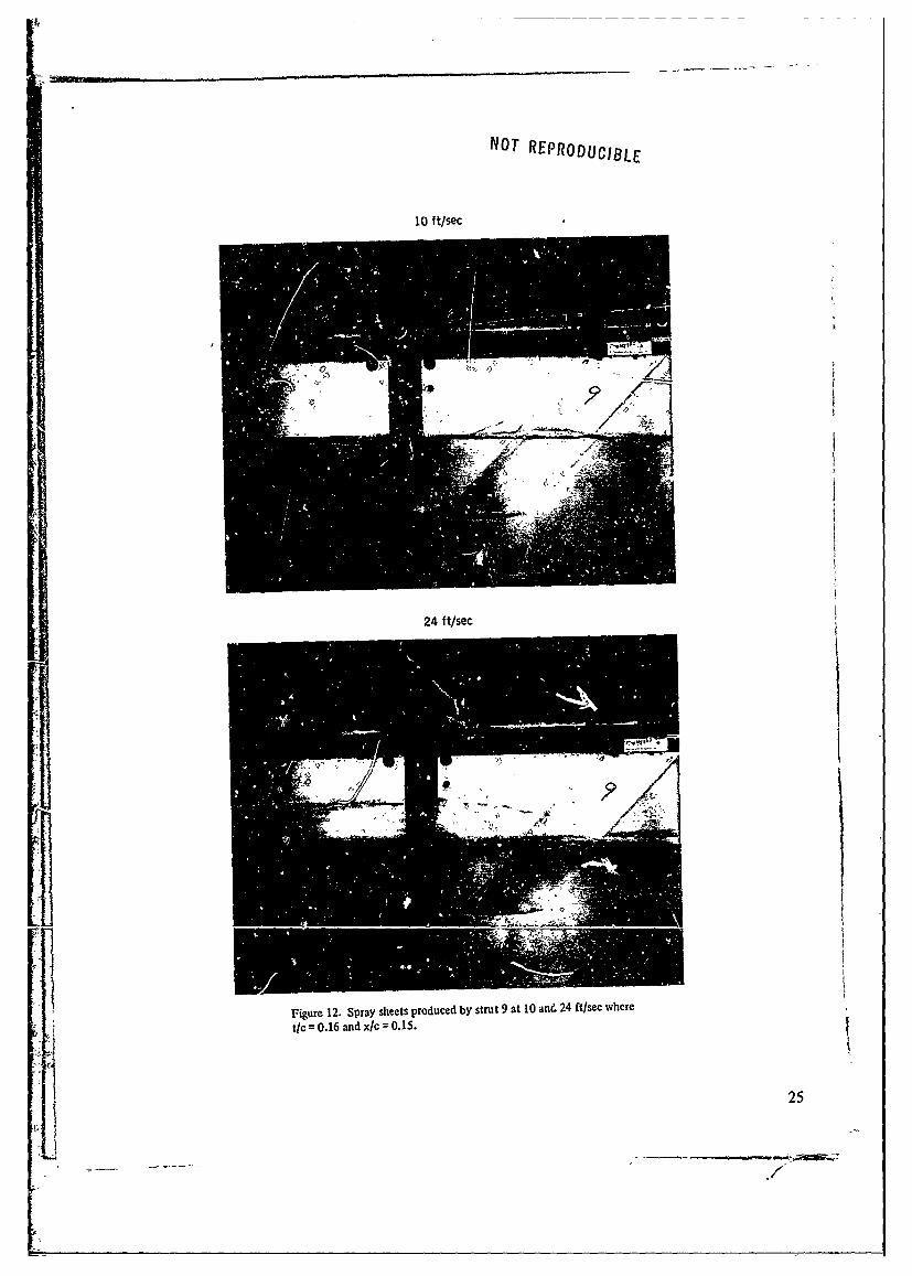
APPEARANCE OF THE SPRAY SHEET
The spray sheets appeared quite different for the various strut configurations.Photographs were made of ten representative configurations. The spray sheets producedat 10 and 24 ft/sec are shown in figures 3 through 12. The spray patterns at 10 ft/sec shouldresemble those on the full-sized ship since the Froude numbers are nearly equal. As thesephotographs show, spray is a somewhat misleading term for the smooth, continuous sheetwhich breaks up only after leaving the trailing edge. Separation of the sheet from the strutwas never observed. The sheet is thickest near the free surface and grows thinner furtherup the strut un" 11 it is terminated by a thick lip of slowly moving liquid believed to resultfrom momentum loss caused by skin-friction. Near the top the sheet is very thin and theliquid may lo3e most of its horizontal velocity and move downward under the influence
of gravity to collect in a lip. This should be most evident at low Froude numbers. The lipis, in fact, more obvious at lower speeds.
Note the differences in the spray sheets formed by the various struts. The sheetformed by the airfoil, figure 11, climbs the leading edge to over half a chord above the water-line. Similar behavior is displayed by sheets formed on airfoils shown in reference 4. In con-trast sheets formed on double arc struts leave the waterline at various angles. Steeper anglesare associated with greater spray drags. Another variation is the cusped strut configuration2A which forms its sheet a small distance behind the leading edge.
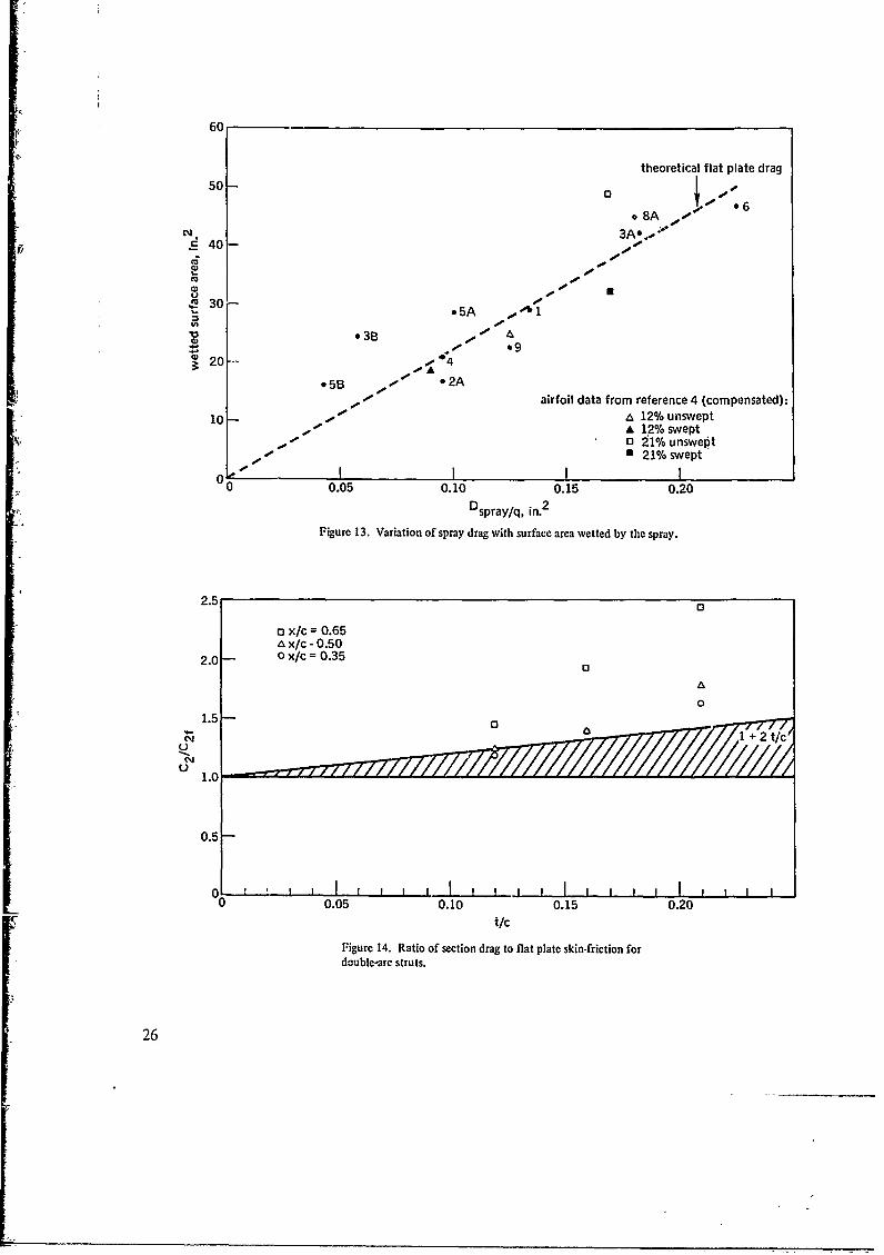
SPRAY DRAG AS A FUNCTION OF WETTED SURFACE AREA
It is evident that strut configurations which produce large spray sheets also havelargc spray drags. This observation is made quantitatively in figure 13 which plots the spraydrag of the photographed configurations at 24 ft/sec against the strut surface area wettedby the spray. Also plotted is the theoretical drag for turbulent flow at 24 ft/sec over aflat plate with a six-inch chord and surface area equal to the area wetted by the spray. Inaddition to experimental scatter there are a number of mechanisms which could cause thespray drag to depart from this value.
1. The horizontal component of the sheet velocity will not always equal the freestream velocity.
2. Flow of the spray sheet may not be fully turbulent.3. Another drag mechanism is associated with the upward momentum imparted to
the spray sheet. The corresponding flow energy is dissipated when the spray strikes thefree surface behind the strut.
4. Although there is no evidence of spray sheet separation, the spray sheet maycontribute some pressure drag above the waterline.
5. At small distances below the waterline the flow will not be purely two-dimensional. The spray may have a favorable effect of relieving pressure drag near thefree surface. This effect may contribute to the low values of spray drag measures onstruts with x/c = 65%.
Despite all these possible mechanisms, the total area wetted by the spray sheetappears to be the controlling factor in the spray drag of all photographed struts with thepos': '-- exceptions of configurations 3B and 5B. Note that the small spray drag coefficientof the swept strut, 9, can be explained by the small wetted surface area. In fact, strut 9has more spray drag per wetted surface area than most other configurations. Assume that
an unswept strut of the same waterplane form produces a spray sheet similar to the sweptstrut. Then it can be determined from the photograph that an additional, roughly triangularsection of strut surface would be covered by the spray sheet, increasing the wetted area byabout 35%. This would explain the difference between the spray drag coefficients for theswept strut 9, and the unswept strut 4, which has a similar waterplane form. This advan-tage might not be present, however, for struts such as airfoils which cause the spray toclimb the strut's leading edge.
5 I
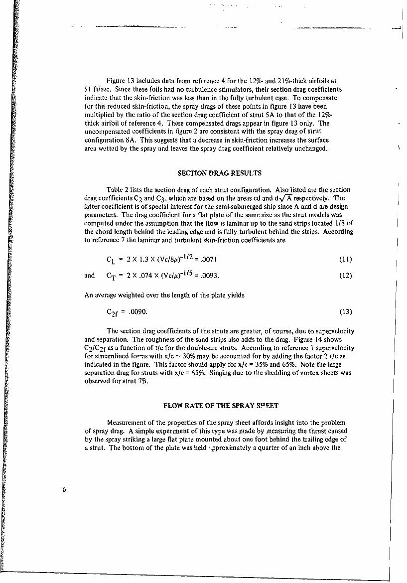
Figure 13 includes data from reference 4 for the 12%- and 2 1%-thick airfoils at5 1 ft/sec. Since these foils had no turbulence stimulators, their section drag coefficientsindicate that the skin-friction was less than in the fully turbulent case. To compensatefor this reduced skin-friction, the spray drags of these points in figure 13 have beenmultiplied by the ratio of the section drag coefficient of strut 5A to that of the 12%-thick airfoil of reference 4. These compensated drags appear in figure 13 only. Theuncompensated coefficients in figure 2 are consistent with the spray drag of strutconfiguration 8A. This suggests that a decrease in skin-friction increases the surfacearea wetted by the spray and leaves the spray drag coefficient relatively unchanged.
SECTION DRAG RESULTS
Table 2 lists the section drag of each strut configuration. Also listed are the sectiondrag coefficients C2 and C3 , which are based on the areas cd and dv/"A" respectively. Thelatter coefficient is of special interest for the semi-submerged ship since A and d are designparameters. The drag coefficient for a flat plate of the same size as the strut models wascomputed under the assumption that the flow is laminar up to the sand strips located 1/8 ofthe chord length behind the leading edge and is fully turbulent behind the strips. Accordingo to reference 7 the laminar and turbulent skin-friction coefficients are
CL = 2 X 1.3 X (Vc/8p)- 1/ 2 = .0071 (11)
and CT = 2 X .074 X (Vc/)" 1/ 5 = .0093. (12)
An average weighted over the length of the plate yields
C2f = .0090. (13)
The section drag coefficients of the struts are greater, of course, due to supervelocityand separation. The roughness of the sand strips also adds to the drag. Figure 14 showsC2/C2f as a function of t/c for the double-arc struts. According to reference 1 supervelocityfor streamlined for-Is with xlc - 30% may be accounted for by adding the factor 2 t/c asindicated in the figure. This factor should apply for x/c = 35% and 65%. Note the largeseparation drag for struts with x/c = 65%. Singing due to the shedding of vortex sheets wasobserved for strut 7B.
FLOW RATE OF THE SPRAY SPEET
Measurement of the properties of the spray sheet affords insight into the problemof spray drag. A simple experiment of this type was made by ineasuring the thrust causedby the spray striking a large flat plate mounted about one foot behind the trailing edge ofa strut. The bottom of the plate was held -.pproximately a quarter of an inch above the
6
waterline. Measurements for each strut model were made at velocities of 20 and 24 ft/sec.In all cases the plate was ahead of the point where the spray would attain its maximumheight in the absence of the plate. Of course a portion of the sheet leaving the trailingedge at a low angle and close to the waterline might fall back into the stream beforestriking the plate, but this portion is of little interest.
Table 3 lists the thrust T on the plate caused by spray sheets formed by each strutconfiguration. This thrust should equal the momentum flux of the spray striking the plate.Comparison with spray drags measured on the same struts indicate that spray drag can makea significant reduction in the momentum of the spray sheet, particularly for the thinnerstruts, but enough momentum is left to create a large pressure drag on any object the spraymay strike. Also listed is the mass rate of flow M calculated using the approximation thatspray drag is entirely due to slowing the spray sheet below the free stream velocity V. Then,the mean velocity of the spray leaving the strut is
V' = TV/(T + Dspray) (14)
and the mass rate of flow is
M = (T + Dspray)/V. (15)
The mass flow appeared to be concentrated in the lower portion of the spray sheet.The mass rate of flow of roughly the upper three-quarters of the sheet formed at 24 ft/sec bystrut 2B was measured by capturing the stream in a bucket. About 1.5 lbs/sec entered thebucket, indicating that the lower quarter of the sheet contained about half of the mass flow.
The mass rate of flow is nearly independent of strut form despite the wide range offorebody lengths. A coefficient based on strut thickness,
CM = M/p Vt 2 , (16)
is presented in table 3. This coefficient should be a function of t/c and the Froude number.As shown in figure 15, the data is well represented by
CM = 3.7 Ft/c = 3.7 Vt/cvN . (17)
It should be emphasized that this empirical equation is based on a very limited range ofdata. It is reasonable, however, to expect CM to increase with Froude number in the super-critical range. Then skin friction will have a proportionally greater influence on the flow ofthe spray sheet at lower Froude numbers.
It is possible to estimate the drag caused by the upward acceleration of the spray.If M is the mass rate of flow and h is the mean maximum height attained by the fluidelements of the spray, this contribution to the drag is
II
Dv =MT/V'. (18)
71
In all cases this drag is a small fraction of the measured spray drag. For example,M = 3.4 lbs/sec and V' = 20 ft/sec for strut I at 24 ft/sec. A generous estimate forlh is simplyhalf the maximum height of the spray. An h of five inches results in a drag of about 0.07 lbs.
REDUCTION OF SPRAY DRAG
Strut drag, a combination of spray drag and section drag, may be minimized by aproper choice of the strut form. Struts as thick as 2 1% can be eliminated, but for fixedwaterplane area and depth of submergence, the symmetric double-arc struts with t/c = 12%and 16% are nearly equivalent. With the exception of the swept strut, no strut form testedoffers a significant advantage over strut 1. Struts with x/c = 65% are of little practical valuedue to high section drag and other undesirable effects. However, the relationship betweenspray drag and the surface area wetted by the spray suggests that drag can be reduced with-out altering the basic strut form by adding a device designed to reduce the wetted surfacearea. Three types were tested: vertical separation strips, a spray plate, and horizontal sprayrails. Only the spray rails were successful in reducing drag.
A brief test was made with a pair of 1/8-inch thick vertical strips located two inchesahead of the trailing edge of strut configuration 3A. The strips were able to separate thespray sheet from the strut as intended but did not reduce drag. This was probably becauseadditional pressure drag was exerted on the strips and the surface area wetted by the spraywas reduced by only slightly more than one third.
A large flat plate was attached to strut 1 parallel to the flow, creating a spray shield.This did not appear to reduce the total wetted surface area since the spray sheet covered theunderside of the plate in a pattern very similar to the flow over the strut in the absence ofthe plate. No measurable change in drag was observed.
Then, a series of spray rails was added to strut 1. Each rail was a 1/8-inch-thickwood strip steamed to conform to the strut and faired at both ends. The~rails were mountedparallel to the flow with their centerlines 3/4-inches apart. A single rail was sufficient toturn the spray as shown in figure 16. These rails produced a substantial reduction in spraydrag. In figure 17 the drag at 20, 22, and 24 feet per second on strut 1, both with andwithout rails, is plotted against the elevation of the upper edge of the strut. At 24 ft/sec amaximum reduction of .35 lb of drag occurs when the lowest set of rails is about 5% of thechord above the waterline. At an elevation of 20% of the chord, the savings is about 25 lbs.
Later, 1/16-inch-thick plastic rails were glued on struts 3 and 8, which were thentested in configurations 3A and 8A. Results are shown in figure 18. Ventilation was moresevere when these rails were submerged since they were not faired. These rails reduced dragbut not as mu h as those on strut 1. The maximum savings in both cases was about .25 lb.It was not determined whether the smaller drag reduction was due to the thinner rails or wascharacteristic of the strut forms; it is possible that attachment of a spray rail to a relativelyblunt strut form, such as strut configurations 3A or 8A, causes water to pile up near thefront of the strut and then separate, causing a pressure drag. In any case it is evident thatthe net effect of spray rails is to reduce drag.
8
CONCLUSIONS
The results of this investigation of the spray drag produced by fourteen strut con-figurations are briefly summarized in this section.
I. Spray drag is partially dependent on strut form as well as strut thickness. Strutswith blunt leading edges tend to produce more spray drag.
2. Empirical equations were deduced for several strut series in the region.12 < t/c < .21. For double arc struts they are
Dspray = .003 qct + .06 qt2 when x/c = 65%,
Dspray = .011 qct + .08 qt2 when x/c = 50%,
and Dspray = .009 qct +. 13 qt 2 when x/c = 35%.
The equation for the 66-series airfoil is
Dspray = .036 qct-.03 qt 2 .
3. A cusped leading edge decreases spray diug but does not produce an advantagefor a fixed waterplane area. Sweeping a double arc strut decreases the spray drag for agiven waterplane area by decreasing the surface area wetted by the spray.
4. Skin-friction due to the wetting of the strut surface by the spray sheet is theprimary source of spray drag.
5. The mass rate of flow in the spray sheet depends on t/c and the Froude numberbut not on x/c. However, blunter bodies send the spray up at higher angles wetting morestrut area. Blunt sections are, therefore, not recommended for semi-submerged ships.
6. The losses caused by the upward acceleration of the spray contributed only asmall fraction of the total spray drag of slender struts at moderate Froude numbers.
7. The momentum in the spray sheet is sufficient to create a large pressure dragon any object it may strike.
8. Horizontal spray rails can produce a substantial reduction in spray drag.
9
$!
'A;,
9
.7/
i
Table 1. Spray Drag and Spray Drag Coefficients for Various Stnt Configurations.
1.50 1.40 1.30 1.20 1.10 1.00 0.90 0.80 0.70Elevation, ft
Figure 17. Effect of spray rails on drag of strut 1.
29
0 Z c0
.- 4
c'Ja4
0cc)
-4
.2ccM U'
00
04
C60
4))
too0
000
30-
REFERENCES
1. S. F. Hoerner. Fluid-Dynamic Drag, published by the author, 1965.
2. Davidson Laboratory Report 1192, Experimental Study of Spray Drag of SomeVertical Surface-Piercing Struts, by D. Savitsky, J. P. Breslin. December 1966.
3. Naval Undersea Research and Development Center. Technical Publication NUCTP-235, Naval Feasibility Study of the NUC Semi-Submerged Ship Concept,Part I: Introduction, General Characteristics, and Summary (U), by T. G. Lang.UNCLASSIFIED
4. National Advisory Committee for Aeronautics. NACA Technical Note 3092,Hydrodynamic Drag of 12 and 21 Percent Thick Surface-Piercing Struts, byC. W. Coffee, R. E. McKann. December 1953.
5. Stevens Institute of Technology. Stevens ETT Report 488, Tests of Surface-Piercing Struts,.by P. Kaplan. April 1953.
6. Gibbs and Cox, Inc. Gibbs and Cox Technical Report Number 15, Some Charac-teristics of Spray and Ventilation, by S. F. Hoerner. September 1953.
7. H. Schlichting. Boundary Layer Theory, McGraw-Hill, 1960.
31
NOMENCLATURE
c chord length
t strut thickness
x distance from leading edge to point of maximum thickness(forebody length)
q dynamic pressure, /2p V2
p density of water, 1.94 slugs/ft3
V free stream velocity
Dtotal total drag on the strut
Dspray spray drag
Dtip tip drag
Dv drag caused by the upward acceleration of the spray
X section drag/depth of submersion
d depth of strut tip below the waterline
P pitching moment of strut
Z elevation of balance above waterline
A area of strut in the plane of the undisturbed free surface,waterplane area
CO spray drag coefficient, Dspray/qct
C1 spray drag coefficient, Dspray/qA
CI section drag coefficient, X/qc
C3 section drag coefficient, X/q
CL laminar component of skin-friction for two-sided plate
CT turbulent component of skin-friction for two-sided plate
C2 f skin-friction coefficient for flat plate strut
T thrust of spray striking plate
VI mean velocity of spray striking plateM mass rate of flow of spray