61
Springfield Township, Bucks County, PA Springtown Source Water Protection Plan January 2006 SSM File 103402.0001

Springfield Township, Bucks County, PA
Springtown Source Water Protection Plan
January 2006
SSM File 103402.0001
Springtown Source Water Protection Plan Prepared for: Springfield Township 2320 Township Road Quakertown PA 18951 January 2006 Prepared by: SPOTTS | STEVENS | McCOY Eric P. Grindrod, PG, Manager
Copyright 2006 SSM File 103042.0001

Springfield Township, Bucks County, PA
Springtown Source Water Protection Plan
Table of Contents Executive Summary ............................................................................................................................. 1 1.0 Introduction ............................................................................................................................. 3 2.0 Wellhead Protection Steering Committee and Public Participation .................................. 5 3.0 Delineation of Source Water Protection Areas..................................................................... 7
3.1 Description of Water Supply System........................................................................ 7 3.2 Hydrogeologic Model ............................................................................................... 7 3.3 Model Software......................................................................................................... 8 3.4 Model Inputs ............................................................................................................. 8 3.5 Groundwater Withdrawal........................................................................................ 12 3.6 Model Results ......................................................................................................... 13 3.7 Source Water Protection Area Delineations ........................................................... 14
4.0 Contaminant Source Inventory............................................................................................ 17 4.1 Overview of Contamination Sources ...................................................................... 17 4.2 Contaminant Source Inventory ............................................................................... 19 4.3 Source Water Protection Area Land Use Assessment ............................................ 21
5.0 Source Water Protection Area Management Plan ............................................................. 22 5.1 Plan Components .................................................................................................... 23 5.2 Regulated Uses for the Source Water Protection Zones......................................... 24 5.2.1 Zone I - Regulated Uses.......................................................................................... 24 5.2.2 Zone II - Regulated Uses ........................................................................................ 25 5.2.3 Zone III - Regulated Uses ....................................................................................... 25 5.3 Land Conservation and Nutrient Management ....................................................... 26 5.4 Public Education ..................................................................................................... 26
6.0 Contingency Plan................................................................................................................... 28 7.0 New Water Supply Source Protection ................................................................................. 29
103402.0001

List of Tables
Cooks Creek Discharge and Recharge Rates........................................................................ Table 1 Volumetric Water Flow Budget ...................................................................................................Table 2 Land Uses and Their Relative Risk to Groundwater ...................................................................Table 3 Potential Sources of Contamination Inventory.............................................................................Table 4 Schedule and Cost of Management Activities..............................................................................Table 5 Schedule of Regulated Land Uses ................................................................................................Table 6
List of Figures
Location Map ..............................................................................................................................Figure 1 Hydrogeologic Flow Model ........................................................................................................Figure 2 Digital Elevation Model ..............................................................................................................Figure 3 Geologic Map ..............................................................................................................................Figure 4 Hydraulic Conductivity Map.......................................................................................................Figure 5 Potentiometric Surface Map ........................................................................................................Figure 6 Hydrogeologic Flow Model - Computed vs. Observed Head Values .........................................Figure 7 Source Water Protection Area Delineation Map .........................................................................Figure 8 Groundwater Flow Direction Map .............................................................................................Figure 9 Potential Sources of Contamination ..........................................................................................Figure 10 New Source Area Map ..............................................................................................................Figure 11
103402.0001

List of Appendices
Hydrogeologic Model and Data Package ............................................................................. Appendix A Zone I and Zone II Properties................................................................................................Appendix B Model Wellhead Protection Ordinance .................................................................................Appendix C Public Education Brochure................................................................................................... Appendix D
103402.0001

Springfield Township, Bucks County, PA
Springtown Source Water Protection Plan
Executive Summary
Springfield Township has initiated a source water protection program for the Village of Springtown.
The project was funded through the assistance of a source water protection grant from Pennsylvania
Department of Environmental Protection (PADEP). The program participants include a steering
committee of local and regional stakeholders and a technical committee of environmental
professionals. The goal of the wellhead protection program is the creation of a management plan that
addresses specific concerns and potential threats to the quality and quantity of the public water
supply. This report summarizes the components of the wellhead protection program and includes the
necessary elements for PADEP approval.
1. Steering Committee
A steering committee was formed to provide information, offer guidance, and implement the
wellhead protection activities.
2. Public Participation
Public participation was encouraged through informational and education activities conducted
throughout the program.
3. Source Water Protection Area Delineations
The source water protection areas were delineated for the single well and three groundwater
springs with a hydrogeologic computer model.
4. Potential Sources of Contamination
An inventory of potential sources of contamination within the delineated wellhead protection
areas was generated and evaluated through a susceptibility analysis to assess the risk to
groundwater quality.
5. Management Approaches
Based on the wellhead protection area delineations and potential sources of contamination
inventory, a wellhead protection area management plan was developed with an emphasis on land
use planning and public education.
103402.0001 1

6. Contingency Planning
The source water protection plan will be incorporated into the Springfield Township Emergency
Response Plan.
7. New Source Protection
Springfield Township has identified potential locations for new water supply wells if needed.
The wellhead protection management of the potential new source well(s) is incorporated into the
wellhead protection program and management plan for the existing wells.
The implementation of this source water protection management plan will be carried out through a
joint effort of Springfield Township and neighboring Lower Saucon Township, which includes part of
the protection area for Springtown’s water supply.
103402.0001 2

1.0 Introduction
Springfield Township, Bucks County has initiated a wellhead protection program for the water supply
for the Village of Springtown. The Springfield Township Authority applied for and received a source
water protection grant (ME3511172, May 2002) from the Pennsylvania Department of Environmental
Protection (PADEP). After the grant was awarded, Springfield Township took over the obligations of
the Authority; in January 2004, the Township directed the Springfield Township Environmental
Advisory Council (STEAC) to proceed with development of the plan. Lower Saucon Township,
located north of Springtown, supported the grant; part of Springtown’s source water protection area
lies within Lower Saucon Township. The goal of the plan is to provide management options to
Springfield Township and Lower Saucon Township to protect the public water supply through
regulatory (zoning restrictions) and non-regulatory (public information and education) means.
Springtown is a located along the northern boundary of Bucks County, in the 30-square-mile Cooks
Creek Watershed. Although the township is primarily agrarian, the major traffic corridors of
Pennsylvania State Routes 212 and 412 pass through the Springtown area. The source of
Springtown’s water supply is a single groundwater well and two springs in the Cooks Creek
Watershed (Figure 1). The watershed has been designated as an Exceptional Value Cold Water
Fishery under the Pennsylvania Chapter 93 Water Quality Standards and is the only wild brown trout
and native brook trout fishery in Bucks County. Cooks Creek flows easterly to the Delaware River.
Springfield Township recognizes the importance of protecting Springtown’s water supply. This
awareness is heightened by known septic system failures, aging infrastructure, and development
pressure. This source water protection program provides Springfield Township with a means to
determine the wellhead protection zones and develop a wellhead protection management plan that
meets PADEP program requirements. This plan is consistent with the goals of the Cooks Creek
Watershed Conservation Plan, the Cooks Creek Watershed Monitoring and Management Plan and
the Bucks County Natural Resources Plan that emphasize the importance of water resources and
source water protection for sustaining healthy and productive communities.
The Safe Drinking Water Act (SDWA) Amendments of 1996 established requirements that each state
develop a source water assessment and protection program to evaluate all drinking water sources -
groundwater and surface water - that serve public drinking water supplies and provide a mechanism
for development of local protection programs. The requirements for the wellhead protection program
103402.0001 3

were adopted by PADEP as regulations (Title 25, Chapter 109). This report describes the following
tasks, as recommended by PADEP:
• Formation of a steering committee representing local government entities, water supply
customers, farming and business community representatives,
• Encouragement of public participation through informational and educational activities,
• Delineation of wellhead areas using scientific models to determine the source of the water from
the wells and springs,
• Inventory of potential sources of contaminants to the raw water,
• Development of a wellhead protection area management plan to protect the water supply from
potential contamination as part of a strategic long-term program,
• Preparation of a contingency plan for emergency response and alternate sources, and
• Preparation of a new water supply source protection plan for future needs.
The benefits of the source water protection program affect not only the customers of the public water
supply but also individual well owners within the protection zones. Because groundwater and surface
waters are connected in one water cycle, all users within the watershed benefit from source water
protection.
103402.0001 4

2.0 Wellhead Protection Steering Committee and Public Participation
A steering committee was formed to allow stakeholder input for the source water protection plan.
These members provided information and guidance, and made recommendations for developing the
Source Water Protection Management Plan. The members included representatives of Springfield
Township, the Springfield and Lower Saucon Township Environmental Advisory Councils, residents,
and Cooks Creek Watershed Association. The technical work was conducted by consultants Spotts,
Stevens and McCoy, Inc. (SSM).
The Wellhead Protection Steering Committee chairman is Scott Douglas, chairman of the STEAC,
(610) 346-1604. The Steering Committee members are:
• Scott Douglas – Springfield Township Environmental Advisory Council
• Karen Freeh – Springfield Historical Commission
• Pete Lamana – Springfield Township Supervisor
• Cindy McCurdy - Springfield Township Environmental Advisory Council
• Jeff Mease – Springfield Township Zoning Officer
• Laura Ray – Lower Saucon Township Environmental Advisory Council
• Hans Reimann – Cooks Creek Watershed Association
• Pete Sleeman – Springfield Township Environmental Advisory Council
Other representatives invited to participate and review the plan include:
• Ben Greeley, PG, Pennsylvania Department of Environmental Protection
Technical Committee members responsible for project components include:
• Eric Grindrod, PG, Project Manager, SSM
• Al Guiseppe, PG, Groundwater Modeling and WHPA Delineation, SSM
• Amy Munson, EIT, Public Education, SSM
Wellhead Protection Steering Committee Meetings were held at the Springfield Township Municipal
Building, 2320 Township Road, Quakertown, PA 18951 at the following times.
103402.0001 5

• September 27, 2004 - 7:30 p.m.
• November 11, 2004 - 7:30 p.m.
• January 13, 2005 - 7:30 p.m.
• March 10, 2005 - 7:30 p.m.
• May 12, 2005 - 7:30 p.m.
• July 7, 2005 - 7:30 p.m.
The purposes of the meetings were to distribute public information, gather public input, coordinate
local activities, and interact with government agencies. The most critical responsibility of the
steering committee was to guide and monitor the implementation of the source water protection plan
and support its role throughout other planning activities in the Township. Opportunities for public
participation were provided during the project through attendance at steering committee meetings.
Copies of the approved Source Water Protection Management Plan will be held at the Township
building on Township Road for public review.
103402.0001 6

3.0 Delineation of Source Water Protection Areas
A significant purpose of the PADEP source water protection grant is to assist municipalities and
public water suppliers in obtaining the technical data and analysis required to make informed
management decisions. The source water protection areas were determined using a steady-state
hydrogeologic flow model consistent with PADEP guidance. Details of the hydrogeologic model
construction, calibration and results are included in Appendix A. The summary of the approach and
resulting protection areas are described below.
3.1 Description of Water Supply System
The Springtown Village Well (Well 2) is located on the Springtown Community Volunteer Fire
Company Number 1 property. The well is 158 feet deep and constructed with 95 feet of eight-inch
diameter steel casing. The producing formation is the Leithsville Formation. Currently, the well
system is capable of providing a flow rate of between 100 and 150 gallons per minute. Based on the
year 2004 production volumes, the well contributed an average of 12,900 gallons per day with a
maximum daily production of 61,800 gallons (July 2, 2004).
In addition to the village well, the Springtown water system is fed by three springs located in Lower
Saucon Township. The spring boxes are named Main Spring 1, Spring 2, and Spring 4. Spring 3 has
not been operational for many years, and there are no plans to bring Spring 3 online at this time.
Spring 4 was disconnected in 2003 at the request of DEP due to data suggesting that the source was
being influenced by surface water. When it was connected to the system, Spring 4 provided 10 to 15
gallons per minute. The remaining two springs produce an average flow rate of 20 to 25 gallons per
minute. All three springs produce groundwater from a crystalline rock aquifer (felsic to mafic
gneiss). Based on the year 2004 production volumes, the spring system contributed an average of
44,600 gallons per day with a maximum daily production of 67,200 gallons (August 18, 2004).
3.2 Hydrogeologic Model
Spotts, Stevens and McCoy, Inc. personnel constructed and calibrated a steady-state hydrogeologic
computer model to assess the groundwater flow system in the Springtown project area. The model
incorporated data presented in the Cooks Creek Watershed Conservation Plan and the Cooks Creek
Watershed Monitoring and Management Plan to provide a holistic view of the groundwater flow
103402.0001 7
regime. In addition to providing the delineations of the source water protection areas, the model
offers the townships a planning tool to be used in mitigating water resource-related issues.
A hydrogeologic flow model is a numeric simulation representing groundwater flow with
mathematical equations. The flow simulation takes a complicated natural system and simplifies it to
its basic components. Although the model is constructed from real-world data (e.g., ground surface
elevation, stream location, and underlying geology), the model assumes ideal and uniform local
conditions that rarely occur in real systems. Therefore, the hydrogeologic flow model provides an
approximation (as opposed to a direct measurement) of the groundwater flow regime to be used as a
guide to understanding the overall hydrogeologic system.
From the results generated by the hydrogeologic flow model, the source water protection areas, as
capture zones, were delineated. This section provides a technical description of the modeling process.
The source water protection area delineations are presented in Section 3.6.
3.3 Model Software
The hydrogeologic model was created using US Department of Defense Groundwater Modeling
System (GMS) Version 5.0. GMS is an industry-recognized groundwater flow software that utilizes
MODFLOW (A Modular Three-Dimensional Finite-Difference Ground-Water Flow Model), PEST
(Model-Independent Parameter Estimation), and MODPATH (a particle tracking post-processing
program) program codes. Detailed descriptions of the program codes are presented in Appendix A,
the Hydrogeologic Flow Model Digital Data Package.
3.4 Model Inputs
Hydrogeologic model construction requires various geographic, geologic, and hydrologic data to
produce a realistic flow model. The input data used to construct the model were derived from data
presented in the Cooks Creek Watershed Monitoring and Management Plan, as well as USGS
published data, and published GIS data. The following is a discussion of the input data parameters.
Model Boundaries
The 31.7-square mile modeled area incorporates the Cooks Creek watershed and the Polk Valley Run
subbasin (Figure 2). The defined lateral boundaries of the model coincide with the watershed
boundaries of the project study area. Consequently, all of the model boundaries are considered “no-
103402.0001 8
flow” boundaries. The top boundary of the model coincides with the surface topography within the
project area. A digital elevation model was used to determine the elevation of the model’s top
boundary (Figure 3). The data used in the modeling effort was derived from the Hellertown,
Rieglesville, and Quakertown 7-minute US Geological Survey digital elevation model. The basal
boundary of the model was set to a constant thickness of 190 meters (620 feet). The basal model
depth was chosen based on the average effective thickness of the regional aquifers (USGS).
Geology
The study area is underlain by five distinct types of lithologies (Figure 4):
• Precambrian granitic gneiss and hornblende gneiss,
• Quartzite of Cambrian age,
• Cambro-Ordovician carbonate,
• Sedimentary rocks of Late Triassic age, and
• Intrusive diabase of Early Jurassic age.
The underlying geology of the area, in large part, controls the surface topography and the flow of
groundwater through the bedrock aquifers.
Crystalline Rocks - Crystalline rocks of Precambrian age of the Reading Prong are present north of
the Triassic border fault. The allochthonous rocks of the Reading Prong represent an overlapping
stack of thrust sheets that have been thrust over the Paleozoic Rocks of the Great Valley (USGS).
The Precrambrian crystalline rocks are composed of granitic and hornblende gneiss. The other
dominant crystalline rock in the study area is Hardyston Quartzite of Cambrian Age. The highly
resistant crystalline rocks form steep hillsides as evidenced at the Bucks-Northampton County border.
The flow of groundwater through crystalline rocks exists in two portions of the aquifer, the shallow,
weathered zone (saprolite) and the deep fractured bedrock zone. The hydraulic conductivity – the
ease at which water flows through the rock – of the unweathered, bedrock aquifer is controlled by the
number, size and degree of interconnection of the fractures. Typically, the groundwater flow system
within crystalline rock consists of short flow paths as groundwater flows from areas of higher
elevation to local streams. The flow system is generally under unconfined conditions. The
groundwater storage within the shallow, saprolitic aquifer coupled with the short flow paths of the
bedrock aquifer gives rise to abundant springs and seeps along areas of rapid changes in relief (e.g.
hill sides).
103402.0001 9

Carbonate Rocks - The rocks of the Durham Valley are of Cambrian and Ordovician age. These
rocks include the Leithsville Formation and Allentown Dolomite. Carbonate rocks are easily eroded
by chemical weathering. As a result, carbonate rocks are commonly found in stream valleys.
Groundwater flow through carbonate rock is dominated by fractures, joints, and bedding planes.
Solution-enhanced openings, such as caverns and cave systems, are capable of storing and
transmitting a large volume of water. The solution openings are irregular and unpredictable. It is
possible that adjacent wells completed within carbonate aquifers may intersect different systems of
openings in the bedrock resulting in substantially different hydrologic characteristics (e.g. water level,
transmissivity, etc.)
Triassic Sedimentary Rocks - The Triassic-Jurassic age sedimentary rocks of the Newark
Supergroup are prevalent throughout most of Bucks County. The primary formation of the Newark
Supergroup exposed within the study area is the Brunswick Group. The fine-grained siliciclastic
rocks (mudstone, siltstone, shale, and argillite) of the Brunswick Group were deposited in a fluvial-
lacustrine environment. Groundwater in the unweathered portions of Brunswick flows through
fractures, bedding planes, and joints. The groundwater flow system in Triassic sedimentary rocks is
highly anisotropic with geologic strike influencing the flow direction during pumping.
Along the northern border of the Newark Basin, two areas of limestone conglomerate have been
mapped in Springfield Township. The limestone conglomerate is composed of clasts derived from
the limestone and dolomite of Cambrian and Ordovician age in the immediate area in a matrix of
sandstone and siltstone. Hydrogeologically, the limestone conglomerate exhibits characteristics of
both carbonate and siliciclastic rocks depending on the abundance of clasts (carbonate) relative to
matrix (silisclastic).
Quartz conglomerate units have been mapped in three locations along the northern border of the
Newark Basin in Springfield and Durham townships. Consisting of rounded pebbles, cobbles, and
boulders, the conglomerate material was sourced from Silurian age rocks to the north. Moving
towards the south, the conglomerate generally becomes finer grained and grades into the Brunswick
group. The permeability of this lithology is variable and heavily dependant on the degree of
fracturing and sediment cementation.
103402.0001 10

Diabase - Several diabase intrusions of early Jurassic age are exposed in the study area. The highly
resistant diabase sheets generally form prominent hills that cap underlying sedimentary rock. For this
reason, the diabase within the study area occurs along the watershed boundaries. Because fracturing
rarely exceeds 100 to 150 feet, groundwater flow is confined to the upper weathered zone. Hydraulic
characteristics of diabase are similar to those of crystalline rocks, but diabase is not as fractured or
weathered as the older crystalline rocks.
The geology of the study area forms the framework of the hydrogeologic flow model. Because
groundwater flow is largely controlled by fractures within the crystalline bedrock aquifer, the
geologic structure of the aquifers plays a role in shaping the overall groundwater flow regime. Due to
the fractured nature of the bedrock with no apparent overlying confining layers, the model aquifer is
represented as a single-layer, unconfined aquifer system.
Geographic Data
The locations of surface water and other geographic features are also required for construction of the
hydrogeologic model. The locations of the streams were imported to the model from USGS GIS data
as well as field-mapped headwater streams. The elevations of the streams were derived from the
digital elevation model. The hydrogeologic model treats streams as either perennial (existing year-
round) or ephemeral (drying up during some periods of the year). The only distinction between the
two types of stream, from a modeling standpoint, is that perennial streams can receive groundwater as
base flow or contribute water to the groundwater system, whereas ephemeral streams can only receive
groundwater.
Field Data
To calibrate the hydrogeologic model, stream flow and well water level data were incorporated into
the model. The model calibration process varies estimated parameters (e.g. hydraulic conductivity) to
match model outputs (e.g. groundwater table elevation) with observed data.
The water level data used in the model calibration were derived from the Cooks Creek Watershed
Monitoring and Management Plan and the USGS Water-Resources Investigation Report
Hydrogeology and Ground-Water Quality of Northern Bucks County, Pennsylvania (Figure 2).
Naturally, the groundwater table (and hence the water level within water wells) fluctuates both daily
and seasonally. The hydrogeologic model is a steady-state model whereby short-term variations are
ignored in favor of an average long-term condition. To calibrate the model based on the observed
103402.0001 11
water level data, a single groundwater table elevation (or head) value is assigned to each observation
well, along with a range of elevation values within which the water level would be expected to fall.
The water level data used in the model calibration process are presented in Appendix A. The ground
surface elevation data of each well was obtained from the DEM (Figure 3).
Groundwater Recharge
Groundwater recharge is the rate at which meteoric water infiltrates to the bedrock to supply water to
the groundwater system. The rate of recharge is a function of average precipitation, land use,
morphology and the underlying geologic formation. Groundwater recharge rates are estimated for a
particular area by measuring the base flow of the area streams. In theory, the discharge rate of
groundwater to the stream is directly proportional to the rate at which groundwater is being
recharged. The groundwater recharge rates for the various geologic units found within the study area
are assumed to be based on the discharge inferred for Cook Creek (Table 1).
Hydraulic Conductivity
Using a parameter estimation program, the hydrogeologic model was calibrated to conform to the
observed values of groundwater head (i.e. well water level). In the parameter estimation process, the
model yielded probable values for hydraulic conductivity. Hydraulic conductivity is the measure of
the ease with which water flows through an aquifer. Hydraulic conductivity can be calculated
through aquifer tests (i.e., pump tests) on wells. Pump tests were performed on ten wells in the study
area (Figure 2). However, the hydraulic conductivity within an aquifer can vary greatly. Therefore,
the single conductivity value derived from the pump test cannot be applied uniformly to the modeled
area. Through the parameter estimation process, hydraulic conductivity values for the modeled area
were estimated to be between 0.0001 and 2.3 meters per day (0.00033 to 7.5 feet per day) with a
mean value of 0.085 meters per day (0.28 feet per day) (Figure 5).
A list of the all the input parameters to the hydrogeologic model is provided in Appendix A.
3.5 Groundwater Withdrawal
To simulate the groundwater conditions during operation of the Springfield water supply well and
springs, groundwater is extracted from the model at the source locations. The model extracts
groundwater from the well at a rate of 62,000 gallons per day and through the springs a rate of 67,000
gallons per day.
103402.0001 12

3.6 Model Results
The calibrated hydrogeologic model produces, in the form of model outputs, a volumetric flow
budget and predicted groundwater table elevations (i.e., head values). The calibrated hydrogeologic
flow model predicts a groundwater potentiometric surface for the modeled area during operation of
the Springfield water system. Figure 6 displays the predicted groundwater elevation contours of the
study area.
Residual Analysis
The predicted head values are compared to the observed data to assess the model confidence in a
residual analysis. Figure 7 displays the comparison of the observed head values and the model
predicted head values for each of the observation wells. The residual analysis of the head values
yields a mean error of -0.128 meters (0.420 feet), a mean absolute error of 3.819 meters (12.530 feet),
and a root mean square error of 5.010 meters (16.437 feet). This means that, on average, the
resolution of the predicted head values is less than one meter.
Volumetric Flow Budget
The primary output of the hydrogeologic model is a volumetric flow budget that accounts for all of
the simulated groundwater as it passes between model elements. The model-generated water budget
can serve as an approximation of the groundwater budget for the Cooks Creek study area. The
volumetric flow budget, as presented in Table 2, describes the volume of groundwater that moves
through the modeled area – direct precipitation, storm water runoff, and evapotranspiration does not
enter the groundwater system and are therefore excluded from the flow budget numbers. By
convention, water volume that is added to the groundwater system (e.g., recharge) is denoted as a
positive number. Conversely, water volume removed from the groundwater system (e.g. stream base
flow) is expressed as a negative number. The following water flows were evaluated:
Inflow from recharge is the volume of water added to the groundwater system through groundwater
recharge. The amount of precipitation that enters the groundwater system via recharge is less than 3
inches per year.
Inflow from streams is the volume of water added to the groundwater system through losing stream
reaches.
103402.0001 13
Outflow to wells is the volume of water extracted by the Springtown system production well.
Outflow to streams is the volume of water lost from the groundwater system to maintain base flow
in gaining streams.
Outflow to springs and ephemeral streams is the volume of water lost to discharge to naturally
flowing springs and ephemeral streams. From a computer modeling standpoint, groundwater-sourced
springs are treated with the same mathematics as ephemeral streams. The reason for this lies in the
fact that, like ephemeral streams, springs only flow if the groundwater table is high enough to support
the discharge. If the potentiometric surface was below the discharge point, the spring would not
discharge groundwater.
Another source of groundwater withdrawal is the extraction of groundwater from wells and springs
for onsite use. In the case of these onsite water systems, the majority of the water extracted from the
well is returned to the groundwater system via on-lot septic systems. For this reason, the groundwater
withdrawal due to private, on-lot water system has been ignored by the hydrogeologic model.
Groundwater Flow Model
In addition to the volumetric flow budget, the hydrogeologic model also generates a groundwater
flow vector model. The flow model identifies paths along which groundwater flows. Because
groundwater flows from high to low pressure areas, the groundwater contours typically represent a
direction of flow perpendicular to the contour lines under isotropic conditions. Groundwater exits the
model through withdrawal from the well and springs and stream discharge. Using a particle tracking
algorithm, the flow paths can be traced from a point of origin (e.g., recharge area) to a discharge point
(e.g., wells). The groundwater contours warp around the production well in response to groundwater
withdrawal. As the water level drops in response to pumping, a cone of depression forms around the
well. Water within the cone of depression will flow towards the well to be withdrawn by the pump.
By running the groundwater flow model backwards, the source of the extracted groundwater can be
extrapolated. These extrapolated flow traces then form the basis of the source water protection areas,
as described below.
3.7 Source Water Protection Area Delineations
103402.0001 14

The source water protection area calculations and delineations are based on well/spring information,
groundwater flow patterns and watershed configuration. The delineated zones for each of the
Springtown sources are presented in Figure 8.
Source Water Protection Zone I
The Source Water Protection (SWP) Zone I is the smallest of the three SWP zones and also the most
stringent from a protection standpoint. A surface area radius, ranging from 100 to 400 feet
immediately surrounding the source, comprises the Zone I area. The goal of the Zone I area
protection is to maintain the surrounding area in a natural state that is void of potential sources of
contamination.
The Zone I area of the Springtown well has been established using the PADEP “Recommended
Wellhead Protection Area Zone I Delineation Methodology” (May 1996). The methodology required
three pieces of information from the well to determine the Zone I radius: porosity of the producing
formation, the open borehole interval, and the groundwater withdrawal rate. Because the well is
completed in the Liethsville Formation, which consists of solution-enhanced dolomite, the aquifer is
considered to be “high porosity.” Because the open borehole interval of the well is greater than 200
feet, the well is considered to be “long interval.” The pump capacity within the well is 150 gpm.
Based on the above well data, the SWP Zone I radius for the Springtown Village Well is 100 feet.
Determination of the Zone I area of the spring sources follow a more stringent approach than the well
methodology because of the vulnerable nature of these sources. For springs with flows of less than
100,000 gallons per day, Zone I is a circle extending upgradient from the spring with a 200-foot
radius that is arranged such that the spring is set back 50 feet from the downslope point on the
circumference of the circle.
Appendix B contains a table listing all the properties located in Zone I.
Source Water Protection Zone II
The volume of water in an aquifer that migrates towards a pumping well or flowing spring is referred
to as the capture zone, or the zone of diversion. SWP Zone II area is the geographical representation
of the zone of diversion. This area is delineated by a volume of water, in an aquifer, contributing to a
well or spring. The Zone II area delineations shown in Figure 8 were derived from the hydrogeologic
flow model. Using a particle-tracking algorithm, the volume of water entering the sources in a 10-
103402.0001 15
year time of travel formed the basis for the Zone II area delineation. In other words, groundwater that
resides below the area identified as Zone II area has a high probability of reaching the corresponding
source in less than ten years. The capture zone for the Springtown spring sources combine for
approximately 10 acres, while the Springtown well has a capture zone of approximately 11 acres.
Appendix B contains a table listing all the properties located in Zone II.
Source Water Protection Zone III
The SWP Zone III area, or zone of contribution, is the upgradient extent of the subbasin that can
contribute water to the zone of diversion. Using a particle-tracking algorithm, the volume of water
that enters the Zone II area is determined to be the zone of contribution. The groundwater that enters
the well’s Zone II area is derived, in part, by water entering the groundwater system through losing
reaches of Silver Creek (Figure 9). For this reason the entire upgradient extent of Silver Creek is
included in the well’s Zone III area. The SWP Zone III area for the production well encompasses an
area of 3.9 square miles, and the springs’ Zone III area is 0.3 square miles.
103402.0001 16

4.0 Contaminant Source Inventory
Land use activities can pose a wide range of pollution threats to water supplies. Specific activities such
as the use of hazardous substances, underground or aboveground storage of petroleum (and other)
products, municipal and industrial waste disposal, and agricultural practices are typical concerns. After
the source water protection zones are delineated for a water supply, the next step is to identify the
potential sources of contamination (PSOCs) located within those areas.
4.1 Overview of Contamination Sources
Pollutants travel over land, underground, through the water and through the air. Sources are typically
categorized as either:
• Point sources - where the source is an identifiable known location with a discrete discharge point;
or
• Non-point sources - where the source is distributed in variable quantities and changing locations.
Both types of sources are included in the potential contaminant source inventory. A variety of readily
available data sources were used to compile the inventory for Springfield and Lower Saucon
Townships. These sources included:
• Toxic Release Inventory (TRI)
• National Pollutant Discharge Elimination System (NPDES)
• Resource Conservation and Recovery Act (RCRA)
• Superfund National Priority List Sites (CERCLIS)
• Mine Databases
• Pennsylvania Bureau of Mining and Reclamation
• EPA’s Basin Program
• PADEP Non-Fuel Minerals Database
• PADEP Regulated Underground Storage Tank Database
• Pennsylvania Department of Transportation Data
• Land Use derived from Arial Photography
• Community Water System
• Steering Committee input
103402.0001 17

Potential contaminant source inventories include activities that generate, use, store, transport, or dispose
of the following types of contaminants:
• Regulated contaminants with federal primary and secondary maximum contaminant levels (MCLs)
for safe drinking water
• The Environmental Protection Agency (EPA) contaminant candidate list
• Clean Water Priority Pollutant List
• Giardia and Cryptosporidium, or other pathogenic protozoa (primarily in surface waters)
• Turbidity
• Disinfection by-product precursors
• Taste and odor precursors
• Other contaminants, as necessary, based upon known potential contaminant sources
Note that land uses, activities, or individual industries identified in the PSOC inventory are not
necessarily a source of pollution; however, they have the potential for contamination.
Activities that store or dispose of hazardous chemicals have a high risk of contaminating groundwater.
Hundreds of chemicals and substances are considered "hazardous" by federal and state governmental
agencies. The most common hazardous materials include cleaning solvents, petroleum products (e.g.
fuels and lubricants), paints, thinners, stripping agents, and industrial waste liquids or sludge. Materials
enter groundwater through accidental spills, leaks from storage tanks, discharge from septic tanks or floor
drains connected to a dry well, or illegal dumping. Even when a high-risk land use employs proper
precautions, some of the hazardous materials can be accidentally spilled and enter the groundwater
through subsurface percolation. Transportation corridors have a high risk to groundwater due to the
potential of traffic accidents and ensuing spills as well as through application of deicing chemicals. The
high-risk land uses are often referred to as "point sources" of pollution because the pollution originates
from a single source (e.g. storage tank, drain, discharge pipe, etc.) that can release a substantial amount of
contamination to groundwater.
Land owner activities have the potential to affect surface and groundwater resources. Areas of low-risk
land uses can still contaminate groundwater if the land owners are not aware of the potential impacts of
their actions. Homeowners dumping engine oil, misapplying pesticides, or failing to maintain septic
103402.0001 18
systems can have a great effect on water quality. Thus, public education is an important and ongoing
requirement of source water protection.
The relative risk of PSOCs on groundwater is determined through a uniform method developed by
PADEP based on source water assessment guidance known as “susceptibility analysis.”
Susceptibility is a qualitative measure of the relative priority for concern of PSOCs based on the
drinking water source sensitivity, the potential impacts posed by sources of contamination to the
water source, and the possibility of release of the contaminant of concern. The intent of the analysis
is to identify the most significant PSOCs to assist the effectiveness of local voluntary source water
protection programs.
The susceptibility analysis was developed by DEP and uses a series of matrices to determine high,
low, and medium values for five parameters: time of travel, persistence, quantity of pollutant,
sensitivity of the source, and potential for release. Some of these parameters are pre-established as a
baseline for consistency between watersheds throughout the state; the parameters for quantity and
potential for release are to be discussed at the public meetings to reflect local concern. The changes
in the threshold values for the parameters must be consistent and must apply to the entire group of
potential contaminant sources. Each PSOC is given a ranking from A to F, with A posing the greatest
potential threat and F the least potential threat.
DEP also uses a relative ranking of aquifer vulnerability called the DRASTIC method. DRASTIC is
an acronym standing for Depth to groundwater, aquifer Recharge, Aquifer media, Soil permeability,
Topography, Impact of the vadose zone, and hydraulic Conductivity. The higher the DRASTIC score,
the more vulnerable the groundwater. The DRASTIC scores were used to identify the most at risk
aquifer area for the Springtown well and springs.
4.2 Contaminant Source Inventory
The PSOC inventory results are presented in Figure 10 and listed in Table 4. The highest ranking
DRASTIC area is also shown on Figure 10. The PSOC inventory was field-verified by EAC members
on May 1 and March 11, 2005. An aerial survey of the source water protection area was conducted on
February 5, 2005. For each identified potential source of contaminant, Table 4 lists the following
information:
• facility name,
103402.0001 19

• physical address,
• land use activity,
• potential contaminant types,
• distance between potential contaminant source and threatened well/spring, and
• relative risk factor based on activity, type of contaminant, and distance to well/spring.
The following are some of the highest risk PSOCs found within the wellhead protection areas:
• Auto Garages and Heavy Equipment Repair: Auto repair, storage, and salvage facilities store
and use a wide range of potential contaminants such as gasoline, diesel fuel, motor oil, power
steering fluid, brake fluid, hydraulic fluid, antifreeze, refrigerants, battery acid, cleaning solvents,
and contaminated water. Methyl tertiary-butyl ether (MTBE) and other fuel oxygenates such as
ethanol and methanol will likely contribute to unpleasant taste and odor effects if small quantities
are released into the water supply. Should large quantities be released, the effect on raw water
quality would be more serious and could cause respiratory, allergic, and neurological illnesses.
Benzene, toluene, ethylbenzene, and xylene (BTEX) are compounds also associated with gasoline
hydrocarbons and are known to move with water in the hydrologic cycle primarily because they
are highly soluble in water. Paint, paint thinners, and other body repair materials often contain
metals such as arsenic, chromium, copper, lead, and mercury and are considered toxic pollutants.
Proper handling and disposal of these products is critical for minimizing risk of contamination.
Three properties within the wellhead protection Zone III area have been identified as housing
activities related to the automotive services and/or gas/diesel filling stations.
• Agriculture: Feedlots and grazing areas can be a source of drinking water contamination if
wastes are not properly managed. Microorganisms, nitrogen, and phosphorus are the prime
contaminants from manure and other fertilizers. Microorganisms present in fecal waste can cause
severe illness and disease if ingested through drinking water. Best management practices (BMPs)
should be used to divert runoff from these areas away from streams, lakes and the wellhead
protection Zone I and II areas. Direct access to streams by livestock also causes erosion,
contributing to turbidity in the water and siltation in the streams. Various contaminants,
including agricultural chemicals, are transported with these solids. Nutrients and sediment can be
addressed through nutrient management plans. Because streams both receive base flow from
groundwater and also recharge groundwater during high water/low water cycles, watershed
protection and wellhead protection are mutually beneficial. Two horse farms, an orchard, and a
tree nursery were identified in the Zone III area.
103402.0001 20

• Transportation Corridors: The major roads through the wellhead protection areas are State
Routes 212 and 412. Both road deicing and the potential for accidental spills are concerns along
the transportation corridors.
• On-lot Wastewater Disposal: The purpose of a septic system is to remove pollutants from
wastewater to protect the public health and the environment. However, improperly maintained or
malfunctioning systems can contaminate groundwater and the water supply. Wastewater
contamination serves as a source of nitrate, bacteria, viruses, and parasites that threaten the public
health, causing gastrointestinal problems or transmitting contagious diseases. All residents and
businesses in the wellhead protection Zone III area use private (on-lot) sewer systems.
• Lawn Care: Lawn care chemicals such as fertilizers and pesticides are often associated with
higher concentrations of total nitrogen and phosphorus in developed watersheds. The pesticides
of greatest concern are insecticides, such as diazinon and chlropyrifos.
The low-risk land uses include activities with potential to release small amounts of contamination over
large areas and are often referred to as "non-point sources" because the pollution does not originate from
a single source (e.g., agricultural practices, non-sewered areas, etc.). Nevertheless, non-point sources of
contamination are a concern because small amounts of contamination released over a long period can
adversely impact groundwater resources. Common water quality concerns associated with non-point
contamination sources include excessive nitrate and phosphorus levels, high levels of turbidity, and
pollution associated with storm water runoff and surface water contamination (i.e., road salts, bacteria,
gasoline and oil, etc.).
4.3 Source Water Protection Area Land Use Assessment
The Zone II protection area for Well 2 is zoned for agriculture; the Zone III area is predominantly
agriculture, but also includes a small amount of rural residential and resource protection land. All of
these land uses are “Low” or “Medium” risk to groundwater.
The Zone I, Zone II, and Zone III areas for the springs, located in Lower Saucon Township, are zoned
for rural agriculture. The majority of the Zone III area is also in a watershed protection area; only a
small amount of the western Zone III lies outside this special overlay district.
103402.0001 21

5.0 Source Water Protection Area Management Plan
The source water protection area management plan applies to the delineated protection zones and the
potential sources of contamination in these areas. The management plan is intended to protect the
source of water for the community from present and/or future potential contaminants with reasonable
and sustainable measures desired by the local community. The protection plan also ensures the
sustainability of the source by encouraging the recharge of adequate quantity and quality of water into
the groundwater aquifers. The management plan typically consists of regulatory and non-regulatory
options that may include:
a) Regulatory management options:
• Zoning ordinances, including overlay protection districts
• Special permitting
• Subdivision control
• Storm water drainage requirements
• Septic system upgrades and/or public sewerage connections
• Regulation of underground storage tanks
• Nutrient management
b) Non-regulatory management options:
• Land acquisition
• Conservation easements
• Emergency response plan implementation
• Household hazardous waste collection
• Septic system management
• Public education
Lower Saucon Township has a Watershed Protection zoning overlay district that encompasses the
entire Zone III of the water supply springs, and part of the Zone III for Well 2. This overlay district is
designed to protect the public water supply and include land use prohibitions and special provisions
related to storage tanks, sewage disposal, and stormwater detention.
103402.0001 22

Springfield Township’s zoning ordinance currently has no provisions for a groundwater protection
overlay district. This source water protection management plan recommends overlay zoning that
specifies restricted uses and uses by special exception for the delineated protection areas. Overlay
zoning ordinances place additional limits on the use of resources in areas already regulated by general
zoning rules. Because the overlay district is based on a natural resource (e.g. groundwater aquifer
system), the boundaries of the overlay district do not necessarily conform to property boundaries.
5.1 Plan Components
The source water protection area management plan includes the following:
a) The Springfield and Lower Saucon Township Planning Commissions are currently
considering adoption of a groundwater protection ordinance. Springfield expects to adopt the
ordinance for implementation in December 2005. The draft ordinance is presented in
Appendix C.
b) Springfield and Lower Saucon Townships are looking into the purchase of land or easements
in Zones I and II around both the well and the springs.
c) Review and update the storm water control best management practices for pollution
prevention and infiltration in source water protection districts.
d) Encourage the Townships to implement a septic system management program that requires
inspection and pumping of existing septic tanks every three years.
e) Evaluate nutrient sources from small livestock operations (such as horse farms) and
residential lawn applications, and assess possible education/management options.
f) Create a community source water education program, to be implemented by a coalition of the
CCWA and the EACs in both Springfield and Lower Saucon Townships. CCWA intends to
use its website and newsletter to help spread the word about groundwater protection zones
and appropriate measures to protect water quality. The CCWA will also issue a postcard to
encourage landowners in protection Zones I, II, and III to use the available hazardous waste
pickups sponsored by Bucks County. The CCWA will also conduct outreach on septic system
maintenance, riparian buffers, and general groundwater protection.
g) Continue community education programs aimed at identified “high” and “medium” risk
PSOC property owners through annual correspondence, to be implemented by the EAC in
Springfield and Lower Saucon Townships.
103402.0001 23

h) Update the emergency response plan annually and coordinate response planning with water
suppliers, municipalities, and the local emergency management agency. The contingency plan
is currently on file at the Springfield Township Municipal Building (contact: Jeffrey Mease,
Zoning Officer).
i) Update security measures at the wellhead, springs, and key locations within the distribution
system to guard against unauthorized access to sensitive elements of the water system.
j) Place signs at entry points to the protection area that indicate “entering water supply zone, for
emergencies dial 911.”
k) Discuss deicing operations with PennDOT and Townships. Research options that may
include reduction in deicing use within Zone I, II, and III and/or change in
chemicals/methods in one or more zones.
l) Reach out to new residents through the realtors with a “new homeowner” pamphlet to be
distributed in Zones I, II, and III. This pamphlet will include information about groundwater,
hazardous waste management, septic systems, stormwater, and contacts for additional
information.
The estimated costs of the management activities are listed in Table 5. Additional grants will be
explored to address future management projects.
5.2 Regulated Uses for the Source Water Protection Zones
The specific uses to be considered in the potential groundwater overlay zone are listed below.
Figure 8 shows the location and extent of these protection zones.
5.2.1 Zone I - Regulated Uses
Zone I is the area immediately surrounding the well and springs, and requires the most stringent
protection to maintain quantity and quality of the public water supply. This area, which covers a
combined area of 6.5 acres, should remain open space. The following recommended options for Zone
I are based on Pennsylvania Department of Environmental Protection regulations for a new public
water supply well.
a) Review the extent of land owned by the Township and consider acquisition of additional land in
Zone I ;
b) Permit no uses or modifications of this land other than natural vegetative growth which may be
seasonally mowed (harvested) to gain necessary clearance and access to wellhead locations;
103402.0001 24

c) Impose fines and prosecution under the law for any dumping or disposal in this area; and
d) Allow no storm water detention in this area. Confirm that the wellhead is above the floodplain,
and implement best management practices to protect it as necessary.
5.2.2 Zone II - Regulated Uses
Zone II represents the capture zone of the aquifer for a 10-year time of travel. Source water
protection requires that activities associated with potential for persistent contaminants to enter the
groundwater be designed with elements to protect groundwater quality. The following new activities
are prohibited within the delineated Zone II area.
a) Facilities that generate, store, treat, or dispose of hazardous material that are subject to hazardous
materials operating and spill prevention regulations.
b) Herbicide, pesticide and fertilizer products dealers and distributors.
c) Subsurface sewage disposal systems (special permit).
d) Spray irrigation sewage disposal.
e) Underground injection wells.
f) Above-ground storage tanks.
g) Underground storage tanks.
h) Concentrated animal operations or concentrated animal feeding operations.
i) Waste disposal facilities.
j) Development which significantly increases the impervious nature of the area.
The Zone II area for the well encompasses approximately 11 acres. The Zone II area for the springs
encompasses approximately 10 acres.
5.2.3 Zone III - Regulated Uses
Zone III is the zone of contribution where precipitation contributes to the recharge of the aquifer.
This is the largest of the source water protection areas, encompassing 3.9 square miles around the
active well and 0.3 square miles around the springs. The shape of this area is irregular and follows
contours and drainage characteristics of the subbasin. One task during the implementation of the
management plan will be to describe this area graphically to facilitate development of an overlay
zoning district. Table 6 lists the types of land uses compatible with the wellhead protection areas.
The list is not exhaustive of all uses but indicates the nature of acceptable activities.
103402.0001 25

5.3 Land Conservation and Nutrient Management
The majority of the Zone II and Zone III areas are zoned for agriculture, although farming and
livestock keeping are in decline in the Cook’s Creek Watershed. Smaller operations, including horse
farms and orchards, are the dominant type of agriculture. Two agricultural practices – conservation
and nutrient management – can be used to help protect the Springtown water sources. Agricultural
conservation planning focuses on the protection, conservation and enhancement of soil, water and air
to ensure their sustained use and productivity. Nutrient management is the application of appropriate
amounts and types of nutrients (e.g. nitrogen, phosphorus, and potassium) to produce optimum yields
while attempting to prevent excess nutrient runoff from entering the waterways.
Nutrient management is important for residential areas as well. Lawn fertilizers can add nutrients to
water bodies if they are applied incorrectly or excessively. Many homeowners overfertilize their
lawns, mistakenly believing that “more is better”; the excess nitrogen and phosphorus can then be
washed into nearby streams by stormwater.
5.4 Public Education
Public education is a key non-regulatory component of the management plan. Helping the public
understand the water cycle and the need for source water protection will assist efforts in protecting
the water supply. The following is a list of public education activities conducted as part of the source
water protection program or targeted for future activities when additional funding is secured.
1. Source water protection mailings – A three-tiered mailing campaign will be used to educate
residents in Lower Saucon and Springfield Townships about source water protection.
a. Tier 1: General letter and brochure. As the most general level of public education,
both townships will distribute an informational letter and an educational pamphlet
describing the source water protection plan. The letter and pamphlet will be mailed to
every resident in the east and center wards of Springfield Township and the southern
ward of Lower Saucon Township. A sample of the pamphlet is included in Appendix
D.
b. Tier 2: Targeted information to residents in the protection areas. Residents who
live in Zone II and Zone III of the wellhead protection area will receive an additional
letter and/or brochure with more specific information about source water protection.
103402.0001 26
A map showing the protection area will be included, along with specific information
about septic system maintenance, hazardous waste disposal, etc.
c. Tier 3: Targeted information to PSOCs. The PSOCs identified in Table 4 will
receive a letter acknowledging that they are a potential source of contamination to the
water supply. Each PSOC will be given a copy of the new groundwater protection
ordinance with which they are required to comply. Each PSOC will also be given
information about how to prevent groundwater contamination for their specific
activity (agriculture, auto maintenance, etc.). Contact information for the Springfield
and Lower Saucon Township EACs will also be provided.
2. Public education poster displays – The Cooks Creek Watershed Association will create
poster presentations illustrating various components of water resources and how they relate to
drinking water supply. The display material will be made of a Velcro-compatible fabric that
allows for reuse and interchangeable poster displays. The post office (which serves as the
prime gathering place for Springtown), schools and local organizations are candidates for the
presentation. Four individual poster education displays will be created for the following
topics:
• Septic System Maintenance
• Water Conservation
• Groundwater and Private Wells
• Nutrient and Lawn Chemical Management
The water resource issues will be introduced one at a time, and the display will be changed on
a seasonal basis. This is a future public education activity.
3. CCWA website update - The CCWA will use the educational components of the
Springtown Source Water Protection Plan to update their website (www.cookscreekpa.org).
The completion date for this task is December 2005.
103402.0001 27
6.0 Contingency Plan
Contingency planning is a required component of an approved source water protection management
plan. Contingency planning anticipates contamination events, and prescribes actions to prevent or
minimize contamination of the water supply or provide for alternate water supply if needed. A
contingency plan enables and guides decisions during emergencies. The threats to consider during
preparation of the plan include vandalism, spills, leaks, flooding, drought, and terrorism. The
participants in contingency planning should include water source owners and operators, health agents,
fire departments, police departments and the public. In general, the six elements of a contingency
plan are:
• Inventory threats,
• Design response,
• Assign responsibilities,
• Identify logistical, technical and financial resources,
• Update information, and
• Involve the community.
A copy of the Springtown Emergency Response Plan is available at the Springfield Township
Municipal Building.
103402.0001 28

7.0 New Water Supply Source Protection
As part of an approved source water protection management plan, the municipality and local public
water supplier must evaluate future water supply needs to determine where new sources of water may
be available. The plan must address the source protection measures that can be implemented today
for the water supply needed for tomorrow.
Through the efforts of the source water protection program, Springfield Township has addressed its
future water needs by identifying locations for a new water supply well. Based on the availability of
water as determined by the hydrogeologic evaluation of the study area, the best area for siting a new
water supply well is within the carbonate valley, southwest of the Village of Springtown. Several
land tracts in this area have been identified as suitable for exploratory well drilling (Figure 11). The
existing land use of the identified tracts is agricultural. Assuming a 100-foot radius wellhead
protection zone I area, the potential well sites are free of man-made structures and obvious sources of
contamination (e.g. roads). If and when one of these tracts becomes available, Springfield Township
will consider acquisition of the land to secure a future water supply well location. In the interim, this
land will be protected as part of the delineated Zone III wellhead protection area.
103402.0001 29

Tables
Table 1 - Cooks Creek Discharge and Recharge Rates Table 2 - Volumetric Water Flow Budget Table 3 - Land Uses and Their Relative Risk to Groundwater Table 4 - Potential Sources of Contamination Inventory Table 5 - Schedule and Cost of Management Activities Table 6 - Schedule of Regulated Land Uses
103402.0001
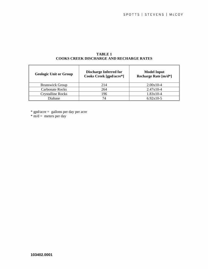
TABLE 1 COOKS CREEK DISCHARGE AND RECHARGE RATES
Geologic Unit or Group Discharge Inferred for Cooks Creek [gpd/acre*]
Model Input
Recharge Rate [m/d*]
Brunswick Group 214 2.00x10⁻⁴ Carbonate Rocks 264 2.47x10⁻⁴ Crystalline Rocks 196 1.83x10⁻⁴
Diabase 74 6.92x10⁻⁵ * gpd/acre = gallons per day per acre * m/d = meters per day
103402.0001

TABLE 2 VOLUMETRIC WATER FLOW BUDGET
Feature INFLOW (gallons per day)
OUTFLOW
(gallons per day)
Wells 0 62,000 Seeps, Springs, Drains 0 2,694,000 Streams 1,990,000 3,540,000 Recharge 4,306,000 0
TOTAL 6,296,000 6,296,000
103402.0001

TABLE 3 LAND USES AND THEIR RELATIVE RISK TO GROUNDWATER
LOW RISK 1. Land surrounding a well or reservoir, owned by a
municipality. 2. Permanent open space dedicated to passive recreation. 3. Federal, state, municipal, private parks and forests. 4. Woodlands managed for forest products. 5. Permanent open space dedicated to active recreation. 6. Field crops: Pasture, hay, grains, vegetables. 7. Low-density residential land: Lots larger than 2 acres. 8. Churches, municipal offices.
MEDIUM RISK 1. Agricultural production: Dairy, livestock, poultry, nurseries, orchards, berries.
2. Golf course, quarries. 3. Medium-density residential land: Lots from 1/2 to 1 acres. 4. Institutional uses: schools, hospitals, nursing homes, prisons,
garages, salt storage, permits, sewage treatment facilities. 5. High-density housing: Lots smaller than 1/2 acre. 6. Commercial uses: Limited hazardous material storage.
HIGH RISK 1. Retail commercial: Gasoline, farm equipment, automotive, sales and service, dry cleaners, photo processors, medical arts, furniture strippers, machine shops, radiator repair, printers, fuel oil distributors.
2. Industrial: All forms of manufacturing and processing, research facilities.
3. Underground storage of chemicals, petroleum. 4. Waste disposal: Pits, ponds, lagoons, injection wells used for
waste disposal, sanitary septic systems, bulky waste and domestic garbage landfills, hazardous waste treatment, storage and disposal sites.
5. Transportation corridor.
103402.0001
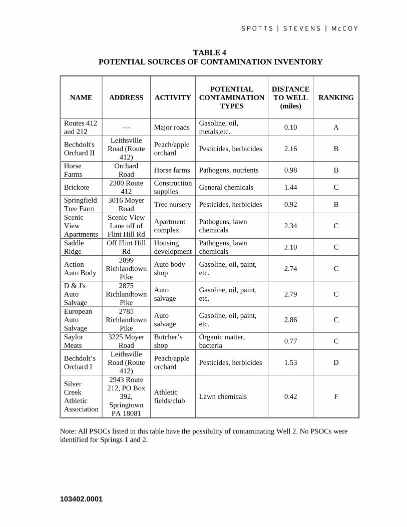
TABLE 4 POTENTIAL SOURCES OF CONTAMINATION INVENTORY
NAME ADDRESS ACTIVITY POTENTIAL
CONTAMINATION TYPES
DISTANCE TO WELL
(miles)
RANKING
Routes 412 and 212 --- Major roads Gasoline, oil,
metals,etc. 0.10 A
Bechdolt's Orchard II
Leithsville Road (Route
412)
Peach/apple orchard Pesticides, herbicides 2.16 B
Horse Farms
Orchard Road Horse farms Pathogens, nutrients 0.98 B
Brickote 2300 Route 412
Construction supplies General chemicals 1.44 C
Springfield Tree Farm
3016 Moyer Road Tree nursery Pesticides, herbicides 0.92 B
Scenic View Apartments
Scenic View Lane off of
Flint Hill Rd
Apartment complex
Pathogens, lawn chemicals 2.34 C
Saddle Ridge
Off Flint Hill Rd
Housing development
Pathogens, lawn chemicals 2.10 C
Action Auto Body
2899 Richlandtown
Pike
Auto body shop
Gasoline, oil, paint, etc. 2.74 C
D & J's Auto Salvage
2875 Richlandtown
Pike
Auto salvage
Gasoline, oil, paint, etc. 2.79 C
European Auto Salvage
2785 Richlandtown
Pike
Auto salvage
Gasoline, oil, paint, etc. 2.86 C
Saylor Meats
3225 Moyer Road
Butcher’s shop
Organic matter, bacteria 0.77 C
Bechdolt’s Orchard I
Leithsville Road (Route
412)
Peach/apple orchard Pesticides, herbicides 1.53 D
Silver Creek Athletic Association
2943 Route 212, PO Box
392, Springtown PA 18081
Athletic fields/club Lawn chemicals 0.42 F
Note: All PSOCs listed in this table have the possibility of contaminating Well 2. No PSOCs were identified for Springs 1 and 2.
103402.0001

TABLE 5 SCHEDULE AND COST OF MANAGEMENT ACTIVITIES
Management Options Identified Threat Cost Schedule for Implementation
Update ordinances General PSOCs Low 2006
Public well/spring properties easements or purchase General PSOCs High 2006
Septic system management Septic system failures Medium 2011
Community education General PSOCs Medium 2006
Emergency response plan Traffic corridors Low annually
Alternate deicing plan Traffic corridors Low 2006
Nutrient nonpoint source evaluation Nutrients Medium 2011
Notes: (1) the cost for each option has been generalized into “Low”, “Medium”, or “High” based on
the expected level of effort and likely cost to complete each management option. (2) The schedule for implementation is given as 2006 – to be done in the near future, or 2011 – to be done in the next five
years.
103402.0001
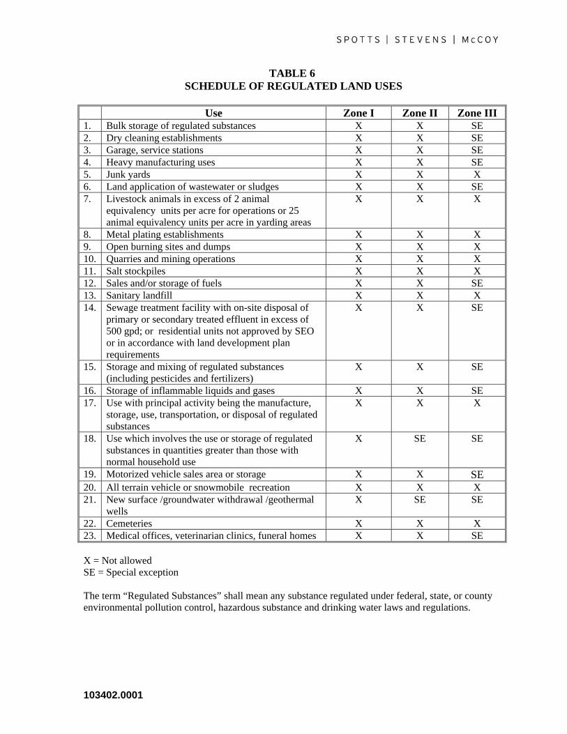
TABLE 6 SCHEDULE OF REGULATED LAND USES
Use Zone I Zone II Zone III 1. Bulk storage of regulated substances X X SE 2. Dry cleaning establishments X X SE 3. Garage, service stations X X SE 4. Heavy manufacturing uses X X SE 5. Junk yards X X X 6. Land application of wastewater or sludges X X SE 7. Livestock animals in excess of 2 animal
equivalency units per acre for operations or 25 animal equivalency units per acre in yarding areas
X X X
8. Metal plating establishments X X X 9. Open burning sites and dumps X X X 10. Quarries and mining operations X X X 11. Salt stockpiles X X X 12. Sales and/or storage of fuels X X SE 13. Sanitary landfill X X X 14. Sewage treatment facility with on-site disposal of
primary or secondary treated effluent in excess of 500 gpd; or residential units not approved by SEO or in accordance with land development plan requirements
X X SE
15. Storage and mixing of regulated substances (including pesticides and fertilizers)
X X SE
16. Storage of inflammable liquids and gases X X SE 17. Use with principal activity being the manufacture,
storage, use, transportation, or disposal of regulated substances
X X X
18. Use which involves the use or storage of regulated substances in quantities greater than those with normal household use
X SE SE
19. Motorized vehicle sales area or storage X X SE 20. All terrain vehicle or snowmobile recreation X X X 21. New surface /groundwater withdrawal /geothermal
wells X SE SE
22. Cemeteries X X X 23. Medical offices, veterinarian clinics, funeral homes X X SE X = Not allowed SE = Special exception The term “Regulated Substances” shall mean any substance regulated under federal, state, or county environmental pollution control, hazardous substance and drinking water laws and regulations.
103402.0001

Figures
Figure 1 - Location Map Figure 2 - Hydrogeologic Flow Model Figure 3 - Digital Elevation Model Figure 4 - Geologic Map Figure 5 - Hydraulic Conductivity Map Figure 6 - Potentiometric Surface Map Figure 7 - Hydrogeologic Flow Model – Computed vs. Observed Head Values Figure 8 - Source Water Protection Area Delineation Map Figure 9 - Groundwater Flow Direction Map Figure 10 - Potential Sources of Contamination Figure 11 - New Source Area Map
103402.0001
Appendix A
Hydrogeologic Model and Data Package
103402.0001

Appendix B
Zone I and Zone II Properties
103402.0001

Appendix C
Model Wellhead Protection Ordinance
103402.0001

MODEL WELLHEAD PROTECTION ORDINANCE INCLUDED AS AN EXAMPLE ONLY 1. The following uses are prohibited within wellhead protection areas (within 400 feet of a public water well): a. Bulk Storage of regulated substances b. Dry Cleaning Establishments; Coin or Commercial Laundries c. Garage, Service Station d. Heavy Manufacturing Uses
e. Junk Yards f. Land Application of Wastewater and Sludges g. Livestock Animals in Excess of 25 Animal Equivalent Units per Acre in Yarding Areas h. Medical Offices, Veterinarian Clinics, and Funeral Homes i. Metal Plating Establishments j. Open Burning Sites and Dumps k. Quarries and Mining Operations 1. Road Salt Stockpiles m. Sales, Storage, or Disposal of Fuels or Hazardous Chemicals n. Sanitary Landfill o. Sewage Treatment Facilities With On-site Disposal of Primary or Secondary
Treated Effluent in Excess of 5,000 gpd p. Storage and Mixing of Pesticides and Fertilizers q. Storage of Inflammable Liquids and Gases r. Use which involves as a principal activity the manufacture, storage, use,
103402.0001

transportation or disposal of toxic or regulated substances s. Use which involves toxic and regulated substances in quantities greater than those associated with normal household use t. Used Motor Vehicle Sales Area 2. Regulated Substance Limitations
a. The use, storage, manufacture, or disposal of Regulated Substances found on the following Regulated Substances List is prohibited within Wellhead Protection Areas except as provided under the General Exceptions provision of this Section:
REGULATED SUBSTANCES LIST
Acid and Basic Cleaning Solutions Antifreeze and Coolants Arsenic and Arsenic Compounds Bleaches, Peroxides Brake and Transmission Fluids Brine Solution Casting and Foundry Chemicals Caulking Agents and SealantsCleaning Solvents Corrosion and Rust Prevention Solutions Cutting Fluids Degreasing Solvents Disinfectants Electroplating Solutions Explosives Fire Extinguishing Chemicals Food Processing Wastes Formaldehyde Fuels and Additives Gasolines Glues, Adhesives, and Resins Greases Hydraulic Fluid Industrial and Commercial Janitorial Supplies Industrial Sludges and Stillbottoms Inks, Printing and Photocopying Chemicals Laboratory Chemicals Liquid Storage Batteries
103402.0001

Medical, Pharmaceutical, Dental, Veterinary, and Hospital Solutions Mercury and Mercury Compounds Metals Finishing Solutions Oils Paints, Primers, Thinners, Dyes, Stains, Wood Preservatives, Varnishing and Cleaning Compounds Painting Solvents PCB's Pesticides, Herbicides, Fungicides, and Rodenticides Plastic Resins, Plasticizers, and Catalysts Photo Development Chemicals Poisons Polishes Pool Chemicals in Concentrated FormProcessed Dust and Particulates Radioactive Sources Reagents and Standards Refrigerants Road Salts Roofing Chemicals and Sealers Sanitizers, Disinfectants, Bactericides, and Algaecides Soaps, Detergents, and Surfactants Solders and Fluxes Stripping Compounds Tanning Industry Chemicals Transformer and Capacitor Oils/Fluids Water and Wastewater Treatment Chemicals
3. General Exceptions
a. Many operation and maintenance activities require the use, storage, and transport
of Regulated Substances in quantities or in a manner that do not pose a significant threat to water quality. The following General Exceptions specify those activities that are permitted by right and do not require a Special Exception or Variance.
(1) Exceptions for Transit. The transportation of any regulated substance
through the Wellhead Protection Area shall be exempt from the provisions of this regulation provided the transporting motor vehicle is in transit.
(2) Exceptions for Application of Pesticides, Herbicides, Fertilizers,
103402.0001

Fungicides, and Rodenticides. The application of those Regulated Substances used as pesticides, herbicides, fertilizers, fungicides, and rodenticides in recreation, agriculture, pest control, and aquatic weed control activities shall be exempt from the provisions of this regulation provided that:
103402.0001

(a) The application is in strict conformity with the use requirement as
set forth in the substances EPA registries and as indicated on the containers in which the substances are sold.
(b) The application of any of the pesticides, herbicides, fertilizers, fungicides, and rodenticides shall be noted in the records of the certified operator. Records shall be kept of the date and amount of
these substances applied at each location and said records shall be available for inspection.
(c) The application of pesticides, herbicides, fertilizers, fungicides, and rodenticides for non-residential or non-agricultural purposes shall require a special permit.
(3) Exemption for Retail/Wholesale Sales Activities. Retail/wholesale sales
establishments that store or handle Regulated Substances for resale in their original unopened containers shall be exempt from the provisions of this regulation.
(4) Exceptions for Office and Commercial Uses. Office and commercial use
of Regulated Substances below the aggregate sum per month not exceeding twenty-five (25) gallons where said substance is a liquid or two hundred twenty (220) pounds where said substance is a solid shall be exempt from the provisions of this regulation, provided however, that office and commercial uses that store or handle quantities of Regulated Substances exceeding on a monthly basis twenty-five (25) gallons liquid or two hundred twenty (220) pounds solid shall be prohibited without receipt of a Special Exception.
(5) Exception for Construction Activities. The activities of constructing,
repairing, or maintaining any facility or improvement on lands within Wellhead Protection Areas shall be exempt from the provisions of this regulation provided that all contractors, subcontractors, laborers, material men, and their employees when using, handling, storing, or producing Regulated Substances in the Wellhead Protection Areas use those
103402.0001
applicable Best Management Practices. (6) Exception for Household Use. In addition to the exemptions provided for
in Section 3.a.(2)., the household use of Regulated Substances below the monthly aggregate sum not exceeding twenty-five (25) gallons where said substance is a liquid or two hundred twenty (220) pounds where said substance is a solid shall be exempt from the provisions of this regulation provided, however, that household uses that store or handle quantities of Regulated Substances exceeding twenty-five (25) gallons liquid or two hundred twenty (220) pounds solid shall be prohibited without receipt of a Special Exception.
(7) Exception for Municipal Use. In addition to the exemptions provided for in Section 3.a.(4)., the municipal use of Regulated Substances in quantities
used monthly exceeding twenty-five (25) gallons liquid or two hundred twenty (220) pounds solid shall be prohibited without receipt of a Special Exception.
(8) Exception for Underground Storage of Oil(s). The underground storage
of oil(s) used for heating fuel shall be exempt from the provisions of this regulation provided, however, that the container used for said storage shall be located within an enclosed structure (i.e., secondary containment or any currently approvable containment technology) sufficient to preclude leakage of oil to the external environment and to afford routine access for visual inspection (e.g., cement floored basement), and sheltered to prevent the intrusion of precipitation. Any container used for the underground storage of oil that is out of service for more than one year shall be removed. Any liquid residue shall be removed and all connecting line or pipes securely capped or plugged.
103402.0001
(9) Exception for Aboveground Storage of Oil(s). The aboveground storage of
oil(s) used for heating fuel shall be exempt from the provisions of this regulation provided, however, that the container used for said storage shall be located over an impervious pad or container sufficient to capture spills and leakage of oil to the external environment and to afford routine access for visual inspection and sheltered to prevent the intrusion of precipitation. Aboveground storage of oils shall be located as far away from the public water supply wells as possible.
4. Variance for Existing Land Uses, Facilities, and/or Activities
a. Any of the land uses, facilities, and/or activities identified in Subsection 1, lawfully in existence within the Wellhead Protection Area prior to the effective date of this ordinance, may continue to exist on the parcel upon which it is located subject to meeting existing federal, state, and local regulations including the requirements described in Subsections 5 and 6.
b. Variances to the provisions of this ordinance may be granted for undue hardships
caused to existing property owners in the Wellhead Protection Area. 5. Design Standards
a. Industrial, Commercial, and Manufacturing Facilities
(1) The following design standards apply to industrial, commercial, and manufacturing facilities which operate within the Wellhead Protection Area:
(a) Facilities which store, process, convey, and/or contain Regulated
Substances shall be designed in such a manner to prevent discharges of Regulated Substances to the environment and meet applicable regulatory requirements (i.e., Occupational Safety and
103402.0001
Health Agency (OSHA) standards, Building and Fire Codes, National Institute of Occupational Safety and Health (NIOSH) standards, EPA and PADEP requirements, etc.)
(b) Regulated Substances storage areas shall be designed with
containment structures capable of containing 100 percent of the volume of the largest storage container.
(c) No on-site floor drains shall be permitted. (d) Outside storage of Regulated Substances in drums shall not be
permitted unless stored on containment structures capable of containing 100 percent of the volume of the largest storage container.
b. Underground Storage Tanks
(1) The following design standards apply to underground storage tanks which
operate within the Wellhead Protection District:
(a) The design and construction of underground storage facilities shall
be in accordance with applicable federal and state requirements including the rules and regulations of PADEP.
(b) The tank shall be constructed of fiberglass-reinforced plastic,
coated and cathodically protected steel, or fiberglass-reinforced plastic composite.
(c) The tank and associated tank piping shall provide for secondary
containment for release detection purposes which may include double-walled tanks and piping, a concrete vault in which the tank
and piping is placed, or an impermeable liner in the excavation zone in which the tank and piping is placed.
(d) The tank shall be equipped with spill and overfill prevention
equipment and a leak detection system. c. Aboveground Storage, Tanks.
(1) The following design standards apply to aboveground storage tanks which
operate within the Wellhead Protection Area:
103402.0001

(a) The design and construction of aboveground storage tank shall be
in accordance with applicable federal and state regulations.
(b) Aboveground storage tanks shall be provided containment facilities meeting the following design requirements:
(i) The containment device shall be large enough to
contain 100 percent of the volume of the tank, in cases where a single tank is used to store, handle, use, or produce a hazardous material. In cases where multiple tanks are used, the containment device shall be large enough to contain 100 percent of the volume of the largest tank.
(ii) All containment devices shall be constructed of materials of
sufficient thickness, density, and composition to prevent structural weakening of the containment device as a result of contact with any hazardous material and shall be capable of containing any accidental release for at least a period sufficient to allow detection and removal of the material. Provisions shall be made for monitoring, testing, and immediate removal of accumulated precipitation.
(c) The design of the tank shall meet applicable technical standards for
the specific type and class of tank as set forth in the applicable Underwriters Laboratory Standards No. 142 by the American Petroleum Institute (API), by the American Water Works Association (AWWA), or by the Society of Mechanical
Engineers (ASME). The tanks shall be fabricated, tested, and installed in accordance with the appropriate codes and standards applicable to the material to be stored therein.
(d) The tank shall be designed with monitoring standards consistent
with the manufacturer's specifications.
103402.0001

(e) The tank shall be tested as required by federal and state codes and
standards.
(f) The tank and containment area shall be protected by a security fence.
d. Agricultural Operations
(1) The following design standards apply to agricultural operations within the
Wellhead Protection Area:
(a) The yarding of livestock animals, including horses, shall not exceed a density of 25 animal units per acre, within the area yarded without a Special Exception.
(b) All livestock animals shall be kept at least 50 feet from public
water supply wells. (c) Manure and pesticide storage areas shall be designed in a
manner to contain any accidental releases and provide optimal protection of the groundwater resources.
e. On-Lot Wastewater Disposal Facilities.
(1) The following design standards apply to on-lot wastewater disposal facilities within the Wellhead Protection Area:
(a) Residential and non-residential septic systems must meet all
applicable State, County, and local codes and Regulations and must be designed and operated to not cause the average concentration of nitrate-nitrogen in groundwater recharged on the property to exceed ten (10) milligrams per liter.
(b) All new septic systems must maintain a setback distance as far as
possible from public water supply wells. f. Stormwater Management Facilities
103402.0001

(1) The following design standards apply to stormwater management facilities
within the Wellhead Protection Area:
(a) Stormwater management facilities including drainage swales, detention ponds, and retention ponds shall be designed in a manner to provide optimal protection of the groundwater resources consistent with applicable PADEP requirements and guidelines.
g. Well Drilling
(1) The following design standards apply to well drilling in the Wellhead Protection Area:
(a) The drilling of public and individual water supply wells and
irrigation wells shall meet the requirements of PADEP.
(b) The Municipality shall determine the acceptability of the proposed
well location with regard to all identifiable sources of contamination, topography, surface drainage, and groundwater
conditions. h. Sinkholes
(1) The following design standards apply to sinkholes in the Wellhead Protection Area:
(a) It shall be the responsibility of the properly owner to repair sinkholes in a manner which will prevent the direct inflow of surface water into the groundwater. This will require the filling of the sinkhole with concrete, stone, or other appropriate fill.
6. Operating Requirements
a. Industrial, Commercial, and Manufacturing Facilities
(1) The following operating requirements apply to Industrial, Commercial, and Manufacturing Land Uses which operate within the Wellhead Protection Area:
(a) Owners of facilities shall apply to the Zoning Officer for a
Wellhead Protection Area Operating Permit within one-hundred
103402.0001

and eighty (180) days from the effective date of this Ordinance or before starting operation of a new facility. All Permits shall be
renewed annually thereafter. The Permit Application shall contain:
(i) A list of all Regulated Substances, including their quantities, which are stored, handled, used, or produced at the facility being permitted. This information should be consistent with public disclosure and reporting requirements in the Superfund Amendments and Reauthorization Act of 1986 (SARA) Title III. (ii) A detailed description of the activities conducted at the facility that involve the storage, handling, use, and/or production of Regulated Substances. Included with this information shall be a description of the containment structures for hazardous material storage. (iii) A detailed description of disposal procedures for Regulated Substances and wastes and name, address, and telephone number of any waste haulers used.
(iv) A site map showing the location of the facility and its property boundaries and the locations where hazardous substances are stored, handled, used, and produced.
(v) A contingency and emergency response plan which
includes procedures to be followed to prevent, control, collect, and dispose of any accidental spill or unauthorized release of a hazardous material.
(vi) An environmental audit identifying areas of
non-compliance with existing federal, state, and local regulations concerning groundwater protection. A discussion of the plans to address areas of non-compliance must be included as part of the audit.
(vii) Prepare Best Management Practices (BMPs) and
procedures for the daily in-house inspection and maintenance of areas where Regulated Substances are stored, handled, used, and/or produced. Such procedures shall be in writing and a log shall be kept of
103402.0001

all inspection and maintenance activities. Such logs shall be available for inspection by the Zoning Officer.
(viii) A detailed description of how the facility plans to
comply with federal, state, and local stormwater regulations.
(ix) Provide a detailed description of how the facility plans
to comply with the above Design Standards. b. Underground Storage Tanks
(1) The following operating requirements apply to underground storage tanks
which operate in the Wellhead Protection Area:
(a) Owners of underground storage tanks shall apply to the Zoning Officer for a Wellhead Protection Area Operating Permit within one-hundred and eighty (180) days from the effective date of this Ordinance or before starting operation of a new tank. All Permits shall be renewed annually thereafter. The Permit Application shall contain:
(i) Description of the tank including age, size, and location at
the facility.
(ii) Description of the type and quantity of material stored in
the tank.
(iii) Documentation that the tank is in compliance with existing federal, state, and local regulations including any leak tests performed on the tank.
(iv) Documentation that the tank is properly registered as
required by federal and state regulations.
(b) Leak detection systems shall be checked for evidence of a release
at least every 30 days.
103402.0001

(c) Existing tanks shall be upgraded as required to meet applicable federal and state regulations.
(d) Owners shall meet federal and state requirements for release
detection recordkeeping, reporting, and notification.
(e) Provide a detailed description of how the Owners plan to comply
with the above Design Standards. c. Aboveground Storage, Tanks
(1) The following operating requirements apply to aboveground storage tanks
which operate within the Wellhead Protection Area:
(a) Owners of aboveground storage tanks shall apply to the Zoning Officer for a Wellhead Protection Area Operating Permit within one-hundred and eighty (180) days from the effective date of this Ordinance or before starting operation of a new tank. All Permits shall be renewed annually thereafter. The Permit Application shall contain:
(i) Description of the tank including age, size, and location at
the facility.
(ii) Description of the type and quantity of material stored in
the tank.
(iii) Documentation that the tank is in compliance with existing federal, state, and local regulations.
(iv) Copy of Spill Prevention Response Plan consistent with
applicable Federal and State regulations and requirements.
(b) Existing tanks shall be upgraded as required to meet applicable
federal and state regulations.
(c) Owners shall meet federal and state requirements for release
103402.0001

detection recordkeeping, reporting, and notification. (d) Provide a detailed description of how the Owners plan to
comply with the above Design Standards. d. Agricultural Operations (1) The following operating requirements apply to agricultural lands
which operate within the Wellhead Protection Area: (a) Owners of lands utilized for agricultural production shall apply
to the Zoning Officer for a Wellhead Protection Area Operating Permit within one-hundred and eighty (180) days from the effective date of this Ordinance or before starting agricultural production of new lands. All Permits shall be renewed annually thereafter. The Permit Application shall contain:
(i) The amount of total tillable acres, type of crops, and
number and type of livestock raised on the farm. (ii) Nutrient/Manure Management Program in accordance with Federal, State, and local guidelines and requirements. (iii) Soil Conservation Plan prepared by the Soil
Conservation Service. (iv) The amount and types of pesticides and fertilizers
stored on the farm.
(b) Agricultural operations shall utilize integrated pest management techniques to minimize the risk to groundwater systems associated with the application of pesticides and herbicides.
(c) Detailed descriptions of how the Owners plan to comply with
the above Design Standards.
103402.0001

Appendix D
Public Education Brochure
103402.0001


![[EMC] Source Code Protection](https://static.documents.pub/doc/80x56/5598684b1a28ab9a738b4622/emc-source-code-protection-559c124acb5e2.jpg)
