This manual has been written and illustrated to present the basic installation, operation and servicing instructions of the Sprite III Warewash Dispensing System. Guidelines will be suggested in reference to the preferred method of installation, however, the variety of equipment and the surrounding environment will dictate the actual installation of the Sprite III.
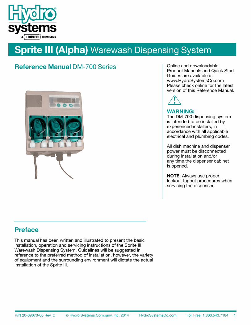
Sprite III (Alpha) Warewash Dispensing System
Online and downloadable Product Manuals and Quick Start Guides are available at www.HydroSystemsCo.com Please check online for the latest version of this Reference Manual.
!WARNING:The DM-700 dispensing system is intended to be installed by experienced installers, inaccordance with all applicable electrical and plumbing codes.
All dish machine and dispenser power must be disconnected during installation and/orany time the dispenser cabinet is opened.
NOTE: Always use proper lockout tagout procedures when servicing the dispenser.
8 Maintenance and Service Overview ........................................................................................................................................26 Routine Maintenance .....................................................................................................................26 Every Maintenance Visit .................................................................................................................26 Pump Tube Replacement ...............................................................................................................26 Spare Parts Reference ...................................................................................................................27 9 Specifications and Warranty Specifications.................................................................................................................................29 Limited Warranty ............................................................................................................................29 Limitation of Liability ......................................................................................................................29 Index
Advanced DesignThe Sprite III uses miniaturized electronics to provide powerful features in a small package. A digitalreadout allows simple three-key programming of all options.
ReliabilityThe gasket-enclosed Sprite III Warewash Dispenser is highly water resistant. The readout gives confirmation of detergent, rinse and third product feed.
VersatilityThe Sprite III can be configured as a conductivity probe controlled unit or as a probeless, time-baseddispenser. It can accept a 100 VAC nominal to 240 VAC nominal (+/- 10% fluctuation) main powerinput at 50 or 60 Hz. Rinse and Detergent control signals are universal “machine interface” typesthat are capable of accepting any voltage from 24 to 240 VAC nominal (+/- 10% fluctuation) or 24VDC (+/- 20% fluctuation). Sprite III can control either powder (solid) or liquid detergents.
Cost SavingsA special Rinse Saver feature prevents rinse additive waste during fills of the washer; digitalelectronics ensure accurate detergent control and minimize overuse.
IntelligenceThe Sprite III includes a rack counter as a “standard” feature. A unique “De-Lime” mode allows forsafe washer cleaning without detergent waste.
RobustnessA full range of programmable options are included, such as rinse delay, variable alarm volume, andmanual prime for both rinse and detergent.
Audible and Visible AlarmsIn Probe Mode, alert the operator when the detergent is running low or when the wash tank waterneeds to be changed. Customize the parameters that cause these alarms to sound and display.
Easy Service/RepairThe Sprite III features convenient front access for all servicing. No internal access to the cabinet isrequired for installation and routine maintenance. In the unlikely event that repairs are required,spare parts are available in modular form for fast and convenient service.
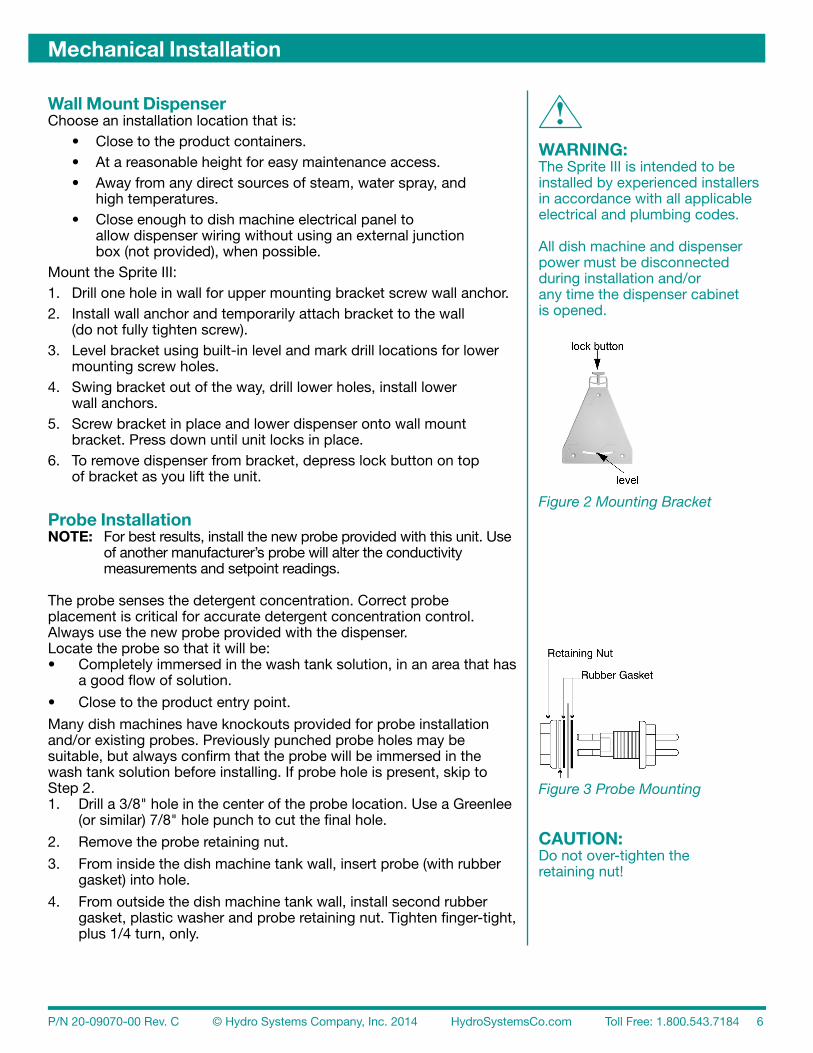
Wall Mount DispenserChoose an installation location that is: • Close to the product containers. • At a reasonable height for easy maintenance access. • Away from any direct sources of steam, water spray, and
high temperatures. • Close enough to dish machine electrical panel to
allow dispenser wiring without using an external junction box (not provided), when possible.
Mount the Sprite III:1. Drill one hole in wall for upper mounting bracket screw wall anchor.2. Install wall anchor and temporarily attach bracket to the wall
(do not fully tighten screw).3. Level bracket using built-in level and mark drill locations for lower
mounting screw holes.4. Swing bracket out of the way, drill lower holes, install lower
wall anchors.5. Screw bracket in place and lower dispenser onto wall mount
bracket. Press down until unit locks in place.6. To remove dispenser from bracket, depress lock button on top
of bracket as you lift the unit.
Probe InstallationNOTE: For best results, install the new probe provided with this unit. Use of another manufacturer’s probe will alter the conductivity measurements and setpoint readings.
The probe senses the detergent concentration. Correct probeplacement is critical for accurate detergent concentration control.Always use the new probe provided with the dispenser.Locate the probe so that it will be:• Completely immersed in the wash tank solution, in an area that has
a good flow of solution.
• Close to the product entry point.
Many dish machines have knockouts provided for probe installationand/or existing probes. Previously punched probe holes may besuitable, but always confirm that the probe will be immersed in thewash tank solution before installing. If probe hole is present, skip toStep 2.1. Drill a 3/8" hole in the center of the probe location. Use a Greenlee (or similar) 7/8" hole punch to cut the final hole.
2. Remove the probe retaining nut.
3. From inside the dish machine tank wall, insert probe (with rubber gasket) into hole.
4. From outside the dish machine tank wall, install second rubber gasket, plastic washer and probe retaining nut. Tighten finger-tight, plus 1/4 turn, only.
!WARNING:The Sprite III is intended to be installed by experienced installers in accordance with all applicable electrical and plumbing codes.
All dish machine and dispenser power must be disconnected during installation and/orany time the dispenser cabinet is opened.
Rinse Injection Fitting InstallationThe injection fitting threads into 1/8" NPT female threads. If the dishmachine rinse plumbing is thin wall pipe, use a saddle clamp with a 1/8" NPT threaded hole. If an optional pressure switch will be used,thread the injection fitting into one side of the pressure switch watersource fitting pipe tee.
Install the rinse injection fitting in a location that is:• At least 6" below the dish machine rinse plumbing vacuum breaker or solenoid valve (to conform to plumbing codes).• On continuous rack, flight, or conveyor machines: be sure this location is downstream from any rinse makeup water.
The dish machine may already have a tapped hole present toaccommodate the fitting; if this is the case, skip to Step 3.
1. Drill a 7/32" hole in the rinse plumbing injection location.2. Tap the hole drilled in Step 1 with a 1/8" NPT tap.3. Install the injection fitting. Use thread sealant to ensure
a leak-free assembly.
Detergent Bulkhead Fitting InstallationNOTE: If you are using a solid, powder, or slurry feed system, follow your system’s instructions. Use the following section for liquid detergent applications.
Correct detergent bulkhead fitting placement is critical for accuratedetergent concentration control (probe mode only). Choose a mountinglocation for the detergent bulkhead fitting that is:• Above the water line in the tank• Close to the probe location (when possible).• Discharging detergent directly into the wash tank and not on top of any shelf areas or other obstacles that could prevent detergent from falling directly into the wash tank.
Previously punched holes may be suitable, but always confirm that the fitting is above the water line before installing.
If a hole is present, skip to Step 2.
1. Drill a 3/8" hole in the center of the detergent inlet location. Use a Greenlee (or similar) 7/8" hole punch to cut the final hole. Remove the detergent bulkhead fitting retaining nut.
2. From inside the dish machine, insert detergent bulkhead fitting (with rubber gasket) into hole.
3. From outside the machine, install second rubber gasket, plastic washer, and plastic retaining nut. Tighten finger-tight, plus 1/4 turn, only.
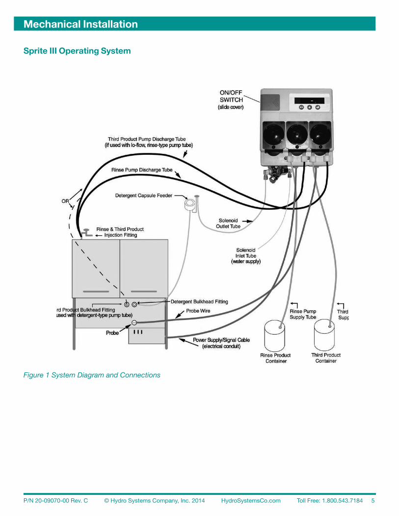
Rinse / Detergent Supply and Discharge Tube InstallationNOTE: Supply and discharge tubing is only included with the super kits.
1. Route pump supply tubes from supply containers to the inlet sides (left) of each respective pump. Slip the tube through the compression nut into fitting and tighten.2. Route pump discharge tubes to the outlet sides (right) of each respective pump. Slip the tube through compression nut into fitting and tighten.3. Route other end of rinse pump discharge tube to rinse injection fitting. Slip the tube through compression nut into fitting and tighten.4. Route other end of detergent pump discharge tube to the detergent bulkhead fitting. Slip the tube through compression nut into fitting and tighten.
Figure 6 Sprite III Dispensing System
Solenoid Water Feed InstallationNOTE: The following instructions are for Solenoid-equipped units only.
If you are using a solid, powder, or slurry type feed system you willneed a water source for the dispenser solenoid valve. This watersupply may be hot or cold, but for safety reasons should not comefrom the boosted temperature rinse water line on high temperaturedish machines. The dispenser solenoid valve fittings are 1/4" (6 mm onmetric units) compression.
Typically, a saddle clamp is used for the solenoid valve water source. If the plumbing is steel or brass, you can drill a 7/32" hole and tap for1/8" NPT threads.
1. Install petcock valve to water source plumbing. Connect 1/4" copper or plastic tube to the valve.
2. Route tube to the dispenser solenoid valve. Slide tube into water inlet side compression fitting and tighten.
3. Connect another 1/4" tube to the outlet side of the dispenser solenoid valve and route to the water inlet connection for the feed system.
4. Confirm all compression fittings are tight.5. Be sure to turn on water source valve prior to adjusting
dispenser settings.
!CAUTION:If the water source is hot, use only copper tubing. DO NOT use poly tubing. DO NOT connect solenoid to the boosted temperature rinse water line on high temperature dish machines.
Third Product Pump Installation (Optional)The third product pump will run with either the rinse pump (as a sanitizer pump) or the detergent pump (as ade-stainer pump), depending upon the Third Product Menu setting. Refer to “Third Product Pump Selection(Menu 3rd)” on page 23 and “Third Product Prime (Menu 3 P)” on page15 for configuration information.
Third Product as a Sanitizer To use the Third Product Pump as a sanitizer with the rinse pump, use a plastic injection fitting and refer to the instructions for “Rinse Injection Fitting Installation” on page 7.
Third Product as a De-Stainer To use the Third Product Pump as a de-stainer with the detergent pump, use a 1/4" bulkhead fitting and refer to the instructions for “Detergent Bulkhead Fitting Installation” on page 7.
Disable Third Product Pump To disable the Third Product Pump, set the motor speed to zero in the Adjustment Menu for Probe Mode (see “Third Product Pump Speed (Menu 3PS)” on page 25) or Probeless Mode (see “Third Product Pump Speed (Menu 3PS)” on page 25).
Electrical Installation
IMPORTANT: All high voltage wiring must be performed with the cable provided and must be enclosed in flexible conduit, seal-tite or other housing approved for damp locations. The Sprite III dispensing system is intended to be installed by experienced installers in accordance with all applicable electrical and plumbing codes. All dish machine and dispenser power is to be disconnected during installation and/or any time the dispenser cabinet is opened. Always verify all voltage sources with a meter.
Please note the following additional electrical information:• All electrical connections (except the probe) must be in either the dish machine control circuit panel or an external junction box.• The dispenser is pre-wired with a multi-conductor electrical cable that must be run through a conduit to the hard-wired connections on the dish machine.• Use a 1/2" (13 mm) ID water tight conduit that meets all local and national codes. A conduit fitting is on the bottom of the dispenser, where the power cable exits.• The probe wire is also pre-wired and should be routed to the probe location and cut to length if a probe is used.
Probe WiringNOTE: To maintain the IP rating of the unit, watertight, flexible conduit should be used to route the probe wire. Failure to use watertight, flexible conduit will impair water resistance of the unit enclosure.
1. Route the probe wire to the probe location and cut to fit. If you need to extend the probe wire, use high quality, corrosion resistant or waterproof butt splices with a quality crimping tool.
2. Strip wire ends and crimp on the ring lugs provided.3. Connect the ring lugs to the probe with nuts and split washers provided. Be sure that connections are
Electrical ConnectionsSprite III includes two separate wiring cables: The Main Power Cable (with Input Trigger Signal ) must be routed through a conduit fitting; the conductivity probe connection cable does not require a conduit. Sprite III can be connected to single-phase power systems or to many 3-phase power systems. Instructions for each type of power system follows. Use the type that applies to the power system at your site.
Main Power Wiring – Single-Phase Power Systems Connection Instructions for Single-Phase Power Systems1. Power input to the Sprite III can be any voltage, from 100– 240VAC nominal, 50Hz or 60Hz. The neutral source is connected to the Light Blue wire of the seven-wire harness.2. The Hot source is connected to the Brown wire.3. The Green/Yellow wire must be connected to Earth/Ground.
Main Power Wiring – 3-Phase Power SystemsThe Sprite III can be connected to many common three-phase power systems, if all requirementsoutlined in “Requirements for 3-Phase Power Connections” (below) are met. After meeting theserequirements, refer to the illustrations shown in Figure 8 “Connection Diagrams for 3-Phase PowerSystems” below. Use the diagram that applies to the power system at your site.
Requirements for 3-Phase Power Connections1. The Sprite III is a single-phase load. Line voltage is applied using just two wires (Brown and Blue). A separate safety ground is required and must be connected (Green/Yellow wire).2. Avoid interconnection to power systems that are not ground-referenced.3. Where several connection options exist, choose a connection between a line (phase) and neutral. Connect the Light Blue wire to the neutral line.4. The nominal AC voltage (between Brown and Light Blue wires) MUST NOT exceed 240 volts.5. The Green/Yellow wire is for interconnection to earth ground only. Do not connect line, phase or neutral wires to the Green/Yellow wire.6. For operation from 220/380 and 240/415 power systems, a neutral connection MUST be available.
Connection Diagrams for 3-Phase Power Systems
Figure 8 Connection Diagrams for 3-Phase Power Systems
Figure 7 Single-Phase Power Wiring Diagram
1. 120/208 VAC WYE includes Neutral and Ground
2. 120/240 VAC Delta with High Leg
3. 220/380VAC or 240/415VAC WYE includes Neutral and Ground
Note:An accessible neutral isrequired. Connect betweenline and neutral ONLY.
Detergent Signal WiringThe detergent signal input is an optically isolated signal input thatdraws no more than 20 mA. It is a universal DC voltage input thataccepts any voltage between 24 and 240 VAC nominal (+/- 10%fluctuation), or 24 VDC nominal (+/- 20% fluctuation).
Detergent Signal Wiring – Probe Mode Typical wiring locations are dispenser detergent power source or the wash motor contacts in the dish machine control panel. This power source is on when the dishwasher is running the wash pump. • Connect yellow (DC +) and white/yellow (DC -) colored wires to detergent power source.
Detergent Signal Wiring – Probeless Mode On conveyor type dishwashers, the detergent signal must occur only once per dish machine fill/drain occurrence–beginning when the dish machine fills. Typical wiring locations are an “on light”. Each time this power source comes on, and stays on for ten seconds, the dispenser will feed the detergent initial charge amount (with probeless and automatic initial charge modes set).
On door-type dishwashers, connect the detergent signal input to the dispenser detergent power source or the wash motor contacts in the dish machine control panel. This power source is on when the dishwasher is running the wash pump. • Connect yellow (DC +) and white/yellow (DC -) colored wires to initial charge power source.
Rinse Signal WiringThe rinse signal input is an optically isolated signal input that draws no more than 20 mA. It is a universal DC voltage input that accepts any voltage between 24 and 240 VAC nominal (+/- 10% fluctuation), or 24 VDC nominal (+/- 20% fluctuation). Typical wiring locations are dispenser rinse power source or the rinse solenoid valve circuit in the dish machine control panel. This power source must be live whenever the dishwasher is rinsing. When no suitable rinse signal connection is available, an optional pressure switch may be used with a constant power source instead.• Connect violet (DC +) and white/violet (DC -) colored wires to rinse (or constant power for pressure switch installations) power source.
Probeless Mode
NOTE: Certain dishwasher designs require that the rinse aid be dispensed upon the detergent signal rather than the rinse signal. In this case, you must still connect the rinse signal input to either the fill solenoid or the rinse solenoid circuit of the dishwasher to enable automatic initial charge function in probeless mode.
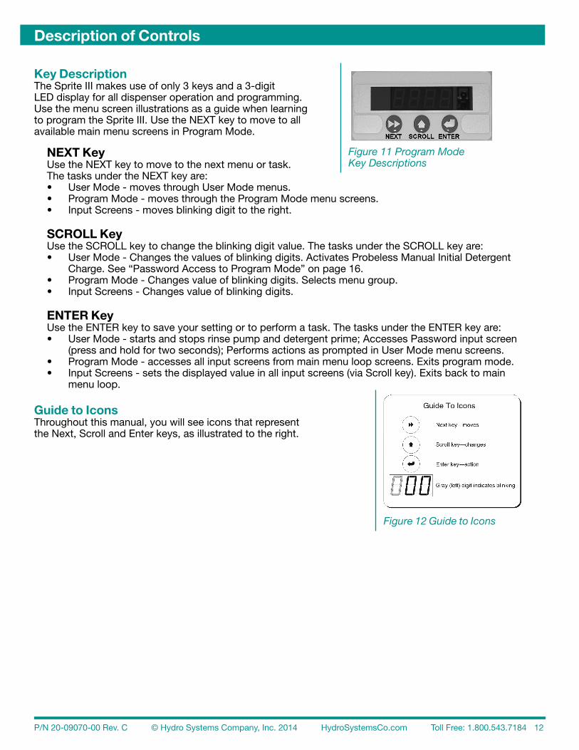
Key DescriptionThe Sprite III makes use of only 3 keys and a 3-digit LED display for all dispenser operation and programming. Use the menu screen illustrations as a guide when learning to program the Sprite III. Use the NEXT key to move to all available main menu screens in Program Mode.
NEXT KeyUse the NEXT key to move to the next menu or task. The tasks under the NEXT key are:• User Mode - moves through User Mode menus.• Program Mode - moves through the Program Mode menu screens.• Input Screens - moves blinking digit to the right.
SCROLL KeyUse the SCROLL key to change the blinking digit value. The tasks under the SCROLL key are:• User Mode - Changes the values of blinking digits. Activates Probeless Manual Initial Detergent Charge. See “Password Access to Program Mode” on page 16.• Program Mode - Changes value of blinking digits. Selects menu group.• Input Screens - Changes value of blinking digits.
ENTER KeyUse the ENTER key to save your setting or to perform a task. The tasks under the ENTER key are:• User Mode - starts and stops rinse pump and detergent prime; Accesses Password input screen (press and hold for two seconds); Performs actions as prompted in User Mode menu screens.• Program Mode - accesses all input screens from main menu loop screens. Exits program mode.• Input Screens - sets the displayed value in all input screens (via Scroll key). Exits back to main menu loop.
Guide to IconsThroughout this manual, you will see icons that represent the Next, Scroll and Enter keys, as illustrated to the right.
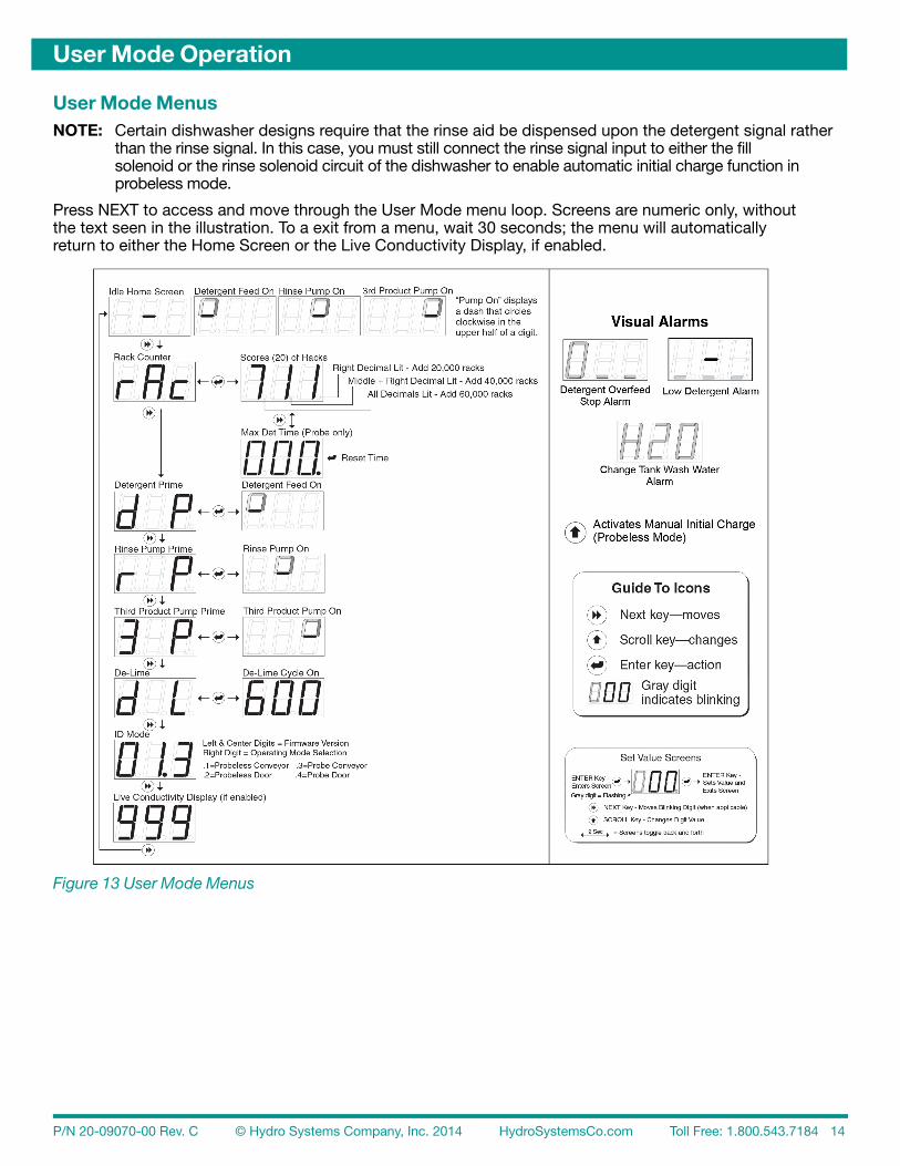
User Mode MenusNOTE: Certain dishwasher designs require that the rinse aid be dispensed upon the detergent signal rather than the rinse signal. In this case, you must still connect the rinse signal input to either the fill solenoid or the rinse solenoid circuit of the dishwasher to enable automatic initial charge function in probeless mode.
Press NEXT to access and move through the User Mode menu loop. Screens are numeric only, withoutthe text seen in the illustration. To a exit from a menu, wait 30 seconds; the menu will automaticallyreturn to either the Home Screen or the Live Conductivity Display, if enabled.
Rack Counter (Menu rAc)NOTE: On door-type dishwashers, a rack is counted each time the rinse signal is activated.
On conveyer-type dishwashers, a rack is counted based on the time set in Configuration Menu Rack Time in Rinse (rtr).The rack counter keeps track of up to 79,980 racks run before it needs to be manually reset. Racks arecounted by scores (sets of 20 racks). This means that a rack count display of 700 equals 14,000 racksrun. When the maximum number (999) displays, the right decimal is lit. This indicates that approximately20,000 racks have run and the display rolls over to 000. When 20 more racks have run, the displayshows 001. The rack count is then 20 plus 20,000 = 20,020.
When another approximately 20,000 racks have run, the rack counter reaches 999 a second time and themiddle and right decimal are lit. This indicates that approximately 40,000 racks have run and the displayrolls over to 00.0. until it reaches 999 a third time and rolls over to 0.0.0. (all decimals are lit). Thisindicates that approximately 60,000 racks have run.
When the display reaches 9.9.8. and all decimals are lit, this indicates that approximately 79, 940 rackshave run. No additional racks will be counted until the Rack Counter is reset (see “Rack Counter Reset(rCr)” on page 22.)
To view the Rack Count (rAc) and/or Maximum Detergent Time:1. Press NEXT to display the Rack Counter (rAc). Press ENTER to display racks washed.2. In Probe Mode only, press NEXT to display “Max Det Time,” the longest time the detergent feed has to run to satisfy the setpoint. Make note of this time after a new installation.3. Press NEXT to toggle back to rAc, then press ENTER to return to the main menu loop.
Detergent Prime (Menu dP)1. Press NEXT to display d P.2. Press ENTER to start detergent feed.3. Press ENTER again to stop detergent feed and return to the main menu loop. Prime automatically stops after 30 seconds.
Rinse Prime (Menu r P)1. Press NEXT to display r P.2. Press ENTER to start (or stop) the selected pump. Prime automatically stops after 30 seconds.
Third Product Prime (Menu 3 P)1. Press NEXT to display 3 P.2. Press ENTER to start (or stop) the selected pump. Prime automatically stops after 30 seconds.
De-Lime (Menu d L)1. Press NEXT to display d L.2. Press ENTER to start the De-Lime Cycle (10 minutes). During this time, all dispenser operation is stopped.3. Press ENTER to stop the De-Lime Cycle early, and return to the main menu loop.
ID Mode ScreenPress NEXT to display the ID Mode screen. Used primarily for troubleshooting, ID Mode displays theSprite III version and current operating mode. The left and center digits display the unit version.The right digit displays the current operating mode, as defined below:.1 = Probeless Conveyer .2 = Probeless Door .3 = Probe Conveyer .4 = Probe Door
Live Conductivity DisplayThe current conductivity reading is displayed, if enabled. This displays continuously and does nottime out.
Password Access to Program Mode1. Press and hold ENTER for 2 seconds to access the Password input screen. The factory-set password is 123.2. Press SCROLL to change the blinking digit to the desired value.3. Press NEXT to move the blinking digit.4. Press ENTER to set all numbers and exit to Program Mode. An incorrect password entry returns you to the home screen.
Manual Initial Charge Function (Probeless Mode ONLY)1. From the Home Screen, press SCROLL to activate manual initial charge.2. Press SCROLL again to terminate manual initial charge early.
Rinse Saver FeatureRinse Saver is always operational and does not require additional programming. Rinse Saver preventsproduct waste when filling the tank and assures that rinse will only operate under the following conditions:• The detergent signal has occurred within the previous 90 seconds.• There is a rinse input signal on the board. On door-type dishwashers, Rinse will operate as long as the rinse signal is present but not longer than 20 seconds continuously.
Display IndicatorsIn User Mode, information about the dispenser’s operation is seen in the following displays, which mayoccur in combination with each other during normal operation:• Idle Home Screen (Center Digit): Dash in center digit indicates that power is on.• Detergent Feed On (Top Half of Left Digit): One segment continuously rotates clockwise.• Rinse Pump On (Top Half of Center Digit): One segment continuously rotates clockwise.• Third Product Feed On (Top Half of Right Digit): One segment continuously rotates clockwise.• Alarms (alarms are audible ONLY IF the Alarm Volume is set to Lo, ME or H i in the ALr menu): – Low Detergent Visual Alarm (Probe Mode Only): Bottom segments flash on all three digits and an audible alarm sounds. (See “Low Detergent Alarm (Probe Mode ONLY)” on page 16). – Detergent Overfeed Stop Alarm (Probe Mode Only): Left digit displays a zero; bottom segments of center and right digits flash and an audible alarm sounds. (See “Detergent Overfeed Stop Alarm (Probe Mode ONLY)” on page 17.) – Change Wash Tank Water Alarm (All Modes): Display flashes H20 and audible alarm beeps intermittently. (See “Change Tank Wash Water Alarm (Menu CtA)” on page 17.)
Low Detergent Alarm (Probe Mode ONLY)Activation of the Low Detergent Alarm will not interrupt the operation of the dish machine.In conveyor machines, the low detergent alarm occurs only when the following conditions are met:• A detergent signal occurs, AND• The conductivity level falls below the programmed setpoint AND• The detergent concentration does not increase when the detergent feeds within a preset number of racks washed, as programmed in Low Detergent Alarm Delay (LdA) of Program Mode.
In door machines, the low detergent alarm (audible and visual) occurs only when the following conditionsare met:• Conductivity is below the programmed setpoint, AND• The number of programmed rack-count errors have been reached. (A rack-count error occurs each time there is a rinse signal that occurs within 5 minutes of the detergent signal.)Visual Alarm: Flashing lower segments of all three digitsAudible Alarm: Beeps three times per rack (ONLY IF Alarm Volume is not set to oFF in the ALr menu) Reset Low Detergent Alarm Conditions that will cause the alarm to reset are: 1. Conductivity rises by 10% (OR rises to the setpoint) within the number of racks set in “Low Detergent Alarm Delay” (LdA), OR 2. A key is pressed on the controller (pause), OR 3. Device power is cycled off and on (alarm will resume unless conductivity rises).
Detergent Overfeed Stop Alarm (Probe Mode ONLY)The detergent overfeed stop alarm occurs if a low detergent alarm condition continues for twice the presetnumber of racks washed (as programmed in the Low Detergent Alarm Delay Menu > AJ.P > LdA).At that point, the detergent feed stops and the audible and visual alarm changes to indicate the detergentoverfeed stop.
Visual Alarm: Flashing left zero and flashing center and right lower lines Audible Alarm: Sounds continually in bursts of three beeps (ONLY IF Alarm Volume is not set to oFF in the ALr menu)
To begin detergent feed after changing the product container, press any key to reset this alarm.
Change Tank Wash Water AlarmThe change tank wash water alarm alerts the operator to drain the wash tank and refill it with freshwater. The alarm occurs after the number of racks set in “Change Tank Wash Water Alarm (Menu CtA)”have run. The alarm must be enabled; the default setting is OFF.
Visual Alarm: Flashing H20 Audible Alarm: Sounds intermittent beeps in conjunction with flashing display (ONLY IF Alarm Volume is not set to oFF in the ALr menu)
To stop and reset the alarm, press any key after changing the wash water.
NOTE: Alarm racks are counted as individual racks (1-999), unlike the total Rack Count, which is counted in sets of 20 racks (20 racks equal 1 score).
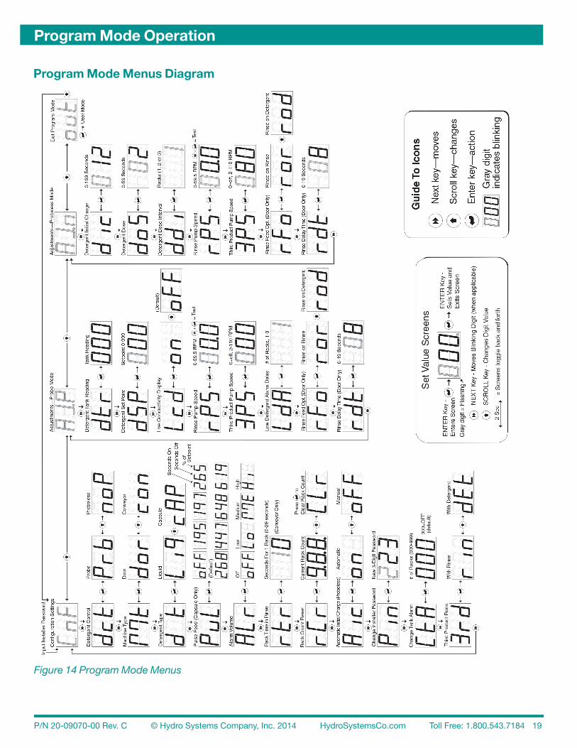
OverviewProgram Mode consists of three circular, top-level menu loops. Menus are represented by an acronym thatappears on the display. Programming selections appear as either acronyms or as numbers. Menus anddefault settings are illustrated in Figure 14 “Program Mode Menus” on page 19.
The Configuration Settings loop (CnF) is always available. There are two Adjustment Menu loops: Probe(AJ.P) or Probeless (AJ.n). To simplify programming, only one Adjustment Menu is accessible, as determinedby Detergent Control (dct) selection of Probe or Probeless in the Configuration Setting.
NOTE: Alarm racks are counted as individual racks (1-999), unlike the total Rack Count, which is counted in sets of 20 racks (20 racks equal 1 score).
IMPORTANT: When programming the dispenser for a new installation, always set the Configuration Settings first.
After the Configuration has been set, program the dispenser adjustments (either Probe or Probeless) in the available Adjustment Menu loop. Subsequent maintenance adjustments will typically be made in the same Adjustment Menu loop.
Password Access to Program ModeYou must input the correct password to enter Program Mode. Use the factory-default setting, as described below, or customize the password, as described in “Edit Installer Password (Menu Pin)” on page 22.
1. Input Installer Password as described in “Password Access to Program Mode” on page 16 or see “Configuration Settings (Menu CnF)” on page 20 for a graphic illustration of password input.2. Press SCROLL to change the blinking menu from CnF (Configuration Settings), to AJ.P (Adjustments—Probe) or AJ.n (Adjustments—Probeless), or to out to exit Program Mode.3. Press NEXT to move between the top-level main menu loops CnF, AJ.P and AJ.n.4. Press ENTER to exit Program Mode when out (Exit Program Mode) displays. Program Mode is automatically exited after 5 minutes of inactivity.
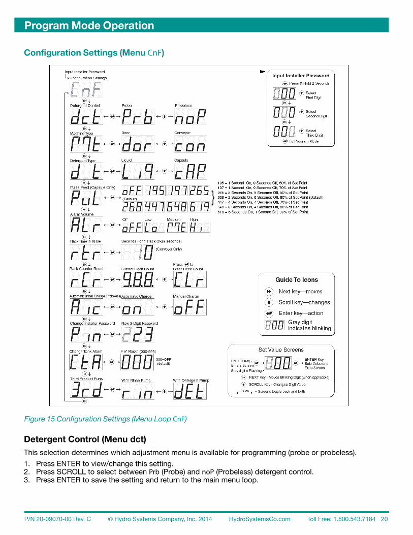
Detergent Control (Menu dct)This selection determines which adjustment menu is available for programming (probe or probeless).
1. Press ENTER to view/change this setting.2. Press SCROLL to select between Prb (Probe) and noP (Probeless) detergent control.3. Press ENTER to save the setting and return to the main menu loop.
Machine Type (Menu Mt)1. Press ENTER to view/change this setting.2. Press SCROLL to select between dor (Door) and con (Conveyor) machine type.3. Press ENTER to save the setting and return to the main menu loop.
Detergent Type (Menu d t)1. Press ENTER to view/change this setting.2. Press SCROLL to select either Select LiP (liquid) or cAP (capsule) detergent type. Pulse feed times for liquid detergent are fixed at 3 seconds on / 3 seconds off at 80-100% of setpoint. Pulse feed times for capsule detergent are set in the next menu.3. Press ENTER to save the setting and return to the main menu loop.
Pulse Feed – Capsule Detergent in Probe Mode ONLY (Menu PuL)NOTE: This menu displays only if menu dct (Detergent Control) is set to prb (Probe)
1. Press ENTER to view/change this setting.2. Press SCROLL to change the value, then press ENTER to save the setting and return to the Configuration Settings Menu loop. The settings are as follows: 195 = 1 Second on, 9 Seconds off, 50% of setpoint 197 = 1 Second on, 9 Seconds off, 70% of setpoint 265 = 2 Seconds on, 6 Seconds off, 50% of setpoint 268 = 2 Seconds on, 6 Seconds off, 80% of setpoint (Default) 447 = 4 Seconds on, 4 Seconds off, 70% of setpoint 648 = 6 Seconds on, 4 Seconds off, 80% of setpoint 619 = 6 Seconds on, 1 Second off, 90% of setpoint oFF = No pulse feed
Alarm Volume (Menu ALr)1. Press ENTER to view/change this setting.2. Press SCROLL to select between oFF (Off), Lo (Low), ME (Medium), or Hi (High) alarm volume. A half-second beep will sound for each level as the SCROLL key is pressed.3. Press ENTER to save the setting and return to the main menu loop.
Rack Time in Rinse – Conveyor Machines ONLY (Menu rtr)NOTE: Rack Time in rinse applies only to conveyor type dishwashers. It is used to count racks and to determine detergent dose intervals when in Probeless Mode.
To determine the number of seconds to input in this screen, time (and make note of) the number of seconds the dish machine conveyor takes to move one rack a single rack length’s distance.1. Press ENTER to view/change this setting. The range is 0-29 seconds. The default is 10 seconds.2. Press SCROLL to change the value of the blinking center digit (tens), then press NEXT to move to the right digit (ones), which begins blinking.3. Press SCROLL to change the value of the blinking right digit.4. Press ENTER to save the setting and return to the main menu loop.
Rack Counter Reset ( rCr)The Rack Counter counts racks by scores (sets of 20 racks). Every 20,000 racks, a decimal lights up, the rackcounter rolls from 999 to zero and begins counting the next 20,000 racks. The maximum of 80,000 racks displays as 999 and all decimals lit. No additional racks are counted until the rack count is reset to zero.
1. With rCr displayed, press ENTER to view the current rack count.2. With the current rack count displayed, press SCROLL to change the display to CLr (Clear).3. With CLr displayed, press ENTER to clear the rack count. 000 displays as the new rack count. (To exit without clearing the rack count, press SCROLL to return to the current rack count.)4. Press ENTER to return to the main menu loop.
Automatic Initial Charge - Probeless Only (Menu A ic)NOTE: This setting only applies to probeless detergent control when selected in menu dct. It determines whether the Initial Charge is Automatic (on) or Manual (oFF).
In Manual Initial Charge (A ic is oFF), the user presses SCROLL to start an Initial Charge.
An Automatic Initial Charge in a door-type dishwasher (A ic is on), occurs each time the dispenserreceives a rinse signal that was not preceded by a detergent signal within the prior 90 seconds (i.e. on aninitial fill). Then, after a 1 second signal qualification, the dispenser detects an Automatic Initial Chargeand disabling the rinse feed and feeding detergent for the time set in menu dic (Detergent InitialCharge). Normal rinse signal activations (within 90 seconds after a detergent signal) do not generate aninitial charge. A five minute lockout timer begins at the start of the initial charge; this prevents an additionalinitial charge from occurring if multiple rinse signals are detected during fill.
An Automatic Initial Charge in a conveyor-type dishwasher (A ic is on), occurs each time the dispenserdetects a detergent signal input (three second filter) that remains on for 10 seconds continuously.Then, the rinse pump turns off for 90 seconds (or Detergent Initial Charge time, if longer), and the detergentfeeds for the time set in “Detergent Initial Charge (Menu dic)” on page 27.This will happen each time a detergent signal occurs, so the source of this signal must remain on forentire time the tank is full, or must not occur more than once per machine fill. (See Chapter 2 “ElectricalInstallation” for more information.)
To enable or disable the Automatic Initial Charge:1. Press ENTER to view/change this setting.2. Press SCROLL to select between on (Automatic) and oFF (Manual) initial detergent charge.3. Press ENTER to save the setting and return to the main menu loop.
Edit Installer Password (Menu P in)CAUTION: Be sure to note the new password if you change it from the factory setting (123). If your password is lost, contact Technical Support.
1. Press ENTER to change to change the password to any three-digit number.2. Press SCROLL to change the blinking digit to the desired value, then press NEXT to move the blinking digit. Repeat to set the value for all digits.3. Press ENTER to save the new password and return to the main menu loop.
Change Tank Wash Water Alarm (Menu CtA)Set the number of racks (1-999) allowed to run before the visible & audible alarm is activated, or leaveat the factory default setting of 0 (Alarm Off). This alarm only sounds if the Alarm Volume is not set tooFF in the ALr configuration menu. Racks are counted individually for the Change Tank Water Alarm,not by scores as they are in the Rack Counter.
1. Press ENTER to view/change this setting.2. Press SCROLL to change the blinking digit to the desired value then press NEXT to move the blinking digit. Repeat for all three digits.3. Press ENTER when the desired count displays. This saves the setting and returns to the main menu loop.
Third Product Pump Selection (Menu 3rd)1. Press ENTER to view whether the 3rd product is set to run with the rinse or detergent pump.2. Press SCROLL to select either rin (Rinse) or dEt (Detergent), then press ENTER to save the setting.
Detergent Tank Reading (Menu dtr)NOTE: Prepare for this reading by manually adding product to proper concentration, then test via titration or measured volume. The dishwasher tank solution must be well mixed (wash pump running) and at operating temperature.
1. Press ENTER to view this number, which is an average that is updated every 0.1 seconds.2. Make note of the tank reading displayed. This is your setpoint.
Manual Operation of Detergent Output (Menu dtr)This enables the user to manually add more product in order to achieve the desired titration level.
1. Press SCROLL to run detergent output. Product is added for the length of time SCROLL is pressed.2. When the proper concentration is reached (determined through reliable means), press ENTER for a minimum of two seconds. This adjusts the setpoint to the present filtered tank reading and displays menu dSP.3. Press ENTER (hold for two seconds) to confirm new setpoint. If ENTER is pressed for less than two seconds, the display returns to menu dtr and no setting is stored in menu dSP.
Detergent SetPoint (Menu dSP)NOTE: Setpoint is most accurate when used with the new Hydro Systems probe that is provided.
Input the number noted in Detergent Tank Reading (Menu dtr), above.1. Press ENTER to view/change this setting.2. Press SCROLL to change the blinking digit to the desired value then press NEXT to move the blinking digit. Repeat for all three digits. The range of this adjustment is 0-999.3. Press ENTER to save the setting and return to the main menu loop.
NOTE: It is a good practice to run a few racks through the dish machine and retest concentration with a titration kit. If the concentration is not at the desired level, adjust accordingly.
Enable User Live Conductivity Display (Menu Lcd)1. Press ENTER to view/change this setting.2. Press SCROLL to select on (enable User Live Conductivity Display) or oFF (disable this display). The default is oFF.3. Press ENTER to save the setting and return to the main menu loop.
Rinse Pump Speed (Menu rPS)NOTE: Adjust the rinse pump speed for appropriate amount of product needed to produce good results on wares.
To determine this adjustment, note the amount of rinse product per unit of water (check the dish machinespecifications for rinse water flow rate per minute), or observe the sheeting action of the product onwares. With the standard rise pump tube, the Sprite III will dispense 0.5 ml per revolution.
To test run or view the rinse pump speed, press and hold NEXT, followed by ENTER. The pump will run at the current speed setting. To change the rinse pump speed:
1. Press ENTER to view/change this setting.2. Press SCROLL to change the blinking digit to the desired value, then press NEXT to move the blinking digit. Repeat for all digits. The range is 0-59.5 RPM, in 0.5 RPM steps.3. Press ENTER to save the setting and return to the main menu loop.
Third Product Pump Speed (Menu 3PS)NOTE: To disable the Third Product Pump, set the motor speed to zero.
Adjust the Third Product speed so that the proper amount of third product is dispensed during the Rinse Onor Detergent On time (depending on mode selected in Menu 3rd). The Third Product Pump will dispense6 oz. per minute at its maximum speed. The speed is adjustable from 2-110 RPM in steps of 1 RPM.A setting of 0 means that Third Product Pump is off.
To test run or view the third product pump speed, press and hold NEXT followed by ENTER. The pump will run at the current speed setting.
To set the Third Product Pump speed:
1. Press ENTER to view/change this setting.2. Press SCROLL to change the blinking digit to the desired value.3. Press NEXT to move the blinking digit. Repeat for all digits.4. Press ENTER to save the setting and return to the main menu loop.
Low Detergent Alarm Delay (Menu LdA)This setting determines how many racks can run before the Low Detergent Alarm is activated. Thisalarm only sounds if the Alarm Volume is not set to oFF in the ALr configuration menu.
1. Press ENTER to view/change this setting.2. Press SCROLL to select the number of racks (1-9) allowed to run with a low detergent concentration.3. Press ENTER to save the setting and return to the main menu loop.
NOTE: The low detergent alarm will only occur only if there is no increase in detergent concentration and the unit is below setpoint for the number of racks set. The low detergent alarm resets itself when it detects a rise in detergent concentration.
Rinse Feed Option (Menu rFo)This setting determines when the rinse feed is activated.1. Press ENTER to view/change this setting.2. Press SCROLL to select ror (rinse on rinse) to run the rinse pump each time the rinse signal activates (for the duration of time the signal is present). Select rod (rinse on detergent) to run the rinse pump for a fixed time of 12 seconds each time the detergent signal activates.3. Press ENTER to save the setting and return to the main menu loop.
Rinse Delay Time (Menu rdt)NOTE: This menu is only available when the Machine Type is dor (Door) and rFo (Rinse Feed Option) is set to ror (Rinse On Rinse).
Minimizes rinse product waste by injecting product only during the last few seconds of each rack.1. Press ENTER to view/change this setting.2. Press SCROLL to change the blinking digit to the desired time in seconds, then press NEXT to move the blinking digit. Repeat for both digits. The range is 0-19 seconds.3. Press ENTER to save the setting and return to the main menu loop.
Detergent Initial Charge (Menu dic)NOTE: Prepare for this reading by determining the detergent feed time (in seconds) required to charge the wash tank to the correct concentration on an initial fill.
1. Press ENTER to change this setting. Input the initial charge detergent feed time.2. Press SCROLL to change the blinking digit to the desired value, then press NEXT to move the blinking digit. Repeat for all three digits. The range is 0-199 seconds. The default is 12 seconds.3. Press ENTER to save the setting and return to the main menu loop.
Detergent Dose (Menu doS)NOTE: The amount of detergent dose time required depends on the detergent dose interval you will set in the next step. The available dose intervals are: Every rack, every second rack, or every third rack.
1. Press ENTER change this setting. Input the detergent pump run time required.2. Press SCROLL to change the blinking digit to the desired value, then press NEXT to move the blinking digit. Repeat for all three digits. The range is 0-59 seconds. The default is 2 seconds.3. Press ENTER to save the setting and return to the main menu loop.
Detergent Dose Interval (Menu ddi)
1. Press ENTER to view/change this setting.2. Press SCROLL to select whether the detergent dose occurs every rack (1), every other rack (2) or every third rack (3). A detergent dose occurs each time the accumulated number of racks is reached.3. Press ENTER to save the setting and return to the main menu loop.
Rinse Pump Speed (Menu rPS)NOTE: Adjust rinse pump speed for the appropriate amount of product needed to produce good results.
To determine this adjustment, note the amount of rinse product per unit of water (check the dish machinespecifications for rinse water flow rate per minute), or observe the sheeting action of the product onwares. With the standard size rinse pump tube, the Sprite III will dispense 0.5 ml per revolution.
To test run or view/edit the rinse pump speed:
1. Press and hold NEXT, followed by ENTER, and the pump will run at the current speed setting.2. Press ENTER to view/change this setting.3. Press SCROLL to change the blinking digit to the desired value, then press NEXT to move the blinking digit. Repeat for all digits. The range is 0-59.5 RPM, in 0.5 RPM steps.4. Press ENTER to save the setting and return to the main menu loop.
Third Product Pump Speed (Menu 3PS)NOTE: To disable the third product pump, set the motor speed to zero.
Adjust the third product speed so that the proper amount of third product is dispensed during theRinse On or Detergent On time (depending on the mode selected in Menu 29). The third productpump will dispense 6 oz. per minute at its maximum speed. The speed is adjustable from 2-110 RPMin steps of 1 RPM. A setting of 0 means that this pump is off.
To test run or view the third product pump speed, press and hold NEXT followed by ENTER; thepump will run at the current speed setting.
To set the pump speed:
1. Press ENTER to change this setting.2. Press SCROLL to change the blinking digit to the desired value.3. Press NEXT to move the blinking digit. Repeat for all digits.4. Press ENTER to save the setting and return to the main menu loop.
Rinse Feed Option (Menu rFo)
1. Press ENTER to view/change this setting.2. Press SCROLL to select rinse feed option (ror or rod). Either option will run both the rinse feed and the detergent dose at the intervals noted in “Detergent Dose Interval (Menu ddi)” on page 27. • Select ror to run rinse pump each time the rinse signal activates (for the duration of time the signal is present). • Select rod to run the rinse pump for a fixed time of 12 seconds each time detergent signal activates.3. Press ENTER to save the setting and return to the main menu loop.
Detergent Dose Interval (Menu ddi)
1. Press ENTER to view/change this setting.2. Press SCROLL to select whether the detergent dose occurs every rack (1), every other rack (2) or every third rack (3). A detergent dose occurs each time the accumulated number of racks is reached.3. Press ENTER to save the setting and return to the main menu loop.
Rinse Delay Time (Menu rdt)
Minimizes rinse product waste by injecting product only during the last few seconds of each rack.
NOTE: This menu option is only available when the Machine Type dor (Door) is selected and rFo (Rinse Feed Option) is set to ror (Rinse on Rinse).
1. Press ENTER to view/change this setting.2. Press SCROLL to change the blinking digit to the desired time in seconds.3. Press NEXT to move the blinking digit. Repeat for both digits. The range of this adjustment is from 0 to 19 seconds.4. Press ENTER to save the setting and return to the main menu loop.
The following alarms and display indicators can be seen when in the User Mode Home Screen.They provide useful information for troubleshooting purposes.
Alarm Reset
The low detergent alarm resets itself when the dispenser senses an increase in the detergent concentrationin the wash tank.
The Detergent Overfeed Stop Alarm can be reset (e.g., to initiate detergent feed after changing theproduct container) by pressing any key.
Power Supply Input and Output
Refer to the images below when using the “Problems and Solutions List” on page 30.
Rinse Product not dispensed.NOTE: The Rinse Saver featurewill prevent rinse from beingdispensed unless: (1) There is arinse input signal to the board and(2) A detergent signal has occurredwithin the previous 90 seconds.See “Rinse Saver Feature” onpage 5-3 for a more detailedexplanation.
1. No power to rinse signal–wires loose or incorrectly wired. (Signal has power when decimal point displays, even if pressure switch controlled.)2. Refer to “Pump runs, will not deliver product...poor results.”3. Verify time set for Rinse Delay (can delay rinse product being dispensed for up to 19 seconds).4. Rinse Saver Feature operating.
1. Check and correct rinse signal wiring to washer (see “Rinse Signal Wiring” on page 11).2. Replace squeeze tube, product tubing or pump roller (spinner) if needed.3. Reset Rinse Delay Time.4. Must have both: 1) a rinse signal input to the board and 2) a detergent signal within the previous 90 seconds.
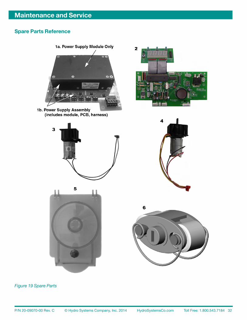
This chapter describes maintenance needed by the Sprite III and includes a list of spare parts:
• Routine Maintenance• Maintenance Visits• Pump Tube Replacement• Spare Parts List
Routine Maintenance
Routine maintenance on the Sprite III unit includes:
• Keeping the probe clean (probe mode operation only).• Keeping pump tubes fresh.• Keeping the unit clean.
Every Maintenance Visit
Each maintenance visit should include the following steps:
• Titrate the wash tank solution to verify that unit is holding accurate concentration.• Clean probe, if required.• Clean the unit cabinet with a damp cloth.• Check the pump tube’s condition and replace if needed.
Pump Tube Replacement
Replace pump tubes at regular maintenance intervals, well before the tube fails and ruptures.In the event that the tube does rupture, clean all product from the pump with a damp cloth.
• Loosen the pump front captive screw and remove the pump front.• Remove the old tube with barbed connectors and compression nuts.• Install the new tube with barbed connectors and compressions nuts oriented with flat sides facing towards the front.• Insert new tube from the left side of the pump, with pump spinner oriented in an 11/1 o’clock position.• Turn the spinner clockwise using a screwdriver as you press the pump tube in place.
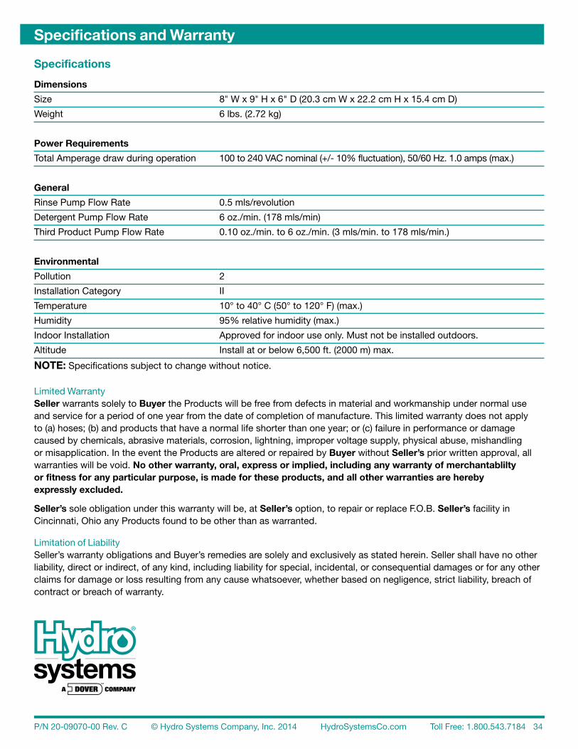
Size 8" W x 9" H x 6" D (20.3 cm W x 22.2 cm H x 15.4 cm D)
Weight 6 lbs. (2.72 kg)
Power Requirements
Total Amperage draw during operation 100 to 240 VAC nominal (+/- 10% fluctuation), 50/60 Hz. 1.0 amps (max.)
General
Rinse Pump Flow Rate 0.5 mls/revolution
Detergent Pump Flow Rate 6 oz./min. (178 mls/min)
Third Product Pump Flow Rate 0.10 oz./min. to 6 oz./min. (3 mls/min. to 178 mls/min.)
Environmental
Pollution 2
Installation Category II
Temperature 10° to 40° C (50° to 120° F) (max.)
Humidity 95% relative humidity (max.)
Indoor Installation Approved for indoor use only. Must not be installed outdoors.
Altitude Install at or below 6,500 ft. (2000 m) max.
NOTE: Specifications subject to change without notice.
Limited Warranty Seller warrants solely to Buyer the Products will be free from defects in material and workmanship under normal use and service for a period of one year from the date of completion of manufacture. This limited warranty does not apply to (a) hoses; (b) and products that have a normal life shorter than one year; or (c) failure in performance or damage caused by chemicals, abrasive materials, corrosion, lightning, improper voltage supply, physical abuse, mishandling or misapplication. In the event the Products are altered or repaired by Buyer without Seller’s prior written approval, all warranties will be void. No other warranty, oral, express or implied, including any warranty of merchantablilty or fitness for any particular purpose, is made for these products, and all other warranties are hereby expressly excluded.
Seller’s sole obligation under this warranty will be, at Seller’s option, to repair or replace F.O.B. Seller’s facility in Cincinnati, Ohio any Products found to be other than as warranted.
Limitation of Liability Seller’s warranty obligations and Buyer’s remedies are solely and exclusively as stated herein. Seller shall have no other liability, direct or indirect, of any kind, including liability for special, incidental, or consequential damages or for any other claims for damage or loss resulting from any cause whatsoever, whether based on negligence, strict liability, breach of contract or breach of warranty.