200
SPROCKETS Product Catalog www.tsubaki.ca
| Date post: | 04-Feb-2018 |
| Category: |
Documents |
| Upload: | trinhduong |
| View: | 266 times |
| Download: | 2 times |

©2013 U.S. Tsubaki Power Transmission, LLC. All Rights Reserved. Printed in U.S.A.
03/13 Rev. 0 L14010
SPROCKETS Product Catalog
SPROCKETS Product Catalog
w w w . t s u b a k i . c a
w w w . u s t s u b a k i . c o m
NOTE: IN ACCORDANCE WITH THE POLICY OF U.S. TSUBAKI POWER TRANSMISSION, LLC TO CONSISTENTLY IMPROVE ITS PRODUCTS, THE SPECIFICATIONS IN THIS CATALOG ARE SUBJECT TO CHANGE WITHOUT NOTICE.

Complete System Solutions Tsubaki offers complete drive system solutions that serve a variety of markets and applications around the world. Our complete offering of ANSI roller chain, engineered chain, sprockets, power transmission components, and cable & hose carrier systems offers single source capability to satisfy the most demanding application requirements.
Dedication to Quality Proven design, quality, and manufacturing systems assure each and every product shipped will meet the quality and durability expectations you expect from a world-class supplier. Tsubaki takes pride in the fact that our manufacturing facilities are ISO 9001: 2000 and ISO 14001 certified.
Tsubaki only uses the highest grade carbon steel material to assure long service life, abrasion resistance, and the ability to withstand heavy shock loading. Sprockets can also be manufactured utilizing special alloys or stainless steel materials for added corrosion resistance and food grade applications.
SPROCKET SOLUTIONS
Stock Sprocket Offering Tsubaki produces a broad range of sprockets to satisfy your application requirements. Stock product offerings are readily available, and can be supplied in the following pitch ranges and configurations:
• Pitch Range: ANSI 25 - 240• Type A Plain Bore (no hub extension)• Type B Plain Bore (one-sided hub extension)• Type C Plain Bore (two-sided hub extension)• Stainless Steel: ANSI 25 - 80 Pitch• Multi-Strand • TAPER-LOCK® and QD® Sprockets and Bushings• Double Pitch • Double Plus®
• Double Single• Idler Sprockets
2

www.tsubaki.ca
Markets and Applications Tsubaki sprockets are utilized worldwide in many markets and applications, including:
• Oil and Gas• Lumber• Mining• Primary Metals• Material Handling• Conveyor• Civil Engineering Projects
• Machine Tool• Marine• Packaging Machinery• Pulp and Paper• Food Processing• Forestry
3

SPROCKET SOLUTIONS MADE -TO - ORDER
Tsubaki MTO Sprockets
Engineering Capabilities
Tsubaki, and its a liates, have designed and manufactured Made-To-Order sprockets for over 35 years. Extensive design, engineering, and manufacturing capability allow Tsubaki to produce a wide variety of MTO sprocket products for a multitude of applications. rom one-off custom to high volume OEM sprocket requirements, Tsubaki has you covered.
Tsubaki has a broad range of engineering capabilities that enable the manufacture of complex MTO sprockets for your application requirements. Some of these capabilities include: • System design assessments• 2D/3D Cad Drawing Generation• ECD, ANSI, and British Standard Design • Custom tooth profiling• Solid, split, segmental, adjustable design
Large Engineering Class Segmental Sprocket with Split Hub
Triple roller chain sprocket with large finished bore and custom split design
Large Engineering Class Sprocket incorporating “Gap Tooth”
design for drive chain attachments Adjustable Segmental Rim Sprockets
4
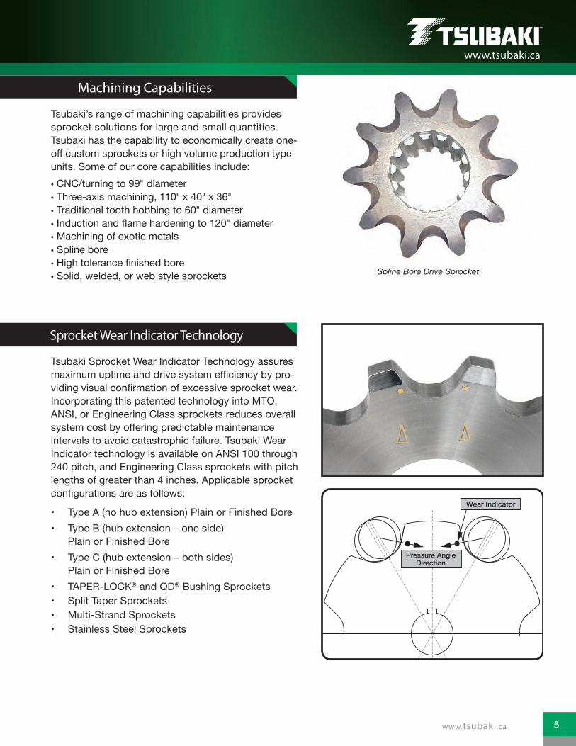
Spline Bore Drive Sprocket
Machining Capabilities
Sprocket Wear Indicator Technology
Tsubaki’s range of machining capabilities provides sprocket solutions for large and small quantities. Tsubaki has the capability to economically create one-off custom sprockets or high volume production type units. Some of our core capabilities include: • CNC/turning to 99" diameter• Three-axis machining, 110" x 40" x 36"• Traditional tooth hobbing to 60" diameter• Induction and ame hardening to 120 diameter• Machining of exotic metals• Spline bore • igh tolerance finished bore • Solid, welded, or web style sprockets
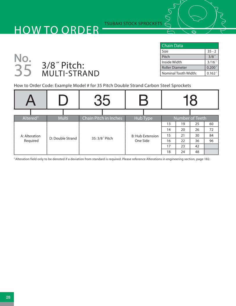
Tsubaki Sprocket Wear Indicator Technology assures maximum uptime and drive system e ciency by pro-viding visual confirmation of excessive sprocket wear. Incorporating this patented technology into MTO, ANSI, or Engineering Class sprockets reduces overall system cost by offering predictable maintenance intervals to avoid catastrophic failure. Tsubaki Wear Indicator technology is available on ANSI 100 through 240 pitch, and Engineering Class sprockets with pitch lengths of greater than 4 inches. Applicable sprocket configurations are as follows:
Type A (no hub extension) Plain or inished Bore Type B (hub extension one side)
Plain or Finished Bore Type C (hub extension both sides)
Plain or Finished Bore TAPER-LOCK® and QD® Bushing Sprockets Split Taper Sprockets Multi-Strand Sprockets Stainless Steel Sprockets
www.tsubaki.ca
Pressure AngleDirection
Wear Indicator
5www.tsubaki.ca

Distribution Network Tsubaki has partnered with over 1,500 National and Independent distributors in North America to assure that our products are readily available and supported in all of the geographical regions served. Our distributor network is trained on all of the Tsubaki products, and can offer the support and service you need to stay up and running.
SPROCKET SOLUTIONSCustomer Support Tsubaki’s trained and experienced customer service team, application engineers, field sales network, and design engineers ensure that you will get accurate and timely support for all of your power transmission needs. Tsubaki has global representation in over 70 countries around the world, providing comprehensive support required by our customers and markets we serve.
6

TABLE OF CONTENTSSprockets 101Complementary ProductsStock Sprocket ProductsNO. 25: 1/4˝ PITCHNO. 35: 3/8˝ PITCHNO. 41: 1/2˝ PITCHNO. 40: 1/2˝ PITCHNO. 50: 5/8˝ PITCHNO. 60: 3/4˝ PITCH NO. 80: 1˝ PITCHNO. 100: 1-1/4˝ PITCHNO. 120: 1-1/2˝ PITCHNO. 140: 1-3/4˝ PITCHNO. 160: 2˝ PITCHNO. 180: 2-1/4˝ PITCH NO. 200: 2-1/2˝ PITCHNO. 240: 3˝ PITCHNO. 2040: 1˝ PITCHNO. 2042: 1˝ PITCHNO. 2050: 1-1/4˝ PITCHNO. 2052: 1-1/4˝ PITCHNO. 2060: 1-1/2˝ PITCHNO. 2062: 1-1/2˝ PITCHNO. 2080: 2˝ PITCHNO. 2082: 2˝ PITCHDouble Plus Sprockets®
08 - 13
16 - 17
18 - 2122 - 3334 - 4142 - 5758 - 7374 - 8990 - 105106 - 117118 - 125126 - 133134 - 139140 - 141142 - 143144 - 145146 - 147148 - 149150 - 151152 - 153154 - 155156 - 157158 - 159160 - 161162
Bushings, Hubs, Idlers and Chain TensionersTAPER-LOCK® BushingsTAPER-LOCK® Weld-On HubsQD® BushingsQD® Weld-On HubsIdler SprocketsChain Tensioners
Engineering DataAlterationsSprocket HardeningSprocket Tooth DimensionsSprocket Pitch Diameter ConstantsSprocket Speed RatiosSprocket DiametersStandard Keyway and Set ScrewsTAPER-LOCK® Shallow Keyway DimensionsQD® Shallow Keyway DimensionsMaintenance ChecklistSafety WarningOther Sprocket ConsiderationsTerms and Conditions of Sale
163164 - 167168 - 169170 - 173174 - 175176 - 178 179 - 180
181182 - 185186187 188189190 - 192193
194195196197198 - 199200
www.tsubaki.ca
7

SPROCKETS 101
01
02
03
The following defines terminology and provides guidance to help select the best sprocket for a given application. In the event that further assistance is required, please call Tsubaki customer service at (800) 263 -7088.
Basic TerminologyANSI Chain Pitch: The term “chain pitch” refers to the roller pin center to roller pin center dimension of a given chain. The pitch is always measured in 1/8" increments. Please see Figure 1 for an illustration of how to measure chain pitch. Please see Table 1 for referencing ANSI Standard chain pitch sizes.
Caliper Diameter: The term “caliper diameter” refers to the dimension measured from sprocket tooth valley to sprocket tooth valley on the opposite side (180 ) of the sprocket. This dimension is used to measure the diameter of the sprocket plate (not including sprocket teeth). On sprockets that have an odd number of teeth, the measurement would be taken from the valley of one tooth to the valley as close to 180 on the opposite side of the sprocket. Please reference Figure 2 for an illustration of how this dimension is measured.
Table 1 - ANSI Standard Chain Pitch Table
Figure 1 - Chain pitch measurement points (P)
Figure 2 - Measuring caliper diameter
Sprocket Outside Diameter: Sprocket outside diameter is the measure-ment from sprocket tooth peak to sprocket tooth peak on the opposite (180 ) side of the sprocket. For sprockets with an odd number of teeth, the measurement would be taken from the peak of one sprocket tooth to the peak of a tooth as close to 180 degrees as possible. Please refer to Figure 3 for an illus-tration as to how this dimension is measured.
ANSI Standard Chain Pitch Size
Pitch # Pitch in IN Pitch # Pitch in IN25 1/4" 100 1-1/4"35 3/8 " 120 1-1/2"40 1/2" 140 1-3/4"41 1/2" 160 2"50 5/8" 180 2-1/4"60 3/4" 200 2-1/2"80 1" 240 3"
P P
8

04
05
06
07
08
Figure 3 - Measuring sprocket outside diameter
Figure 4 - Maximum bore diameter and thru bore
Figure 5 - Finished bore sprocket
Figure 6 - Stock sprocket hub styles
Maximum Bore Diameter: Refers to the maximum bore size diameter a sprocket can be machined to without compromising structural integrity. This term is associated with both “B” and “C” style sprockets. Please refer to Figure 4 for illustration.
Length Thru Bore: LTB Refers to the inside hub diameter and the length to which it was machined. This machined length must be long enough to accommodate the proper size keyway to withstand shear and torque stress induced by the rotating shaft. Please refer to Figure 4 for illustration.
Plain Bore: Associated with “A,” “B” and “C” style sprockets where there is no special machining performed to accommodate keyways or set screws, only a hole to accommodate shaft diameter. Please refer to Figure 6 for illustrations of Plain Bore sprockets.
Finished Bore: Associated with “B” and “C” style sprockets where the inside diameter of the hub is machined with a standard keyway and two set screws. Finished bore hubs can also be machined to specific requirements depending on the needs of the application. Please refer to Figure 5 for an illustration.
Sprocket Hub Style: Tsubaki manufacturers various sprocket hub styles to meet the ap-plication requirements of our customers. Please refer to Figure 6 for the various stock style hub configurations offered by Tsubaki.
TOOTH(NOMINAL)
OU
TSID
ED
IAM
ETE
R
HU
B D
IAM
ETE
R
MIN
BO
RE
LTB
STYLE STYPE B
STYLE ETYPE B
TOOTH(NOMINAL)
OU
TSID
ED
IAM
ETE
R
HU
B D
IAM
ETE
R
MA
X B
OR
E
LTB
SPROCKETS 101
BO
RE
BO
RE
BO
TTO
M D
IAM
ETE
R
CALIPER DIAMETER
PIT
CH
CIR
CLE
DIA
ME
TER
OU
TSID
E D
IAM
ETE
R
BO
RE
HU
BD
IAM
ETE
R
BO
RE
HU
BD
IAM
ETE
R
OU
TSID
ED
IAM
ETE
R
OU
TSID
ED
IAM
ETE
R
OU
TSID
ED
IAM
ETE
R
OU
TSID
ED
IAM
ETE
R
OU
TSID
ED
IAM
ETE
RB
OR
E
HU
BD
IAM
ETE
R
STYLE DTYPE B
LTB
TOOTH (NOMINAL)
BO
RE
BO
RE
BO
RE
BO
RE
HU
BD
IAM
ETE
R
HU
BD
IAM
ETE
R
HU
BD
IAM
ETE
R
LTB
STYLE DTYPE C
LTB
STYLE ETYPE B
LTB
STYLE STYPE B
TYPE A
TOOTH(NOMINAL)
TOOTH(NOMINAL)
TOOTH(NOMINAL)
TOOTH(NOMINAL)
STYLE STYPE B
LTB
TOOTH (NOMINAL)
OU
TSID
ED
IAM
ETE
RB
OR
E
BO
RE
OU
TSID
ED
IAM
ETE
R
TYPE A
TOOTH (NOMINAL)
HU
BD
IAM
ETE
R
OU
TSID
ED
IAM
ETE
R
BO
RE
HU
BD
IAM
ETE
R
STYLE ETYPE B
LTB
TOOTH (NOMINAL)
STYLE STYPE B
LTB
TOOTH (NOMINAL)
OU
TSID
ED
IAM
ETE
R
BO
RE
HU
BD
IAM
ETE
R
HU
BD
IAM
ETE
R
Y
OU
TSID
ED
IAM
ETE
R
F
X
STYLE ETYPE C
LTB
L
STYLE STYPE B
X
L
Y
LTB
OU
TSID
ED
IAM
ETE
R
HU
BD
IAM
ETE
R
Y
HU
BD
IAM
ETE
R
OU
TSID
ED
IAM
ETE
R
F F
STYLE ETYPE B
X
L
LTBTOOTH(NOMINAL)
TOOTH(NOMINAL)
TOOTH(NOMINAL)
STYLE STYPE B
LTB
TOOTH(NOMINAL)
OU
TSID
ED
IAM
ETE
R
OU
TSID
ED
IAM
ETE
R
HU
BD
IAM
ETE
R
HU
BD
IAM
ETE
R
STYLE ETYPE B
LTB
TOOTH(NOMINAL)
9

Small and Large Roller Double Pitch Sprockets: Used with double pitch conveyor series roller chains. These chains are available with either the standard small roller diameter (i.e.: 2040, 2050, 20 0, 2080, 2100) or a larger diameter chain roller style (i.e.: 2042, 2052, 20 2, 2082, 2102). Sprockets are available from stock to accommodate either style. This type of sprocket is primarily used in conveying applications where torque requirements are lower, and long service life is critical. Please refer to Figure 7 for an illustration of a standard and double pitch sprocket for comparison purposes.
Multiple-Strand Sprockets: This type of sprocket is commonly used in applications where higher torque and power requirements are needed. The spacing between the rows of teeth corresponds with the center-line of chain strands. Due to the added width of chain, the “LTB” of multiple strand sprockets is correspondingly longer. This style of sprocket is available in 40 through 1 0 chain pitch with plain, finished or TAPER-LOCK®/QD® style hubs. Please refer to Figure 8 for an illustration of a Multiple-Strand sprocket. Figure 8 - Multiple-Strand sprockets
Figure 7 - Small and large roller double pitch sprockets
Figure 9 - DOUBLE PLUS® sprockets
DOUBLE PLUS® Sprockets: This type of sprocket is specifically designed to work with DOUBLE PLUS® chain. This style of sprocket is used in conveyor applications where product on the conveyor is propelled at twice speed of the drive system powering the conveyor. The main benefit of incorporating DOUBLE PLUS® chain and sprockets is less noise and longer chain life. Please refer to Figure 9 for an illustration of a DOUBLE PLUS® sprocket.
SPROCKETS 101
09
10
11
10

QD® Sprockets: This type of sprocket is used in applications where higher working loads are prevalent, and high clamp loading on the drive shaft is desirable. Sprockets with tapered bushings will fall into the QD®, Split-Taper or TAPER-LOCK® family. QD® bushings are anged, and most commonly utilize large anchor bolts around the circumference of the ange to retain itself to the sprocket. However, this style of bushing is also available in a weld on hub configuration. One of the primary advantages the QD® bushing offers is its ease of installation and removal. It also provides superior clamp force, and aligns the sprocket 900 to the drive shaft to assure proper alignment. Please refer to Figure 10 for an illustration of a QD® sprocket.
TAPER-LOCK® Sprockets: TAPER-LOCK® bushings are similar to QD® style bushings in that they both utilize a split through the taper and ange to provide a true clamp on the shaft that is equivalent to a shrink fit. This type of bushing is retained to the sprocket with a series of set screws on the outside diameter of the bushing running parallel to the shaft, or can be welded to the sprocket itself. With TAPER-LOCK® bushings, there is no need for a set screw over the drive shaft key. TAPER-LOCK® bushings offer exibility in that they allow multiple sized
bores for a single bushing size. Please refer to Figure 11 for an illustration of a TAPER-LOCK® sprocket.
Figure 11 - TAPER-LOCK® sprocket
Figure 10 - QD® sprocket
Figure 12 - Steel Split sprocket
Steel Split Sprockets: Split sprockets are slit through the entire diameter of the sprocket to allow ease of installation and removal. The sprocket halves are held together by bolts located on either side of the hub. This particular style is available in chain pitch sizes of 40 through 240, and bore diameters of 3/4" through 6" depending on chain pitch selected. Figure 12 provides an illustration of a steel split sprocket.
SPROCKETS 101
14
13
12
11

British Standard Sprockets: This style of sprocket is similar to an ANSI style sprocket with the exception of the fact that it is designed to propel British Standard Chain. British Standard Chain has slightly different dimensions with regard to chain pitch and roller diameter. ANSI Standard chain pitch is measured in 1/8" increments (pin to pin), whereas British Standard follows a 1/16" pin to pin spacing. Please see Figure 13 for an illustration of how to measure British Standard chain pitch.
Double Single Sprockets: This type of sprocket is commonly used in applications where two or more items are powered by a common drive shaft. The space between the sprocket plates is wider than a multi-strand sprocket, and allows two separate strands of chain to engage without contacting each other. With this type of sprocket, one strand of chain may exit in a different direction than the other. For example, one strand exiting towards the ceiling and the other running parallel to the oor. Please refer to Figure 14 for an illustration of a Double Single sprocket. Figure 14 - Double Single Sprocket
Figure 13 - Measuring British Standard Chain
Idler Sprockets: This type of sprocket is used in applications where the drive chain may experience slack due to long lengths, non-adjustability of the driven shaft, or where the chain has to be guided around an obstruction. Use of Idler Sprockets prevents chain whipping and uneven distribution of load. This type of sprocket can also be used in applications where the drive chain may experience direction reversal, or in applications where the chain may experience whipping. Having idler sprockets touching the outside of the chain would be beneficial. Please refer to Figure 15 for an illustration of an Idler Sprocket.
P P
SPROCKETS 101
15
16
17
Figure 15 - Idler Sprocket
12

How to Order Code: The following decodes the model number for a given Tsubaki Stock Sprocket product. The following example should be used to decipher the characteristics and features associated with a given sprocket.
Altered!!: The term Altered applies to a sprocket that requires a minor modification to the standard configuration to fulfill the requirements of the application at hand. Some examples of common alterations include: rebore to a different size than standard, different set screw location than standard, drilling of holes into sprocket plate for accessory mounting, non-standard keyway size, etc. A complete list of common alterations is available in the engineering section of this catalog. It should be noted that adding the prefix A is used only when an alteration is required. It is not necessary for standard products and only applies when a non-standard feature is required.
Fraction Legend for Hub Bore Size: The following table should be used to define the hub bore size associated with inished Bore stock sprocket product. Note that a letter designator is used to represent a fractional dimension. For example: a 1B hub bore equates to a sprocket bore of 1.125" inside diameter.
Letter Designator Fractional Size Decimal SizeA 1/16" 0.0625"B 1/8" 0.1250"C 3/16" 0.1875"D 1/4" 0.2500"E 5/16" 0.3125"F 3/8" 0.3750"G 7/16" 0.4375"H 1/2" 0.5000"I 9/16" 0.5625"J 5/8" 0.6250"K 11/16" 0.6875"L 3/4" 0.7500"M 13/16" 0.8125 "P 7/8" 0.8750"R 15/16" 0.9375"
SPROCKETS 101
20
19
18
A 35 B TL 18Altered !! Chain Pitch in Inches Hub Type TAPER-LOCK® Number of Teeth
A: Alteration Required
35: 3/8˝ Pitch B: Hub Extension One Side TAPER-LOCK® hub
18 22 2619 23 2820 24 3021 25 32
13

SPROCKETS SOLUTIONSWHY TSUBAKI SPROCKETS ARE YOUR BEST CHOICE...
Tsubaki stock sprockets are made from 1045 cold rolled carbon steel, and are black oxide coated for maximum corrosion resistance and durability. No powdered metal is used.
All Tsubaki stock sprockets have hardened teeth to RC 5 - 50 standard on ANSI 35 - 80 pitch. This ensures long service life with minimal wear.
Tsubaki finished bore sprockets come with a keyway and two set screws standard.
14

All hard edges are chamfered and de-burred for the best fit.
Tsubaki offers stock plain bore, finished bore, and altered sprockets for rapid delivery to meet your application require-ments fast!!!
Tsubaki sprockets are available in ANSI standard or British Standard pitch specifications.
Standard set screw placement directly over the keyway and at 90 to the keyway ensures the sprocket will hold position throughout its time in service.
15www.tsubaki.ca

POWER-LOCK®
TORQUE SHIELD
TORQUE LIMITER
Tsubaki PO ER-LOCK® technology provides a keyless sprocket to drive shaft locking solution for applications that experience load reversal and high torque loading. PO ER-LOCK® eliminates the need for costly machining associated with long keyways, spline bores, threaded shafts and grooves or steps to prevent premature failure. PO ER-LOCK® technology offer fast installation and removal, and can be used on sprockets, gears, pulleys, timing cams, and rollers to increase shaft strength, and ensure long service life.
Tsubaki Torque Shield provides mechanical drive system protection for sophisticated applications that may experience overloading or jamming. Applications that demand consistent and predictable trip settings with quick resetting will benefit from this device. Torque Shield is easy to set and adjust with a built- in scale and indicator that have distinct torque set-tings for easy verification. Tsubaki offers four different series of Torque Shield products to support all of your drive system needs.
Refined by Tsubakimoto for over 40 years, the Torque Limiter is a simple and inexpensive mechanical device that limits damage to equipment when an unexpected increase in torque occurs because of a jam or overload situation. Easy to install, the Torque Limiter attaches to a shaft and holds the sprocket, gear, or sheave. A frictional system, the Torque Limiter reacts instantly when there is a jam by slipping and absorbing the brunt of the force, thus preventing the increase in power from damaging your equipment. Let Tsubaki’s family of Torque Limiters provide an economical solution for protecting your drive system.
COMPLEMENTARY PRODUCTS
16

LINEAR SHIELD
SHOCK RELAY®
Designed for pushing/pulling applications, Tsubaki’s Linear Shield provides system protection for equipment used in straight line applications. Machine tool, press applications, pick and place, and other linear system operations are protected from overloading by a simple ball and groove design. Compact design, ease of installation, and quick resetting makes this device ideal for limiting downtime and preserving critical equipment operation.
Pioneered by Tsubaki, the Shock Relay® protects your equipment against unexpected shock loads and overloads before system damage occurs. The Shock Relay® adapts to virtually any type of equipment that’s driven by an electric motor. The purpose of the Shock Relay® is to protect the mechanical parts of the equipment by monitoring drive motor current, shutting down the equipment when the loads exceed the user set limits. Unlike mechanical protection devices, there is no physical re-setting required. The Tsubaki Shock Relay® simply resets at the press of a button. Let Tsubaki’s family of Shock Relays keep your production up and running.
COMPLEMENTARY PRODUCTS
17

!! Alteration field only to be denoted if a deviation from standard is required. Please reference Alterations in engineering section, page 182.
A 25 A 36Altered !! Chain Pitch in Inches Hub Type Number of Teeth
A: Alteration Required
25: 1/4˝ Pitch
A: No Hub Extension
15 21 28 4516 22 30 4817 23 32 5418 24 35 6019 25 36 7220 26 40
B: Hub Extension One Side
9 17 25 4510 18 26 4811 19 28 5412 20 30 60
13 21 32 72
14 22 35
15 23 36
16 24 40
Chain DataSize 25Pitch 1/4˝Inside Width 1/8˝Roller Diameter 0.130˝Nominal Tooth Width: 0.110˝
No.1/4˝ Pitch: PLAIN BORE
How to Order Code: Example Model # for 25 Pitch Plain Bore Sprockets
25
HOW TO ORDERTSUBAKI STOCK SPROCKETS
LTBLTB
OU
TSID
EDI
AMET
ER
OU
TSID
EDI
AMET
ER
OU
TSID
EDI
AMET
ER
BORE
BORE
BORE
HU
BDI
AMET
ER
HU
BDI
AMET
ER
STYLE ETYPE B
STYLE STYPE B
TYPE A
TOOTH(NOMINAL)
TOOTH(NOMINAL)
TOOTH(NOMINAL)
.110NOMINAL
.110NOMINAL
.110NOMINAL
18

No. 25 Plain Bore Sprocket Diameters Type “A” Plain Bore Type “B” Plain Bore
No. Teeth
Outside Diameter
Pitch Diameter
Caliper Diameter
Plain Bore
Wt. Lbs.
Plain Bore
MAX Bore*
Hub Dia. LTB Style Wt.
Lbs.
9 0.837 0.731 0.591 NS NS 0.250 0.250 0.438 0.500 S 0.03
10 0.919 0.809 0.679 NS NS 0.250 0.250 0.500 0.500 S 0.03
11 1.002 0.870 0.748 NS NS 0.250 0.313 0.563 0.500 S 0.04
12 1.083 0.996 0.836 NS NS 0.250 0.375 0.625 0.500 S 0.06
13 1.167 1.045 0.907 NS NS 0.250 0.438 0.781 0.500 S 0.07
14 1.246 1.124 0.994 NS NS 0.250 0.563 0.813 0.500 S 0.08
15 1.326 1.203 1.066 0.250 0.040 0.250 0.563 0.891 0.500 S 0.10
16 1.407 1.282 1.152 0.250 0.040 0.250 0.563 0.969 0.500 S 0.12
17 1.487 1.361 1.225 0.250 0.040 0.250 0.625 1.031 0.500 S 0.14
18 1.568 1.440 1.310 0.250 0.040 0.250 0.750 1.125 0.500 S 0.16
19 1.648 1.519 1.383 0.250 0.040 0.250 0.813 1.219 0.500 S 0.19
20 1.729 1.598 1.468 0.250 0.040 0.250 0.875 1.281 0.625 S 0.25
21 1.809 1.678 1.543 0.375 0.040 0.250 0.875 1.375 0.625 S 0.28
22 1.889 1.757 1.627 0.375 0.060 0.250 0.938 1.438 0.625 S 0.31
23 1.969 1.836 1.702 0.375 0.060 0.250 1.000 1.500 0.625 S 0.32
24 2.049 1.915 1.785 0.375 0.080 0.375 1.000 1.500 0.625 S 0.33
25 2.129 1.995 1.861 0.375 0.080 0.375 1.000 1.500 0.625 S 0.34
26 2.209 2.074 1.944 0.375 0.090 0.375 1.000 1.500 0.625 S 0.35
28 2.369 2.233 2.103 0.375 0.100 0.375 1.000 1.500 0.625 S 0.36
30 2.529 2.392 2.262 0.375 0.120 0.375 1.000 1.500 0.625 S 0.38
32 2.688 2.551 2.421 0.375 0.140 0.375 1.000 1.500 0.625 S 0.40
35 2.928 2.789 2.656 0.375 0.160 0.375 1.000 1.500 0.625 S 0.46
36 3.008 2.889 2.739 0.375 0.180 0.375 1.000 1.500 0.750 S 0.50
40 3.327 3.187 3.057 0.500 0.200 0.500 1.375 2.000 0.750 E 0.53
45 3.725 3.584 3.452 0.500 0.250 0.500 1.375 2.000 0.750 E 0.56
48 3.964 3.823 3.693 0.500 0.320 0.500 1.375 2.000 0.750 E 0.56
54 4.442 4.300 4.170 0.500 0.380 0.500 1.375 2.000 0.750 E 1.00
60 4.920 4.777 4.647 0.500 0.540 0.500 1.375 2.000 0.750 E 1.10
72 5.876 5.732 5.602 0.500 0.740 0.500 1.375 2.000 0.750 E 1.30
Tsubaki Stock Sprockets
PLAIN BORE SPROCKET DIMENSIONSNo. 25
* Dimensions shown allow for standard keyway with set screw at 90 degreesNS = Non Stock
All dimensions in inches unless noted.
19www.tsubaki.ca

How to Order Code: Example Model # for 25 Pitch Plain Bore Stainless Steel Sprockets
!! Alteration field only to be denoted if a deviation from standard is required. Please reference Alterations in engineering section, page 182.
A 25 B 14 SSAltered !! Chain Pitch in Inches Hub Type Number of Teeth Material
A: Alteration Required
25: 1/4˝ Pitch B: Hub Extension One Side
9 15 21 28
SS: 304 Stainless Steel Construction
10 16 22 3011 17 23 3612 18 24 4013 19 25 4514 20 26 60
Chain DataSize 25SSPitch 1/4˝Inside Width 1/8˝Roller Diameter 0.130˝Nominal Tooth Width: 0.110˝
No.1/4˝ Pitch: STAINLESS STEEL PLAIN BORE25
HOW TO ORDERTSUBAKI STOCK SPROCKETS
20

No. 25 Stainless Steel Sprocket Diameters Type “B” Plain Bore
No. Teeth
Outside Diameter
Pitch Diameter
Caliper Diameter
Plain Bore
MAX Bore*
Hub Dia. LTB Wt.
Lbs.
9 0.837 0.731 0.591 0.250 0.250 0.438 0.500 0.03
10 0.919 0.809 0.679 0.250 0.250 0.500 0.500 0.03
11 1.002 0.870 0.748 0.250 0.313 0.563 0.500 0.03
12 1.083 0.966 0.836 0.250 0.375 0.625 0.500 0.06
13 1.167 1.045 0.907 0.250 0.438 0.719 0.500 0.07
14 1.246 1.124 0.994 0.250 0.563 0.813 0.500 0.08
15 1.326 1.203 1.066 0.250 0.563 0.891 0.500 0.10
16 1.407 1.282 1.152 0.250 0.563 0.969 0.500 0.12
17 1.487 1.361 1.225 0.250 0.625 1.031 0.500 0.14
18 1.568 1.440 1.310 0.250 0.750 1.125 0.500 0.16
19 1.648 1.519 1.383 0.250 0.813 1.219 0.500 0.19
20 1.729 1.598 1.468 0.250 0.875 1.281 0.625 0.25
21 1.809 1.678 1.543 0.250 0.875 1.375 0.625 0.28
22 1.889 1.757 1.627 0.250 0.938 1.438 0.625 0.31
23 1.969 1.836 1.702 0.250 1.000 1.500 0.625 0.32
24 2.049 1.915 1.785 0.375 1.000 1.500 0.625 0.33
25 2.129 1.995 1.861 0.375 1.000 1.500 0.625 0.34
26 2.209 2.074 1.944 0.375 1.000 1.500 0.625 0.35
28 2.369 2.233 2.103 0.375 1.000 1.500 0.625 0.36
30 2.529 2.392 2.262 0.375 1.000 1.500 0.625 0.38
36 3.008 2.869 2.739 0.375 1.000 1.500 0.750 0.50
40 3.327 3.187 3.057 0.500 1.375 2.000 0.750 0.53
45 3.725 3.584 3.452 0.500 1.375 2.000 0.750 0.56
60 4.920 4.777 4.647 0.500 1.375 2.000 0.750 1.10
Tsubaki Stock Sprockets
STAINLESS STEEL SPROCKET DIMENSIONSNo. 25
* Dimensions shown allow for standard keyway with set screw at 90 degrees
LTBLTB
OU
TSID
EDI
AMET
ER
OU
TSID
EDI
AMET
ER
OU
TSID
EDI
AMET
ER
BORE
BORE
BORE
HU
BDI
AMET
ER
HU
BDI
AMET
ER
STYLE ETYPE B
STYLE STYPE B
TYPE A
TOOTH(NOMINAL)
TOOTH(NOMINAL)
TOOTH(NOMINAL)
.110NOMINAL
All dimensions in inches unless noted.
21www.tsubaki.ca

!! Alteration field only to be denoted if a deviation from standard is required. Please reference Alterations in engineering section, page 182.
A 35 A 24Altered !! Chain Pitch in Inches Hub Type Number of Teeth
A: Alteration Required
35: 3/8˝ Pitch
A: No Hub Extension
15 24 40 8416 25 42 9617 26 45 11218 27 4819 28 5420 30 6021 32 7022 35 7223 36 80
B: Hub Extension One Side
8 18 28 609 19 30 70
10 20 32 7211 21 35 8012 22 36 8413 23 40 9614 24 42 11215 25 4516 26 4817 27 54
Chain DataSize 35Pitch 3/8˝Inside Width 3/16˝Roller Diameter 0.200˝Nominal Tooth Width: 0.168˝
No.3/8˝ Pitch: PLAIN BORE
How to Order Code: Example Model # for 35 Pitch Plain Bore Carbon Steel Sprockets
35
HOW TO ORDERTSUBAKI STOCK SPROCKETS
LTBLTB
OU
TSID
EDI
AMET
ER
OU
TSID
EDI
AMET
ER
OU
TSID
EDI
AMET
ER
BORE
BORE
BORE
HU
BDI
AMET
ER
HU
BDI
AMET
ER
STYLE ETYPE B
STYLE STYPE B
TYPE A
TOOTH(NOMINAL)
TOOTH(NOMINAL)
TOOTH(NOMINAL)
.168NOMINAL
.168NOMINAL
.168NOMINAL
22

No. 35 Plain Bore Sprocket Dia. Type “A” Plain Bore Type “B” Plain Bore
No. Teeth
Outside Dia.
Pitch Dia.
Caliper Dia.
Plain Bore
Wt. Lbs.
Plain Bore
MAX Bore*
Hub Dia. LTB Style Wt.
Lbs.
8 1.130 0.980 0.780 NS NS 0.375 0.375 0.750 ¨ 0.750 S 0.07
9 1.260 1.097 0.880 NS NS 0.375 0.375 0.844 ¨ 0.750 S 0.09
10 1.380 1.214 1.014 NS NS 0.375 0.563 0.969 ¨ 0.750 S 0.14
11 1.500 1.331 1.117 NS NS 0.375 0.563 1.063 ¨ 0.750 S 0.17
12 1.630 1.449 1.249 NS NS 0.500 0.563 1.219 ¨ 0.750 S 0.20
13 1.750 1.567 1.356 NS NS 0.500 0.688 1.250 ¨ 0.750 S 0.23
14 1.870 1.685 1.485 NS NS 0.500 0.875 1.250 0.750 S 0.25
15 1.990 1.804 1.594 0.500 0.110 0.500 0.875 1.344 0.750 S 0.29
16 2.110 1.922 1.722 0.500 0.120 0.500 0.938 1.469 0.750 S 0.35
17 2.230 2.041 1.832 0.500 0.140 0.500 1.063 1.594 0.750 S 0.42
18 2.350 2.160 1.960 0.500 0.160 0.500 1.188 1.719 0.750 S 0.48
19 2.470 2.279 2.071 0.500 0.170 0.500 1.250 1.844 0.750 S 0.54
20 2.590 2.397 2.197 0.500 0.190 0.500 1.313 1.938 0.750 S 0.59
21 2.710 2.516 2.309 0.500 0.210 0.500 1.375 2.000 0.875 S 0.80
22 2.830 2.635 2.435 0.500 0.240 0.500 1.375 2.000 0.875 S 0.80
23 2.950 2.754 2.548 0.500 0.260 0.500 1.375 2.000 0.875 S 0.82
24 3.070 2.873 2.673 0.500 0.280 0.500 1.375 2.000 0.875 S 0.88
25 3.190 2.992 2.786 0.500 0.310 0.500 1.375 2.000 0.875 S 0.88
26 3.310 3.111 2.911 0.500 0.330 0.500 1.375 2.000 0.875 E 0.90
27 3.430 3.230 3.025 0.500 0.360 0.500 1.375 2.000 0.875 E 0.94
28 3.550 3.349 3.149 0.500 0.380 0.500 1.375 2.000 0.875 E 0.94
30 3.790 3.588 3.388 0.500 0.440 0.500 1.375 2.000 1.000 E 1.02
32 4.030 3.826 3.626 0.625 0.500 0.500 1.375 2.000 1.000 E 1.24
35 4.390 4.184 3.979 0.625 0.610 0.625 1.500 2.250 1.000 E 1.50
36 4.510 4.303 4.103 0.625 0.640 0.625 1.500 2.250 1.000 E 1.56
40 4.990 4.780 4.580 0.594 0.790 0.625 1.500 2.250 1.000 E 1.62
42 5.230 5.018 4.818 0.594 0.900 0.625 1.500 2.250 1.000 E 1.68
45 5.590 5.376 5.173 0.594 1.000 0.625 1.500 2.250 1.000 E 1.78
48 5.950 5.734 5.534 0.594 1.100 0.625 1.500 2.250 1.000 E 1.88
54 6.660 6.449 6.249 0.594 1.400 0.625 1.500 2.250 1.000 E 2.20
60 7.380 7.165 6.965 0.594 1.800 0.750 1.500 2.250 1.000 E 2.48
70 8.580 8.358 8.158 0.719 2.400 0.750 1.500 2.250 1.000 E 3.12
72 8.810 8.597 8.397 0.719 2.600 0.750 1.500 2.250 1.000 E 3.42
80 9.770 9.552 9.352 0.719 3.200 0.750 1.500 2.250 1.000 E 3.82
84 10.250 10.029 9.829 0.719 3.500 0.750 1.500 2.250 1.000 E 4.24
96 11.680 11.461 11.261 0.719 4.600 0.750 1.500 2.250 1.000 E 5.16
112 13.590 13.371 13.171 0.719 6.300 0.750 1.500 2.250 1.000 E 6.70
Tsubaki Stock Sprockets
PLAIN BORE SPROCKET DIMENSIONSNo. 35
* Dimensions shown allow for standard keyway with set screw at 90 degrees¨ Has recessed groove in hub for chain clearanceNS = Non Stock
All dimensions in inches unless noted.
23www.tsubaki.ca

How to Order Code: Example Model # for 35 Pitch Plain Bore Stainless Steel Sprockets
!! Alteration field only to be denoted if a deviation from standard is required. Please reference Alterations in engineering section, page 182.
A 35 B 17 SSAltered !! Chain Pitch in Inches Hub Type Number of Teeth Material
A: Alteration Required
35: 3/8˝ Pitch B: Hub Extension One Side
9 15 21 28
SS: 304 Stainless Steel Construction
10 16 22 3011 17 23 3512 18 24 4013 19 25 4514 20 26 60
Chain DataSize 35SSPitch 3/8˝Inside Width 3/16˝Roller Diameter 0.200˝Nominal Tooth Width: 0.168˝
No.3/8˝ Pitch: STAINLESS STEEL PLAIN BORE35
HOW TO ORDERTSUBAKI STOCK SPROCKETS
24

No. 35 Stainless Steel Sprocket Diameters Type “B” Plain Bore
No. Teeth
Outside Diameter
Pitch Diameter
Caliper Diameter
Plain Bore
MAX Bore*
Hub Dia. LTB Hub
Style Wt. Lbs.
9 1.260 1.097 0.880 0.375 0.375 0.844 ¨ 0.750 S 0.10
10 1.380 1.214 1.014 0.375 0.563 0.969 ¨ 0.750 S 0.15
11 1.500 1.331 1.117 0.375 0.563 1.063 ¨ 0.750 S 0.20
12 1.630 1.449 1.249 0.500 0.563 1.219 ¨ 0.750 S 0.22
13 1.750 1.567 1.356 0.500 0.688 1.250 ¨ 0.750 S 0.25
14 1.870 1.685 1.485 0.500 0.875 1.250 0.750 S 0.26
15 1.990 1.804 1.594 0.500 0.875 1.344 0.750 S 0.30
16 2.110 1.922 1.722 0.500 0.938 1.469 0.750 S 0.40
17 2.230 2.041 1.832 0.500 1.063 1.594 0.750 S 0.43
18 2.350 2.160 1.960 0.500 1.188 1.719 0.750 S 0.50
19 2.470 2.279 2.071 0.500 1.250 1.844 0.750 S 0.56
20 2.590 2.397 2.197 0.500 1.313 1.938 0.750 S 0.68
21 2.710 2.516 2.309 0.500 1.375 2.000 0.875 S 0.80
22 2.830 2.635 2.435 0.500 1.375 2.000 0.875 S 0.82
23 2.950 2.754 2.548 0.500 1.375 2.000 0.875 S 0.87
24 3.070 2.873 2.673 0.500 1.375 2.000 0.875 S 0.89
25 3.190 2.992 2.786 0.500 1.375 2.000 0.875 S 0.91
26 3.310 3.111 2.911 0.500 1.375 2.000 0.875 S 0.93
28 3.550 3.349 3.149 0.500 1.375 2.000 0.875 E 1.00
30 3.790 3.588 3.388 0.500 1.375 2.000 0.875 E 1.06
35 4.390 4.184 3.979 0.625 1.500 2.250 0.875 E 1.56
40 4.990 4.780 4.580 0.625 1.500 2.250 1.000 E 1.70
45 5.590 5.376 5.173 0.625 1.500 2.250 1.000 E 2.18
60 7.380 7.165 6.965 0.750 1.500 2.250 1.000 E 3.00
Tsubaki Stock Sprockets
STAINLESS STEEL SPROCKET DIMENSIONSNo. 35
* Dimensions shown allow for standard keyway with set screw at 90 degrees¨ Has recessed groove in hub for chain clearance
LTBLTB
OU
TSID
EDI
AMET
ER
OU
TSID
EDI
AMET
ER
OU
TSID
EDI
AMET
ER
BORE
BORE
BORE
HU
BDI
AMET
ER
HU
BDI
AMET
ER
STYLE ETYPE B
STYLE STYPE B
TYPE A
TOOTH(NOMINAL)
TOOTH(NOMINAL)
TOOTH(NOMINAL)
LTB
OU
TSID
EDI
AMET
ER
BORE
HU
BDI
AMET
ER
STYLE DTYPE B
TOOTH(NOMINAL)
.168NOMINAL
.168NOMINAL
All dimensions in inches unless noted.
25www.tsubaki.ca

** Hub bore size should be selected from dimensional table on the following page. Bore sizes that are not listed for a given number of sprocket teeth may be available per request as Altered.
35 B 24 F - 1BChain Pitch in Inches Hub Type Number of Teeth Finished Bore Hub Bore**
35: 3/8˝ Pitch B: Hub Extension One Side
9 18 27 48
F: Hub Extension Machined with keyway and two set screws
F 3/8" (0.375")10 19 28 54 H 1/2" (0.500")11 20 30 60 J 5/8" (0.625")12 21 32 70 L 3/4" (0.750")13 22 35 72 P 7/8" (0.875")14 23 36 80 1 1" (1.000")15 24 40 84 1B 1-1/8" (1.125")16 25 42 96 1C 1-3/16" (1.188")
17 26 45 112 1D 1-1/4" (1.250")
No.3/8˝ Pitch: FINISHED BORE
How to Order Code: Example Model # for 35 Pitch Finished Bore Carbon Steel Sprockets
35
HOW TO ORDERTSUBAKI STOCK SPROCKETS
Chain DataSize 35Pitch 3/8˝Inside Width 3/16˝Roller Diameter 0.200˝Nominal Tooth Width: 0.168˝
OU
TSID
EDI
AMET
ER
BORE
HU
BDI
AMET
ER
STYLE ETYPE B
LTB
TOOTH (NOMINAL)
STYLE STYPE B
LTB
TOOTH (NOMINAL)
OU
TSID
EDI
AMET
ER
BORE
HU
BDI
AMET
ER
.168NOMINAL
.168NOMINAL
26

No. 35 Finished Bore Sprocket Dia. Type “F” Bored to Shaft Size (includes standard keyway and two set screws)**
No. Teeth
Outside Dia.
Pitch Dia.
Caliper Dia. .3
75˝ *
*
.500
˝ **
.625
˝
.750
˝
.875
˝
1.00
0˝
1.12
5˝
1.18
75˝
1.25
0˝
9 1.260 1.097 0.880 •
10 1.380 1.214 1.014 • • • ¢
11 1.500 1.331 1.117 • • • ¢ • ¢
12 1.630 1.449 1.249 • • • ¢
13 1.750 1.567 1.356 • • •
14 1.870 1.685 1.485 • • •
15 1.990 1.804 1.594 • • • • • ¢
16 2.110 1.922 1.722 • • • • • ¢
17 2.230 2.041 1.832 • • • • •
18 2.350 2.160 1.960 • • • • •
19 2.470 2.278 2.071 • • • •
20 2.590 2.397 2.197 • • • •
21 2.710 2.516 2.309 • • • •
22 2.830 2.635 2.435 • • • •
23 2.950 2.754 2.548 • • • •
24 3.070 2.873 2.673 • • • •
25 3.190 2.992 2.786 • • • •
26 3.310 3.111 2.911 • • • • • • •
27 3.430 3.230 3.025 • • • • • • •
28 3.550 3.349 3.149 • • • • • • •
30 3.790 3.588 3.388 • • • • • • •
32 4.030 3.826 3.626 • • • • • • •
35 4.390 4.184 3.979 • • • • • • •
36 4.510 4.303 4.103 • • • • • • •
40 4.990 4.780 4.580 • • • • • • •
42 5.230 5.018 4.818 • • • • • • •
45 5.590 5.376 5.173 • • • • • • •
48 5.950 5.734 5.534 • • • • • • •
54 6.660 6.449 6.249 • • • • • • •
60 7.380 7.165 6.965 • • • • • •
70 8.580 8.358 8.158 • • • • • •
72 8.810 8.597 8.397 • • • • • •
80 9.770 9.552 9.352 • • • • • •
84 10.250 10.029 9.829 • • • • • •
96 11.680 11.461 11.261 • • • • • •
112 13.590 13.371 13.171 • • • • • •
FINISHED BORE SPROCKET DIMENSIONSNo. 35 Tsubaki Stock Sprockets
• Denotes stocking item ** Furnished without keyway¢ Indicates set screw at 90 degrees and 180 degrees from keyway
All dimensions in inches unless noted.
27www.tsubaki.ca
!! Alteration field only to be denoted if a deviation from standard is required. Please reference Alterations in engineering section, page 182.
A D 35 B 18Altered !! Multi Chain Pitch in Inches Hub Type Number of Teeth
A: Alteration Required D: Double Strand 35: 3/8˝ Pitch B: Hub Extension
One Side
13 19 25 6014 20 26 7215 21 30 8416 22 36 9617 23 4218 24 48
No.3/8˝ Pitch: MULTI-STRAND
How to Order Code: Example Model # for 35 Pitch Double Strand Carbon Steel Sprockets
35
HOW TO ORDERTSUBAKI STOCK SPROCKETS
Chain DataSize 35 - 2Pitch 3/8˝Inside Width 3/16˝Roller Diameter 0.200˝Nominal Tooth Width: 0.162˝
28

No. 35 Multi-Strand Sprocket Diameters Dimensional Data
No. Teeth Outside Dia. Plain Bore Hub Diameter LTB MAX Bore* Style Weight Lbs.
13 1.750 0.500 1.109 1.250 0.688 S 0.36
14 1.870 0.500 1.250 1.250 0.875 S 0.44
15 1.990 0.500 1.406 1.250 0.938 S 0.56
16 2.110 0.500 1.469 1.250 0.938 S 0.64
17 2.230 0.500 1.594 1.250 1.063 S 0.74
18 2.350 0.500 1.719 1.250 1.188 S 0.84
19 2.470 0.500 1.875 1.250 1.313 S 0.96
20 2.590 0.750 1.938 1.375 1.313 S 1.08
21 2.710 0.750 2.063 1.375 1.375 S 1.24
22 2.883 0.750 2.188 1.375 1.438 S 1.42
23 2.954 0.750 2.250 1.375 1.500 S 1.54
24 3.074 0.750 2.250 1.375 1.500 S 1.62
25 3.194 0.750 2.250 1.375 1.500 S 1.66
26 3.314 0.750 2.500 1.375 1.750 S 1.98
30 3.793 0.750 2.500 1.375 1.750 S 2.34
36 4.510 0.750 2.500 1.375 1.750 S 3.00
42 5.230 0.750 2.500 1.375 1.750 S 3.80
48 5.950 0.750 2.500 1.375 1.750 S 4.66
60 8.810 0.750 2.500 1.375 1.750 S 6.84
72 10.250 0.750 3.500 1.500 2.375 S 11.04
84 11.560 0.750 3.500 1.500 2.375 S 14.98
96 11.560 1.000 3.500 1.500 2.375 S 17.42
MULTI-STRAND SPROCKET DIMENSIONSNo. 35 Tsubaki Stock Sprockets
* Dimensions shown allow for standard keyway with set screw at 90 degrees
OU
TSID
EDI
AMET
ER
OU
TSID
EDI
AMET
ER
BORE
BORE
HU
BDI
AMET
ER
HU
BDI
AMET
ER
STYLE STYPE B
STYLE STYPE B
DOUBLE STRAND TRIPLE STRAND
LTB LTB
TOOTH (NOMINAL)TOOTH (NOMINAL)PLATE THICKNESS PLATE THICKNESSPLATE T ICKNESS .5 1.162 NOMINAL
All dimensions in inches unless noted.
29www.tsubaki.ca

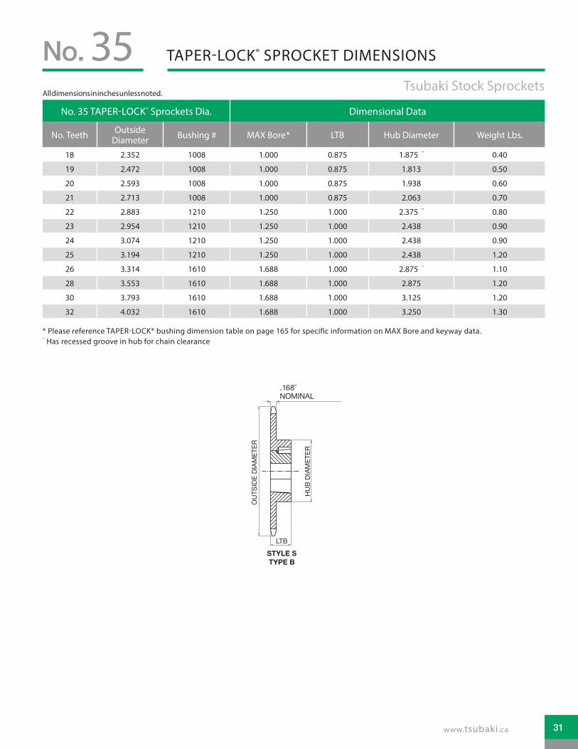
No.3/8˝ Pitch: TAPER-LOCK®35
HOW TO ORDERTSUBAKI STOCK SPROCKETS
Chain DataSize 35Pitch 3/8˝Inside Width 3/16˝Roller Diameter 0.200˝Nominal Tooth Width: 0.168˝
!! Alteration field only to be denoted if a deviation from standard is required. Please reference Alterations in engineering section, page 182.
Altered !! Chain Pitch in Inches Hub Type TAPER-LOCK® Number of Teeth
A: Alteration Required
35: 3/8˝ Pitch B: Hub Extension One Side
TAPER-LOCK® hub with set screws
18 21 24 26 3019 22 25 28 3220 23
How to Order Code: Example Model # for 35 Pitch TAPER-LOCK® Carbon Steel Sprockets
TAPER-LOCK® bushing is not included with the sprocket. They are to be ordered separately. Please refer to the table below for general guidelines. Speci�c details are found in the Bushing Section of this catalog beginning on page 164.
TAPER-LOCK® is a registered trademark of Rockwell Automation.
TAPER-LOCK® BushingsBushing # Bore Range
1008 0.500 - 1.000˝1210 0.500 - 1.250˝1610 0.500 - 1.688˝
A 35 B TL 18
30
TAPER-LOCK® SPROCKET DIMENSIONSNo. 35 Tsubaki Stock Sprockets
STYLE STYPE B
LTB
TOOTH (NOMINAL)
OU
TSID
EDI
AMET
ER
OU
TSID
EDI
AMET
ER
HU
BDI
AMET
ERLTB
STYLE STYPE B
PLATE THICKNESSTOOTH (NOMINAL)
OU
TSID
EDI
AMET
ER
HU
BDI
AMET
ER
HU
BDI
AMET
ER
STYLE ETYPE B
LTB
TOOTH (NOMINAL)
SINGLE “TAPER-LOCK” STYLE DOUBLE “TAPER-LOCK” STYLE
No. 35 TAPER-LOCK® Sprockets Dia. Dimensional Data
No. Teeth Outside Diameter Bushing # MAX Bore* LTB Hub Diameter Weight Lbs.
18 2.352 1008 1.000 0.875 1.875 ¨ 0.40
19 2.472 1008 1.000 0.875 1.813 0.50
20 2.593 1008 1.000 0.875 1.938 0.60
21 2.713 1008 1.000 0.875 2.063 0.70
22 2.883 1210 1.250 1.000 2.375 ¨ 0.80
23 2.954 1210 1.250 1.000 2.438 0.90
24 3.074 1210 1.250 1.000 2.438 0.90
25 3.194 1210 1.250 1.000 2.438 1.20
26 3.314 1610 1.688 1.000 2.875 ¨ 1.10
28 3.553 1610 1.688 1.000 2.875 1.20
30 3.793 1610 1.688 1.000 3.125 1.20
32 4.032 1610 1.688 1.000 3.250 1.30
* Please reference TAPER-LOCK® bushing dimension table on page 165 for specific information on MAX Bore and keyway data.¨ Has recessed groove in hub for chain clearance
.168NOMINAL
All dimensions in inches unless noted.
31www.tsubaki.ca

No.
How to Order Code: Example Model # for 35 Pitch QD® Carbon Steel Sprockets
35
HOW TO ORDERTSUBAKI STOCK SPROCKETS
Chain DataSize 35Pitch 3/8˝Inside Width 3/16˝Roller Diameter 0.200˝Nominal Tooth Width: 0.168˝3/8˝ Pitch: QD®
QD® bushing is not included with the sprocket. They are to be ordered separately. Please refer to the table below for general guidelines. Specific details are found in the Bushing Section of this catalog beginning on page 170.
QD® BushingsBushing # Bore Range
JA 0.500 - 1.250˝SH 0.500 - 1.688˝
Altered !! Chain Pitch in Inches QD® Hub Type Number of Teeth
A: Alteration Required
35: 3/8˝ Pitch
JA: QD® Hub 19 - 30 tooth sprocket
19 21 25 27 30
20 24 26 28
SH: QD® Hub 40 - 84 tooth sprocket
40 45 54 70 80
42 48 60 72 84
A 35 JA 24
!! Alteration field only to be denoted if a deviation from standard is required. Please reference Alterations in engineering section, page 182.
QD® is a registered trademark of, and is used under license agreement from Emerson Electric Co.32

QD® SPROCKET DIMENSIONSNo. 35 Tsubaki Stock Sprockets
No. 35 QD® Sprockets Dia. Dimensional Data
No. Teeth
Outside Diameter Bushing # MAX Bore* Hub
Diameter LTB X Y L F Weight Lbs.
19 2.472 JA 1.250 2.063 0.625 1.000 1.125 0.828 2.063 0.28
20 2.593 JA 1.250 2.063 0.625 1.125 1.125 0.828 2.063 0.32
21 2.713 JA 1.250 2.063 0.625 1.125 1.125 0.828 2.063 0.33
24 3.074 JA 1.250 2.063 0.625 1.125 1.125 0.828 2.063 0.40
25 3.194 JA 1.250 2.063 0.625 1.125 1.125 0.828 2.063 0.44
26 3.314 JA 1.250 2.063 0.625 1.125 1.125 0.828 2.063 0.45
27 3.434 JA 1.250 2.063 0.625 1.125 1.125 0.828 2.063 0.48
28 3.550 JA 1.250 2.063 0.625 1.125 1.125 0.828 2.063 0.52
30 3.793 JA 1.250 2.063 0.625 1.125 1.125 0.828 2.063 0.56
40 4.990 SH 1.688 2.688 0.563 1.438 1.438 1.078 2.688 1.18
42 5.230 SH 1.688 2.688 0.813 1.438 1.438 1.078 2.688 1.26
45 5.590 SH 1.688 2.688 0.813 1.438 1.438 1.078 2.688 1.40
48 5.946 SH 1.688 2.688 0.813 1.438 1.438 1.078 2.688 1.58
54 6.660 SH 1.688 2.688 0.813 1.438 1.438 1.078 2.688 1.88
60 7.380 SH 1.688 2.688 0.813 1.438 1.438 1.078 2.688 2.28
70 8.580 SH 1.688 2.688 0.813 1.438 1.438 1.078 2.688 2.94
72 8.810 SH 1.688 2.688 0.813 1.438 1.438 1.078 2.688 3.14
80 9.770 SH 1.688 2.688 0.813 1.438 1.438 1.078 2.688 3.68
84 10.250 SH 1.688 2.688 0.813 1.438 1.438 1.078 2.688 3.96
* Please reference QD® bushing dimension table on page 171 for specific information on MAX Bore and keyway data.
STYLE STYPE B
X
L
YLTB
OU
TSID
EDI
AMET
ER
HU
BDI
AMET
ER
Y
HU
BDI
AMET
ER
OU
TSID
EDI
AMET
ER
F F
STYLE ETYPE B
X
L
LTBTOOTH(NOMINAL)
TOOTH(NOMINAL)
.168NOMINAL
All dimensions in inches unless noted.
33www.tsubaki.ca

!! Alteration field only to be denoted if a deviation from standard is required. Please reference Alterations in engineering section, page 182.
A 41 A 36Altered !! Chain Pitch in Inches Hub Type Number of Teeth
A: Alteration Required
41: 1/2˝ Pitch
A: No Hub Extension
15 21 27 40 7016 22 28 42 7217 23 30 45 8018 24 32 48 8419 25 35 54 9620 26 36 60 112
B: Hub Extension One Side
8 16 24 36 729 17 25 40 80
10 18 26 42 8411 19 27 45 9612 20 28 48 11213 21 30 54
14 22 32 6015 23 35 70
Chain DataSize 41Pitch 1/2˝Inside Width 1/4˝Roller Diameter 0.306˝Nominal Tooth Width: 0.227˝
No.1/2˝ Pitch: PLAIN BORE
How to Order Code: Example Model # for 41 Pitch Plain Bore Carbon Steel Sprockets
41
HOW TO ORDER
LTBLTB
OU
TSID
EDI
AMET
ER
OU
TSID
EDI
AMET
ER
OU
TSID
EDI
AMET
ER
BORE
BORE
BORE
HU
BDI
AMET
ER
HU
BDI
AMET
ER
STYLE ETYPE B
STYLE STYPE B
TYPE A
TOOTH(NOMINAL)
TOOTH(NOMINAL)
TOOTH(NOMINAL)
.227NOMINAL
.227NOMINAL
.227NOMINAL
34

No. 41 Plain Bore Sprocket Diameters Type “A” Plain Bore Type “B” Plain Bore
No. Teeth
Outside Diameter
Pitch Diameter
Caliper Diameter
Plain Bore
Wt. Lbs.
Plain Bore
MAX Bore*
Hub Dia. LTB Style Wt.
Lbs.
8 1.510 1.307 1.002 NS NS 0.500 0.500 0.984 ¨ 0.875 S 0.19
9 1.670 1.462 1.134 NS NS 0.500 0.625 1.125 ¨ 0.875 S 0.20
10 1.840 1.618 1.312 NS NS 0.500 0.750 1.250 ¨ 0.875 S 0.27
11 2.000 1.775 1.451 NS NS 0.500 0.875 1.438 ¨ 0.875 S 0.35
12 2.170 1.932 1.626 NS NS 0.500 0.938 1.563 ¨ 0.875 S 0.44
13 2.330 2.089 1.768 NS NS 0.500 1.000 1.563 0.875 S 0.50
14 2.490 2.247 1.941 NS NS 0.500 1.250 1.750 0.875 S 0.57
15 2.650 2.405 2.086 0.625 0.28 0.500 1.313 1.906 0.875 S 0.72
16 2.810 2.563 2.257 0.625 0.34 0.625 1.375 2.063 0.875 S 0.91
17 2.980 2.721 2.403 0.625 0.36 0.625 1.500 2.234 1.000 S 1.09
18 3.140 2.879 2.573 0.625 0.44 0.625 1.625 2.375 1.000 S 1.25
19 3.300 3.038 2.722 0.625 0.46 0.625 1.750 2.469 1.000 S 1.49
20 3.460 3.355 2.890 0.625 0.52 0.625 1.875 2.750 1.000 S 1.64
21 3.620 3.513 3.040 0.625 0.60 0.625 1.875 2.875 1.000 E 1.81
22 3.780 3.672 3.207 0.625 0.66 0.625 2.000 3.000 1.000 E 1.93
23 3.940 3.672 3.357 0.625 0.72 0.625 2.250 3.188 1.000 E 2.25
24 4.100 3.831 3.525 0.625 0.82 0.625 2.250 3.250 1.000 E 2.33
25 4.200 3.989 3.675 0.625 0.88 0.625 2.250 3.250 1.000 E 2.46
26 4.418 4.148 3.842 0.625 0.94 0.625 2.250 3.250 1.000 E 2.50
27 4.580 4.307 3.994 0.625 1.00 0.625 2.250 3.250 1.000 E 2.56
28 4.740 4.465 4.159 0.625 1.08 0.625 2.250 3.250 1.000 E 2.64
30 5.060 4.783 4.477 0.594 1.20 0.625 2.250 3.250 1.000 E 2.80
32 5.380 5.101 4.794 0.594 1.44 0.625 2.250 3.250 1.000 E 2.96
35 5.860 5.578 5.266 0.594 1.70 0.625 2.375 3.250 1.000 E 3.12
36 6.020 5.737 5.431 0.594 1.84 0.625 2.375 3 .250 1.000 E 3.32
40 6.650 6.373 6.067 0.719 2.22 0.750 2.375 3.250 1.063 E 4.06
42 6.970 6.691 6.385 0.719 2.50 0.750 2.375 3.500 1.063 E 4.10
45 7.450 7.168 6.858 0.719 2.52 0.750 2.375 3.500 1.063 E 4.18
48 7.930 7.645 7.339 0.719 2.92 0.750 2.375 3.500 1.063 E 4.92
54 8.880 8.599 8.294 0.719 3.54 0.750 2.375 3.500 1.063 E 5.68
60 9.840 9.544 9.246 0.719 4.60 0.750 2.375 3.500 1.063 E 6.78
70 11.430 11.145 10.840 0.719 6.22 0.750 2.750 4.000 1.188 E 9.54
72 11.750 11.463 11.156 0.719 6.32 0.750 2.750 4.000 1.188 E 9.64
80 13.030 12.736 12.430 0.719 8.46 0.750 2.750 4.000 1.188 E 11.54
84 13.660 13.372 13.067 0.719 9.12 0.750 2.750 4.000 1.188 E 12.20
96 15.570 15.282 14.976 0.938 11.84 1.000 2.750 4.000 1.188 E 14.86
112 18.120 17.827 17.522 0.938 15.84 1.000 2.750 4.000 1.188 E 19.16
PLAIN BORE SPROCKET DIMENSIONSNo. 41 Tsubaki Stock Sprockets
* Dimensions shown allow for standard keyway with set screw at 90 degrees¨ Has recessed groove in hub for chain clearanceNS = Non Stock
All dimensions in inches unless noted.
35www.tsubaki.ca

** Hub bore size should be selected from dimensional table on the following page. Bore sizes that are not listed for a given number of sprocket teeth may be available per request as Altered.
41 B 36 F - 1BChain Pitch in Inches Hub Type Number of Teeth Finished Bore Hub Bore **
41: 1/2˝ Pitch
B: Hub Extension One Side
9 19 30 70
F: Sprocket bore supplied with keyway and two set screws
H: 1/2" (0.500")
10 20 32 72 J: 5/8" (0.625")
11 21 35 80 L: 3/4" (0.750")
12 22 36 94 1: 1" (1.000")
13 23 40 96 1B: 1-1/8" (1.125")
14 24 42 112 1C: 1-3/16" (1.188")
15 25 45 1D: 1-1/4" (1.250")
16 26 48 1F 1-3/8" (1.375")
17 27 54 1G: 1-7/16" (1.437")
18 28 60 1H: 1-1/2" (1.500")
No.1/2˝ Pitch: FINISHED BORE
How to Order Code: Example Model # for 41 Pitch Finished Bore Carbon Steel Sprockets
41
HOW TO ORDERTSUBAKI STOCK SPROCKETS
Chain DataSize 41Pitch 1/2˝Inside Width 1/4˝Roller Diameter 0.306˝Nominal Tooth Width: 0.227 ˝
OU
TSID
EDI
AMET
ER
BORE
HU
BDI
AMET
ER
STYLE ETYPE B
LTB
TOOTH (NOMINAL)
STYLE STYPE B
LTB
TOOTH (NOMINAL)
OU
TSID
EDI
AMET
ER
BORE
HU
BDI
AMET
ER
.227 NOMINAL .227 NOMINAL
36

No. 41 Finished Bore Sprocket Diameters
Type “F” Bored to Shaft Size (includes standard keyway and two set screws)
No. Teeth
Outside Diameter
Pitch Diameter
Caliper Diameter
.500
˝ **
.625
˝
.750
˝
1.00
0˝
1.12
5˝
1.18
88˝
1.25
0˝
1.37
5˝
1.43
8˝
1.50
0˝ Hub Style
Wt. Lbs.
9 1.670 1.462 1.134 • • S 0.20
10 1.840 1.618 1.312 • • S 0.27
11 2.000 1.775 1.451 • • • S 0.35
12 2.170 1.932 1.626 • • • S 0.44
13 2.330 2.089 1.768 • • • • S 0.50
14 2.490 2.247 1.941 • • • • S 0.57
15 2.650 2.405 2.086 • • • • S 0.72
16 2.810 2.563 2.257 • • • S 0.91
17 2.980 2.721 2.403 • • • S 1.09
18 3.140 2.879 2.573 • • • S 1.25
19 3.300 3.038 2.722 • • • S 1.49
20 3.460 3.196 2.890 • • • S 1.64
21 3.620 3.355 3.040 • • • E 1.81
22 3.780 3.513 3.207 • • • E 1.93
23 3.940 3.672 3.357 • • • E 2.25
24 4.100 3.831 3.525 • • • E 2.33
25 4.200 3.989 3.675 • • • E 2.46
26 4.418 4.148 3.842 • • • E 2.50
27 4.580 4.307 3.994 • • • E 2.56
28 4.740 4.465 4.159 • • • E 2.64
30 5.060 4.783 4.477 • • • E 2.80
32 5.380 5.101 4.794 • • • E 2.96
35 5.860 5.578 5.266 • • • E 3.12
36 6.020 5.737 5.431 • • • E 3.32
40 6.650 6.373 6.067 • • • • • • • • E 4.06
42 6.970 6.691 6.385 • • • • • • • • E 4.10
45 7.450 7.168 6.858 • • • • • • • • E 4.18
48 7.930 7.645 7.339 • • • • • • • • E 4.92
54 8.880 8.599 8.294 • • • • • • • • E 5.68
60 9.840 9.544 9.246 • • • • • • • • E 6.78
70 11.430 11.145 10.840 • • • • • • • • E 9.54
72 11.750 11.463 11.156 • • • • • • • • E 9.64
80 13.030 12.736 12.430 • • • • • • • • E 11.54
84 13.660 13.372 13.067 • • • • • • • • E 12.20
96 15.570 15.282 14.976 • • • • • • • E 14.86
112 18.120 17.827 17.522 • • • • • • • E 19.16
FINISHED BORE SPROCKET DIMENSIONSNo. 41 Tsubaki Stock Sprockets
• Denotes stocking item ** Furnished without keyway
All dimensions in inches unless noted.
37www.tsubaki.ca

!! Alteration field only to be denoted if a deviation from standard is required. Please reference Alterations in engineering section, page 182.
A 41 B TL 18Altered !! Chain Pitch in Inches Hub Type TAPER-LOCK® Number of Teeth
A: Alteration Required
41: 1/2˝ Pitch B: Hub Extension One Side
TAPER-LOCK® hub with set screws
14 20 26 40 7215 21 28 45 8016 22 30 48 9617 23 32 5418 24 35 6019 25 36 70
No.1/2˝ Pitch: TAPER-LOCK®
How to Order Code: Example Model # for 41 Pitch TAPER-LOCK® Carbon Steel Sprockets
41
HOW TO ORDERTSUBAKI STOCK SPROCKETS
TAPER-LOCK® BushingsBushing # Bore Range
1008 0.500 - 1.000˝1210 0.500 - 1.250˝1610 0.500 - 1.688˝
Chain DataSize 41Pitch 1/2˝Inside Width 1/4˝Roller Diameter 0.306˝Nominal Tooth Width: 0.227˝
TAPER-LOCK® bushing is not included with the sprocket. They are to be ordered separately. Please refer to the table below for general guidelines. Speci�c details are found in the Bushing Section of this catalog beginning on page 164.
TAPER-LOCK® is a registered trademark of Rockwell Automation.38

No. 41 TAPER-LOCK® Sprockets Dia. Dimensional Data
No. Teeth Outside Dia. Bushing # MAX Bore* LTB Hub Diameter Hub Style Weight Lbs.
14 2.490 1008 1.000 0.875 1.875 ¨ S 0.40
15 2.650 1008 1.000 0.875 1.875 S 0.50
16 2.810 1008 1.000 0.875 2.000 S 0.60
17 2.970 1210 1.250 1.000 2.375 ¨ S 0.70
18 3.140 1210 1.250 1.000 2.375 S 0.90
19 3.300 1210 1.250 1.000 2.500 S 1.10
20 3.460 1610 1.688 1.000 2.875 ¨ S 1.10
21 3.620 1610 1.688 1.000 3.000 ¨ S 1.20
22 3.780 1610 1.688 1.000 3.000 S 1.30
23 3.940 1610 1.688 1.000 3.000 S 1.40
24 4.100 1610 1.688 1.000 3.000 S 1.40
25 4.200 1610 1.688 1.000 3.000 S 1.50
26 4.420 1610 1.688 1.000 3.000 S 1.50
28 4.740 1610 1.688 1.000 3.000 E 1.70
30 5.060 1610 1.688 1.000 3.000 E 1.80
32 5.380 1610 1.688 1.000 3.000 E 1.90
35 5.860 1610 1.688 1.000 3.000 E 2.30
36 6.020 1610 1.688 1.000 3.000 E 2.40
40 6.650 1610 1.688 1.000 3.000 E 2.70
45 7.450 1610 1.688 1.000 3.000 E 3.50
48 7.930 1610 1.688 1.000 3.000 E 4.10
54 8.880 1610 1.688 1.000 3.000 E 4.90
60 9.840 1610 1.688 1.000 3.000 E 5.70
70 11.430 1610 1.688 1.000 3.000 E 7.40
72 11.750 1610 1.688 1.000 3.000 E 8.20
80 13.030 1610 1.688 1.000 3.000 E 9.60
96 15.570 1610 1.688 1.000 3.000 E 13.10
TAPER-LOCK® SPROCKET DIMENSIONSNo. 41 Tsubaki Stock Sprockets
STYLE STYPE B
LTB
TOOTH (NOMINAL)
OU
TSID
EDI
AMET
ER
OU
TSID
EDI
AMET
ER
HU
BDI
AMET
ER
LTBSTYLE STYPE B
PLATE THICKNESSTOOTH (NOMINAL)
OU
TSID
EDI
AMET
ER
HU
BDI
AMET
ER
HU
BDI
AMET
ER
STYLE ETYPE B
LTB
TOOTH (NOMINAL)
SINGLE “TAPER-LOCK” STYLE DOUBLE “TAPER-LOCK” STYLE
.227 NOMINAL .227 NOMINAL
* Please reference TAPER-LOCK® bushing dimension table on page 165 for specific information on MAX Bore and keyway data.¨ Has recessed groove in hub for chain clearance
All dimensions in inches unless noted.
39www.tsubaki.ca

No.1/2˝ Pitch: QD®
How to Order Code: Example Model # for 41 Pitch QD® Carbon Steel Sprockets
41
!! Alteration field only to be denoted if a deviation from standard is required. Please reference Alterations in engineering section, page 182.
A 41 JA 19Altered !! Chain Pitch in Inches QD® Hub Type Number of Teeth
A: Alteration Required
41: 1/2˝ Pitch
JA: QD® Hub 15 - 19 tooth sprocket
15 17 19
16 18
SH: QD® Hub 20 - 35 tooth sprocket
20 23 26 30
21 24 27 32
22 25 28 35
SDS: QD® Hub 36 - 60 tooth sprocket
36 42 48 60
40 45 54
SK: QD® Hub 70 - 112 tooth sprocket
70 80 96
72 84 112
HOW TO ORDERTSUBAKI STOCK SPROCKETS
Chain DataSize 41Pitch 1/2˝Inside Width 1/4˝Roller Diameter 0.306˝Nominal Tooth Width: 0.227˝
QD® bushing is not included with the sprocket. They are to be ordered separately. Please refer to the table below for general guidelines. Specific details are found in the Bushing Section of this catalog beginning on page 170.
QD® BushingsBushing # Bore Range
JA 0.500 - 1.250˝SH 0.500 - 1.688˝
SDS 0.500 - 2.000˝SK 0.500 - 2.625˝
STYLE STYPE B
X
L
YLTB
OU
TSID
EDI
AMET
ER
HU
BDI
AMET
ER
Y
HU
BDI
AMET
ER
OU
TSID
EDI
AMET
ER
F F
STYLE ETYPE B
X
L
LTBTOOTH(NOMINAL)
TOOTH(NOMINAL).227NOMINAL.227
NOMINAL
QD® is a registered trademark of, and is used under license agreement from Emerson Electric Co.40

No. 41 QD® Sprockets Dia. Dimensional Data
No. Teeth
Outside Diameter Bushing # MAX
Bore* Hub
Diameter LTB X Y L F Hub Style
Weight Lbs.
15 2.650 JA 1.250 2.063 0.625 1.125 1.125 0.766 2.063 S 0.32
16 2.810 JA 1.250 2.063 0.625 1.125 1.125 0.766 2.063 S 0.40
17 2.970 JA 1.250 2.063 0.625 1.125 1.125 0.766 2.063 S 0.50
18 3.140 JA 1.250 2.063 0.625 1.125 1.125 0.766 2.063 S 0.60
19 3.300 JA 1.250 2.063 0.625 1.125 1.125 0.766 2.063 S 0.68
20 3.460 SH 1.688 2.688 0.813 1.438 1.438 1.031 2.688 S 0.78
21 3.620 SH 1.688 2.688 0.813 1.438 1.438 1.031 2.688 S 0.82
22 3.780 SH 1.688 2.688 0.813 1.438 1.438 1.031 2.688 S 1.06
23 3.940 SH 1.688 2.688 0.813 1.438 1.438 1.031 2.688 S 1.14
24 4.100 SH 1.688 2.688 0.813 1.438 1.438 1.031 2.688 S 1.16
25 4.200 SH 1.688 2.688 0.813 1.438 1.438 1.031 2.688 S 1.22
26 4.420 SH 1.688 2.688 0.813 1.438 1.438 1.031 2.688 S 1.26
27 4.580 SH 1.688 2.688 0.813 1.438 1.438 1.031 2.688 S 1.40
28 4.740 SH 1.688 2.688 0.813 1.438 1.438 1.031 2.688 S 1.54
30 5.060 SH 1.688 2.688 0.813 1.438 1.438 1.031 2.688 S 1.58
32 5.380 SH 1.688 2.688 0.813 1.438 1.438 1.031 2.688 S 1.68
35 5.860 SH 1.688 2.688 0.813 1.438 1.438 1.031 2.688 S 2.47
36 6.020 SDS 2.000 3.188 0.750 1.500 1.500 1.094 3.188 E 1.92
40 6.650 SDS 2.000 3.188 0.750 1.500 1.500 1.094 3.188 E 2.32
42 6.970 SDS 2.000 3.188 0.750 1.500 1.500 1.094 3.188 E 2.44
45 7.450 SDS 2.000 3.188 0.750 1.500 1.500 1.094 3.188 E 2.76
48 7.930 SDS 2.000 3.188 0.750 1.500 1.500 1.094 3.188 E 3.36
54 8.880 SDS 2.000 3.188 0.750 1.500 1.500 1.094 3.188 E 3.98
60 9.840 SDS 2.000 3.188 0.750 1.500 1.500 1.094 3.188 E 5.54
70 11.430 SK 2.625 3.875 1.250 2.125 2.125 1.641 3.875 E 7.42
72 11.750 SK 2.625 3.875 1.250 2.125 2.125 1.641 3.875 E 8.02
80 13.030 SK 2.625 3.875 1.250 2.125 2.125 1.641 3.875 E 9.64
84 13.660 SK 2.625 3.875 1.250 2.125 2.125 1.641 3.875 E 10.40
96 15.570 SK 2.625 3.875 1.250 2.125 2.125 1.641 3.875 E 12.82
112 18.120 SK 2.625 3.875 1.250 2.125 2.125 1.641 3.875 E 17.28
QD® SPROCKET DIMENSIONSNo. 41 Tsubaki Stock Sprockets
* Please reference QD® bushing dimension table on page 171 for specific information on MAX Bore and keyway data.
All dimensions in inches unless noted.
41www.tsubaki.ca

!! Alteration �eld only to be denoted if a deviation from standard is required. Please reference Alterations in engineering section, page 182.
A 40 A 96
Chain DataSize 40Pitch 1/2˝Inside Width 5/16˝Roller Diameter 0.312 ˝Nominal Tooth Width: 0.284˝
How to Order Code: Example Model # for 40 Pitch Plain Bore Carbon Steel Sprockets
HOW TO ORDERTSUBAKI STOCK SPROCKETS
No.1/2˝ Pitch: PLAIN BORE40
Altered !! Chain Pitch in Inches Hub Type Number of Teeth
A: Alteration Required
40: 1/2˝ Pitch
A: No Hub Extension
12 23 34 45 5613 24 35 46 5714 25 36 47 5815 26 37 48 5916 27 38 49 6017 28 39 50 7018 29 40 51 7219 30 41 52 8020 31 42 53 8421 32 43 54 9622 33 44 55 112
B: Hub Extension One Side
8 20 32 44 569 21 33 45 57
10 22 34 46 5811 23 35 47 5912 24 36 48 6013 25 37 49 7014 26 38 50 7215 27 39 51 8016 28 40 52 8417 29 41 53 9618 30 42 54 11219 31 43 55
LTBLTB
OU
TSID
EDI
AMET
ER
OU
TSID
EDI
AMET
ER
OU
TSID
EDI
AMET
ER
BORE
BORE
BORE
HU
BDI
AMET
ER
HU
BDI
AMET
ER
STYLE ETYPE B
STYLE STYPE B
TYPE A
TOOTH(NOMINAL)
TOOTH(NOMINAL)
TOOTH(NOMINAL).284NOMINAL
.284NOMINAL
.284NOMINAL
42

PLAIN BORE SPROCKET DIMENSIONSNo. 40 Tsubaki Stock Sprockets
No. 40 Plain Bore Sprocket Dia. Type “A” Plain Bore Type “B” Plain Bore
No. Teeth
Outside Dia.
Pitch Dia.
Caliper Dia.
Plain Bore
Wt. Lbs.
Plain Bore
MAX Bore *
Hub Dia. LTB Hub
StyleWt. Lbs.
8 1.510 1.307 0.995 NS NS 0.500 0.500 0.984 ¨ 0.875 S 0.189 1.670 1.462 1.127 NS NS 0.500 0.563 1.063 ¨ 0.875 S 0.20
10 1.840 1.618 1.305 NS NS 0.500 0.750 1.250 ¨ 0.875 S 0.2711 2.000 1.775 1.444 NS NS 0.500 0.875 1.375 ¨ 0.875 S 0.3512 2.170 1.932 1.620 0.500 0.18 0.500 1.000 1.563 ¨ 0.875 S 0.4513 2.330 2.089 1.761 0.500 0.22 0.500 1.063 1.563 0.875 S 0.5014 2.490 2.247 1.934 0.500 0.25 0.500 1.125 1.688 0.875 S 0.5915 2.650 2.405 2.079 0.625 0.30 0.500 1.250 1.813 0.875 S 0.7016 2.810 2.563 2.250 0.625 0.34 0.625 1.375 2.000 0.875 S 0.7917 2.980 2.721 2.397 0.625 0.36 0.625 1.438 2.125 1.000 S 1.0418 3.140 2.879 2.567 0.625 0.44 0.625 1.500 2.313 1.000 S 1.2219 3.300 3.038 2.715 0.625 0.46 0.625 1.750 2.500 1.000 S 1.4320 3.460 3.196 2.883 0.625 0.56 0.625 1.875 2.625 1.000 S 1.5621 3.620 3.355 3.033 0.625 0.58 0.625 1.875 2.750 1.000 S 1.7322 3.780 3.513 3.201 0.625 0.66 0.625 1.875 2.875 1.000 E 1.9623 3.940 3.672 3.351 0.625 0.72 0.625 2.000 3.000 1.000 E 2.1324 4.100 3.831 3.518 0.625 0.82 0.625 2.250 3.250 1.000 E 2.4125 4.260 3.989 3.669 0.625 0.88 0.625 2.250 3.250 1.000 E 2.5426 4.420 4.148 3.835 0.625 0.94 0.625 2.250 3.250 1.000 E 2.5827 4.580 4.307 3.987 0.625 0.98 0.625 2.250 3.250 1.000 E 2.6628 4.740 4.465 4.153 0.625 1.10 0.625 2.250 3.250 1.000 E 2.7329 4.900 4.625 4.305 0.594 1.22 0.625 2.250 3.250 1.000 E 2.8030 5.060 4.783 4.471 0.594 1.25 0.625 2.250 3.250 1.000 E 2.9831 5.220 4.942 4.623 0.594 1.40 0.625 2.250 3.250 1.000 E 3.1032 5.380 5.101 4.788 0.594 1.48 0.625 2.250 3.250 1.000 E 3.1633 5.540 5.260 4.941 0.594 1.56 0.625 2.250 3.250 1.000 E 3.2234 5.700 5.419 5.107 0.594 1.64 0.625 2.250 3.250 1.000 E 3.3035 5.860 5.578 5.260 0.594 1.70 0.625 2.250 3.250 1.000 E 3.4636 6.020 5.737 5.425 0.594 1.84 0.625 2.250 3.250 1.000 E 3.5837 6.180 5.896 5.578 0.594 1.92 0.625 2.250 3.250 1.000 E 3.6238 6.330 6.055 5.742 0.594 2.00 0.625 2.250 3.250 1.000 E 3.7039 6.490 6.214 5.896 0.594 2.02 0.625 2.250 3.250 1.000 E 3.7640 6.660 6.373 6.061 0.719 2.22 0.750 2.375 3.500 1.125 E 4.6941 6.810 6.532 6.214 0.719 2.42 0.750 2.375 3.500 1.125 E 4.7642 6.970 6.691 6.379 0.719 2.50 0.750 2.375 3.500 1.125 E 4.8243 7.130 6.850 6.532 0.719 2.80 0.750 2.375 3.500 1.125 E 5.1244 7.290 7.009 6.696 0.719 2.85 0.750 2.375 3.500 1.125 E 5.1545 7.450 7.168 6.851 0.719 3.15 0.750 2.375 3.500 1.125 E 5.3046 7.610 7.327 7.014 0.719 3.25 0.750 2.375 3.500 1.125 E 5.5747 7.770 7.486 7.169 0.719 3.32 0.750 2.375 3.500 1.125 E 5.4448 7.930 7.645 7.332 0.719 3.22 0.750 2.375 3.500 1 .125 E 5.8449 8.090 7.804 7.487 0.719 3.44 0.750 2.375 3.500 1.125 E 5.9050 8.250 7.963 7.650 0.719 3.62 0.750 2.375 3.500 1.125 E 5.9551 8.410 8.124 7.805 0.719 3.94 0.750 2.375 3.500 1.125 E 6.0852 8.570 8.281 7.968 0.719 4.08 0.750 2.375 3.500 1.125 E 6.2853 8.730 8.440 8.124 0.719 4.24 0.750 2.375 3.500 1.125 E 6.3354 8.890 8.599 8.286 0.719 4.44 0.750 2.375 3.500 1.125 E 6.4255 9.040 8.758 8.442 0.719 4.54 0.750 2.375 3.500 1.125 E 6.4656 9.200 8.917 8.605 0.719 4.84 0.750 2.375 3.500 1.125 E 6.8957 9.360 9.077 8.760 0.719 5.00 0.750 2.375 3.500 1.125 E 7.0258 9.520 9.235 8.924 0.719 5.12 0.750 2.375 3.500 1.125 E 7.3559 9.680 9.395 9.078 0.719 5.30 0.750 2.375 3.500 1.125 E 7.4560 9.840 9.554 9.241 0.719 5.48 0.750 2.375 3.500 1.125 E 7.8670 11.430 11.145 10.832 0.719 7.24 0.750 2.750 4.000 1.250 E 11.0072 11.750 11.463 11.151 0.719 7.74 0.750 2.750 4.000 1.250 E 11.5080 13.030 12.736 12.423 0.719 10.20 0.750 2.750 4.000 1.250 E 13.4084 13.660 13.372 13.059 0.719 10.07 0.750 2.750 4.000 1.250 E 14.0496 15.570 15.282 14.969 0.938 12.15 1.000 2.750 4.000 1.250 E 17.56
112 18.120 17.827 17.515 0.938 20.00 1.000 2.750 4.000 1.250 E 22.56
* Dimensions shown allow for standard keyway with set screw at 90 degrees¨ Has recessed groove in hub for chain clearanceNS = Non Stock
All dimensions in inches unless noted.
43www.tsubaki.ca
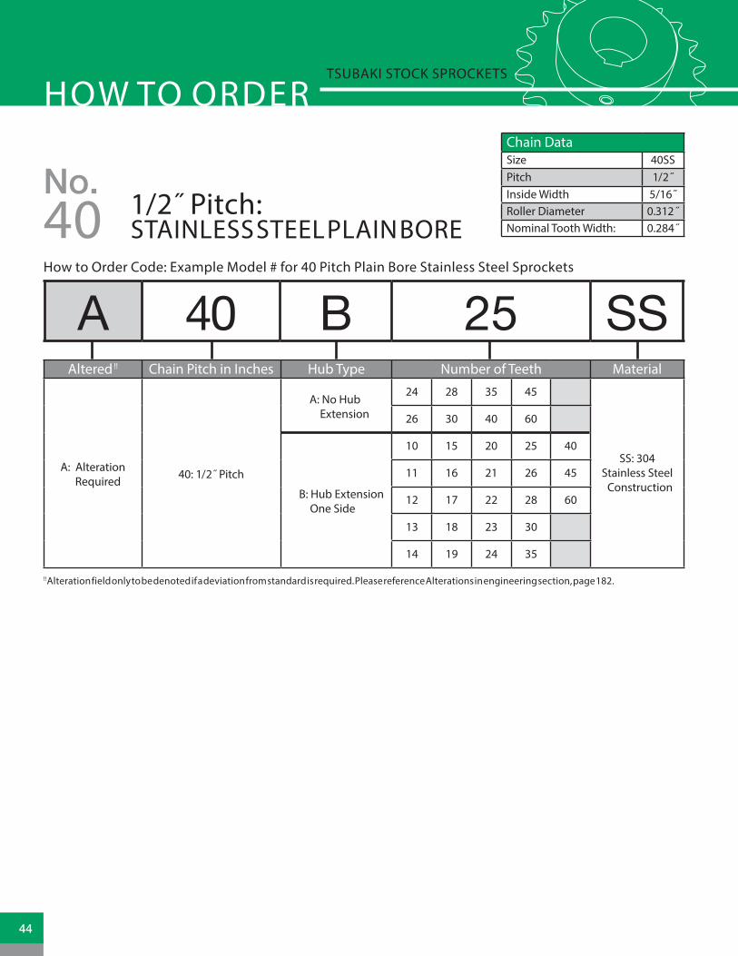
How to Order Code: Example Model # for 40 Pitch Plain Bore Stainless Steel Sprockets
A 40 B 25 SS
HOW TO ORDERTSUBAKI STOCK SPROCKETS
Chain DataSize 40SSPitch 1/2˝Inside Width 5/16˝Roller Diameter 0.312 ˝Nominal Tooth Width: 0.284˝
No.1/2˝ Pitch: STAINLESS STEEL PLAIN BORE40
!! Alteration field only to be denoted if a deviation from standard is required. Please reference Alterations in engineering section, page 182.
Altered !! Chain Pitch in Inches Hub Type Number of Teeth Material
A: Alteration Required
40: 1/2˝ Pitch
A: No Hub Extension
24 28 35 45
SS: 304 Stainless Steel Construction
26 30 40 60
B: Hub Extension One Side
10 15 20 25 40
11 16 21 26 45
12 17 22 28 60
13 18 23 30
14 19 24 35
44

No. 40 Stainless Steel Sprocket Diameters Type “A” Plain Bore Type “B” Plain Bore
No. Teeth
Outside Diameter
Pitch Diameter
Caliper Diameter
Plain Bore
Wt. Lbs.
Plain Bore
MAX Bore *
Hub Dia. LTB Hub
StyleWt. Lbs.
10 1.840 1.618 1.305 N/A N/A 0.500 0.750 1.250 ̈ 0.875 S 0.28
11 2.000 1.775 1.444 N/A N/A 0.500 0.813 1.375 ̈ 0.875 S 0.36
12 2.170 1.932 1.620 N/A N/A 0.500 0.938 1.563 ̈ 0.875 S 0.44
13 2.330 2.089 1.761 N/A N/A 0.500 1.063 1.563 0.875 S 0.50
14 2.490 2.247 1.934 N/A N/A 0.500 1.125 1.688 0.875 S 0.60
15 2.650 2.405 2.079 N/A N/A 0.500 1.250 1.813 0.875 S 0.68
16 2.810 2.563 2.250 N/A N/A 0.625 1.375 2.000 0.875 S 0.82
17 2.980 2.721 2.397 N/A N/A 0.625 1.438 2.125 1.000 S 1.06
18 3.140 2.879 2.567 N/A N/A 0.625 1.500 2.313 1.000 S 1.24
19 3.300 3.038 2.715 N/A N/A 0.625 1.750 2.500 1.000 S 1.42
20 3.460 3.196 2.883 N/A N/A 0.625 1.875 2.625 1.000 S 1.60
21 3.620 3.355 3.033 N/A N/A 0.625 1.875 2.750 1.000 S 1.68
22 3.780 3.513 3.201 N/A N/A 0.625 1.875 2.875 1.000 S 1.81
23 3.940 3.672 3.351 N/A N/A 0.625 2.000 3.000 1.000 S 2.18
24 4.100 3.831 3.518 0.594 0.80 0.625 2.250 3.250 1.000 D 2.20
25 4.260 3.989 3.669 N/A N/A 0.625 2.250 3.250 1.000 D 2.39
26 4.420 4.148 3.835 0.594 1.31 0.625 2.250 3.250 1.000 D 2.40
28 4.740 4.465 4.153 0.594 1.35 0.625 2.250 3.250 1.000 D 2.75
30 5.060 4.783 4.471 0.594 1.39 0.625 2.250 3.250 1.000 D 2.88
35 5.860 5.578 5.260 0.594 1.92 0.625 2.250 3.250 1.000 D 3.32
40 6.650 6.373 6.061 0.719 2.36 0.750 2.375 3.500 1.000 D 4.28
45 7.450 7.168 6.851 0.719 3.13 0.750 2.375 3.500 1.000 D 4.68
60 9.840 9.554 9.241 0.719 5.50 0.750 2.375 3.500 1.000 D 7.00
STAINLESS STEEL SPROCKET DIMENSIONSNo. 40 Tsubaki Stock Sprockets
* Dimension depicted allows for standard keyway with set screw at 90 degrees¨ Has recessed groove in hub for chain clearanceN/A = Not Available
LTBLTB
OU
TSID
EDI
AMET
ER
OU
TSID
EDI
AMET
ER
OU
TSID
EDI
AMET
ER
BORE
BORE
BORE
HU
BDI
AMET
ER
HU
BDI
AMET
ER
STYLE ETYPE B
STYLE STYPE B
TYPE A
TOOTH(NOMINAL)
TOOTH(NOMINAL)
TOOTH(NOMINAL)
LTB
OU
TSID
EDI
AMET
ER
BORE
HU
BDI
AMET
ER
STYLE DTYPE B
TOOTH(NOMINAL)
.284NOMINAL
.284NOMINAL
LTBLTB
OU
TSID
EDI
AMET
ER
OU
TSID
EDI
AMET
ER
OU
TSID
EDI
AMET
ER
BORE
BORE
BORE
HU
BDI
AMET
ER
HU
BDI
AMET
ER
STYLE ETYPE B
STYLE STYPE B
TYPE A
TOOTH(NOMINAL)
TOOTH(NOMINAL)
TOOTH(NOMINAL)
LTB
OU
TSID
EDI
AMET
ER
BORE
HU
BDI
AMET
ER
STYLE DTYPE B
TOOTH(NOMINAL)
.284NOMINAL
All dimensions in inches unless noted.
45www.tsubaki.ca

How to Order Code: Example Model # for 40 Pitch Finished Bore Carbon Steel Sprockets
40 B 60 F - 1B
HOW TO ORDERTSUBAKI STOCK SPROCKETS
Chain DataSize 40Pitch 1/2˝Inside Width 5/16˝Roller Diameter 0.312 ˝Nominal Tooth Width: 0.284˝
No.1/2˝ Pitch: FINISHED BORE40
** Hub bore size should be selected from dimensional table on the following page. Bore sizes that are not listed for a given number of sprocket teeth may be available per request as Altered.
Chain Pitch in Inches Hub Type Number of Teeth Finished Bore Hub Bore **
40: 1/2˝ Pitch
B: Hub Extension One Side
9 21 33 45 57
F: Hub Extension Machined with keyway and two set screws
H: 1/2" (0.500")
10 22 34 46 58 J: 5/8" (0.625")
11 23 35 47 59 L: 3/4" (0.750")
12 24 36 48 60 P 7/8" (0.875")
13 25 37 49 70 1: 1" (1.000")
14 26 38 50 72 1B: 1-1/8" (1.125")
15 27 39 51 80 1C: 1-3/16" (1.188")
16 28 40 52 84 1D: 1-1/4" (1.250")
17 29 41 53 96 1F: 1-3/8" (1.375")
18 30 42 54 112 1G: 1-7/16" (1.437")
19 31 43 55 1H: 1-1/2" (1.500")
20 32 44 56
OU
TSID
EDI
AMET
ER
BORE
HU
BDI
AMET
ER
STYLE ETYPE B
LTB
TOOTH (NOMINAL)
STYLE STYPE B
LTB
TOOTH (NOMINAL)
OU
TSID
EDI
AMET
ER
BORE
HU
BDI
AMET
ER
.284 NOMINAL .284 NOMINAL
46

No. 40 Sprocket Diameters Type “F” Bored to Shaft Size (includes standard keyway and two set screws)
No. Teeth Outside Dia. Pitch Dia. Caliper Dia.
.500
˝ **
.625
˝
.750
˝
.875
˝
1.00
0˝
1.12
5˝
1.18
7˝
1.25
0˝
1.37
5˝
1.43
8˝
1.50
0˝ Hub Style
Wt. Lbs.
9 1.674 1.462 1.127 • • S 0.2010 1.839 1.618 1.305 • • • S 0.2711 2.003 1.775 1.444 • • • • S 0.3512 2.166 1.932 1.620 • • • • • S 0.4513 2.328 2.089 1.761 • • • • • S 0.5014 2.490 2.247 1.934 • • • • • S 0.5915 2.652 2.405 2.079 • • • • • • • ¢ • ¢ S 0.7016 2.814 2.563 2.250 • • • • • • • S 0.7917 2.974 2.721 2.397 • • • • • • • S 1.0418 3.136 2.879 2.567 • • • • • • • • • ¢ • ¢ S 1.2219 3.292 3.038 2.715 • • • • • • • • • • S 1.4320 3.457 3.196 2.883 • • • • • • • • • • S 1.5621 3.618 3.355 3.033 • • • • • • • • • • S 1.7322 3.778 3.513 3.201 • • • • • • • • • • E 1.9623 3.938 3.672 3.351 • • • • • • • • • • E 2.1324 4.098 3.831 3.518 • • • • • • • • • • E 2.4125 4.258 3.989 3.669 • • • • • • • • • E 2.5426 4.418 4.148 3.835 • • • • • • • • • E 2.5827 4.578 4.307 3.987 • • • • • • • • • E 2.6628 4.738 4.465 4.153 • • • • • • • • • E 2.7329 4.900 4.625 4.305 • • • • • • • • • E 2.8030 5.057 4.783 4.471 • • • • • • • • • E 2.9831 5.220 4.942 4.623 • • • • • • • • • E 3.1032 5.376 5.101 4.788 • • • • • • • • • E 3.1633 5.540 5.260 4.941 • • • • • • • • • E 3.2234 5.696 5.419 5.107 • • • • • • • • • E 3.3035 5.856 5.578 5.260 • • • • • • • • • E 3.4636 6.015 5.737 5.425 • • • • • • • • • E 3.5837 6.170 5.896 5.578 • • • • • • • • • E 3.6238 6.334 6.055 5.742 • • • • • • • • • E 3.7039 6.490 6.214 5.896 • • • • • • • • • E 3.7640 6.653 6.373 6.061 • • • • • • • • E 4.6941 6.810 6.532 6.214 • • • • • • • • E 4.7642 6.972 6.691 6.379 • • • • • • • • E 4.8243 7.130 6.850 6.532 • • • • • • • • E 5.1244 7.290 7.009 6.696 • • • • • • • • E 5.1545 7.450 7.168 6.851 • • • • • • • • E 5.3046 7.610 7.327 7.014 • • • • • • • • E 5.5747 7.770 7.486 7.169 • • • • • • • • E 5.4448 7.930 7.645 7.332 • • • • • • • • E 5.8449 8.090 7.804 7.487 • • • • • • • • E 5.9050 8.250 7.963 7.650 • • • • • • • • E 5.9551 8.410 8.122 7.805 • • • • • • • • E 6.0852 8.570 8.281 7.968 • • • • • • • • E 6.2853 8.730 8.440 8.124 • • • • • • • • E 6.3354 8.890 8.599 8.826 • • • • • • • • E 6.4255 9.040 8.758 8.442 • • • • • • • • E 6.4656 9.200 8.917 8.605 • • • • • • • • E 6.8957 9.360 9.077 8.760 • • • • • • • • E 7.0258 9.520 9.235 8.924 • • • • • • • • E 7.3559 9.680 9.395 9.078 • • • • • • • • E 7.4560 9.840 9.554 9.241 • • • • • • • • E 7.8670 11.430 11.145 10.832 • • • • • • • • E 11.0072 11.750 11.463 11.151 • • • • • • • • E 11.5080 13.030 12.736 12.423 • • • • • • • • E 13.4084 13.660 13.372 13.059 • • • • • • • • E 14.0496 15.570 15.282 14.969 • • • • • • E 17.56
112 18.120 17.827 17.515 • • • • • • E 22.56
FINISHED BORE SPROCKET DIMENSIONSNo. 40 Tsubaki Stock Sprockets
• Denotes stocked item ¢ Indicates ser screw at 90 degrees and 180 degrees from keyway** Furnished without keyway
All dimensions in inches unless noted.
47www.tsubaki.ca

How to Order Code: Example Model # for 40 Pitch Multi-Strand Carbon Steel Sprockets
A D 40 B 18
HOW TO ORDERTSUBAKI STOCK SPROCKETS
Chain DataSize 40-2, 40-3Pitch 1/2˝Inside Width 5/16˝Roller Diameter 0.312 ˝Nominal Tooth Width: 0.275˝
No.1/2˝ Pitch: MULTI-STRAND40
Altered !! Multi Chain Pitch in Inches Hub Type Number of Teeth
A: Alteration Required
D: Double Strand
40: 1/2˝ PitchB: Hub Extension One Side
Double Strand11 17 23 36 5412 18 24 40 6013 19 25 4214 20 26 45
15 21 30 48
16 22 35 52
T: Triple Strand
Triple Strand
11 15 19 23 30
12 16 20 24 35
13 17 21 25 36
14 18 22 26
!! Alteration field only to be denoted if a deviation from standard is required. Please reference Alterations in engineering section, page 182.
OU
TSID
EDI
AMET
ER
OU
TSID
EDI
AMET
ER
BORE
OU
TSID
EDI
AMET
ERBO
RE
BORE
HU
BDI
AMET
ER
HU
BDI
AMET
ER
HU
BDI
AMET
ER
OU
TSID
EDI
AMET
ERBO
RE
HU
BDI
AMET
ER
STYLE STYPE B
STYLE STYPE B
STYLE DTYPE B
DOUBLE STRAND DOUBLE STRAND TRIPLE STRAND TRIPLE STRAND
LTB
STYLE DTYPE B
LTB LTB LTB
TOOTH (NOMINAL)PLATE THICKNESS
TOOTH (NOMINAL)PLATE THICKNESS
OU
TSID
EDI
AMET
ER
OU
TSID
EDI
AMET
ER
BORE
OU
TSID
EDI
AMET
ERBO
RE
BORE
HU
BDI
AMET
ER
HU
BDI
AMET
ER
HU
BDI
AMET
ER
OU
TSID
EDI
AMET
ERBO
RE
HU
BDI
AMET
ER
STYLE STYPE B
STYLE STYPE B
STYLE DTYPE B
DOUBLE STRAND DOUBLE STRAND TRIPLE STRAND TRIPLE STRAND
LTB
STYLE DTYPE B
LTB LTB LTB
TOOTH (NOMINAL)PLATE THICKNESS
TOOTH (NOMINAL)PLATE THICKNESSPLATE T ICKNESS 0.841 PLATE T ICKNESS 1.40
.275 NOMINAL .275 NOMINAL
48

No. 40 Multi Strand Sprocket Dia. Dimensional Data: Double Strand Sprockets
No. Teeth Outside Dia. Plain Bore Hub Diameter LTB MAX Bore + Hub Style Weight Lbs. 11 2.003 0.500 1.438 ̈ 1.500 0.750 S 0.6212 2.166 0.500 1.563 ̈ 1.500 0.938 S 0.7613 2.328 0.500 1.500 1.500 1.000 S 0.8614 2.490 0.500 1.688 1.500 1.125 S 1.0815 2.652 0.500 1.813 1.500 1.250 S 1.2416 2.814 0.625 2.000 1.500 1.375 S 1.4217 2.974 0.625 2.125 1.500 1.438 S 1.6418 3.136 0.625 2.313 1.500 1.500 S 1.9219 3.292 0.625 2.500 1.500 1.750 S 2.2220 3.457 0.625 2.625 1.625 1.875 S 2.6421 3.618 0.625 2.750 1.625 1.875 S 2.9422 3.778 0.625 2.875 1.625 1.875 S 3.1823 3.938 0.625 3.000 1.625 2.000 S 3.5224 4.098 0.625 3.250 1.625 2.250 S 4.0425 4.258 0.625 3.250 1.625 2.250 S 4.2626 4.418 0.625 3.250 1.625 2.250 S 4.4830 5.057 0.875 3.250 1.625 2.250 S 5.3435 5.856 0.875 3.250 1.625 2.250 S 6.8036 6.015 0.938 3.750 1.625 2.500 S 7.2040 6.653 0.938 3.750 1.750 2.500 S 9.4042 6.972 0.938 3.750 1.750 2.500 S 10.2045 7.450 0.938 3.750 1.750 2.500 S 11.3648 7.930 0.938 3.750 1.750 2.500 S 12.6652 8.570 0.938 3.750 1.750 2.500 S 14.4654 8.890 0.938 3.750 1.750 2.500 S 15.4860 9.840 0.938 3.750 1.750 2.500 S 18.60
No. 40 Multi Strand Sprocket Dia. Dimensional Data: Triple Strand SprocketsNo. Teeth Outside Dia. Plain Bore Hub Diameter LTB MAX Bore + Hub Style Weight Lbs.
11 2.003 0.500 1.438 ̈ 2.125 0.750 S 0.8012 2.166 0.500 1.563 ̈ 2.125 0.938 S 1.1013 2.328 0.500 1.500 2.125 1.000 S 1.2414 2.490 0.500 1.688 2.125 1.125 S 1.5015 2.652 0.500 1.813 2.125 1.250 S 1.7616 2.814 0.625 2.000 2.125 1.375 S 2.0417 2.974 0.625 2.125 2.125 1.438 S 2.3418 3.136 0.625 2.313 2.125 1.500 S 2.7219 3.292 0.625 2.500 2.125 1.750 S 3.1020 3.457 0.625 2.625 2.250 1.875 S 3.7221 3.618 0.625 2.750 2.250 1.875 S 4.0622 3.778 0.625 2.875 2.250 1.875 S 4.5223 3.938 0.625 3.000 2.250 2.000 S 4.9624 4.098 0.625 3.250 2.250 2.250 S 5.6425 4.258 0.625 3.250 2.250 2.250 S 6.0226 4.418 0.625 3.250 2.250 2.250 S 6.3630 5.057 0.875 3.250 2.250 2.250 S 7.8435 5.856 0.875 3.250 2.250 2.250 S 10.3036 6.015 0.938 3.750 2.375 2.500 S 11.72
MULTI-STRAND SPROCKET DIMENSIONSNo. 40 Tsubaki Stock Sprockets
+ Dimension depicted allows for standard keyway with set screw at 90 degrees¨ Has recessed groove in hub for chain clearance
+ Dimension depicted allows for standard keyway with set screw at 90 degrees¨ Has recessed groove in hub for chain clearance
All dimensions in inches unless noted.
All dimensions in inches unless noted.
49www.tsubaki.ca

How to Order Code: Example Model # for 40 Pitch Double Single Carbon Steel Sprockets
HOW TO ORDERTSUBAKI STOCK SPROCKETS
Chain DataSize 40Pitch 1/2˝Inside Width 5/16˝Roller Diameter 0.312 ˝Nominal Tooth Width: 0.284˝
No.1/2˝ Pitch: DOUBLE SINGLE40
!! Alteration field only to be denoted if a deviation from standard is required. Please reference Alterations in engineering section, page 182.
!! Alteration field only to be denoted if a deviation from standard is required. Please reference Alterations in engineering section, page 182.
A DS 40 A 18
A DS 40 A TL 21
Altered !! Multi Chain Pitch in Inches Hub Type Number of Teeth
A: Alteration Required
DS: Double Single 40: 1/2˝ Pitch A: No Hub
Extension
15 18 21 2416 19 2217 20 23
Altered !! Multi Chain Pitch in Inches Hub Type TAPER-LOCK® Number of Teeth
A: Alteration Required
DS: Double Single
40: 1/2˝ Pitch A: No Hub Extension
TAPER-LOCK® hub with set
screws
19 21 24
20 23
How to Order Code: Example Model # for 40 Pitch Double Single TAPER-LOCK® Carbon Steel Sprockets
TAPER-LOCK® bushing is not included with the sprocket. They are to be ordered separately. Please refer to the table below for general guidelines. Speci�c details are found in the Bushing Section of this catalog beginning on page 164.
TAPER-LOCK® BushingsBushing # Bore Range
1215 0.500 - 1.250˝1615 0.500 - 1.688˝
TAPER-LOCK® is a registered trademark of Rockwell Automation.50

DOUBLE SINGLE SPROCKET DIMENSIONSNo. 40 Tsubaki Stock Sprockets
No. 40 Double Single Sprocket Dia. Dimensional Data
No. Teeth Outside Dia. Plain Bore LTB C D MAX Bore + Weight Lbs.
15 2.650 0.500 1.406 1.125 1.813 1.250 1.20
16 2.810 0.500 1.406 1.125 2.000 1.250 1.40
17 2.980 0.500 1.406 1.125 2.125 1.313 1.60
18 3.140 0.500 1.406 1.125 2.313 1.500 1.80
19 3.300 0.625 1.406 1.125 2.500 1.688 2.20
20 3.460 0.625 1.406 1.125 2.625 1.750 2.60
21 3.620 0.625 1.406 1.125 2.781 1.750 2.90
22 3.780 0.625 1.406 1.125 2.938 1.938 3.00
23 3.940 0.625 1.406 1.125 3.094 2.063 3.50
24 4.100 0.625 1.406 1.125 3.266 2.250 4.00
No. 40 Double Single TAPER-LOCK® Sprocket Diameters Dimensional Data
No. Teeth Outside Dia. Plain Bore LTB C Bushing # MAX Bore* Weight Lbs.
19 3.300 0.500 1.406 1.125 1215 1.250 1.10
20 3.460 0.500 1.406 1.125 1215 1.250 1.30
21 3.620 0.500 1.406 1.125 1615 1.688 1.30
23 3.940 0.500 1.406 1.125 1615 1.688 1.50
24 4.100 0.500 1.406 1.125 1615 1.688 1.70
BORE
D
D
OU
TSID
EDI
AMET
ER
OU
TSID
EDI
AMET
ER
STOCK BOREDOUBLE SINGLE
TAPER-LOCK®
DOUBLE SINGLE
LTB
C C
LTB
.284 NOMINAL
BORE
D
D
OU
TSID
EDI
AMET
ER
OU
TSID
EDI
AMET
ER
STOCK BOREDOUBLE SINGLE
TAPER-LOCK®
DOUBLE SINGLE
LTB
C C
LTB
.284 NOMINAL
+ Dimension depicted allows for standard keyway with set screw at 90 degrees
* Please reference TAPER-LOCK® bushing dimension table on page 165 for specific information on MAX Bore and keyway data.
All dimensions in inches unless noted.
All dimensions in inches unless noted.
51www.tsubaki.ca

HOW TO ORDERTSUBAKI STOCK SPROCKETS
Chain DataSize 40Pitch 1/2˝Inside Width 5/16˝Roller Diameter 0.312 ˝Nominal Tooth Width: 0.284˝
!! Alteration field only to be denoted if a deviation from standard is required. Please reference Alterations in engineering section, page 182.
A 40 B TL 42Altered !! Chain Pitch in Inches Hub Type TAPER-LOCK® Number of Teeth
A: Alteration Required
40: 1/2˝ Pitch B: Hub Extension One Side
TAPER-LOCK® hub with set screws
14 20 26 40 7015 21 28 42 7216 22 30 45 8017 23 32 48 8418 24 35 54 9619 25 36 60
No.1/2˝ Pitch: TAPER-LOCK®
How to Order Code: Example Model # for 40 Pitch TAPER-LOCK® Carbon Steel Sprockets
40
STYLE STYPE B
LTB
TOOTH (NOMINAL)
OU
TSID
EDI
AMET
ER
OU
TSID
EDI
AMET
ER
HU
BDI
AMET
ERLTB
STYLE STYPE B
PLATE THICKNESSTOOTH (NOMINAL)
OU
TSID
EDI
AMET
ER
HU
BDI
AMET
ER
HU
BDI
AMET
ER
STYLE ETYPE B
LTB
TOOTH (NOMINAL)
SINGLE “TAPER-LOCK” STYLE DOUBLE “TAPER-LOCK” STYLE.284NOMINAL
.284NOMINAL
TAPER-LOCK® bushing is not included with the sprocket. They are to be ordered separately. Please refer to the table below for general guidelines. Specific details are found in the Bushing Section of this catalog beginning on page 164.
TAPER-LOCK® BushingsBushing # Bore Range
1008 0.500 - 1.000˝1210 0.500 - 1.250˝1610 0.500 - 1.688˝2012 0.500 - 2.125˝
TAPER-LOCK® is a registered trademark of Rockwell Automation.52

No. 40 TAPER-LOCK® Sprockets Dia. Dimensional Data TAPER-LOCK® Sprockets
No. Teeth Outside Diameter Bushing # MAX Bore* LTB Hub Diameter Hub Style Weight Lbs.
14 2.491 1008 1.000 0.875 1.813 ¨ S 0.30
15 2.652 1008 1.000 0.875 1.813 S 0.40
16 2.814 1008 1.000 0.875 1.938 S 0.50
17 2.975 1210 1.250 1.000 2.375 ¨ S 0.50
18 3.135 1210 1.250 1.000 2.469 ¨ S 0.60
19 3.296 1210 1.250 1.000 2.469 S 0.70
20 3.457 1610 1.688 1.000 2.781 ¨ S 0.70
21 3.617 1610 1.688 1.000 2.781 S 0.80
22 3.778 1610 1.688 1.000 2.781 S 0.90
23 3.938 1610 1.688 1.000 3.094 S 1.00
24 4.098 1610 1.688 1.000 3.250 S 1.40
25 4.258 1610 1.688 1.000 3.406 S 1.50
26 4.418 1610 1.688 1.000 3.500 S 1.70
28 4.738 1610 1.688 1.000 3.500 E 1.80
30 5.057 1610 1.688 1.000 3.500 E 1.90
32 5.377 1610 1.688 1.000 3.500 E 1.90
35 5.855 1610 1.688 1.000 3.500 E 2.30
36 6.015 1610 1.688 1.000 3.000 E 2.40
40 6.653 1610 1.688 1.000 3.000 E 2.80
42 6.970 1610 1.688 1.000 3.000 E 2.90
45 7.450 1610 1.688 1.000 3.000 E 3.50
48 7.928 1610 1.688 1.000 3.000 E 4.00
54 8.885 1610 1.688 1.000 3.000 E 4.90
60 9.841 1610 1.688 1.000 3.000 E 6.00
70 11.434 2012 2.125 1.250 3.563 E 8.20
72 11.752 2012 2.125 1.250 3.563 E 9.00
80 13.026 2012 2.125 1.250 3.563 E 10.80
84 13.663 2012 2.125 1.250 3.563 E 11.30
96 15.573 2012 2.125 1.250 3.563 E 14.60
TAPER-LOCK® SPROCKET DIMENSIONSNo. 40 Tsubaki Stock Sprockets
* Please reference TAPER-LOCK® bushing dimension table on page 165 for specific information on MAX Bore and keyway data.¨ Has recessed groove in hub for chain clearance
All dimensions in inches unless noted.
53www.tsubaki.ca

HOW TO ORDERTSUBAKI STOCK SPROCKETS
Chain Selection DataSize 40Pitch 1/2˝Inside Width 5/16˝Roller Diameter .312 ˝Nominal Tooth Width: .284˝
A 40 JA 19How to Order Code: Example Model # for 40 Pitch QD® Carbon Steel Sprockets
Chain DataSize 40Pitch 1/2˝Inside Width 5/16˝Roller Diameter 0.312 ˝Nominal Tooth Width: 0.284˝
Altered !! Chain Pitch in Inches QD® Hub Type Number of Teeth
A: Alteration Required 40: 1/2˝ Pitch
JA: QD® Hub 15 - 19 tooth sprocket
15 17 19
16 18
SH: QD® Hub 20 - 35 tooth sprocket
20 23 26 30
21 24 27 32
22 25 28 35
SDS: QD® Hub 36 - 60 tooth sprocket
36 42 48 60
40 45 54
SK: QD® Hub 70 - 112 tooth sprocket
70 80 96
72 84 112
No.40 1/2˝ Pitch: QD®
!! Alteration field only to be denoted if a deviation from standard is required. Please reference Alterations in engineering section, page 182.
QD® bushing is not included with the sprocket. They are to be ordered separately. Please refer to the table below for general guidelines. Specific details are found in the Bushing Section of this catalog beginning on page 170.
QD® BushingsBushing # Bore Range
JA 0.500 - 1.250˝SH 0.500 - 1.688˝
SDS 0.500 - 2.000˝SK 0.500 - 2.625˝
STYLE STYPE B
X
L
YLTB
OU
TSID
EDI
AMET
ER
HU
BDI
AMET
ER
Y
HU
BDI
AMET
ER
OU
TSID
EDI
AMET
ER
F F
STYLE ETYPE B
X
L
LTBTOOTH(NOMINAL)
TOOTH(NOMINAL)
.284NOMINAL
.284NOMINAL
QD® is a registered trademark of, and is used under license agreement from Emerson Electric Co.54

No. 40 QD® Sprockets Dia. Dimensional Data
No. Teeth
Outside Diameter Bushing # MAX
Bore*Hub
Diameter LTB X Y L F Hub Style
Weight Lbs.
15 2.650 JA 1.250 2.063 ¨ 0.625 1.125 1.125 0.719 2.063 S 0.34
16 2.810 JA 1.250 2.063 ¨ 0.625 1.125 1.125 0.719 2.063 S 0.40
17 2.980 JA 1.250 2.188 ¨ 0.625 1.125 1.125 0.719 2.063 S 0.48
18 3.140 JA 1.250 2.250 ¨ 0.625 1.125 1.125 0.719 2.063 S 0.54
19 3.300 JA 1.250 2.250 ¨ 0.625 1.125 1.125 0.719 2.063 S 0.60
20 3.460 SH 1.688 2.750 ¨ 0.813 1.438 1.438 0.969 2.688 S 0.76
21 3.620 SH 1.688 2.750 ¨ 0.813 1.438 1.438 0.969 2.688 S 0.84
22 3.780 SH 1.688 3.000 0.813 1.438 1.438 0.969 2.688 S 0.92
23 3.940 SH 1.688 3.000 0.813 1.438 1.438 0.969 2.688 S 1.14
24 4.100 SH 1.688 3.000 0.813 1.438 1.438 0.969 2.688 S 1.22
25 4.260 SH 1.688 3.000 0.813 1.438 1.438 0.969 2.688 S 1.30
26 4.420 SH 1.688 3.000 0.813 1.438 1.438 0.969 2.688 S 1.44
27 4.580 SH 1.688 3.000 0.813 1.438 1.438 0.969 2.688 S 1.46
28 4.740 SH 1.688 3.000 0.813 1.438 1.438 0.969 2.688 S 1.54
30 5.060 SH 1.688 3.000 0.813 1.438 1.438 0.969 2.688 S 1.72
32 5.360 SH 1.688 3.000 0.813 1.438 1.438 0.969 2.688 S 1.90
35 5.860 SH 1.688 3.000 0.813 1.438 1.438 0.969 3.000 S 2.22
36 6.020 SDS 2.000 3.500 0.750 1.500 1.500 1.032 3.188 E 2.20
40 6.660 SDS 2.000 3.500 0.750 1.500 1.500 1.032 3.188 E 2.72
42 6.970 SDS 2.000 3.500 0.750 1.500 1.500 1.032 3.188 E 2.92
45 7.450 SDS 2.000 3.500 0.750 1.500 1.500 1.032 3.188 E 3.32
48 7.930 SDS 2.000 3.500 0.750 1.500 1.500 1.032 3.188 E 3.70
54 8.890 SDS 2.000 3.500 0.750 1.500 1.500 1.032 3.188 E 4.78
60 9.840 SDS 2.000 3.500 0.750 1.500 1.500 1.032 3.188 E 5.86
70 11.430 SK 2.625 4.250 1.250 2.125 2.125 1.594 3.875 E 8.68
72 11.750 SK 2.625 4.250 1.250 2.125 2.125 1.594 3.875 E 8.84
80 13.030 SK 2.625 4.250 1.250 2.125 2.125 1.594 3.875 E 11.20
84 13.660 SK 2.625 4.250 1.250 2.125 2.125 1.594 3.875 E 11.56
96 15.570 SK 2.625 4.250 1.250 2.125 2.125 1.594 3.875 E 15.76
112 18.120 SK 2.625 4.250 1.250 2.125 2.125 1.594 3.875 E 20.28
QD® SPROCKET DIMENSIONSNo. 40 Tsubaki Stock Sprockets
* Please reference QD® bushing dimension table on page 171 for specific information on MAX Bore and keyway data.¨ Has recessed groove in hub for chain clearance
All dimensions in inches unless noted.
55www.tsubaki.ca

HOW TO ORDERTSUBAKI STOCK SPROCKETS
Chain DataSize 40 - 2Pitch 1/2˝Inside Width 5/16˝Roller Diameter 0.312 ˝Nominal Tooth Width: 0.275̋
How to Order Code: Example Model # for 40 Pitch Multi-Strand TAPER-LOCK® Carbon Steel Sprockets
!! Alteration field only to be denoted if a deviation from standard is required. Please reference Alterations in engineering section, page 182.
A D 40 C TL 42Altered !! Multi-Strand Chain Pitch
in Inches Hub Type TAPER-LOCK® Number of Teeth
A: Alteration Required D: Double Strand 40: 1/2˝ Pitch
A: No Hub Extension
TAPER-LOCK® hub with set screws
A Style
15 16 17
B: Hub Extension One Side
B Style
18 20 23 30
19 21 25 36
C: Hub Extension Both Sides
C Style
42 52 84
48 60
No.1/2˝ Pitch: MULTI-STRAND TAPER-LOCK®40
TAPER-LOCK® bushing is not included with the sprocket. They are to be ordered separately. Please refer to the table below for general guidelines. Speci�c details are found in the Bushing Section of this catalog beginning on page 164.
TAPER-LOCK® BushingsBushing # Bore Range
1008 0.500 - 1.000˝1210 0.500 - 1.250˝1610 0.500 - 1.688˝2012 0.500 - 2.125˝2517 0.500 - 2.688˝
TAPER-LOCK® is a registered trademark of Rockwell Automation.56

MULTI-STRAND TAPER-LOCK® SPROCKET DIMENSIONS
Double Strand No. 40 TAPER-LOCK® Sprockets Dimensional Data
No. Teeth Outside Diameter Bushing # MAX Bore* LTB Hub
DiameterHub Type
Hub Style
Weight Lbs.
15 2.652 1008 1.000 0.875 1.266 A S 0.50
16 2.814 1008 1.000 0.875 1.266 A S 0.60
17 2.975 1008 1.000 0.875 1.266 A S 0.70
18 3.135 1210 1.250 1.000 2.313 B S 0.70
19 3.296 1210 1.250 1.000 2.500 B S 0.90
20 3.457 1610 1.688 1.000 2.625 B S 0.90
21 3.617 1610 1.688 1.000 2.750 B S 1.00
23 3.938 1610 1.688 1.000 3.000 B S 1.30
25 4.258 2012 2.125 1.250 3.406 B S 1.60
30 5.057 2012 2.125 1.250 4.234 B S 3.40
36 6.015 2012 2.125 1.250 5.156 B S 5.90
42 6.972 2517 2.688 1.750 4.250 C S 7.00
48 7.928 2517 2.688 1.750 4.250 C S 9.60
52 8.566 2517 2.688 1.750 4.250 C S 11.40
60 9.841 2517 2.688 1.750 4.250 C S 15.40
84 13.663 2517 2.688 1.750 4.250 C S 31.60
No. 40 Tsubaki Stock Sprockets
* Please reference TAPER-LOCK® bushing dimension table on page 165 for specific information on MAX Bore and keyway data.
TOOTH (NOMINAL)PLATE THICKNESS
OU
TSID
E DI
AMET
ER
HU
B DI
AMET
ER
LTB
TOOTH (NOMINAL)PLATE THICKNESS
LTB
OU
TSID
E DI
AMET
ER
OU
TSID
E DI
AMET
ER
HU
B DI
AMET
ER
LTB
PLATE THICKNESSTOOTH (NOMINAL)
STYLE STYPE A
STYLE STYPE B
STYLE STYPE C
.275 NOMINAL .275 NOMINAL .275 NOMINALPLATE T ICKNESS 0.841 PLATE T ICKNESS 0.841 PLATE T ICKNESS 0.841
All dimensions in inches unless noted.
57www.tsubaki.ca

A 50 A 37Altered !! Chain Pitch in Inches Hub Type Number of Teeth
A: Alteration Required
50: 5/8˝ Pitch
A: No Hub Extension
12 22 32 42 52 7213 23 33 43 53 8014 24 34 44 54 8415 25 35 45 55 9616 26 36 46 56 11217 27 37 47 5718 28 38 48 5819 29 39 49 5920 30 40 50 6021 31 41 51 70
B: Hub Extension One Side
8 19 30 41 52 809 20 31 42 53 84
10 21 32 43 54 9611 22 33 44 55 11212 23 34 45 5613 24 35 46 5714 25 36 47 5815 26 37 48 5916 27 38 49 6017 28 39 50 7018 29 40 51 72
Chain DataSize 50Pitch 5/8˝Inside Width 3/8˝Roller Diameter 0.400 ˝Nominal Tooth Width: 0.343˝
How to Order Code: Example Model # for 50 Pitch Plain Bore Carbon Steel Sprockets
HOW TO ORDERTSUBAKI STOCK SPROCKETS
No.5/8˝ Pitch: PLAIN BORE50
!! Alteration field only to be denoted if a deviation from standard is required. Please reference Alterations in engineering section, page 182.
LTBLTB
OU
TSID
EDI
AMET
ER
OU
TSID
EDI
AMET
ER
OU
TSID
EDI
AMET
ER
BORE
BORE
BORE
HU
BDI
AMET
ER
HU
BDI
AMET
ER
STYLE ETYPE B
STYLE STYPE B
TYPE A
TOOTH(NOMINAL)
TOOTH(NOMINAL)
TOOTH(NOMINAL).343NOMINAL
.343NOMINAL
.343NOMINAL
58

No. 50 Plain Bore Sprocket Diameters Type “A” Plain Bore Type “B” Plain Bore
No. Teeth
Outside Diameter
Pitch Diameter
Caliper Diameter
Plain Bore
Wt. Lbs.
Plain Bore
MAX Bore *
Hub Dia. LTB Hub
StyleWt. Lbs.
8 1.880 1.633 1.233 NS NS 0.625 0.625 1.125 ¨ 1.000 S 0.259 2.090 1.828 1.400 NS NS 0.625 0.750 1.375 ¨ 1.000 S 0.36
10 2.300 2.023 1.623 NS NS 0.625 0.875 1.313 ¨ 1.000 S 0.4811 2.500 2.219 1.796 NS NS 0.625 1.000 1.750 ¨ 1.000 S 0.6412 2.710 2.415 2.015 0.625 0.34 0.625 1.250 1.984 ¨ 1.000 S 0.8313 2.910 2.612 2.193 0.625 0.42 0.625 1.313 1.875 1.000 S 0.8814 3.110 2.809 2.409 0.625 0.50 0.625 1.438 2.125 1.000 S 1.1315 3.320 3.006 2.590 0.625 0.54 0.625 1.500 2.375 1.000 S 1.3416 3.520 3.204 2.804 0.625 0.68 0.625 1.750 2.500 1.000 S 1.5117 3.720 3.401 2.987 0.625 0.76 0.625 1.875 2.688 1.000 S 1.7418 3.920 3.599 3.199 0.625 0.86 0.625 1.875 2.875 1.000 S 2.0019 4.120 3.798 3.384 0.625 0.94 0.625 2.000 3.000 1.000 S 2.2220 4.320 3.995 3.595 0.750 1.06 0.750 2.000 3.000 1.000 S 2.2321 4.520 4.194 3.782 0.750 1.12 0.750 2.000 3.000 1.000 E 2.4022 4.720 4.392 3.992 0.750 1.30 0.750 2.000 3.000 1.000 E 2.5623 4.920 4.590 4.179 0.750 1.44 0.750 2.000 3.000 1.000 E 2.6624 5.120 4.788 4.388 0.719 1.50 0.750 2.000 3.000 1.250 E 3.3025 5.320 4.987 4.577 0.719 1.62 0.750 2.000 3.000 1.250 E 3.4026 5.520 5.185 4.785 0.719 1.72 0.750 2.000 3.000 1.250 E 3.4427 5.720 5.384 4.975 0.719 1.96 0.750 2.000 3.000 1.250 E 3.7428 5.920 5.582 5.182 0.719 2.04 0.750 2.000 3.000 1.250 E 3.8029 6.120 5.781 5.371 0.719 2.36 0.750 2.000 3.000 1.250 E 4.0630 6.320 5.979 5.579 0.719 2.54 0.750 2.250 3.250 1.250 E 4.5631 6.520 6.178 5.770 0.719 2.72 0.750 2.250 3.250 1.250 E 4.7432 6.720 6.376 5.976 0.719 2.80 0.750 2.250 3.250 1.250 E 4.9633 6.920 6.575 6.168 0.719 3.14 0.750 2.250 3.250 1.250 E 5.2034 7.120 6.774 6.374 0.719 3.20 0.750 2.250 3.250 1.250 E 5.1435 7.320 6.973 6.565 0.719 3.34 0.750 2.250 3.250 1.250 E 5.4436 7.520 7.171 6.771 0.719 3.82 0.750 2.250 3.250 1.250 E 5.6437 7.720 7.370 6.963 0.719 3.98 0.750 2.250 3.250 1.250 E 5.9038 7.920 7.569 7.169 0.719 4.14 0.750 2.250 3.250 1.250 E 6.0839 8.120 7.768 7.361 0.719 4.42 0.750 2.250 3.250 1.250 E 6.3040 8.320 7.966 7.566 0.719 4.46 0.750 2.250 3.250 1.250 E 6.5041 8.520 8.165 7.759 0.719 4.86 0.750 2.250 3.250 1.250 E 6.6442 8.720 8.364 7.964 0.719 4.98 0.750 2.250 3.250 1.250 E 6.9643 8.910 8.563 8.157 0.719 5.24 0.750 2.250 3.250 1.250 E 7.0644 9.110 8.761 8.361 0.719 5.42 0.750 2.250 3.250 1.250 E 7.5845 9.310 8.960 8.554 0.719 5.92 0.750 2.500 3.750 1.250 E 8.5846 9.510 9.159 8.759 0.938 6.42 1.000 2.500 3.750 1.250 E 8.2247 9.710 9.358 8.952 0.938 6.50 1.000 2.500 3.750 1.250 E 8.4848 9.910 9.556 9.156 0.938 6.58 1.000 2.500 3.750 1.250 E 9.2849 10.110 9.755 9.350 0.938 7.06 1.000 2.500 3.750 1.250 E 9.2250 10.310 9.954 9.554 0.938 7.10 1.000 2.500 3.750 1.250 E 9.8851 10.510 10.153 9.748 0.938 7.32 1.000 2.500 3.750 1.250 E 9.7052 10.710 10.351 9.951 0.938 7.98 1.000 2.500 3.750 1.250 E 10.2453 10.910 10.550 10.146 0.938 8.08 1.000 2.500 3.750 1.250 E 10.4854 11.110 10.749 10.349 0.938 8.30 1.000 2.500 3.750 1.250 E 11.0055 11.310 10.948 10.543 0.938 8.56 1.000 2.500 3.750 1.250 E 10.9356 11.500 11.147 10.747 0.938 8.90 1.000 2.500 3.750 1.250 E 11.5057 11.700 11.346 10.941 0.938 9.38 1.000 2.500 3.750 1.250 E 12.0058 11.900 11.544 11.144 0.938 10.30 1.000 2.500 3.750 1.250 E 11.8259 12.100 11.743 11.339 0.938 10.50 1.000 2.500 3.750 1.250 E 12.3260 12.300 11.942 11.542 0.938 10.80 1.000 2.500 3.750 1.250 E 13.0070 14.290 13.931 13.531 0.938 14.00 1.000 2.500 3.750 1.750 E 18.1672 14.690 14.329 13.929 0.938 15.24 1.000 2.500 3.750 1.750 E 19.4880 16.280 15.919 15.519 0.938 21.00 1.000 2.750 4.250 1.750 E 24.7484 17.080 16.715 16.315 0.938 22.08 1.000 2.750 4.250 1.750 E 25.5096 19.470 19.102 18.702 0.938 27.40 1.000 2.750 4.250 1.750 E 32.92
112 22.650 22.284 21.884 0.938 37.70 1.000 2.750 4.250 1.750 E 42.00
PLAIN BORE SPROCKET DIMENSIONSNo. 50 Tsubaki Stock Sprockets
* Dimensions shown allow for standard keyway with set screw at 90 degrees¨ Has recessed groove in hub for chain clearanceNS = Non Stock
All dimensions in inches unless noted.
59www.tsubaki.ca

How to Order Code: Example Model # for 50 Pitch Finished Bore Carbon Steel Sprockets
50 B 60 F - 1B
HOW TO ORDERTSUBAKI STOCK SPROCKETS
Chain DataSize 50Pitch 5/8˝Inside Width 3/8˝Roller Diameter 0.400˝Nominal Tooth Width: 0.343˝
No.5/8˝ Pitch: FINISHED BORE50
Chain Pitch in Inches Hub Type Number of Teeth Finished Bore Hub Bore**
50: 5/8˝ PitchB: Hub Extension One Side
9 22 35 48 70
F: Hub Extension Machined with keyway and two set screws
J 5/8" (0.625")10 23 36 49 72 L 3/4" (0.750")11 24 37 50 80 P 7/8" (0.875")12 25 38 51 84 1 1" (1.000")13 26 39 52 96 1B 1-1/8" (1.125")14 27 40 53 112 1C 1-3/16" (1.188")15 28 41 54 1D 1-1/4" (1.250")16 29 42 55 1F 1-3/8" (1.375")
17 30 43 56 1G: 1-7/16" (1.437")
18 31 44 57 1H: 1-1/2" (1.500")
19 32 45 58 1J: 1-5/8" (1.625")
20 33 46 59 1L 1-3/4" (1.750")
21 34 47 60 1R 1-15/16" (1.938")
** Hub bore size should be selected from dimensional table on the following page. Bore sizes that are not listed for a given number of sprocket teeth may be available per request as Altered.
OU
TSID
EDI
AMET
ER
BORE
HU
BDI
AMET
ER
STYLE ETYPE B
LTB
TOOTH (NOMINAL)
STYLE STYPE B
LTB
TOOTH (NOMINAL)
OU
TSID
EDI
AMET
ER
BORE
HU
BDI
AMET
ER
.343NOMINAL
.343NOMINAL
60

No. 50 Finished Bore Sprocket Diameters
Type “F” Bored to Shaft Size (includes standard keyway and two set screws)
No. Teeth
Outside Dia.
Pitch Dia.
Caliper Dia. .625˝ .750˝ .875˝ 1.000˝ 1.125˝ 1.188˝ 1.250˝ 1.375˝ 1.438˝ 1.500˝ 1.625˝ 1.750 ˝ 1.938˝
9 2.090 1.828 1.400 • •10 2.300 2.023 1.623 • • • • ¢11 2.500 2.219 1.796 • • • •12 2.710 2.415 2.015 • • • • • • •13 2.910 2.612 2.193 • • • • • • •14 3.110 2.809 2.409 • • • • • • •15 3.320 3.006 2.590 • • • • • • • • • •16 3.520 3.204 2.804 • • • • • • • • • • •17 3.720 3.401 2.987 • • • • • • • • • • •18 3.920 3.599 3.199 • • • • • • • • • • •19 4.120 3.798 3.384 • • • • • • • • • • •20 4.320 3.995 3.595 • • • • • • • • • •21 4.520 4.194 3.782 • • • • • • • • •22 4.720 4.392 3.992 • • • • • • • • •23 4.920 4.590 4.179 • • • • • • • • •24 5.120 4.788 4.388 • • • • • • • • •25 5.320 4.987 4.577 • • • • • • • • •26 5.520 5.185 4.785 • • • • • • • • •27 5.720 5.384 4.975 • • • • • • • • •28 5.920 5.582 5.182 • • • • • • • • •29 6.120 5.781 5.371 • • • • • • • • •30 6.320 5.979 5.579 • • • • • • • • •31 6.520 6.178 5.770 • • • • • • • • • • •32 6.720 6.376 5.976 • • • • • • • • • • •33 6.920 6.575 6.168 • • • • • • • • • • •34 7.120 6.774 6.374 • • • • • • • • • • •35 7.320 6.937 6.565 • • • • • • • • • • •36 7.520 7.171 6.771 • • • • • • • • • • •37 7.720 7.370 6.963 • • • • • • • • • • •38 7.920 7.569 7.169 • • • • • • • • • • •39 8.120 7.768 7.361 • • • • • • • • • • •40 8.320 7.966 7.566 • • • • • • • • • • •41 8.520 8.165 7.759 • • • • • • • • • • •42 8.720 8.364 7.964 • • • • • • • • • • •43 8.910 8.563 8.157 • • • • • • • • • • •44 9.110 8.761 8.361 • • • • • • • • • • •45 9.310 8.960 8.554 • • • • • • • • • • •46 9.510 9.159 8.759 • • • • • • • • •47 9.710 9.358 8.952 • • • • • • • • •48 9.910 9.556 9.156 • • • • • • • • •49 10.110 9.755 9.350 • • • • • • • • •50 10.310 9.954 9.554 • • • • • • • • •51 10.510 10.153 9.748 • • • • • • • • •52 10.710 10.351 9.951 • • • • • • • • •53 10.910 10.550 10.146 • • • • • • • • •54 11.110 10.749 10.349 • • • • • • • • •55 11.310 10.948 10.543 • • • • • • • • •56 11.500 11.147 10.747 • • • • • • • • •57 11.700 11.346 10.941 • • • • • • • • •58 11.900 11.544 11.144 • • • • • • • • •59 12.100 11.743 11.339 • • • • • • • • •60 12.300 11.942 11.542 • • • • • • • • •70 14.290 13.931 13.531 • • • • • • • • •72 14.690 14.329 13.929 • • • • • • • • •80 16.280 15.919 15.519 • • • • • • • • •84 17.080 16.715 16.315 • • • • • • • • •96 19.470 19.102 18.702 • • • • • • • • •
112 22.650 22.284 21.884 • • • • • • • • •
FINISHED BORE SPROCKET DIMENSIONSNo. 50 Tsubaki Stock Sprockets
• Denotes stocking item ¢ Indicates set screw at 90 degrees and 180 degrees from keyway
All dimensions in inches unless noted.
61www.tsubaki.ca

How to Order Code: Example Model # for 50 Pitch Plain Bore Stainless Steel Sprockets
!! Alteration field only to be denoted if a deviation from standard is required. Please reference Alterations in engineering section, page 182.
A 50 B 25 SS
HOW TO ORDERTSUBAKI STOCK SPROCKETS
Chain DataSize 50SSPitch 5/8˝Inside Width 3/8˝Roller Diameter 0.400˝Nominal Tooth Width: 0.343˝
No.5/8˝ Pitch: STAINLESS STEEL PLAIN BORE50
Altered !! Chain Pitch in Inches Hub Type: Number of Teeth Material
A: Alteration Required
50: 5/8˝ PitchB: Hub
Extension One Side
10 15 20 25 40
SS: 304 Stainless Steel Construction
11 16 21 26 45
12 17 22 28 60
13 18 23 30
14 19 24 35
B: Hub Extension One Side
62

No. 50 Stainless Steel Sprocket Diameters Type “B” Plain Bore
No. Teeth
Outside Diameter
Pitch Diameter
Caliper Diameter
Plain Bore
MAX Bore *
Hub Diameter LTB Hub
StyleWt. Lbs.
10 2.300 2.023 1.623 0.625 0.875 1.563 ¨ 1.000 S 0.50
11 2.500 2.219 1.796 0.625 1.000 1.750 ¨ 1.000 S 0.60
12 2.710 2.415 2.015 0.625 1.250 1.984 ¨ 1.000 S 0.70
13 2.910 2.612 2.193 0.625 1.313 1.875 1.000 S 0.80
14 3.110 2.809 2.409 0.625 1.438 2.125 1.000 S 1.00
15 3.320 3.006 2.590 0.625 1.500 2.375 1.000 S 1.30
16 3.520 3.204 2.804 0.625 1.750 2.500 1.000 S 1.50
17 3.720 3.401 2.987 0.625 1.875 2.688 1.000 S 1.80
18 3.920 3.599 3.199 0.625 1.875 2.875 1.000 S 2.00
19 4.120 3.798 3.384 0.625 1.750 2.500 1.000 S 2.30
20 4.320 3.995 3.595 0.750 1.750 2.500 1.000 S 2.50
21 4.520 4.194 3.782 0.750 2.000 3.000 1.000 D 2.70
22 4.720 4.392 3.992 0.750 2.000 3.000 1.000 D 3.30
23 4.920 4.590 4.179 0.750 2.000 3.000 1.000 D 3.80
24 5.120 4.788 4.388 0.750 2.000 3.000 1.250 D 4.10
25 5.320 4.987 4.577 0.750 2.000 3.000 1.250 D 4.30
26 5.520 5.185 4.785 0.750 2.000 3.000 1.250 D 4.60
28 5.920 5.582 5.182 0.750 2.000 3.000 1.250 D 5.00
30 6.320 5.979 5.579 0.750 2.250 3.250 1.250 D 5.20
35 7.320 6.973 6.565 0.750 2.250 3.250 1.250 D 6.50
40 8.320 7.966 7.566 0.750 2.250 3.250 1.250 D 7.80
45 9.310 8.960 8.554 0.750 2.500 3.750 1.250 D 8.50
60 12.300 11.942 11.542 1.000 2.500 3.750 1.250 D 14.00
STAINLESS STEEL SPROCKET DIMENSIONSNo. 50 Tsubaki Stock Sprockets
* Dimensions shown allow for standard keyway with set screw at 90 degrees¨ Has recessed groove in hub for chain clearance
LTBLTB
OU
TSID
EDI
AMET
ER
OU
TSID
EDI
AMET
ER
OU
TSID
EDI
AMET
ER
BORE
BORE
BORE
HU
BDI
AMET
ER
HU
BDI
AMET
ER
STYLE ETYPE B
STYLE STYPE B
TYPE A
TOOTH(NOMINAL)
TOOTH(NOMINAL)
TOOTH(NOMINAL)
LTB
OU
TSID
EDI
AMET
ER
BORE
HU
BDI
AMET
ER
STYLE DTYPE B
TOOTH(NOMINAL)
LTBLTB
OU
TSID
EDI
AMET
ER
OU
TSID
EDI
AMET
ER
OU
TSID
EDI
AMET
ER
BORE
BORE
BORE
HU
BDI
AMET
ER
HU
BDI
AMET
ER
STYLE ETYPE B
STYLE STYPE B
TYPE A
TOOTH(NOMINAL)
TOOTH(NOMINAL)
TOOTH(NOMINAL)
LTB
OU
TSID
EDI
AMET
ER
BORE
HU
BDI
AMET
ER
STYLE DTYPE B
TOOTH(NOMINAL)
.343NOMINAL
.343NOMINAL
All dimensions in inches unless noted.
63www.tsubaki.ca

How to Order Code: Example Model # for 50 Pitch Multi-Strand Carbon Steel Sprockets
A D 50 B 18Altered !! Multi Chain Pitch in Inches Hub Type Number of Teeth
A: Alteration Required
D: Double Strand
50: 5/8˝ PitchB: Hub Extension One Side
Double Strand11 18 25 42 8412 19 26 45 9613 20 30 48 11214 21 32 52
15 22 35 54
16 23 36 60
T: Triple Strand
17 24 40 72Triple Strand
11 15 19 23 30
12 16 20 24 35
13 17 21 25 36
14 18 22 26
HOW TO ORDERTSUBAKI STOCK SPROCKETS
Chain DataSize 50-2, 50-3Pitch 5/8˝Inside Width 3/8˝Roller Diameter 0.400˝Nominal Tooth Width: 0.332˝
No.5/8˝ Pitch: MULTI-STRAND50
!! Alteration field only to be denoted if a deviation from standard is required. Please reference Alterations in engineering section, page 182.
OU
TSID
EDI
AMET
ER
OU
TSID
EDI
AMET
ER
BORE
OU
TSID
EDI
AMET
ERBO
RE
BORE
OU
TSID
EDI
AMET
ERBO
RE
HU
BDI
AMET
ER
HU
BDI
AMET
ER
HU
BDI
AMET
ER
HU
BDI
AMET
ER
STYLE STYPE B
STYLE STYPE B
DOUBLE STRAND DOUBLE STRAND TRIPLE STRANDTRIPLE STRAND
LTB
STYLE DTYPE B
LTB LTB
STYLE DTYPE C
LTB
TOOTH (NOMINAL)TOOTH (NOMINAL)PLATE THICKNESS
TOOTH (NOMINAL)PLATE THICKNESS PLATE THICKNESS
TOOTH (NOMINAL)PLATE THICKNESSPLATE T ICKNESS 1.045 PLATE T ICKNESS 1.045 PLATE T ICKNESS 1. 58
.332 NOMINAL .332 NOMINAL .332 NOMINAL
64

No. 50 Multi-Strand Sprocket Dia. Dimensional Data: Triple Strand SprocketsNo. Teeth Outside Dia. Plain Bore Hub Diameter LTB MAX Bore * Hub Style Wt. Lbs.
11 2.500 0.625 1.469 2.500 0.938 S 1.4212 2.710 0.625 1.688 2.500 1.125 S 1.8413 2.910 0.625 1.875 2.500 1.313 S 2.2814 3.110 0.625 2.063 2.500 1.375 S 2.7215 3.320 0.750 2.313 2.500 1.500 S 3.2416 3.520 0.750 2.500 2.500 1.750 S 3.7517 3.720 0.750 2.688 2.500 1.875 S 4.3818 3.920 0.750 2.938 2.500 1.938 S 5.1019 4.120 1.000 3.125 2.500 2.125 S 5.6020 4.320 1.000 3.250 2.625 2.250 S 6.4221 4.520 1.000 3.500 2.625 2.375 S 7.4222 4.720 1.000 3.563 2.625 2.375 S 7.9223 4.920 1.000 3.625 2.625 2.500 S 8.8024 5.120 1.000 3.625 2.625 2.500 S 9.4225 5.320 1.000 3.625 2.625 2.500 S 10.1626 5.520 1.000 3.750 2.625 2.500 S 11.0230 6.320 1.000 3.750 2.625 2.500 S 14.2435 7.320 1.000 3.750 2.625 2.500 S 18.9636 7.520 1.188 4.000 2.750 2.750 S 20.60
No. 50 Multi-Strand Sprocket Dia. Dimensional Data: Double Strand SprocketsNo. Teeth Outside Dia. Plain Bore Hub Diameter LTB MAX Bore * Hub Style Wt. Lbs.
11 2.500 0.625 1.469 1.750 0.938 S 0.9612 2.710 0.625 1.688 1.750 1.125 S 1.2513 2.910 0.625 1.875 1.750 1.313 S 1.5614 3.110 0.625 2.063 1.750 1.375 S 1.8615 3.320 0.750 2.313 1.750 1.500 S 2.2216 3.520 0.750 2.500 1.750 1.750 S 2.6217 3.720 0.750 2.688 1.750 1.875 S 3.0418 3.920 0.750 2.938 1.750 1.938 S 3.5819 4.120 1.000 3.125 1.750 2.125 S 3.9020 4.320 1.000 3.250 1.750 2.250 S 4.2521 4.520 1.000 3.500 1.750 2.375 S 4.9022 4.720 1.000 3.563 1.875 2.375 S 5.5823 4.920 1.000 3.625 1.875 2.500 S 6.1024 5.120 1.000 3.625 1.875 2.500 S 6.5025 5.320 1.000 3.625 1.875 2.500 S 6.9426 5.520 1.000 3.750 1.875 2.500 S 7.5430 6.320 1.000 3.750 1.875 2.500 S 9.4032 6.720 1.000 3.750 1.875 2.500 S 10.4635 7.320 1.000 3.750 1.875 2.500 S 12.2836 7.520 1.188 4.000 2.125 2.750 S 13.9440 8.320 1.188 4.000 2.125 2.750 S 16.5442 8.720 1.188 4.000 2.125 2.750 S 17.9245 9.310 1.188 4.000 2.125 2.750 S 20.3048 9.910 1.188 4.250 2.375 2.750 S 24.0852 10.710 1.188 4.250 2.375 2.750 D 27.4254 11.110 1.188 4.250 2.375 2.750 D 29.1660 12.300 1.313 4.500 2.375 3.000 D 35.8872 14.690 1.313 4.500 2.375 3.000 D 50.2284 17.080 1.313 4.500 2.375 3.000 D 51.6496 19.470 1.313 4.500 2.375 3.000 D 67.42
112 22.650 1.313 5.250 2.375 3.313 D 90.22
MULTI-STRAND SPROCKET DIMENSIONSNo. 50 Tsubaki Stock Sprockets
* Dimensions shown allow for standard keyway with set screw at 90 degrees
* Dimensions shown allow for standard keyway with set screw at 90 degrees
All dimensions in inches unless noted.
All dimensions in inches unless noted.
65www.tsubaki.ca

!! Alteration field only to be denoted if a deviation from standard is required. Please reference Alterations in engineering section, page 182.
!! Alteration field only to be denoted if a deviation from standard is required. Please reference Alterations in engineering section, page 182.
A DS 50 A 23
A DS 50 A TL 24
Altered !! Multi Chain Pitch in Inches Hub Type Number of TeethA: Alteration Required
DS: Double Single 50: 5/8˝ Pitch A: No Hub
Extension15 17 19 21 2316 18 20 22 24
Altered !! Multi Chain Pitch in Inches Hub Type TAPER-LOCK® Number of Teeth
A: Alteration Required
DS: Double Single
50: 5/8˝ Pitch A: No Hub Extension
TAPER-LOCK® hub with set
screws
17 19 23
18 21 24
How to Order Code: Example Model # for 50 Pitch Double Single Carbon Steel Sprockets
How to Order Code: Example Model # for 50 Pitch Double Single TAPER-LOCK® Carbon Steel Sprockets
HOW TO ORDERTSUBAKI STOCK SPROCKETS
Chain DataSize 50Pitch 5/8˝Inside Width 3/8˝Roller Diameter 0.400˝Nominal Tooth Width: 0.343˝
No.5/8˝ Pitch: DOUBLE SINGLE50
TAPER-LOCK® bushing is not included with the sprocket. They are to be ordered separately. Please refer to the table below for general guidelines. Speci�c details are found in the Bushing Section of this catalog beginning on page 164.
TAPER-LOCK® BushingsBushing # Bore Range
1610 0.500 - 1.688˝2012 0.500 - 2.125˝
TAPER-LOCK® is a registered trademark of Rockwell Automation.66

DOUBLE SINGLE SPROCKET DIMENSIONSNo. 50 Tsubaki Stock Sprockets
No. 50 Double Single TAPER-LOCK® Sprocket Dia. Dimensional Data: Double Single TAPER-LOCK® Sprockets
No. Teeth
Outside Diameters Bushing # LTB C D MAX Bore * Weight Lbs.
17 3.720 1610 1.656 1.313 2.688 1.688 1.8018 3.920 1610 1.656 1.313 2.891 1.688 2.2019 4.120 1610 1.656 1.313 3.078 1.688 2.7021 4.520 2012 1.656 1.313 3.469 2.125 3.3023 4.920 2012 1.656 1.313 3.891 2.125 3.7024 5.120 2012 1.656 1.313 4.078 2.125 4.10
No. 50 Double Single Sprocket Dia. Dimensional Data: Double Single Sprockets
No. Teeth
Outside Diameters
Plain Bore LTB C D MAX Bore * Weight Lbs.
15 3.320 0.625 1.656 1.313 2.375 1.500 2.1016 3.520 0.625 1.656 1.313 2.500 1.688 2.4017 3.720 0.625 1.656 1.313 2.688 1.750 2.9018 3.920 0.625 1.656 1.313 2.891 1.875 3.3019 4.120 0.625 1.656 1.313 3.078 2.063 3.7020 4.320 0.625 1.656 1.313 3.281 2.250 4.2021 4.520 0.625 1.656 1.313 3.484 2.250 4.8022 4.720 0.625 1.656 1.313 3.688 2.438 5.3023 4.920 0.625 1.656 1.313 3.891 2.625 5.8024 5.120 0.625 1.656 1.313 4.078 2.750 6.30
BORE
D
D
OU
TSID
EDI
AMET
ER
OU
TSID
EDI
AMET
ER
STOCK BOREDOUBLE SINGLE
TAPER-LOCK®
DOUBLE SINGLE
LTB
C C
LTB
.343 NOMINAL
BORE
D
D
OU
TSID
EDI
AMET
ER
OU
TSID
EDI
AMET
ER
STOCK BOREDOUBLE SINGLE
TAPER-LOCK®
DOUBLE SINGLE
LTB
C C
LTB
.343 NOMINAL
* Dimensions shown allow for standard keyway with set screw at 90 degrees
* Please reference TAPER-LOCK® bushing dimension table on page 165 for specific information on MAX Bore and keyway data.
All dimensions in inches unless noted.
All dimensions in inches unless noted.
67www.tsubaki.ca
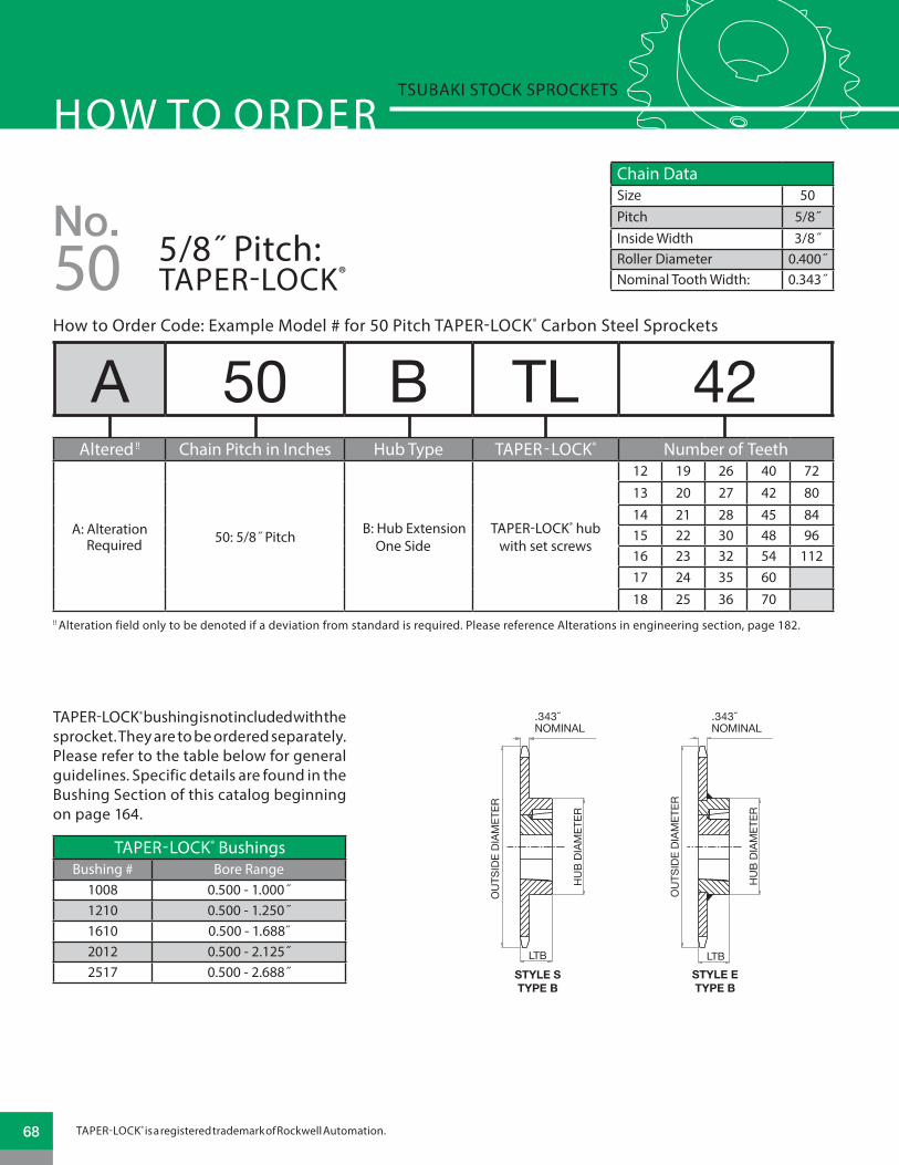
How to Order Code: Example Model # for 50 Pitch TAPER-LOCK® Carbon Steel Sprockets
!! Alteration field only to be denoted if a deviation from standard is required. Please reference Alterations in engineering section, page 182.
A 50 B TL 42Altered !! Chain Pitch in Inches Hub Type TAPER-LOCK® Number of Teeth
A: Alteration Required 50: 5/8˝ Pitch B: Hub Extension
One SideTAPER-LOCK® hub
with set screws
12 19 26 40 7213 20 27 42 8014 21 28 45 8415 22 30 48 9616 23 32 54 11217 24 35 6018 25 36 70
HOW TO ORDERTSUBAKI STOCK SPROCKETS
Chain DataSize 50Pitch 5/8˝Inside Width 3/8˝Roller Diameter 0.400˝Nominal Tooth Width: 0.343˝
No.5/8˝ Pitch: TAPER-LOCK®50
STYLE STYPE B
LTB
TOOTH (NOMINAL)
OU
TSID
EDI
AMET
ER
OU
TSID
EDI
AMET
ER
HU
BDI
AMET
ER
LTBSTYLE STYPE B
PLATE THICKNESSTOOTH (NOMINAL)
OU
TSID
EDI
AMET
ER
HU
BDI
AMET
ER
HU
BDI
AMET
ER
STYLE ETYPE B
LTB
TOOTH (NOMINAL)
SINGLE “TAPER-LOCK” STYLE DOUBLE “TAPER-LOCK” STYLE.343NOMINAL
.343NOMINAL
TAPER-LOCK® bushing is not included with the sprocket. They are to be ordered separately. Please refer to the table below for general guidelines. Specific details are found in the Bushing Section of this catalog beginning on page 164.
TAPER-LOCK® BushingsBushing # Bore Range
1008 0.500 - 1.000˝1210 0.500 - 1.250˝1610 0.500 - 1.688˝2012 0.500 - 2.125˝2517 0.500 - 2.688˝
TAPER-LOCK® is a registered trademark of Rockwell Automation.68
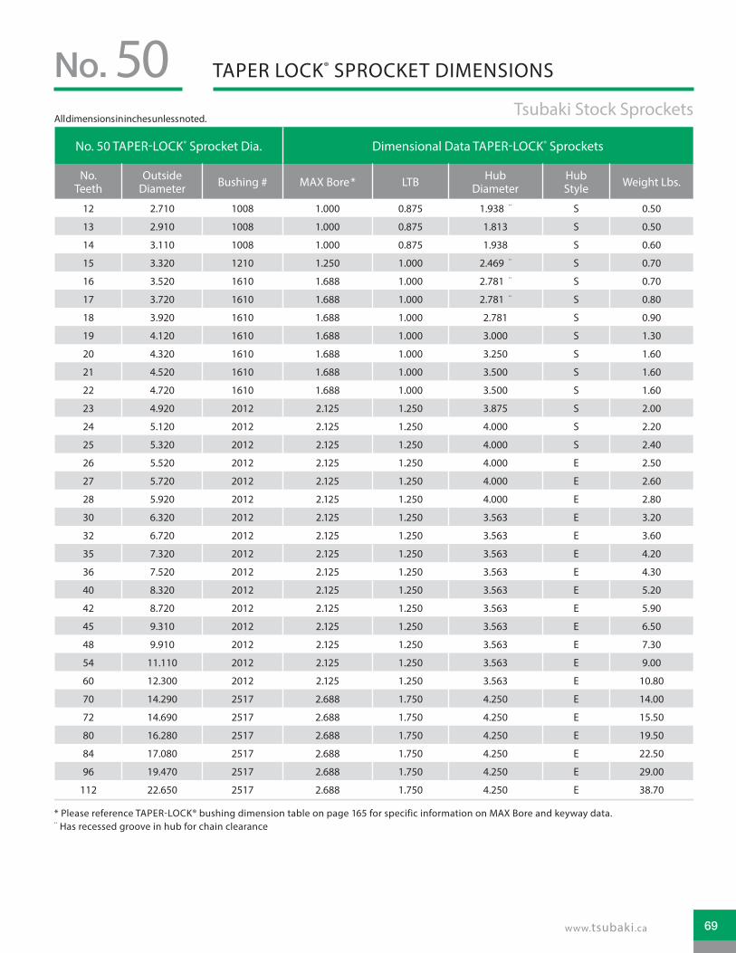
No. 50 TAPER-LOCK® Sprocket Dia. Dimensional Data TAPER-LOCK® Sprockets
No. Teeth
Outside Diameter Bushing # MAX Bore * LTB Hub
DiameterHub Style Weight Lbs.
12 2.710 1008 1.000 0.875 1.938 ¨ S 0.50
13 2.910 1008 1.000 0.875 1.813 S 0.50
14 3.110 1008 1.000 0.875 1.938 S 0.60
15 3.320 1210 1.250 1.000 2.469 ¨ S 0.70
16 3.520 1610 1.688 1.000 2.781 ¨ S 0.70
17 3.720 1610 1.688 1.000 2.781 ¨ S 0.80
18 3.920 1610 1.688 1.000 2.781 S 0.90
19 4.120 1610 1.688 1.000 3.000 S 1.30
20 4.320 1610 1.688 1.000 3.250 S 1.60
21 4.520 1610 1.688 1.000 3.500 S 1.60
22 4.720 1610 1.688 1.000 3.500 S 1.60
23 4.920 2012 2.125 1.250 3.875 S 2.00
24 5.120 2012 2.125 1.250 4.000 S 2.20
25 5.320 2012 2.125 1.250 4.000 S 2.40
26 5.520 2012 2.125 1.250 4.000 E 2.50
27 5.720 2012 2.125 1.250 4.000 E 2.60
28 5.920 2012 2.125 1.250 4.000 E 2.80
30 6.320 2012 2.125 1.250 3.563 E 3.20
32 6.720 2012 2.125 1.250 3.563 E 3.60
35 7.320 2012 2.125 1.250 3.563 E 4.20
36 7.520 2012 2.125 1.250 3.563 E 4.30
40 8.320 2012 2.125 1.250 3.563 E 5.20
42 8.720 2012 2.125 1.250 3.563 E 5.90
45 9.310 2012 2.125 1.250 3.563 E 6.50
48 9.910 2012 2.125 1.250 3.563 E 7.30
54 11.110 2012 2.125 1.250 3.563 E 9.00
60 12.300 2012 2.125 1.250 3.563 E 10.80
70 14.290 2517 2.688 1.750 4.250 E 14.00
72 14.690 2517 2.688 1.750 4.250 E 15.50
80 16.280 2517 2.688 1.750 4.250 E 19.50
84 17.080 2517 2.688 1.750 4.250 E 22.50
96 19.470 2517 2.688 1.750 4.250 E 29.00
112 22.650 2517 2.688 1.750 4.250 E 38.70
TAPER LOCK® SPROCKET DIMENSIONSNo. 50 Tsubaki Stock Sprockets
* Please reference TAPER-LOCK® bushing dimension table on page 165 for specific information on MAX Bore and keyway data.¨ Has recessed groove in hub for chain clearance
All dimensions in inches unless noted.
69www.tsubaki.ca

How to Order Code: Example Model # for 50 Pitch Multi-Strand TAPER-LOCK® Carbon Steel Sprockets
!! Alteration field only to be denoted if a deviation from standard is required. Please reference Alterations in engineering section, page 182.
A D 50 C TL 42Altered !! Multi-Strand Chain Pitch
in Inches Hub Type TAPER-LOCK® Number of Teeth
A: Alteration Required D: Double Strand 50: 5/8˝ Pitch
A: No Hub Extension
TAPER-LOCK® hub with set screws
A Style
14 16 18
15 17 19
B: Hub Extension One Side
B Style
20 25
21 30
C: Hub Extension Both Sides
C Style
36 48 60 84
42 52 60
HOW TO ORDERTSUBAKI STOCK SPROCKETS
Chain DataSize 50-2Pitch 5/8˝Inside Width 3/8˝Roller Diameter 0.400˝Nominal Tooth Width: 0.332˝
No.5/8˝ Pitch: MULTI-STRAND TAPER-LOCK®50
TAPER-LOCK® bushing is not included with the sprocket. They are to be ordered separately. Please refer to the table below for general guidelines. Speci�c details are found in the Bushing Section of this catalog beginning on page 164.
TAPER-LOCK® BushingsBushing # Bore Range
1008 0.500 - 1.000˝1210 0.500 - 1.250˝1610 0.500 - 1.688˝2012 0.500 - 2.125˝2517 0.500 - 2.688˝
TAPER-LOCK® is a registered trademark of Rockwell Automation.70
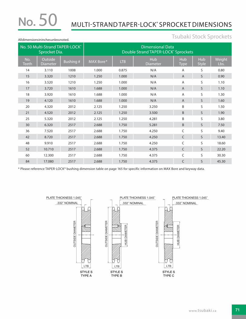
Tsubaki Stock Sprockets
No. 50No. 50 Multi-Strand TAPER-LOCK®
Sprocket Dia.Dimensional Data
Double Strand TAPER-LOCK® Sprockets
No. Teeth
Outside Diameter Bushing # MAX Bore * LTB Hub
DiameterHub Type
Hub Style
Weight Lbs.
14 3.110 1008 1.000 0.875 N/A A S 0.80
15 3.320 1210 1.250 1.000 N/A A S 0.90
16 3.520 1210 1.250 1.000 N/A A S 1.10
17 3.720 1610 1.688 1.000 N/A A S 1.10
18 3.920 1610 1.688 1.000 N/A A S 1.30
19 4.120 1610 1.688 1.000 N/A A S 1.60
20 4.320 2012 2.125 1.250 3.250 B S 1.50
21 4.520 2012 2.125 1.250 3.500 B S 1.90
25 5.320 2012 2.125 1.250 4.281 B S 3.80
30 6.320 2517 2.688 1.750 5.281 B S 7.50
36 7.520 2517 2.688 1.750 4.250 C S 9.40
42 8.720 2517 2.688 1.750 4.250 C S 13.40
48 9.910 2517 2.688 1.750 4.250 C S 18.60
52 10.710 2517 2.688 1.750 4.375 C S 22.20
60 12.300 2517 2.688 1.750 4.375 C S 30.30
84 17.080 2517 2.688 1.750 4.375 C S 45.30
MULTI-STRAND TAPER-LOCK® SPROCKET DIMENSIONS
* Please reference TAPER-LOCK® bushing dimension table on page 165 for specific information on MAX Bore and keyway data.
TOOTH (NOMINAL)PLATE THICKNESS
OU
TSID
E DI
AMET
ER
HU
B DI
AMET
ER
LTB
TOOTH (NOMINAL)PLATE THICKNESS
LTB
OU
TSID
E DI
AMET
ER
OU
TSID
E DI
AMET
ER
HU
B DI
AMET
ER
LTB
PLATE THICKNESSTOOTH (NOMINAL)
STYLE STYPE A
STYLE STYPE B
STYLE STYPE C
.332 NOMINAL .332 NOMINAL .332 NOMINAL
PLATE T ICKNESS 1.045 PLATE T ICKNESS 1.045 PLATE T ICKNESS 1.045
All dimensions in inches unless noted.
71www.tsubaki.ca

!! Alteration field only to be denoted if a deviation from standard required. Please reference alterations in engineering section
A 50 SH 19How to Order Code: Example Model # for 50 Pitch QD® Carbon Steel Sprockets
HOW TO ORDERTSUBAKI STOCK SPROCKETS
Chain DataSize 50Pitch 5/8˝Inside Width 3/8˝Roller Diameter 0.400˝Nominal Tooth Width: 0.343˝
Altered !! Chain Pitch in Inches QD® Hub Type Number of Teeth
A: Alteration Required 50: 5/8˝ Pitch
JA: QD® Hub 12 - 16 tooth sprocket
12 14 16
13 15
SH: QD® Hub 17 - 19 tooth sprocket
17 19
18
SDS: QD® Hub 20 - 48 tooth sprocket
20 24 28 36 48
21 25 30 40
22 26 32 42
23 27 35 45
SK: QD® Hub 54 - 72 tooth sprocket
54 70
60 72
SF: QD® Hub 80 - 112 tooth sprocket
80 96
84 112
No.50 5/8˝ Pitch: QD®
!! Alteration field only to be denoted if a deviation from standard is required. Please reference Alterations in engineering section, page 182.
QD® bushing is not included with the sprocket. They are to be ordered separately. Please refer to the table below for general guidelines. Specific details are found in the Bushing Section of this catalog beginning on page 170.
QD® BushingsBushing # Bore Range
JA 0.500 - 1.250˝SH 0.500 - 1.688˝
SDS 0.500 - 2.000˝SK 0.500 - 2.625˝SF 0.500 - 2.938˝
QD® is a registered trademark of, and is used under license agreement from Emerson Electric Co.72

QD® SPROCKET DIMENSIONSNo. 50 Tsubaki Stock Sprockets
No. 50 QD® Sprocket Dia. Dimensional Data QD® Sprockets
No. Teeth
Outside Dia.
QD® Bushing #
MAX Bore *
Hub Dia. LTB X Y L F Hub
TypeHub Style
Weight Lbs.
12 2.710 JA 1.250 1.922 0.625 1.125 1.125 0.656 2.063 B S 0.3413 2.910 JA 1.250 2.063 0.625 1.125 1.125 0.656 2.063 B S 0.4014 3.110 JA 1.250 2.125 0.625 1.125 1.125 0.656 2.063 B S 0.5215 3.320 JA 1.250 2.250 0.625 1.125 1.125 0.656 2.063 B S 0.6016 3.520 JA 1.250 2.250 0.625 1.125 1.125 0.656 2.063 B S 0.6817 3.720 SH 1.688 2.750 0.813 1.437 1.437 0.906 2.688 B S 0.8418 3.920 SH 1.688 2.875 0.813 1.437 1.437 0.906 2.688 B S 1.0419 4.120 SH 1.688 3.000 0.813 1.437 1.437 0.906 2.688 B S 1.2420 4.320 SDS 2.000 3.313 0.750 1.500 1.500 0.969 3.188 B S 1.2021 4.520 SDS 2.000 3.500 0.750 1.500 1.500 0.969 3.188 B S 1.3222 4.720 SDS 2.000 3.500 0.750 1.500 1.500 0.969 3.188 B S 1.4223 4.920 SDS 2.000 3.500 0.750 1.500 1.500 0.969 3.188 B S 1.5824 5.120 SDS 2.000 3.625 0.750 1.500 1.500 0.969 3.188 B E 1.7025 5.320 SDS 2.000 3.625 0.750 1.500 1.500 0.969 3.188 B E 1.8626 5.520 SDS 2.000 3.625 0.750 1.500 1.500 0.969 3.188 B E 2.0027 5.720 SDS 2.000 3.625 0.750 1.500 1.500 0.969 3.188 B E 2.1228 5.920 SDS 2.000 3.625 0.750 1.500 1.500 0.969 3.188 B E 2.3230 6.320 SDS 2.000 3.625 0.750 1.500 1.500 0.969 3.188 B E 2.6432 6.720 SDS 2.000 3.625 0.750 1.500 1.500 0.969 3.188 B E 2.9835 7.320 SDS 2.000 3.625 0.750 1.500 1.500 0.969 3.188 B E 3.6236 7.520 SDS 2.000 3.625 0.750 1.500 1.500 0.969 3.188 B E 3.6440 8.320 SDS 2.000 3.625 0.750 1.500 1.500 0.969 3.188 B E 4.7442 8.720 SDS 2.000 3.625 0.750 1.500 1.500 0.969 3.188 B E 5.4045 9.310 SDS 2.000 3.625 0.750 1.500 1.500 0.969 3.188 B E 5.9048 9.910 SDS 2.000 3.625 0.750 1.500 1.500 0.969 3.188 B E 6.6654 11.110 SK 2.625 3.625 1.250 2.125 2.125 1.531 3.875 B E 9.6860 12.300 SK 2.625 4.250 1.250 2.125 2.125 1.531 3.875 B E 11.8870 14.290 SK 2.625 4.250 1.250 2.125 2.125 1.531 3.875 B E 15.5272 14.690 SK 2.625 4.250 1.250 2.125 2.125 1.531 3.875 B E 16.4480 16.280 SF ** 2.938 5.000 1.250 2.250 2.250 1.656 4.625 B E 19.9084 17.080 SF ** 2.938 5.000 1.250 2.250 2.250 1.656 4.625 B E 22.9896 19.470 SF ** 2.938 5.000 1.250 2.250 2.250 1.656 4.625 B E 29.88
112 22.650 SF ** 2.938 5.000 1.250 2.250 2.250 1.656 4.625 B E 40.10
STYLE STYPE B
X
L
YLTB
OU
TSID
EDI
AMET
ER
HU
BDI
AMET
ER
Y
HU
BDI
AMET
ER
OU
TSID
EDI
AMET
ER
F F
STYLE ETYPE B
X
L
LTBTOOTH(NOMINAL)
TOOTH(NOMINAL)
.343NOMINAL
.343NOMINAL
* Please reference QD® bushing dimension table on page 171 for specific information on MAX Bore and keyway data.** = Max Bore with shallow key
All dimensions in inches unless noted.
73www.tsubaki.ca

Chain DataSize 60Pitch 3/4˝Inside Width 1/2˝Roller Diameter 0.469˝Nominal Tooth Width: 0.459˝
HOW TO ORDERTSUBAKI STOCK SPROCKETS
A 60 A 37Altered !! Chain Pitch in Inches Hub Type Number of Teeth
A: Alteration Required
60: 3/4˝ Pitch
A: No Hub Extension
10 20 30 40 50 6011 21 31 41 51 7012 22 32 42 52 7213 23 33 43 53 8014 24 34 44 54 8415 25 35 45 55 9616 26 36 46 56 11217 27 37 47 5718 28 38 48 5819 29 39 49 59
B: Hub Extension One Side
8 19 30 42 53 8419 20 31 43 54 9610 21 32 44 55 11211 22 33 45 5612 23 34 46 5713 24 35 47 5814 25 36 48 5915 26 37 49 6016 27 38 50 7017 28 39 51 7218 29 40 52 80
How to Order Code: Example Model # for 60 Pitch Plain Bore Carbon Steel Sprockets
No.3/4˝ Pitch: PLAIN BORE60
!! Alteration field only to be denoted if a deviation from standard is required. Please reference Alterations in engineering section, page 182.
LTBLTB
OU
TSID
EDI
AMET
ER
OU
TSID
EDI
AMET
ER
OU
TSID
EDI
AMET
ER
BORE
BORE
BORE
HU
BDI
AMET
ER
HU
BDI
AMET
ER
STYLE ETYPE B
STYLE STYPE B
TYPE A
TOOTH(NOMINAL)
TOOTH(NOMINAL)
TOOTH(NOMINAL)
.459NOMINAL
.459NOMINAL
.459NOMINAL
74

PLAIN BORE SPROCKET DIMENSIONSNo. 60 Tsubaki Stock Sprockets
No. 60 Plain Bore Sprocket Dia. Type “A” Plain Bore Type “B” Plain Bore
No. Teeth
Outside Dia.
Pitch Dia.
Caliper Dia.
Plain Bore
Wt. Lbs.
Plain Bore
MAX Bore *
Hub Dia. LTB Hub
StyleWt. Lbs.
8 2.260 1.959 1.491 NS NS 0.625 0.625 1.469 ¨ 1.250 S 0.549 2.510 2.193 1.691 NS NS 0.750 0.875 1.563 ¨ 1.250 S 0.64
10 2.760 2.427 1.958 0.750 0.44 0.750 1.125 1.938 ¨ 1.250 S 0.9911 3.000 2.663 2.166 0.750 0.54 0.750 1.313 2.063 ¨ 1.250 S 1.1512 3.250 2.898 2.429 0.750 0.68 0.750 1.375 2.375 ¨ 1.250 S 1.4713 3.490 3.134 2.642 0.750 0.80 0.750 1.500 2.344 1.250 S 1.6614 3.740 3.371 2.902 0.750 0.94 0.750 1.750 2.563 1.250 S 2.0015 3.980 3.608 3.119 0.750 1.08 0.750 1.875 2.875 1.250 S 2.5116 4.220 3.845 3.375 0.750 1.24 0.750 2.000 3.063 1.250 S 2.8117 4.460 4.082 3.595 0.750 1.44 0.750 2.250 3.250 1.250 S 3.2218 4.700 4.319 3.850 0.750 1.62 0.750 2.375 3.500 1.250 E 3.7219 4.950 4.557 4.072 0.750 1.84 0.750 2.375 3.500 1.250 E 3.9220 5.190 4.794 4.325 0.750 2.12 0.750 2.625 3.875 1.250 E 4.6321 5.430 5.033 4.549 0.750 2.28 0.750 2.750 4.000 1.250 E 5.0022 5.670 5.270 4.801 0.750 2.48 0.750 2.750 4.000 1.250 E 5.2523 5.910 5.508 5.026 0.750 2.68 0.750 2.750 4.000 1.250 E 5.4824 6.150 5.746 5.277 0.719 3.00 0.750 2.750 4.000 1.250 E 5.7825 6.390 5.984 5.503 0.719 3.34 0.750 2.750 4.000 1.250 E 6.1326 6.630 6.222 5.753 0.719 3.54 0.750 2.750 4.000 1.250 E 6.3827 6.870 6.461 5.980 0.719 3.96 0.750 2.750 4.000 1.250 E 6.7228 7.110 6.698 6.229 0.719 4.14 0.750 2.750 4.000 1.250 E 6.8829 7.350 6.937 6.458 0.719 4.40 0.750 2.750 4.000 1.250 E 7.2830 7.590 7.175 6.706 0.719 4.78 0.750 2.750 4.000 1.250 E 7.5831 7.830 7.413 6.935 0.719 5.24 0.750 2.750 4.000 1.250 E 7.7232 8.070 7.652 7.183 0.719 5.52 0.750 2.750 4.000 1.250 E 8.2633 8.300 7.890 7.412 0.938 5.86 1.000 2.750 4.000 1.250 E 8.4234 8.540 8.129 7.660 0.938 6.16 1.000 2.750 4.000 1.250 E 8.8035 8.780 8.367 7.889 0.938 6.78 1.000 2.750 4.000 1.250 E 9.0436 9.020 8.606 8.137 0.938 6.82 1.000 2.750 4.000 1.250 E 9.6037 9.260 8.844 8.367 0.938 7.52 1.000 2.750 4.000 1.250 E 10.2438 9.500 9.083 8.614 0.938 7.84 1.000 2.750 4.250 1.250 E 10.8439 9.740 9.321 8.844 0.938 8.28 1.000 2.750 4.250 1.250 E 11.3640 9.980 9.560 9.091 0.938 8.56 1.000 2.750 4.250 1.250 E 11.5041 10.220 9.798 9.321 0.938 9.10 1.000 2.750 4.250 1.250 E 12.1442 10.460 10.037 9.568 0.938 9.74 1.000 2.750 4.250 1.250 E 12.7443 10.700 10.275 9.799 0.938 9.84 1.000 2.750 4.250 1.250 E 13.0044 10.940 10.514 10.045 0.938 10.76 0.938 2.750 4.250 1.250 E 13.8845 11.180 10.752 10.276 0.938 11.08 0.938 2.750 4.250 1.250 E 13.9846 11.420 10.991 10.522 0.938 11.50 0.938 2.750 4.250 1.250 E 14.6047 11.650 11.229 10.754 0.938 12.32 0.938 2.750 4.250 1.250 E 15.0048 11.890 11.468 10.999 0.938 12.42 0.938 2.750 4.250 1.250 E 15.8249 12.130 11.706 11.231 0.938 12.92 0.938 2.750 4.250 1.250 E 15.9050 12.370 11.945 11.476 0.938 13.98 0.938 2.750 4.250 1.250 E 16.9851 12.610 12.183 11.708 0.938 14.58 0.938 2.750 4.250 1.250 E 17.6652 12.850 12.422 11.953 0.938 14.60 0.938 2.750 4.250 1.250 E 17.9353 13.090 12.660 12.186 0.938 15.84 0.938 2.750 4.250 1.250 E 17.9954 13.330 12.889 12.430 0.938 15.92 0.938 2.750 4.250 1.750 E 21.6055 13.570 13.137 12.663 1.250 16.96 1.250 2.750 4.250 1.750 E 21.1456 13.810 13.376 12.907 1.250 17.60 1.250 2.750 4.250 1.750 E 21.8857 14.040 13.615 13.140 1.250 17.62 1.250 2.750 4.250 1.750 E 22.2558 14.280 13.853 13.384 1.250 19.00 1.250 2.750 4.250 1.750 E 22.8059 14.520 14.092 13.618 1.250 19.20 1.250 2.750 4.250 1.750 E 23.8660 14.760 14.330 13.861 1.250 20.02 1.250 2.750 4.250 1.750 E 25.2270 17.150 16.717 16.248 1.250 27.20 1.250 2.750 4.250 1.750 E 31.9872 17.630 17.195 16.726 1.250 28.90 1.250 2.750 4.250 1.750 E 34.1880 19.540 19.103 18.634 1.250 40.18 1.250 2.750 4.250 2.000 E 41.8884 20.490 20.058 19.589 1.250 45.50 1.250 3.250 4.750 2.000 E 46.4696 23.360 22.922 22.453 1.250 52.02 1.250 3.750 5.500 2.250 E 63.08
112 27.180 26.741 26.272 1.250 70.80 1.250 3.750 5.500 2.250 E 81.78
* Dimensions shown allow for standard keyway with set screw at 90 degrees¨ Has recessed groove in hub for chain clearanceNS = Non Stock
All dimensions in inches unless noted.
75www.tsubaki.ca

HOW TO ORDERTSUBAKI STOCK SPROCKETS
Chain DataSize 60Pitch 3/4˝Inside Width 1/2˝Roller Diameter 0.469˝Nominal Tooth Width: 0.459˝
How to Order Code: Example Model # for 60 Pitch Finished Bore Carbon Steel Sprockets
60 B 36 F - 2
No.3/4˝ Pitch: FINISHED BORE60
Chain Pitch in Inches Hub Type Number of Teeth Finished Bore Hub Bore**
60: 3/4˝ PitchB: Hub Extension One Side
9 21 33 45 57
F: Hub Extension Machined with keyway and two set screws
J 5/8" (0.625")10 22 34 46 58 L 3/4" (0.750")11 23 35 47 59 P 7/8" (0.875")12 24 36 48 60 1 1" (1.000")13 25 37 49 70 1B 1-1/8" (1.125")14 26 38 50 72 1C 1-3/16" (1.188")15 27 39 51 80 1D 1-1/4" (1.250")16 28 40 52 84 1F 1-3/8" (1.375")
17 29 41 53 96 1G: 1-7/16" (1.438")
18 30 42 54 112 1H: 1-1/2" (1.500")
19 31 43 55 1J 1-5/8" (1.625")
20 32 44 56 1L 1-3/4" (1.750")
1R 1-15/16" (1.938")
2 2" (2.000")
2C 2-3/16" (2.188")
2G 2-7/16" (2.438")
** Hub bore size should be selected from dimensional table on the following page. Bore sizes that are not listed for a given number of sprocket teeth may be available per request as Altered.
OU
TSID
EDI
AMET
ER
BORE
HU
BDI
AMET
ER
STYLE ETYPE B
LTB
TOOTH (NOMINAL)
STYLE STYPE B
LTB
TOOTH (NOMINAL)
OU
TSID
EDI
AMET
ER
BORE
HU
BDI
AMET
ER
.459NOMINAL
.459NOMINAL
76

FINISHED BORE SPROCKET DIMENSIONSNo. 60 Tsubaki Stock Sprockets
No. 60 Finished Bore Sprocket Dia.
Type “F” Bored to Shaft Size (includes standard keyway and two set screws)
No. Teeth
Outside Dia.
Pitch Dia.
Caliper Dia. .7
50"
.875
"
1.00
0"
1.12
5"
1.18
8"
1.25
0"
1.37
5"
1.43
8"
1.50
0"
1.62
5"
1.75
0"
1.93
8"
2.00
0"
2.18
8"
2.43
8"
9 2.510 2.193 1.691 • • •10 2.760 2.427 1.958 • • • • • • ¢11 3.000 2.663 2.166 • • • • • • ¢12 3.250 2.898 2.429 • • • • • • ¢ • ¢ • ¢13 3.490 3.134 2.642 • • • • • • • ¢ • ¢ • ¢14 3.740 3.371 2.902 • • • • • • • • • ¢ • ¢15 3.980 3.608 3.119 • • • • • • • • • • • ¢16 4.220 3.845 3.375 • • • • • • • • • • • • ¢17 4.460 4.082 3.595 • • • • • • • • • • ¢18 4.700 4.319 3.850 • • • • • • • • • •19 4.950 4.557 4.072 • • • • • • • • • •20 5.190 4.794 4.325 • • • • • • • • • •21 5.430 5.033 4.549 • • • • • • • • • •22 5.670 5.270 4.801 • • • • • • • • • •23 5.910 5.508 5.026 • • • • • • • • • •24 6.150 5.746 5.277 • • • • • • • • • •25 6.390 5.984 5.503 • • • • • • • • • •26 6.630 6.222 5.753 • • • • • • • • • •27 6.870 6.461 5.98 • • • • • • • • • •28 7.110 6.698 6.229 • • • • • • • • • •29 7.350 6.937 6.458 • • • • • • • • • •30 7.590 7.175 6.706 • • • • • • • • • •31 7.830 7.413 6.935 • • • • • • • • • •32 8.070 7.652 7.183 • • • • • • • • • •33 8.300 7.890 7.412 • • • • • • • • • •34 8.540 8.129 7.660 • • • • • • • • • •35 8.780 8.367 7.889 • • • • • • • • • •36 9.020 8.606 8.137 • • • • • • • • • • • • •37 9.260 8.844 8.367 • • • • • • • • • • • • •38 9.500 9.083 8.614 • • • • • • • • • • • • •39 9.740 9.321 8.844 • • • • • • • • • • • • •40 9.980 9.560 9.091 • • • • • • • • • • • • •41 10.220 9.798 9.321 • • • • • • • • • • • • •42 10.460 10.037 9.568 • • • • • • • • • • • • •43 10.700 10.275 9.799 • • • • • • • • • • • • •44 10.940 10.514 10.045 • • • • • • • • • • • • •45 11.180 10.752 10.276 • • • • • • • • • • • • •46 11.420 10.991 10.522 • • • • • • • • • • • • •47 11.650 11.229 10.754 • • • • • • • • • • • • •48 11.890 11.468 10.999 • • • • • • • • • • • • •49 12.130 11.706 11.231 • • • • • • • • • • • • •50 12.370 11.945 11.476 • • • • • • • • • • • • •51 12.610 12.183 11.708 • • • • • • • • • • • • •52 12.850 12.422 11.953 • • • • • • • • • • • • •53 13.090 12.660 12.186 • • • • • • • • • • • • •54 13.330 12.889 12.430 • • • • • • • • • • • • •55 13.570 13.137 12.663 • • • • • • • • •56 13.810 13.376 12.907 • • • • • • • • •57 14.040 13.615 13.140 • • • • • • • • •58 14.280 13.853 13.384 • • • • • • • • •59 14.520 14.092 13.618 • • • • • • • • •60 14.760 14.330 13.861 • • • • • • • • •70 17.150 16.717 16.248 • • • • • • • • •72 17.630 17.195 16.726 • • • • • • • • •80 19.540 19.103 18.634 • • • • • • • • •84 20.490 20.058 19.589 • • • • • • • • •96 23.360 22.922 22.453 • • • • • • • • •
112 27.180 26.741 26.272 • • • • • • • • •
• Denotes stocking item ¢ Indicates ser screw at 90 degrees and 180 degrees from keyway
All dimensions in inches unless noted.
77www.tsubaki.ca

HOW TO ORDERTSUBAKI STOCK SPROCKETS
Chain DataSize 60SSPitch 3/4˝Inside Width 1/2˝Roller Diameter 0.469 ˝Nominal Tooth Width: 0.459˝
How to Order Code: Example Model # for 60 Pitch Plain Bore Stainless Steel Sprockets
!! Alteration field only to be denoted if a deviation from standard is required. Please reference Alterations in engineering section, page 182.
A 60 B 25 SS
No.3/4˝ Pitch: STAINLESS STEEL PLAIN BORE60
Altered !! Chain Pitch in Inches Hub Type: Number of Teeth Material
A: Alteration Required
60: 3/4˝ PitchB: Hub
Extension One Side
12 17 21 25 35
SS: 304 Stainless Steel Construction
13 18 22 26 40
14 19 23 28 45
15 20 24 30 60
16
B: Hub Extension One Side
78

STAINLESS STEEL SPROCKET DIMENSIONSNo. 60 Tsubaki Stock Sprockets
No. 60 Stainless Steel Sprocket Diameters Type “B” Plain Bore
No. Teeth Outside Diameter
Pitch Diameter
Caliper Diameter Plain Bore MAX Bore* Hub Dia. LTB Hub
StyleWt. Lbs.
12 3.250 2.898 2.429 0.750 1.375 2.375 ¨ 1.250 S 1.50
13 3.490 3.134 2.642 0.750 1.500 2.344 1.250 S 1.80
14 3.740 3.371 2.902 0.750 1.750 2.563 1.250 S 2.00
15 3.980 3.608 3.119 0.750 1.875 2.875 1.250 S 2.40
16 4.220 3.845 3.375 0.750 2.000 3.063 1.250 S 2.80
17 4.460 4.082 3.595 0.750 2.250 3.250 1.250 E 3.30
18 4.700 4.319 3.850 0.750 2.375 3.500 1.250 E 3.80
19 4.950 4.557 4.072 0.750 2.375 3.500 1.250 E 4.00
20 5.190 4.794 4.325 0.750 2.625 3.875 1.250 E 4.60
21 5.430 5.033 4.549 0.750 2.750 4.000 1.250 E 5.00
22 5.670 5.270 4.801 0.750 2.750 4.000 1.250 E 5.30
23 5.910 5.508 5.026 0.750 2.750 4.000 1.250 E 5.70
24 6.150 5.746 5.277 0.750 2.750 4.000 1.250 E 5.90
25 6.390 5.984 5.503 0.750 2.750 4.000 1.250 E 6.10
26 6.630 6.222 5.753 0.750 2.750 4.000 1.250 E 6.30
28 7.110 6.698 6.229 0.750 2.750 4.000 1.250 E 6.70
30 7.590 7.175 6.706 0.750 2.750 4.000 1.250 E 7.00
35 8.780 8.367 7.889 1.000 2.750 4.000 1.250 E 9.00
40 9.980 9.560 9.091 1.000 2.750 4.250 1.250 E 11.70
45 11.180 10.752 10.276 1.000 2.750 4.250 1.250 E 14.50
60 14.760 14.330 13.861 1.250 2.750 4.250 1.750 E 25.00
* Dimensions shown allow for standard keyway with set screw at 90 degrees¨ Has recessed groove in hub for chain clearance
LTBLTB
OU
TSID
EDI
AMET
ER
OU
TSID
EDI
AMET
ER
OU
TSID
EDI
AMET
ER
BORE
BORE
BORE
HU
BDI
AMET
ER
HU
BDI
AMET
ER
STYLE ETYPE B
STYLE STYPE B
TYPE A
TOOTH(NOMINAL)
TOOTH(NOMINAL)
TOOTH(NOMINAL)
LTB
OU
TSID
EDI
AMET
ER
BORE
HU
BDI
AMET
ER
STYLE DTYPE B
TOOTH(NOMINAL)
.459NOMINAL
.459NOMINAL
.459NOMINAL
All dimensions in inches unless noted.
79www.tsubaki.ca

HOW TO ORDERTSUBAKI STOCK SPROCKETS
Chain DataSize 60-2, 60-3Pitch 3/4˝Inside Width 1/2˝Roller Diameter 0.469 ˝Nominal Tooth Width: 0.444˝
How to Order Code: Example Model # for 60 Pitch Multi-Strand Carbon Steel Sprockets
A D 60 B 18Altered !! Multi Chain Pitch in Inches Hub Type Number of Teeth
A: Alteration Required
D: Double Strand
60: 3/4˝ PitchB: Hub Extension One Side
Double Strand11 16 21 26 4012 17 22 30 4513 18 23 32 4814 19 24 35 60
15 20 25 36
T: Triple Strand
Triple Strand
11 15 19 23 30
12 16 20 24 35
13 17 21 25 36
14 18 22 26
No.3/4˝ Pitch: MULTI-STRAND60
!! Alteration field only to be denoted if a deviation from standard is required. Please reference Alterations in engineering section, page 182.
OU
TSID
EDI
AMET
ER
OU
TSID
EDI
AMET
ER
BORE
OU
TSID
EDI
AMET
ERBO
RE
BORE
HU
BDI
AMET
ER
HU
BDI
AMET
ER
HU
BDI
AMET
ER
OU
TSID
EDI
AMET
ERBO
RE
HU
BDI
AMET
ER
STYLE STYPE B
STYLE STYPE B
STYLE DTYPE B
DOUBLE STRAND DOUBLE STRAND TRIPLE STRAND TRIPLE STRAND
LTB
STYLE DTYPE B
LTB LTB LTB
TOOTH (NOMINAL)TOOTH (NOMINAL)PLATE THICKNESS
TOOTH (NOMINAL)PLATE THICKNESS PLATE THICKNESS
PLATE T ICKNESS 1. 41
PLATE T ICKNESS 1. 41
PLATE T ICKNESS 2.2 8
PLATE T ICKNESS 2.2 8
.444 NOMINAL .444 NOMINAL .444 NOMINAL .444 NOMINAL
80
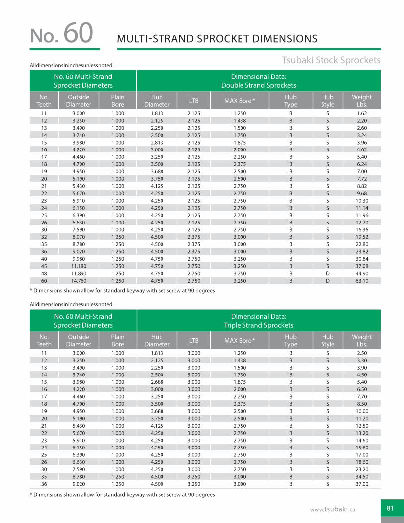
MULTI-STRAND SPROCKET DIMENSIONSNo. 60 Tsubaki Stock Sprockets
No. 60 Multi-Strand Sprocket Diameters
Dimensional Data: Double Strand Sprockets
No. Teeth
Outside Diameter
Plain Bore
Hub Diameter LTB MAX Bore * Hub
TypeHub Style
Weight Lbs.
11 3.000 1.000 1.813 2.125 1.250 B S 1.6212 3.250 1.000 2.125 2.125 1.438 B S 2.2013 3.490 1.000 2.250 2.125 1.500 B S 2.6014 3.740 1.000 2.500 2.125 1.750 B S 3.2415 3.980 1.000 2.813 2.125 1.875 B S 3.9616 4.220 1.000 3.000 2.125 2.000 B S 4.6217 4.460 1.000 3.250 2.125 2.250 B S 5.4018 4.700 1.000 3.500 2.125 2.375 B S 6.2419 4.950 1.000 3.688 2.125 2.500 B S 7.0020 5.190 1.000 3.750 2.125 2.500 B S 7.7221 5.430 1.000 4.125 2.125 2.750 B S 8.8222 5.670 1.000 4.250 2.125 2.750 B S 9.6823 5.910 1.000 4.250 2.125 2.750 B S 10.3024 6.150 1.000 4.250 2.125 2.750 B S 11.1425 6.390 1.000 4.250 2.125 2.750 B S 11.9626 6.630 1.000 4.250 2.125 2.750 B S 12.7030 7.590 1.000 4.250 2.125 2.750 B S 16.3632 8.070 1.250 4.500 2.375 3.000 B S 19.5235 8.780 1.250 4.500 2.375 3.000 B S 22.8036 9.020 1.250 4.500 2.375 3.000 B S 23.8240 9.980 1.250 4.750 2.750 3.250 B S 30.8445 11.180 1.250 4.750 2.750 3.250 B S 37.0848 11.890 1.250 4.750 2.750 3.250 B D 44.9060 14.760 1.250 4.750 2.750 3.250 B D 63.10
No. 60 Multi-Strand Sprocket Diameters
Dimensional Data: Triple Strand Sprockets
No. Teeth
Outside Diameter
Plain Bore
Hub Diameter LTB MAX Bore * Hub
TypeHub Style
Weight Lbs.
11 3.000 1.000 1.813 3.000 1.250 B S 2.5012 3.250 1.000 2.125 3.000 1.438 B S 3.3013 3.490 1.000 2.250 3.000 1.500 B S 3.9014 3.740 1.000 2.500 3.000 1.750 B S 4.5015 3.980 1.000 2.688 3.000 1.875 B S 5.4016 4.220 1.000 3.000 3.000 2.000 B S 6.5017 4.460 1.000 3.250 3.000 2.250 B S 7.7018 4.700 1.000 3.500 3.000 2.375 B S 8.5019 4.950 1.000 3.688 3.000 2.500 B S 10.0020 5.190 1.000 3.750 3.000 2.500 B S 11.2021 5.430 1.000 4.125 3.000 2.750 B S 12.5022 5.670 1.000 4.250 3.000 2.750 B S 13.2023 5.910 1.000 4.250 3.000 2.750 B S 14.6024 6.150 1.000 4.250 3.000 2.750 B S 15.8025 6.390 1.000 4.250 3.000 2.750 B S 17.0026 6.630 1.000 4.250 3.000 2.750 B S 18.6030 7.590 1.000 4.250 3.000 2.750 B S 23.2035 8.780 1.250 4.500 3.250 3.000 B S 34.5036 9.020 1.250 4.500 3.250 3.000 B S 37.00
* Dimensions shown allow for standard keyway with set screw at 90 degrees
* Dimensions shown allow for standard keyway with set screw at 90 degrees
All dimensions in inches unless noted.
All dimensions in inches unless noted.
81www.tsubaki.ca

HOW TO ORDERTSUBAKI STOCK SPROCKETS
Chain DataSize 60Pitch 3/4˝Inside Width 1/2˝Roller Diameter 0.469˝Nominal Tooth Width: 0.459˝
!! Alteration field only to be denoted if a deviation from standard is required. Please reference Alterations in engineering section, page 182.
!! Alteration field only to be denoted if a deviation from standard is required. Please reference Alterations in engineering section, page 182.
A DS 60 A 19
A DS 60 A TL 24
Altered !! Multi Chain Pitch in Inches Hub Type Number of Teeth
A: Alteration Required
DS: Double Single 60: 3/4˝ Pitch A: No Hub
Extension
13 17 2114 1815 1916 20
Altered !! Multi Chain Pitch in Inches Hub Type TAPER-LOCK® Number of Teeth
A: Alteration Required
DS: Double Single
60: 3/4˝ Pitch A: No Hub Extension
TAPER-LOCK® hub with set
screws
17 21
18 23
19 24
20
How to Order Code: Example Model # for 60 Pitch Double Single Carbon Steel Sprockets
How to Order Code: Example Model # for 60 Pitch Double Single TAPER-LOCK® Carbon Steel Sprockets
No.3/4˝ Pitch: DOUBLE SINGLE60
TAPER-LOCK® bushing is not included with the sprocket. They are to be ordered separately. Please refer to the table below for general guidelines. Speci�c details are found in the Bushing Section of this catalog beginning on page 164.
TAPER-LOCK® BushingsBushing # Bore Range
1615 0.500 - 1.688˝2012 0.500 - 2.125˝2517 0.500 - 2.688˝
TAPER-LOCK® is a registered trademark of Rockwell Automation.82

DOUBLE SINGLE SPROCKET DIMENSIONSNo. 60 Tsubaki Stock Sprockets
No. 60 Double Single Sprocket Diameters Dimensional Data: Double Single Sprockets
No. Teeth Outside Dia. Plain Bore LTB C D MAX Bore * Weight Lbs.
13 3.490 0.750 1.938 1.484 2.344 1.500 2.60
14 3.740 0.750 1.938 1.484 2.563 1.750 3.20
15 3.980 0.750 1.938 1.484 2.875 1.875 3.80
16 4.220 0.750 1.938 1.484 3.047 2.000 4.50
17 4.460 0.750 1.938 1.484 3.250 2.250 5.30
18 4.700 0.750 1.938 1.484 3.500 2.375 6.50
19 4.950 0.750 1.938 1.484 3.703 2.500 6.80
20 5.190 0.750 1.938 1.484 3.953 2.750 7.00
21 5.430 0.750 1.938 1.484 4.188 2.875 7.50
No. 60 Double Single TAPER-LOCK® Sprocket Diameters Dimensional Data: Double Single TAPER-LOCK® Sprockets
No. Teeth Outside Dia. Bushing # LTB C D MAX Bore * Weight Lbs.
17 4.460 1615 1.938 1.484 3.218 1.688 4.50
18 4.700 2012 1.938 1.484 3.469 2.125 5.00
19 4.950 2012 1.938 1.484 3.703 2.125 5.80
20 5.190 2517 1.938 1.484 3.953 2.688 5.60
21 5.430 2517 1.938 1.484 4.188 2.688 6.40
23 5.910 2517 1.938 1.484 4.672 2.688 7.30
24 6.150 2517 1.938 1.484 4.906 2.688 8.20
BORE
D
D
OU
TSID
EDI
AMET
ER
OU
TSID
EDI
AMET
ER
STOCK BOREDOUBLE SINGLE
TAPER-LOCK®
DOUBLE SINGLE
LTB
C C
LTB
.459 NOMINAL
BORE
D
D
OU
TSID
EDI
AMET
ER
OU
TSID
EDI
AMET
ER
STOCK BOREDOUBLE SINGLE
TAPER-LOCK®
DOUBLE SINGLE
LTB
C C
LTB
.459 NOMINAL
* Dimensions shown allow for standard keyway with set screw at 90 degrees
* Please reference TAPER-LOCK® bushing dimension table on page 165 for specific information on MAX Bore and keyway data.
All dimensions in inches unless noted.
All dimensions in inches unless noted.
83www.tsubaki.ca

HOW TO ORDERTSUBAKI STOCK SPROCKETS
Chain DataSize 60Pitch 3/4˝Inside Width 1/2˝Roller Diameter 0.469 ˝Nominal Tooth Width: 0.459˝
How to Order Code: Example Model # for 60 Pitch TAPER-LOCK® Carbon Steel Sprockets
!! Alteration field only to be denoted if a deviation from standard is required. Please reference Alterations in engineering section, page 182.
A 60 B TL 18Altered !! Chain Pitch in Inches Hub Type TAPER-LOCK® Number of Teeth
A: Alteration Required 60: 3/4˝ Pitch B: Hub Extension
One SideTAPER-LOCK® hub
with set screws
11 18 25 40 7212 19 26 42 80
13 20 28 45
14 21 30 4815 22 32 5416 23 35 6017 24 36 70
No.3/4˝ Pitch: TAPER-LOCK®60
STYLE STYPE B
LTB
TOOTH (NOMINAL)
OU
TSID
EDI
AMET
ER
OU
TSID
EDI
AMET
ER
HU
BDI
AMET
ER
LTBSTYLE STYPE B
PLATE THICKNESSTOOTH (NOMINAL)
OU
TSID
EDI
AMET
ER
HU
BDI
AMET
ER
HU
BDI
AMET
ER
STYLE ETYPE B
LTB
TOOTH (NOMINAL)
SINGLE “TAPER-LOCK” STYLE DOUBLE “TAPER-LOCK” STYLE.459NOMINAL
.459NOMINAL
TAPER-LOCK® bushing is not included with the sprocket. They are to be ordered separately. Please refer to the table below for general guidelines. Specific details are found in the Bushing Section of this catalog beginning on page 164.
TAPER-LOCK® BushingsBushing # Bore Range
1008 0.500 - 1.000˝1210 0.500 - 1.250˝1610 0.500 - 1.688˝2012 0.500 - 2.125˝2517 0.500 - 2.688˝
TAPER-LOCK® is a registered trademark of Rockwell Automation.84

TAPER-LOCK® SPROCKET DIMENSIONSNo. 60 Tsubaki Stock Sprockets
No. 60 TAPER-LOCK® Sprockets Dimensional Data TAPER-LOCK® Sprockets
No. Teeth
Outside Diameter Bushing # MAX Bore * LTB Hub
DiameterHub Type
Hub Style
Weight Lbs.
11 3.000 1008 1.000 0.875 1.813 ¨ B S 0.60
12 3.250 1008 1.000 0.875 1.938 B S 0.80
13 3.490 1210 1.250 1.000 2.469 ¨ B S 0.80
14 3.740 1210 1.250 1.000 2.469 B S 1.00
15 3.980 1610 1.688 1.000 2.781 B S 1.00
16 4.220 1610 1.688 1.000 3.000 B S 1.40
17 4.460 1610 1.688 1.000 3.250 B S 1.80
18 4.700 1610 1.688 1.000 3.500 B S 1.90
19 4.950 1610 1.688 1.000 3.500 B S 2.20
20 5.190 2012 2.125 1.250 3.938 B S 2.20
21 5.430 2012 2.125 1.250 4.000 B S 2.50
22 5.670 2012 2.125 1.250 4.000 B E 2.80
23 5.910 2012 2.125 1.250 4.000 B E 3.10
24 6.150 2012 2.125 1.250 3.563 B E 3.40
25 6.390 2012 2.125 1.250 3.563 B E 3.70
26 6.630 2012 2.125 1.250 3.563 B E 4.00
28 7.110 2012 2.125 1.250 3.563 B E 4.60
30 7.590 2012 2.125 1.250 3.563 B E 5.20
32 8.070 2012 2.125 1.250 3.563 B E 5.60
35 8.780 2012 2.125 1.250 3.563 B E 6.40
36 9.020 2012 2.125 1.250 3.563 B E 6.60
40 9.980 2012 2.125 1.250 3.563 B E 8.30
42 10.460 2012 2.125 1.250 3.563 B E 10.00
45 11.180 2012 2.125 1.250 3.563 B E 11.50
48 11.890 2012 2.125 1.250 3.563 B E 13.20
54 13.330 2517 2.688 1.750 4.250 B E 17.10
60 14.760 2517 2.688 1.750 4.250 B E 21.00
70 17.150 2517 2.688 1.750 4.250 B E 27.60
72 17.630 2517 2.688 1.750 4.250 B E 30.00
80 19.540 2517 2.688 1.750 4.250 B E 36.30
* Please reference TAPER-LOCK® bushing dimension table on page 165 for specific information on MAX Bore and keyway data.¨ Has recessed groove in hub for chain clearance
All dimensions in inches unless noted.
85www.tsubaki.ca

HOW TO ORDERTSUBAKI STOCK SPROCKETS
Chain DataSize 60-2Pitch 3/4˝Inside Width 1/2˝Roller Diameter 0.469 ˝Nominal Tooth Width: 0.444˝
How to Order Code: Example Model # for 60 Pitch Multi-Strand TAPER-LOCK® Carbon Steel Sprockets
!! Alteration field only to be denoted if a deviation from standard is required. Please reference Alterations in engineering section, page 182.
A D 60 C TL 36Altered !! Multi-Strand Chain Pitch
in Inches Hub Type TAPER-LOCK® Number of Teeth
A: Alteration Required D: Double Strand 60: 3/4˝ Pitch
A: No Hub Extension
TAPER-LOCK® hub with set screws
A Style
18
19
B: Hub Extension One Side
B Style
13 15 17 21 30
14 16 20 25
C: Hub Extension Both Sides
C Style
36 45 60
42 52
No.3/4˝ Pitch: MULTI-STRAND TAPER-LOCK®60
TAPER-LOCK® bushing is not included with the sprocket. They are to be ordered separately. Please refer to the table below for general guidelines. Speci�c details are found in the Bushing Section of this catalog beginning on page 164.
TAPER-LOCK® BushingsBushing # Bore Range
1215 0.500 - 1.250˝1615 0.500 - 1.688˝2012 0.500 - 2.125˝2517 0.500 - 2.688˝
TAPER-LOCK® is a registered trademark of Rockwell Automation.86

MULTI-STRAND TAPER-LOCK® SPROCKET DIMENSIONSNo. 60
Tsubaki Stock SprocketsDouble Strand
No. 60 TAPER-LOCK® Sprockets Dimensional Data Multi-Strand TAPER-LOCK® Sprockets
No. Teeth
Outside Diameter Bushing # MAX Bore * LTB Hub
DiameterHub Type
Hub Style
Weight Lbs.
13 3.490 1215 1.250 1.500 2.250 B S 1.20
14 3.740 1215 1.250 1.500 2.500 B S 1.60
15 3.980 1615 1.688 1.500 2.813 B S 1.30
16 4.220 1615 1.688 1.500 3.000 B S 2.20
17 4.460 1615 1.688 1.500 3.250 B S 2.50
18 4.700 2012 2.125 1.250 - A S 3.00
19 4.950 2012 2.125 1.250 - A S 3.50
20 5.190 2517 2.688 1.750 3.688 B S 4.00
21 5.430 2517 2.688 1.750 4.188 B S 5.00
25 6.390 2517 2.688 1.750 5.156 B S 7.50
30 7.590 2517 2.688 1.750 6.344 B S 13.50
36 9.020 2517 2.688 1.750 4.250 C S 17.50
42 10.460 2517 2.688 1.750 4.250 C S 25.50
45 11.180 2517 2.688 1.750 4.250 C S 29.50
52 12.850 2517 2.688 1.750 4.250 C S 41.00
60 14.760 2517 2.688 1.750 4.250 C S 55.30
* Please reference TAPER-LOCK® bushing dimension table on page 165 for specific information on MAX Bore and keyway data.
TOOTH (NOMINAL)PLATE THICKNESS
OU
TSID
E DI
AMET
ER
HU
B DI
AMET
ER
LTB
TOOTH (NOMINAL)PLATE THICKNESS
LTB
OU
TSID
E DI
AMET
ER
OU
TSID
E DI
AMET
ER
HU
B DI
AMET
ER
LTB
PLATE THICKNESSTOOTH (NOMINAL)
STYLE STYPE A
STYLE STYPE B
STYLE STYPE C
.444 NOMINAL .444 NOMINAL .444 NOMINALPLATE T ICKNESS 1. 41 PLATE T ICKNESS 1. 41 PLATE T ICKNESS 1. 41
All dimensions in inches unless noted.
87www.tsubaki.ca

HOW TO ORDERTSUBAKI STOCK SPROCKETS
Chain DataSize 60Pitch 3/4˝Inside Width 1/2 ˝Roller Diameter 0.469 ˝Nominal Tooth Width: 0.459˝
A 60 SDS 19How to Order Code: Example Model # for 60 Pitch QD® Carbon Steel Sprockets
Altered !! Chain Pitch in Inches QD® Hub Type Number of Teeth
A: Alteration Required 60: 3/4˝ Pitch
JA: QD® Hub 11 - 13 tooth sprocket
11
12
13
SH: QD® Hub 14 - 16 tooth sprocket
14
15
16
SDS: QD® Hub 17 - 25 tooth sprocket
17 20 23
18 21 24
19 22 25
SK: QD® Hub 26 - 40 tooth sprocket
26 30 36
27 32 40
28 35
SF: QD® Hub 42 - 96 tooth sprocket
42 54 72 96
45 60 80
48 70 84
No.60 3/4˝ Pitch: QD®
!! Alteration field only to be denoted if a deviation from standard is required. Please reference Alterations in engineering section, page 182.
QD® bushing is not included with the sprocket. They are to be ordered separately. Please refer to the table below for general guidelines. Specific details are found in the Bushing Section of this catalog beginning on page 170.
QD® BushingsBushing # Bore Range
JA 0.500 - 1.250˝SH 0.500 - 1.688˝
SDS 0.500 - 2.000˝SK 0.500 - 2.625˝SF 0.500 - 2.938˝
QD® is a registered trademark of, and is used under license agreement from Emerson Electric Co.88

QD® SPROCKET DIMENSIONSNo. 60 Tsubaki Stock Sprockets
No. 60 QD® Sprockets Dimensional Data QD® Sprockets
No. Teeth
Outside Dia.
QD® Bushing #
MAX Bore *
Hub Dia. LTB X Y L F Hub
TypeHub Style
Weight Lbs.
11 3.000 JA 1.250 2.063 0.625 1.125 1.125 0.547 2.063 B S 0.4612 3.250 JA 1.250 2.063 0.625 1.125 1.125 0.547 2.063 B S 0.6013 3.490 JA 1.250 2.250 0.625 1.125 1.125 0.547 2.063 B S 0.7514 3.740 SH 1.688 2.688 0.813 1.437 1.437 0.797 2.688 B S 0.8815 3.980 SH 1.688 2.750 0.813 1.437 1.437 0.797 2.688 B S 1.0816 4.220 SH 1.688 3.000 0.813 1.437 1.437 0.797 2.688 B S 1.2517 4.460 SDS 2.000 3.250 0.750 1.500 1.500 0.859 3.188 B S 1.3818 4.700 SDS 2.000 3.500 0.750 1.500 1.500 0.859 3.188 B S 1.5619 4.950 SDS 2.000 3.500 0.750 1.500 1.500 0.859 3.188 B S 1.7620 5.190 SDS 2.000 3.500 0.750 1.500 1.500 0.859 3.188 B S 2.0021 5.430 SDS 2.000 3.500 0.750 1.500 1.500 0.859 3.188 B S 2.2022 5.670 SDS 2.000 3.500 0.750 1.500 1.500 0.859 3.188 B S 2.4423 5.910 SDS 2.000 3.500 0.750 1.500 1.500 0.859 3.188 B E 2.7024 6.150 SDS 2.000 3.500 0.750 1.500 1.500 0.859 3.188 B E 2.9425 6.390 SDS 2.000 3.500 0.750 1.500 1.500 0.859 3.188 B E 3.2426 6.630 SK 2.625 4.250 1.250 2.125 2.125 1.422 3.875 B E 4.1827 6.870 SK 2.625 4.250 1.250 2.125 2.125 1.422 3.875 B E 4.5228 7.110 SK 2.625 4.250 1.250 2.125 2.125 1.422 3.875 B E 4.7230 7.590 SK 2.625 4.250 1.250 2.125 2.125 1.422 3.875 B E 5.3432 8.070 SK 2.625 4.250 1.250 2.125 2.125 1.422 3.875 B E 6.1035 8.780 SK 2.625 4.250 1.250 2.125 2.125 1.422 3.875 B E 7.4236 9.020 SK 2.625 4.250 1.250 2.125 2.125 1.422 3.875 B E 7.7040 9.980 SK 2.625 4.250 1.250 2.125 2.125 1.422 3.875 B E 9.5642 10.460 SF 2.938 5.000 1.250 2.250 2.250 1.547 4.625 B E 10.7845 11.180 SF 2.938 5.000 1.250 2.250 2.250 1.547 4.625 B E 12.4048 11.890 SF 2.938 5.000 1.250 2.250 2.250 1.547 4.625 B E 14.2554 13.330 SF 2.938 5.000 1.250 2.250 2.250 1.547 4.625 B E 17.0260 14.760 SF 2.938 5.000 1.250 2.250 2.250 1.547 4.625 B E 20.7670 17.150 SF 2.938 5.000 1.250 2.250 2.250 1.547 4.625 B E 28.6072 17.630 SF 2.938 5.000 1.250 2.250 2.250 1.547 4.625 B E 29.5880 19.540 SF 2.938 5.000 1.250 2.250 2.250 1.547 4.625 B E 38.2484 20.490 SF 2.938 5.000 1.250 2.250 2.250 1.547 4.625 B E 40.9496 23.360 SF 2.938 5.000 1.250 2.250 2.250 1.547 4.625 B E 52.40
STYLE STYPE B
X
L
YLTB
OU
TSID
EDI
AMET
ER
HU
BDI
AMET
ER
Y
HU
BDI
AMET
ER
OU
TSID
EDI
AMET
ER
F F
STYLE ETYPE B
X
L
LTBTOOTH(NOMINAL)
TOOTH(NOMINAL).459
NOMINAL.459NOMINAL
* Please reference QD® bushing dimension table on page 171 for specific information on MAX Bore and keyway data.
All dimensions in inches unless noted.
89www.tsubaki.ca
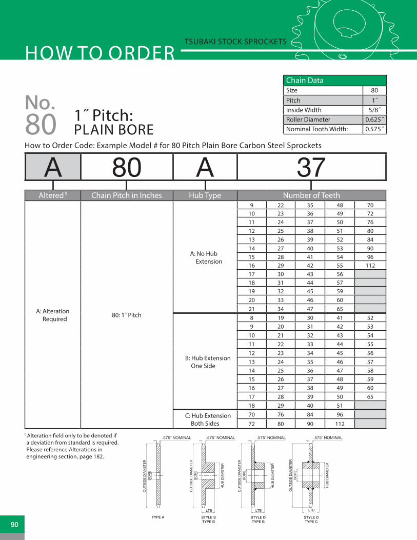
Chain DataSize 80Pitch 1˝Inside Width 5/8˝Roller Diameter 0.625˝Nominal Tooth Width: 0.575˝
HOW TO ORDERTSUBAKI STOCK SPROCKETS
A 80 A 37Altered !! Chain Pitch in Inches Hub Type Number of Teeth
A: Alteration Required
80: 1˝ Pitch
A: No Hub Extension
9 22 35 48 7010 23 36 49 7211 24 37 50 7612 25 38 51 8013 26 39 52 8414 27 40 53 9015 28 41 54 9616 29 42 55 11217 30 43 5618 31 44 5719 32 45 5920 33 46 6021 34 47 65
B: Hub Extension One Side
8 19 30 41 529 20 31 42 53
10 21 32 43 5411 22 33 44 5512 23 34 45 5613 24 35 46 5714 25 36 47 5815 26 37 48 5916 27 38 49 6017 28 39 50 6518 29 40 51
C: Hub Extension Both Sides
70 76 84 96
72 80 90 112
How to Order Code: Example Model # for 80 Pitch Plain Bore Carbon Steel Sprockets
No.1˝ Pitch: PLAIN BORE80
!! Alteration �eld only to be denoted if a deviation from standard is required. Please reference Alterations in engineering section, page 182.
TOOTH (NOMINAL) TOOTH (NOMINAL)TOOTH (NOMINAL)TOOTH (NOMINAL)
TYPE A STYLE DTYPE B
STYLE STYPE B
STYLE DTYPE C
OU
TSID
E DI
AMET
ER
OU
TSID
E DI
AMET
ERBO
RE
HU
B DI
AMET
ER
LTB
BORE
HU
B DI
AMET
ER
LTBLTB
OU
TSID
E DI
AMET
ERBO
RE
BORE
OU
TSID
E DI
AMET
ER
HU
B DI
AMET
ER
.575 NOMINAL .575 NOMINAL .575 NOMINAL .575 NOMINAL
90

PLAIN BORE SPROCKET DIMENSIONSNo. 80 Tsubaki Stock Sprockets
No. 80 Plain Bore Sprocket Dia. Type “A” Plain Bore Type “B” & “C” Plain Bore
No. Teeth
Outside Dia.
Pitch Dia.
Caliper Dia.
Plain Bore
Wt. Lbs.
Plain Bore
MAX Bore *
Hub Dia. LTB Hub
TypeHub Style
Wt. Lbs.
8 3.010 2.613 1.988 N/A N/A 1.000 1.000 1.938 ¨ 1.625 B S 1.409 3.350 2.924 2.254 0.938 0.80 1.000 1.313 2.250 ¨ 1.625 B S 1.60
10 3.680 3.236 2.611 0.938 1.00 1.000 1.500 2.563 ¨ 1.625 B S 2.2011 4.010 3.549 2.888 0.938 1.30 1.000 1.625 2.813 ¨ 1.625 B S 3.2012 4.330 3.864 3.239 0.938 1.50 1.000 1.875 3.125 ¨ 1.625 B S 3.4013 4.660 4.179 3.523 0.938 1.80 1.000 2.000 3.000 1.500 B S 3.5014 4.980 4.494 3.869 0.938 2.20 1.000 2.250 3.250 1.500 B S 4.1015 5.300 4.810 4.158 0.938 2.50 1.000 2.500 3.813 1.500 B S 5.3016 5.630 5.126 4.501 0.938 2.90 1.000 2.750 4.000 1.500 B S 5.9017 5.950 5.442 4.794 0.938 3.30 1.000 2.750 4.000 1.500 B S 6.6018 6.270 5.759 5.134 0.938 3.70 1.000 2.750 4.250 1.500 B S 7.3019 6.590 6.076 5.430 0.938 4.10 1.000 2.750 4.250 1.500 B S 7.8020 6.910 6.392 5.767 0.938 4.70 1.000 2.750 4.250 1.500 B S 8.4021 7.240 6.710 6.066 0.938 4.900 1.000 2.750 4.250 1.750 B S 9.4022 7.560 7.027 6.402 0.938 5.500 1.000 2.750 4.250 1.750 B S 10.0023 7.880 7.344 6.702 0.938 6.300 1.000 2.750 4.250 1.750 B S 10.7024 8.200 7.661 7.036 0.938 6.700 1.000 2.750 4.250 1.750 B S 11.3025 8.520 7.979 7.338 0.938 7.200 1.000 2.750 4.250 1.750 B S 11.9026 8.840 8.296 7.671 1.188 7.800 1.250 3.250 4.750 2.000 B D 14.3027 9.160 8.614 7.974 1.188 8.600 1.250 3.250 4.750 2.000 B D 15.4028 9.480 8.931 8.306 1.188 9.300 1.250 3.250 4.750 2.000 B D 16.0029 9.800 9.249 8.611 1.188 9.800 1.188 3.250 4.750 2.000 B D 17.1030 10.110 9.567 8.942 1.188 10.70 1.188 3.250 4.750 2.000 B D 17.4031 10.430 9.884 9.247 1.188 11.30 1.188 3.250 4.750 2.000 B D 18.7032 10.750 10.202 9.577 1.188 12.10 1.188 3.250 4.750 2.000 B D 19.5033 11.070 10.520 9.883 1.188 13.60 1.188 3.250 4.750 2.000 B D 19.6034 11.390 10.838 10.213 1.188 14.30 1.188 3.250 4.750 2.000 B D 21.3035 11.710 11.156 10.520 1.188 14.80 1.188 3.250 4.750 2.000 B D 22.1036 12.030 11.474 10.849 1.188 16.10 1.188 3.250 4.750 2.000 B D 23.1037 12.350 11.792 11.156 1.188 16.80 1.188 3.250 4.750 2.000 B D 23.8038 12.670 12.110 11.485 1.188 17.20 1.188 3.250 4.750 2.000 B D 24.7039 12.990 12.428 11.792 1.188 17.90 1.188 3.250 4.750 2.000 B D 25.6040 13.310 12.746 12.121 1.188 18.90 1.188 3.250 4.750 2.000 B D 26.7041 13.630 13.064 12.429 1.250 21.00 1.250 3.250 4.750 2.000 B D 27.8042 13.940 13.382 12.757 1.250 21.80 1.250 3.250 4.750 2.000 B D 28.7043 14.260 13.700 13.065 1.250 23.60 1.250 3.250 4.750 2.000 B D 29.4044 14.580 14.018 13.393 1.250 24.30 1.250 3.250 4.750 2.000 B D 29.9045 14.900 14.336 13.702 1.250 25.20 1.250 3.250 4.750 2.000 B D 31.4046 15.220 14.654 14.029 1.250 26.60 1.250 3.250 4.750 2.000 B D 33.1047 15.540 14.972 14.338 1.250 26.40 1.250 3.250 4.750 2.000 B D 34.0048 15.860 15.290 14.665 1.250 27.80 1.250 3.250 4.750 2.000 B D 35.5049 16.180 15.608 14.975 1.250 28.90 1.250 3.250 4.750 2.000 B D 35.8050 16.500 15.926 15.301 1.250 30.90 1.250 3.250 4.750 2.000 B D 37.3051 16.810 16.244 15.611 1.250 32.20 1.250 3.250 4.750 2.000 B D 38.5052 17.130 16.562 15.937 1.250 33.00 1.250 3.250 4.750 2.000 B D 39.4053 17.450 16.880 16.248 1.250 34.90 1.250 3.250 4.750 2.000 B D 41.3054 17.770 17.198 16.573 1.250 36.60 1.250 3.500 5.250 2.000 B D 44.7055 18.090 17.516 16.884 1.250 37.50 1.250 3.500 5.250 2.000 B D 45.6056 18.410 17.835 17.210 1.250 39.40 1.250 3.500 5.250 2.000 B D 47.5057 18.730 18.153 17.521 1.250 40.40 1.250 3.500 5.250 2.000 B D 48.5058 19.040 18.471 17.846 1.250 41.30 1.250 3.500 5.250 2.000 B D 50.5059 19.360 18.789 18.157 1.250 42.90 1.250 3.500 5.250 2.000 B D 52.1060 19.680 19.107 18.482 1.250 45.30 1.250 3.500 5.250 2.000 B D 54.5065 21.270 20.698 20.067 1.250 52.20 1.250 3.500 5.250 2.000 B D 61.8070 22.870 22.289 21.644 1.500 59.80 1.500 4.250 6.250 3.500 C D 75.7072 23.500 22.926 22.301 1.500 65.70 1.500 4.250 6.250 3.500 C D 81.4080 26.050 25.471 24.846 1.500 79.60 1.500 4.250 6.250 3.500 C D 89.9084 27.330 26.744 26.119 1.500 86.10 1.500 4.250 6.250 3.500 C D 99.2096 31.150 30.563 29.938 1.500 120.00 1.500 4.250 6.250 3.500 C D 117.00
112 36.240 35.655 35.030 1.500 166.00 1.500 4.250 6.250 3.500 C D 154.00
* Dimensions shown allow for standard keyway with set screw at 90 degrees¨ Has recessed groove in hub for chain clearance
All dimensions in inches unless noted.
91www.tsubaki.ca

HOW TO ORDERTSUBAKI STOCK SPROCKETS
Chain DataSize 80Pitch 1˝Inside Width 5/8˝Roller Diameter 0.625˝Nominal Tooth Width: 0.575˝
How to Order Code: Example Model # for 80 Pitch Finished Bore Carbon Steel Sprockets
80 B 60 F - 2R
No.1˝ Pitch: FINISHED BORE80
Chain Pitch in Inches Hub Type Number of Teeth Finished Bore Hub Bore**
80: 1˝ PitchB: Hub Extension One Side
9 24 39 54
F: Hub Extension Machined with keyway and two set screws
1 1" (1.000")10 25 40 55 1B 1-1/8" (1.125")11 26 41 56 1C 1-3/16" (1.188")12 27 42 57 1D 1-1/4" (1.250")13 28 43 58 1F 1-3/8" (1.375")14 29 44 59 1G: 1-7/16" (1.438")15 30 45 60 1H: 1-1/2" (1.500")16 31 46 1J 1-5/8" (1.625")
17 32 47 1L 1-3/4" (1.750")
18 33 48 1P 1-7/8" (1.875")
19 34 49 1R 1-15/16" (1.938")
20 35 50 2 2" (2.000")
21 36 51 2C 2-3/16" (2.188")
22 37 52 2G 2-7/16" (2.438")
23 38 53 2R 2-15/16" (2.938")
** Hub bore size should be selected from dimensional table on the following page. Bore sizes that are not listed for a given number of sprocket teeth may be available per request as Altered.
OU
TSID
EDI
AMET
ER
BORE
HU
BDI
AMET
ER
STYLE ETYPE B
LTB
TOOTH (NOMINAL)
STYLE STYPE B
LTB
TOOTH (NOMINAL)
OU
TSID
EDI
AMET
ER
BORE
HU
BDI
AMET
ER
.575 NOMINAL .575 NOMINAL
92

FINISHED BORE SPROCKET DIMENSIONSNo. 80 Tsubaki Stock Sprockets
No. 80 Finished Bore Sprocket Dia.
Type “F” Bored to Shaft Size (includes standard keyway and two set screws)
No. Teeth
Outside Dia.
Pitch Dia.
Caliper Dia. 1.
000˝
1.12
5˝
1.18
8˝
1.25
0˝
1.37
5˝
1.43
8˝
1.50
0˝
1.62
5˝
1.75
0˝
1.87
5˝
1.93
8˝
2.00
0˝
2.18
8˝
2.43
8˝
2.93
8˝
9 3.350 2.924 2.254 • • • •10 3.680 3.236 2.611 • • • •11 4.010 3.550 2.888 • • • • • • • • ¢
12 4.330 3.864 3.239 • • • • • • • • •13 4.660 4.179 3.523 • • • • • • • • • • • ¢ • ¢
14 4.980 4.494 3.869 • • • • • • • • • • ¢ • ¢ • ¢
15 5.300 4.810 4.158 • • • • • • • • • • • •16 5.630 5.126 4.501 • • • • • • • • • • •17 5.950 5.442 4.794 • • • • • • • • • • • •18 6.270 5.759 5.134 • • • • • • • • • • • •19 6.590 6.076 5.430 • • • • • • • • • • • •20 6.910 6.392 5.767 • • • • • • • • • • • •21 7.240 6.710 6.066 • • • • • • • • • • • •22 7.560 7.027 6.402 • • • • • • • • • • • •23 7.880 7.344 6.702 • • • • • • • • • • • •24 8.200 7.661 7.036 • • • • • • • • • • • •25 8.520 7.979 7.338 • • • • • • • • • • • •26 8.840 8.296 7.671 • • • • • • • • • • •27 9.160 8.614 7.974 • • • • • • • • • • •28 9.480 8.931 8.306 • • • • • • • • • • •29 9.800 9.249 8.611 • • • • • • • • • • •30 10.110 9.567 8.942 • • • • • • • • • • •31 10.430 9.884 9.247 • • • • • • • • • • •32 10.750 10.202 9.577 • • • • • • • • • • •33 11.070 10.520 9.883 • • • • • • • • • • •34 11.390 10.838 10.213 • • • • • • • • • • •35 11.710 11.156 10.520 • • • • • • • • • • •36 12.030 11.474 10.849 • • • • • • • • • • •37 12.350 11.792 11.156 • • • • • • • • • • •38 12.670 12.110 11.485 • • • • • • • • • • •39 12.990 12.428 11.792 • • • • • • • • • • •40 13.310 12.746 12.121 • • • • • • • • • • •41 13.630 13.064 12.429 • • • • • • • • • •42 13.940 13.382 12.757 • • • • • • • • • •43 14.260 13.700 13.065 • • • • • • • • • •44 14.580 14.018 13.393 • • • • • • • • • •45 14.900 14.336 13.702 • • • • • • • • • •46 15.220 14.654 14.029 • • • • • • • • • •47 15.540 14.972 14.338 • • • • • • • • • •48 15.860 15.290 14.665 • • • • • • • • • •49 16.180 15.608 14.975 • • • • • • • • • •50 16.500 15.926 15.301 • • • • • • • • • •51 16.810 16.244 15.611 • • • • • • • • • •52 17.130 16.562 15.937 • • • • • • • • • •53 17.450 16.880 16.248 • • • • • • • • • •54 17.770 17.198 16.573 • • • • • • • • • •55 18.090 17.516 16.884 • • • • • • • • • •56 18.410 17.835 17.210 • • • • • • • • • •57 18.730 18.153 17.521 • • • • • • • • • •58 19.040 18.471 17.846 • • • • • • • • • •59 19.360 18.789 18.157 • • • • • • • • • •60 19.680 19.107 18.482 • • • • • • • • • •
• Denotes stocking item ¢ Indicates ser screw at 90 degrees and 180 degrees from keyway
All dimensions in inches unless noted.
93www.tsubaki.ca

HOW TO ORDERTSUBAKI STOCK SPROCKETS
Chain DataSize 80SSPitch 1˝Inside Width 5/8˝Roller Diameter 0.625˝Nominal Tooth Width: 0.575˝
How to Order Code: Example Model # for 80 Pitch Plain Bore Stainless Steel Sprockets
!! Alteration field only to be denoted if a deviation from standard is required. Please reference Alterations in engineering section, page 182.
A 80 B 24 SS
No.1˝ Pitch: STAINLESS STEEL PLAIN BORE80
Altered !! Chain Pitch in Inches Hub Type: Number of Teeth* Material
A: Alteration Required
80: 1˝ PitchB: Hub
Extension One Side
10 13 16 20 24SS: 304 Stainless
Steel Construction11 14 18 22
12 15 19 23
B: Hub Extension One Side
94

STAINLESS STEEL SPROCKET DIMENSIONSNo. 80 Tsubaki Stock Sprockets
No. 80 Stainless Steel Sprocket Diameters Type “B” Plain Bore
No. Teeth
Outside Diameter
Pitch Diameter
Caliper Diameter
Plain Bore
MAX Bore *
Hub Dia. LTB Hub
StyleWt. Lbs.
10 3.680 3.236 2.611 1.000 1.500 2.563 ¨ 1.625 S 2.20
11 4.010 3.550 2.888 1.000 1.625 2.813 ¨ 1.625 S 3.20
12 4.330 3.864 3.239 1.000 1.875 3.125 ¨ 1.625 S 3.40
13 4.660 4.179 3.523 1.000 2.000 3.000 1.500 S 3.50
14 4.980 4.494 3.869 1.000 2.250 3.250 1.500 S 4.10
15 5.300 4.810 4.158 1.000 2.500 3.813 1.500 S 5.30
16 5.630 5.126 4.501 1.000 2.750 4.000 1.500 S 5.90
18 6.270 5.759 5.134 1.000 2.750 4.250 1.500 S 7.30
19 6.590 6.076 5.430 1.000 2.750 4.250 1.500 S 7.80
20 6.910 6.392 5.767 1.000 2.750 4.250 1.500 S 8.40
22 7.560 7.027 6.402 1.000 2.750 4.250 1.750 E 10.00
23 7.880 7.344 6.702 1.000 2.750 4.250 1.750 E 10.70
24 8.200 7.661 7.036 1.000 2.750 4.250 1.750 E 11.30
* Dimensions shown allow for standard keyway with set screw at 90 degrees¨ Has recessed groove in hub for chain clearance
LTBLTB
OU
TSID
EDI
AMET
ER
OU
TSID
EDI
AMET
ER
OU
TSID
EDI
AMET
ER
BORE
BORE
BORE
HU
BDI
AMET
ER
HU
BDI
AMET
ER
STYLE ETYPE B
STYLE STYPE B
TYPE A
TOOTH(NOMINAL)
TOOTH(NOMINAL)
TOOTH(NOMINAL)
LTB
OU
TSID
EDI
AMET
ER
BORE
HU
BDI
AMET
ER
STYLE DTYPE B
TOOTH(NOMINAL)
.575NOMINAL
.575NOMINAL
All dimensions in inches unless noted.
95www.tsubaki.ca

HOW TO ORDERTSUBAKI STOCK SPROCKETS
Chain DataSize 80-2, 80-3Pitch 1˝Inside Width 5/8˝Roller Diameter 0.625˝Nominal Tooth Width: 0.557˝
How to Order Code: Example Model # for 80 Pitch Multi-Strand Carbon Steel Sprockets
A D 80 B 25Altered !! Multi Chain Pitch in Inches Hub Type Number of Teeth
A: Alteration Required
D: Double Strand
80: 1˝ PitchB: Hub Extension One Side
Double Strand10 14 18 22 3011 15 19 23 3612 16 20 24 4513 17 21 25
T: Triple Strand
Triple Strand
11 15 19 23 36
12 16 20 24 45
13 17 21 25
14 18 22 30
No.1˝ Pitch: MULTI-STRAND80
!! Alteration field only to be denoted if a deviation from standard is required. Please reference Alterations in engineering section, page 182.
OU
TSID
EDI
AMET
ER
OU
TSID
EDI
AMET
ER
BORE
OU
TSID
EDI
AMET
ERBO
RE
BORE
HU
BDI
AMET
ER
HU
BDI
AMET
ER
HU
BDI
AMET
ER
OU
TSID
EDI
AMET
ERBO
RE
HU
BDI
AMET
ER
STYLE STYPE B
STYLE STYPE B
STYLE DTYPE B
DOUBLE STRAND DOUBLE STRAND TRIPLE STRAND TRIPLE STRAND
LTB
STYLE DTYPE B
LTB LTB LTB
TOOTH (NOMINAL)PLATE THICKNESS
TOOTH (NOMINAL)PLATE THICKNESS
PLATE T ICKNESS 1. 10
PLATE T ICKNESS 1. 10
PLATE T ICKNESS 2.8
PLATE T ICKNESS 2.8
.557 NOMINAL .557 NOMINAL .557 NOMINAL .557 NOMINAL
96

MULTI-STRAND SPROCKET DIMENSIONSNo. 80 Tsubaki Stock Sprockets
No. 80 Multi-Strand Sprocket Dia. Dimensional Data: Double Strand Sprockets
No. Teeth
Outside Diameter
Plain Bore
Hub Diameter LTB MAX Bore * Hub
Type Hub Style
Wt. Lbs.
10 3.680 1.000 2.563 ¨ 2.750 1.500 B S 3.5011 4.010 1.000 2.500 2.500 1.750 B S 4.0012 4.330 1.000 2.844 2.500 1.875 B S 5.1013 4.660 1.000 3.156 2.500 2.250 B S 6.3014 4.980 1.000 3.469 2.500 2.375 B S 7.6015 5.300 1.000 3.797 2.500 2.500 B S 9.0016 5.630 1.000 4.000 2.750 2.750 B S 11.0017 5.950 1.000 4.422 2.750 3.000 B S 13.2018 6.270 1.000 4.734 2.750 3.250 B S 15.0019 6.590 1.000 5.000 2.750 3.313 B S 17.0020 6.910 1.000 5.000 2.750 3.313 B S 18.2021 7.240 1.000 5.000 2.750 3.313 B S 19.5022 7.560 1.000 5.000 2.750 3.313 B S 21.0023 7.880 1.000 5.000 2.750 3.313 B S 22.8024 8.200 1.000 5.250 2.750 3.500 B S 25.1025 8.520 1.000 5.250 3.000 3.500 B S 28.3030 10.110 1.250 5.750 3.000 3.750 B S 39.5036 12.030 1.250 5.750 3.125 3.750 B D 54.2045 14.900 1.250 5.750 3.125 3.750 B D 73.50
No. 80 Multi-Strand Sprocket Dia. Dimensional Data: Triple Strand Sprockets
No. Teeth
Outside Diameter
Plain Bore
Hub Diameter LTB MAX Bore * Hub
Type Hub Style
Wt. Lbs.
11 4.010 1.000 2.500 3.625 1.750 B S 5.9012 4.330 1.000 2.844 3.625 1.875 B S 7.5013 4.660 1.000 3.156 3.625 2.250 B S 9.2014 4.980 1.000 3.469 3.625 2.375 B S 11.0015 5.300 1.000 3.797 3.625 2.500 B S 13.1016 5.630 1.000 4.000 3.875 2.750 B S 15.8017 5.950 1.000 4.422 3.875 3.000 B S 18.6018 6.270 1.000 4.734 3.875 3.250 B S 21.2019 6.590 1.000 5.000 3.875 3.313 B S 23.7020 6.910 1.000 5.000 3.875 3.313 B S 26.0021 7.240 1.000 5.000 3.875 3.313 B S 28.4022 7.560 1.000 5.000 3.875 3.313 B S 31.0023 7.880 1.000 5.000 3.875 3.313 B S 33.6024 8.200 1.000 5.250 3.875 3.500 B S 37.1025 8.520 1.000 5.250 3.875 3.500 B S 40.1030 10.110 1.250 5.750 4.250 3.750 B S 54.5036 12.030 1.250 5.750 4.250 3.750 B D 83.9045 14.900 1.250 6.000 4.500 3.813 B D 92.40
* Dimensions shown allow for standard keyway with set screw at 90 degrees
* Dimensions shown allow for standard keyway with set screw at 90 degrees¨ Has recessed groove in hub for chain clearance
All dimensions in inches unless noted.
All dimensions in inches unless noted.
97www.tsubaki.ca

HOW TO ORDERTSUBAKI STOCK SPROCKETS
Chain DataSize 80Pitch 1˝Inside Width 5/8˝Roller Diameter 0.625˝Nominal Tooth Width: 0.575˝
!! Alteration field only to be denoted if a deviation from standard is required. Please reference Alterations in engineering section, page 182.
!! Alteration field only to be denoted if a deviation from standard is required. Please reference Alterations in engineering section, page 182.
A DS 80 A 19
A DS 80 A TL 19
Altered !! Multi Chain Pitch in Inches Hub Type Number of Teeth
A: Alteration Required
DS: Double Single 80: 1˝ Pitch A: No Hub
Extension
13 17 2114 18 2215 1916 20
Altered !! Multi Chain Pitch in Inches Hub Type TAPER-LOCK® Number of Teeth
A: Alteration Required
DS: Double Single
80: 1˝ Pitch A: No Hub Extension
TAPER-LOCK® hub with set
screws
17 21
18 23
19
20
How to Order Code: Example Model # for 80 Pitch Double Single Carbon Steel Sprockets
How to Order Code: Example Model # for 80 Pitch Double Single TAPER-LOCK® Carbon Steel Sprockets
No.1˝ Pitch: DOUBLE SINGLE80
TAPER-LOCK® bushing is not included with the sprocket. They are to be ordered separately. Please refer to the table below for general guidelines. Speci�c details are found in the Bushing Section of this catalog beginning on page 164.
TAPER-LOCK® BushingsBushing # Bore Range
2517 0.500 - 2.688˝3020 0.875 - 3.250˝
TAPER-LOCK® is a registered trademark of Rockwell Automation.98

No. 80 Tsubaki Stock Sprockets
DOUBLE SINGLE SPROCKET DIMENSIONS
No. 80 Double Single Sprocket Diameters Dimensional Data: Double Single Sprockets
No. Teeth Outside Dia. Plain Bore LTB C D MAX Bore * Weight Lbs.
13 4.660 1.000 2.188 1.625 3.016 2.000 6.50
14 4.980 1.000 2.188 1.625 3.344 2.250 7.70
15 5.300 1.000 2.188 1.625 3.813 2.375 9.10
16 5.630 1.000 2.188 1.625 4.000 2.688 9.50
17 5.950 1.000 2.188 1.625 4.313 2.813 10.80
18 6.270 1.000 2.188 1.625 4.641 3.125 12.10
19 6.590 1.000 2.188 1.625 4.953 3.250 12.80
20 6.910 1.000 2.188 1.625 5.281 3.500 14.00
21 7.240 1.000 2.188 1.625 5.594 3.750 16.50
22 7.560 1.000 2.188 1.625 5.922 3.750 18.40
No. 80 Double Single TAPER-LOCK® Sprocket Diameters Dimensional Data: Double Single TAPER-LOCK® Sprockets
No. Teeth Outside Dia. Bushing # LTB C D MAX Bore * Weight Lbs.
17 5.950 2517 2.188 1.625 4.313 2.688 7.60
18 6.270 2517 2.188 1.625 4.641 2.688 8.70
19 6.590 3020 2.188 1.625 4.953 3.250 9.70
20 6.910 3020 2.188 1.625 5.281 3.250 10.00
21 7.240 3020 2.188 1.625 5.594 3.250 12.00
23 7.880 3020 2.188 1.625 6.234 3.250 14.50
BORE
D
D
OU
TSID
EDI
AMET
ER
OU
TSID
EDI
AMET
ER
STOCK BOREDOUBLE SINGLE
TAPER-LOCK®
DOUBLE SINGLE
LTB
C C
LTB
.575 NOMINAL
BORE
D
D
OU
TSID
EDI
AMET
ER
OU
TSID
EDI
AMET
ER
STOCK BOREDOUBLE SINGLE
TAPER-LOCK®
DOUBLE SINGLE
LTB
C C
LTB
.575 NOMINAL
* Dimensions shown allow for standard keyway with set screw at 90 degrees
* Please reference TAPER-LOCK® bushing dimension table on page 165 for specific information on MAX Bore and keyway data.
All dimensions in inches unless noted.
All dimensions in inches unless noted.
99www.tsubaki.ca

HOW TO ORDERTSUBAKI STOCK SPROCKETS
Chain DataSize 80Pitch 1˝Inside Width 5/8˝Roller Diameter 0.625˝Nominal Tooth Width: 0.575˝
How to Order Code: Example Model # for 80 Pitch TAPER-LOCK® Carbon Steel Sprockets
!! Alteration field only to be denoted if a deviation from standard is required. Please reference Alterations in engineering section, page 182.
A 80 B TL 25Altered !! Chain Pitch in Inches Hub Type TAPER-LOCK® Number of Teeth
A: Alteration Required 80: 1˝ Pitch B: Hub Extension
One SideTAPER-LOCK® hub
with set screws
10 16 22 28 4511 17 23 30 4812 18 24 32 5413 19 25 35 6014 20 26 36 7015 21 27 40 80
No.1˝ Pitch: TAPER-LOCK®80
STYLE STYPE B
LTB
TOOTH (NOMINAL)
OU
TSID
EDI
AMET
ER
OU
TSID
EDI
AMET
ER
HU
BDI
AMET
ERLTB
STYLE STYPE B
PLATE THICKNESSTOOTH (NOMINAL)
OU
TSID
EDI
AMET
ER
HU
BDI
AMET
ER
HU
BDI
AMET
ER
STYLE ETYPE B
LTB
TOOTH (NOMINAL)
SINGLE “TAPER-LOCK” STYLE DOUBLE “TAPER-LOCK” STYLE.575NOMINAL
.575NOMINAL
TAPER-LOCK® bushing is not included with the sprocket. They are to be ordered separately. Please refer to the table below for general guidelines. Specific details are found in the Bushing Section of this catalog beginning on page 164.
TAPER-LOCK® BushingsBushing # Bore Range
1215 0.500 - 1.250˝1615 0.500 - 1.688˝2012 0.500 - 2.125˝2517 0.500 - 2.688˝3020 0.875 - 3.250˝
TAPER-LOCK® is a registered trademark of Rockwell Automation.100

TAPER-LOCK® SPROCKET DIMENSIONSNo. 80 Tsubaki Stock Sprockets
No. 80 TAPER-LOCK® Sprockets Dimensional Data TAPER-LOCK® Sprockets
No. Teeth
Outside Diameter Bushing # Hub
Diameter LTB MAX Bore * Hub Style Weight Lbs.
10 3.680 1215 2.375 ¨ 1.500 1.250 S 1.10
11 4.010 1215 2.469 ¨ 1.500 1.250 S 1.50
12 4.330 1615 3.000 ¨ 1.500 1.688 S 1.80
13 4.660 1615 3.000 1.500 1.688 S 2.30
14 4.980 1615 3.343 1.500 1.688 S 2.50
15 5.300 1615 3.500 1.500 1.688 S 2.70
16 5.630 2012 4.000 1.250 2.125 S 2.80
17 5.950 2012 4.000 1.250 2.125 E 3.10
18 6.270 2012 3.563 1.250 2.125 E 3.60
19 6.590 2012 3.563 1.250 2.125 E 4.10
20 6.910 2517 4.250 1.750 2.688 E 5.50
21 7.240 2517 4.250 1.750 2.688 E 6.00
22 7.560 2517 4.250 1.750 2.688 E 6.50
23 7.880 2517 4.250 1.750 2.688 E 7.00
24 8.200 2517 4.250 1.750 2.688 E 7.50
25 8.520 2517 4.250 1.750 2.688 E 8.10
26 8.840 2517 4.250 1.750 2.688 E 8.80
27 9.160 2517 4.250 1.750 2.688 E 9.00
28 9.480 2517 4.250 1.750 2.688 E 9.50
30 10.110 2517 4.250 1.750 2.688 E 11.50
32 10.750 2517 4.250 1.750 2.688 E 12.00
35 11.710 2517 4.250 1.750 2.688 E 15.20
36 12.030 2517 4.250 1.750 2.688 E 17.00
40 13.310 2517 4.250 1.750 2.688 E 21.00
45 14.900 2517 4.250 1.750 2.688 E 26.50
48 15.860 2517 4.250 1.750 2.688 E 29.50
54 17.770 2517 4.250 1.750 2.688 E 38.50
60 19.680 2517 4.250 1.750 2.688 E 45.20
70 22.870 3020 5.250 2.000 3.250 E 52.30
80 26.050 3020 5.250 2.000 3.250 E 69.20
* Please reference TAPER-LOCK® bushing dimension table on page 165 for specific information on MAX Bore and keyway data.¨ Has recessed groove in hub for chain clearance
All dimensions in inches unless noted.
101www.tsubaki.ca

HOW TO ORDERTSUBAKI STOCK SPROCKETS
Chain DataSize 80-2Pitch 1˝Inside Width 5/8˝Roller Diameter 0.625˝Nominal Tooth Width: 0.557˝
How to Order Code: Example Model # for 80 Pitch Multi-Strand TAPER-LOCK® Carbon Steel Sprockets
!! Alteration field only to be denoted if a deviation from standard is required. Please reference Alterations in engineering section, page 182.
A D 80 B TL 19Altered !! Multi-Strand Chain Pitch
in Inches Hub Type TAPER-LOCK® Number of Teeth
A: Alteration Required D: Double Strand 80: 1˝ Pitch
A: No Hub Extension
TAPER-LOCK® hub with set screws
A Style
13 15 17
14 16 18
B: Hub Extension One Side
B Style
19 21
20 25
C: Hub Extension Both Sides
C Style
30 42 52
36 45 60
No.1˝ Pitch: MULTI-STRAND TAPER-LOCK®80
TAPER-LOCK® bushing is not included with the sprocket. They are to be ordered separately. Please refer to the table below for general guidelines. Speci�c details are found in the Bushing Section of this catalog beginning on page 164.
TAPER-LOCK® BushingsBushing # Bore Range
1615 0.500 - 1.688˝2012 0.500 - 2.125˝2517 0.500 - 2.688˝3020 0.875 - 3.250˝
TAPER-LOCK® is a registered trademark of Rockwell Automation.102

MULTI-STRAND TAPER-LOCK® SPROCKET DIMENSIONSNo. 80
Tsubaki Stock Sprockets
No. 80 Multi-Strand TAPER-LOCK® Sprockets Dimensional Data Multi-Strand TAPER-LOCK® Sprockets
No. Teeth
Outside Diameter Bushing # Hub
Diameter LTB MAX Bore * Hub Type Hub Style Weight Lbs.
13 4.660 1615 N/A 1.500 1.688 A S 3.40
14 4.980 2012 N/A 1.250 2.125 A S 3.50
15 5.300 2012 N/A 1.250 2.125 A S 4.30
16 5.630 2517 3.125 1.750 2.688 A S 3.80
17 5.950 2517 3.125 1.750 2.688 A S 5.10
18 6.270 2517 3.125 1.750 2.688 A S 6.40
19 6.590 3020 5.000 2.000 3.250 B S 5.60
20 6.910 3020 5.250 2.000 3.250 B S 7.10
21 7.240 3020 5.563 2.000 3.250 B S 8.90
25 8.520 3020 6.875 2.000 3.250 B S 16.50
30 10.110 3020 5.250 2.000 3.250 C S 25.10
36 12.030 3020 5.250 2.000 3.250 C S 39.40
42 13.940 3020 5.250 2.000 3.250 C S 36.40
45 14.900 3020 5.250 2.000 3.250 C S 41.40
52 17.130 3020 5.250 2.000 3.250 C W 56.20
60 19.680 3020 5.250 2.000 3.250 C W 66.30
PLATE THICKNESS 1.710˝.557 ˝ NOMINAL.557 ˝ NOMINAL
PLATE THICKNESS 1.710˝
OU
TSID
E DI
AMET
ER
HU
B DI
AMET
ER
LTB
.557 ˝ NOMINAL
PLATE THICKNESS 1.710˝
LTB
OU
TSID
E DI
AMET
ER
OU
TSID
E DI
AMET
ER
HU
B DI
AMET
ER
OU
TSID
E DI
AMET
ER
HU
B DI
AMET
ER
LTB
PLATE THICKNESS 1.710˝.557 ˝ NOMINAL
STYLE STYPE A
STYLE STYPE B
LTB
STYLE WTYPE C
STYLE STYPE C
* Please reference TAPER-LOCK® bushing dimension table on page 165 for specific information on MAX Bore and keyway data.
All dimensions in inches unless noted.
103www.tsubaki.ca

HOW TO ORDERTSUBAKI STOCK SPROCKETS
Chain DataSize 80Pitch 1˝Inside Width 5/8˝Roller Diameter 0.625˝Nominal Tooth Width: 0.575˝
A 80 SF 21How to Order Code: Example Model # for 80 Pitch QD® Carbon Steel Sprockets
Altered !! Chain Pitch in Inches QD® Hub Type Number of Teeth
A: Alteration Required 80: 1˝ Pitch
SH: QD® Hub 11 - 12 tooth sprocket
11
12
SDS: QD® Hub 13 - 14 tooth sprocket
13
14
SK: QD® Hub 15 - 19 tooth sprocket
15 18
16 19
17
SF: QD® Hub 20 - 60 tooth sprocket
20 24 28 36 48
21 25 30 40 54
22 26 32 42 60
23 27 35 45
No.80 1˝ Pitch: QD®
!! Alteration field only to be denoted if a deviation from standard is required. Please reference Alterations in engineering section, page 182.
QD® bushing is not included with the sprocket. They are to be ordered separately. Please refer to the table below for general guidelines. Specific details are found in the Bushing Section of this catalog beginning on page 170.
QD® BushingsBushing # Bore Range
SH 0.500 - 1.688˝SDS 0.500 - 2.000˝SK 0.500 - 2.625˝SF 0.500 - 2.938˝
QD® is a registered trademark of, and is used under license agreement from Emerson Electric Co.104

QD® SPROCKET DIMENSIONSNo. 80 Tsubaki Stock Sprockets
No. 80 QD® Sprockets Dimensional Data QD® Sprockets
No. Teeth
Outside Dia.
QD® Bushing #
MAX Bore *
Hub Dia. LTB X Y L F Hub
TypeHub Style
Weight Lbs.
11 4.010 SH 1.688 2.688 0.813 1.437 1.437 0.656 2.688 B S 1.00
12 4.330 SH 1.688 2.750 0.813 1.437 1.437 0.656 2.688 B S 1.40
13 4.660 SDS 2.000 3.188 0.750 1.500 1.500 0.734 3.188 B S 1.50
14 4.980 SDS 2.000 3.375 0.750 1.500 1.500 0.734 3.188 B S 1.80
15 5.300 SK 2.625 3.875 1.250 2.125 2.125 1.297 3.875 B S 2.50
16 5.630 SK 2.625 4.125 1.250 2.125 2.125 1.297 3.875 B S 3.10
17 5.950 SK 2.625 4.375 1.250 2.125 2.125 1.297 3.875 B S 3.50
18 6.270 SK 2.625 4.375 1.250 2.125 2.125 1.297 3.875 B S 3.90
19 6.590 SK 2.625 4.375 1.250 2.125 2.125 1.297 3.875 B S 4.40
20 6.910 SF 2.938 5.000 1.250 2.250 2.250 1.422 4.625 B S 5.30
21 7.240 SF 2.938 5.000 1.250 2.250 2.250 1.422 4.625 B S 5.70
22 7.560 SF 2.938 5.000 1.250 2.250 2.250 1.422 4.625 B S 6.30
23 7.880 SF 2.938 5.000 1.250 2.250 2.250 1.422 4.625 B E 6.80
24 8.200 SF 2.938 5.000 1.250 2.250 2.250 1.422 4.625 B E 7.50
25 8.520 SF 2.938 5.000 1.250 2.250 2.250 1.422 4.625 B E 8.00
26 8.840 SF 2.938 5.000 1.250 2.250 2.250 1.422 4.625 B E 8.60
27 9.160 SF 2.938 5.000 1.250 2.250 2.250 1.422 4.625 B E 9.40
28 9.480 SF 2.938 5.000 1.250 2.250 2.250 1.422 4.625 B E 10.20
30 10.110 SF 2.938 5.000 1.250 2.250 2.250 1.422 4.625 B E 11.30
32 10.750 SF 2.938 5.000 1.250 2.250 2.250 1.422 4.625 B E 13.00
33 11.070 SF 2.938 5.000 1.250 2.250 2.250 1.422 4.625 B E 13.50
34 11.390 SF 2.938 5.000 1.250 2.250 2.250 1.422 4.625 B E 14.10
35 11.710 SF 2.938 5.000 1.250 2.250 2.250 1.422 4.625 B E 15.50
36 12.030 SF 2.938 5.000 1.250 2.250 2.250 1.422 4.625 B E 16.90
40 13.310 SF 2.938 5.000 1.250 2.250 2.250 1.422 4.625 B E 20.60
42 13.940 SF 2.938 5.000 1.250 2.250 2.250 1.422 4.625 B E 22.40
45 14.900 SF 2.938 5.000 1.250 2.250 2.250 1.422 4.625 B E 25.10
48 15.860 SF 2.938 5.000 1.250 2.250 2.250 1.422 4.625 B E 28.60
54 17.770 SF 2.938 5.000 1.250 2.250 2.250 1.422 4.625 B E 36.80
60 19.680 SF 2.938 5.000 1.250 2.250 2.250 1.422 4.625 B E 45.80
STYLE STYPE B
X
L
YLTB
OU
TSID
EDI
AMET
ER
HU
BDI
AMET
ER
Y Y
HU
BDI
AMET
ER
OU
TSID
EDI
AMET
ER
HU
BDI
AMET
ERO
UTS
IDE
DIAM
ETER
F F F
STYLE ETYPE B
STYLE ETYPE C
X X
L
L
LTB LTBTOOTH(NOMINAL)
TOOTH(NOMINAL) TOOTH
(NOMINAL).575NOMINAL
.575NOMINAL
* Please reference QD® bushing dimension table on page 171 for specific information on MAX Bore and keyway data.
All dimensions in inches unless noted.
105www.tsubaki.ca

100
HOW TO ORDERTSUBAKI STOCK SPROCKETS
Chain DataSize 100Pitch 1 1/4˝Inside Width 3/4˝Roller Diameter 0.750˝Nominal Tooth Width: 0.692˝
A 100 B 36Altered !! Chain Pitch in Inches Hub Type Number of Teeth
A: Alteration Required
100: 1¼˝ Pitch
A: No Hub Extension
8 16 24 36 729 17 25 40 80
10 18 26 42 8411 19 27 45 9012 20 28 48 9613 21 30 5414 22 32 6015 23 35 70
B: Hub Extension One Side
8 16 24 369 17 25 40
10 18 26 4211 19 27 4512 20 28 4813 21 3014 22 3215 23 35
C: Hub Extension Both Sides
54 72 9060 80 9670 84
How to Order Code: Example Model # for 100 Pitch Plain Bore Carbon Steel Sprockets
No.1¼˝ Pitch: PLAIN BORE
!! Alteration �eld only to be denoted if a deviation from standard is required. Please reference Alterations in engineering section, page 182.
TOOTH (NOMINAL) TOOTH (NOMINAL)TOOTH (NOMINAL)TOOTH (NOMINAL)
TYPE A STYLE DTYPE B
STYLE STYPE B
STYLE DTYPE C
OU
TSID
E DI
AMET
ER
OU
TSID
E DI
AMET
ERBO
RE
HU
B DI
AMET
ER
LTB
BORE
HU
B DI
AMET
ER
LTBLTB
OU
TSID
E DI
AMET
ERBO
RE
BORE
OU
TSID
E DI
AMET
ER
HU
B DI
AMET
ER
.692 NOMINAL .692 NOMINAL .692 NOMINAL .692 NOMINAL
106

PLAIN BORE SPROCKET DIMENSIONSNo. 100 Tsubaki Stock Sprockets
No. 100 Plain Bore Sprocket Dia. Type “A” Plain Bore Type “B” & “C” Plain Bore
No. Teeth
Outside Dia.
Pitch Dia.
Caliper Dia.
Plain Bore
Wt. Lbs.
Plain Bore
MAX Bore *
Hub Dia. LTB Hub
TypeHub Style
Wt. Lbs.
8 3.770 3.266 2.516 1.000 1.40 1.000 1.250 2.438 ¨ 1.875 B S 2.30
9 4.180 3.655 2.849 1.000 1.60 1.000 1.625 2.813 ¨ 1.875 B S 3.20
10 4.600 4.045 3.295 1.000 2.00 1.000 1.875 3.250 ¨ 1.875 B S 4.10
11 5.010 4.438 3.642 1.250 2.50 1.000 2.250 3.563 ¨ 1.875 B S 5.30
12 5.420 4.830 4.080 1.250 3.00 1.000 2.250 4.000 ¨ 1.875 B S 6.40
13 5.820 5.224 4.435 1.250 3.50 1.000 2.375 3.875 1.625 B S 6.50
14 6.230 5.618 4.868 1.250 4.10 1.250 2.750 4.188 1.625 B S 7.40
15 6.630 6.013 5.229 1.250 4.70 1.250 3.000 4.500 1.750 B D 9.20
16 7.030 6.408 5.658 1.250 5.40 1.313 3.000 4.500 1.750 B D 9.90
17 7.440 6.803 6.024 1.250 6.10 1.313 3.000 4.500 1.750 B D 10.80
18 7.840 7.199 6.449 1.250 7.00 1.313 3.000 4.500 1.750 B D 11.50
19 8.240 7.595 6.819 1.250 7.80 1.313 3.000 4.500 2.000 B D 13.10
20 8.640 7.990 7.240 1.250 8.80 1.313 3.000 4.500 2.000 B D 14.20
21 9.040 8.388 7.613 1.250 9.80 1.313 3.000 4.500 2.000 B D 15.30
22 9.440 8.784 8.034 1.250 10.50 1.313 3.000 4.500 2.000 B D 16.10
23 9.840 9.180 8.409 1.250 11.80 1.250 3.000 4.500 2.000 B D 17.20
24 10.250 9.576 8.826 1.250 12.80 1.250 3.000 4.500 2.000 B D 19.20
25 10.660 9.974 9.204 1.250 13.90 1.250 3.000 4.500 2.000 B D 19.50
26 11.050 10.370 9.620 1.250 15.00 1.250 3.313 5.000 2.000 B D 21.70
27 11.440 10.768 9.999 1.250 16.00 1.250 3.313 5.000 2.000 B D 23.00
28 11.840 11.164 10.414 1.250 17.40 1.250 3.313 5.000 2.000 B D 24.40
30 12.640 11.959 11.209 1.250 20.10 1.250 3.313 5.000 2.000 B D 26.90
32 13.440 12.753 12.003 1.250 22.60 1.250 3.313 5.000 2.000 B D 29.80
35 14.640 13.945 13.181 1.250 27.20 1.250 3.313 5.000 2.500 B D 36.90
36 15.040 14.343 13.593 1.250 30.00 1.250 3.313 5.000 2.500 B D 38.60
40 16.630 15.933 15.183 1.250 36.00 1.250 3.313 5.000 2.500 B D 46.90
42 17.430 16.728 15.978 1.250 40.00 1.250 3.313 5.000 2.500 B D 50.40
45 18.630 17.920 17.159 1.500 47.00 1.500 3.313 5.000 2.500 B D 54.00
48 19.820 19.113 18.363 1.500 54.00 1.500 4.000 6.000 2.500 B D 66.00
54 22.210 21.498 20.748 1.500 68.00 1.500 4.000 6.000 3.250 C D 78.00
60 24.600 23.884 23.134 1.500 80.00 1.500 4.000 6.000 3.250 C D 89.00
70 28.580 27.861 27.111 1.500 113.00 1.500 5.250 7.000 3.750 C D 125.00
72 29.380 28.657 27.908 1.500 119.00 1.500 5.250 7.000 3.750 C D 134.00
80 32.570 31.839 31.089 1.500 146.00 1.500 5.250 7.000 3.750 C D 151.00
84 34.160 33.430 32.680 1.500 162.00 1.500 5.250 7.000 3.750 C D 170.00
90 36.550 35.817 35.068 1.500 193.00 1.500 5.250 7.000 3.750 C D 184.00
96 38.930 38.204 37.454 1.500 215.00 1.500 5.250 7.000 4.500 C D 203.00
* Dimensions shown allow for standard keyway with set screw at 90 degrees¨ Has recessed groove in hub for chain clearance
All dimensions in inches unless noted.
107www.tsubaki.ca
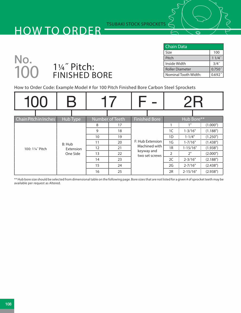
HOW TO ORDERTSUBAKI STOCK SPROCKETS
Chain DataSize 100Pitch 1 1/4˝Inside Width 3/4˝Roller Diameter 0.750˝Nominal Tooth Width: 0.692˝
How to Order Code: Example Model # for 100 Pitch Finished Bore Carbon Steel Sprockets
100 B 17 F - 2RChain Pitch in Inches Hub Type Number of Teeth Finished Bore Hub Bore**
100: 1¼˝ PitchB: Hub Extension One Side
8 17
F: Hub Extension Machined with keyway and two set screws
1 1" (1.000")9 18 1C 1-3/16" (1.188")
10 19 1D 1-1/4" (1.250")11 20 1G 1-7/16" (1.438")12 21 1R 1-15/16" (1.938")13 22 2 2" (2.000")14 23 2C 2-3/16" (2.188")15 24 2G 2-7/16" (2.438")
16 25 2R 2-15/16" (2.938")
** Hub bore size should be selected from dimensional table on the following page. Bore sizes that are not listed for a given # of sprocket teeth may be available per request as Altered.
100No.
1¼˝ Pitch: FINISHED BORE
108

FINISHED BORE SPROCKET DIMENSIONSNo. 100 Tsubaki Stock Sprockets
No. 100 Finished Bore Sprocket Dia.
Type “F” Bored to Shaft Size (includes standard keyway and two set screws)
No. Teeth
Outside Dia.
Pitch Dia.
Caliper Dia. 1.
000˝
1.18
8˝
1.25
0˝
1.43
8˝
1.93
8˝
2.00
0˝
2.18
8˝
2.43
8˝
2.93
8˝
8 3.770 3.266 2.516 • • •
9 4.180 3.655 2.849 • • • •
10 4.600 4.045 3.295 • • • •
11 5.010 4.438 3.642 • • • • • • •
12 5.420 4.830 4.080 • • • • • • •
13 5.820 5.224 4.435 • • • • • • •
14 6.230 5.618 4.868 • • • • •
15 6.630 6.013 5.229 • • • • •
16 7.030 6.408 5.658 • • • • • •
17 7.440 6.803 6.024 • • • • • •
18 7.840 7.199 6.449 • • • • • •
19 8.240 7.595 6.819 • • • • • •
20 8.640 7.990 7.240 • • • • • •
21 9.040 8.388 7.613 • • • • • •
22 9.440 8.784 8.034 • • • • • •
23 9.840 9.180 8.409 • • • • • •
24 10.250 9.576 8.826 • • • • • •
25 10.660 9.974 9.204 • • • • • •
OU
TSID
EDI
AMET
ER
BORE
HU
BDI
AMET
ER
STYLE DTYPE B
LTB
TOOTH (NOMINAL)
STYLE STYPE B
LTB
TOOTH (NOMINAL)
OU
TSID
EDI
AMET
ER
BORE
HU
BDI
AMET
ER
.692 NOMINAL .692 NOMINAL
• Denotes stocking item
All dimensions in inches unless noted.
109www.tsubaki.ca

HOW TO ORDERTSUBAKI STOCK SPROCKETS
How to Order Code: Example Model # for 100 Pitch Multi-Strand Carbon Steel Sprockets
A D 100 B 25Altered !! Multi Chain Pitch in Inches Hub Type Number of Teeth
A: Alteration Required
D: Double Strand
100: 1¼˝ PitchB: Hub Extension One Side
Double Strand9 14 19 24 35
10 15 20 25 3611 16 21 26
12 17 22 30
13 18 23 32
T: Triple Strand
Triple Strand
12 16 20 2413 17 21 2514 18 22 2615 19 23 30
!! Alteration field only to be denoted if a deviation from standard is required. Please reference Alterations in engineering section, page 182.
OU
TSID
EDI
AMET
ER
OU
TSID
EDI
AMET
ER
BORE
OU
TSID
EDI
AMET
ERBO
RE
BORE
HU
BDI
AMET
ER
HU
BDI
AMET
ER
HU
BDI
AMET
ER
OU
TSID
EDI
AMET
ERBO
RE
HU
BDI
AMET
ER
STYLE STYPE B
STYLE STYPE B
STYLE DTYPE B
DOUBLE STRAND DOUBLE STRAND TRIPLE STRAND TRIPLE STRAND
LTB
STYLE DTYPE B
LTB LTB LTB
TOOTH (NOMINAL)PLATE THICKNESS
TOOTH (NOMINAL)PLATE THICKNESS
PLATE T ICKNESS 2.0
PLATE T ICKNESS 2.0
PLATE T ICKNESS .485
PLATE T ICKNESS .485
.669 NOMINAL .669 NOMINAL .669 NOMINAL .669 NOMINAL
100No.
1¼˝ Pitch: MULTI-STRAND
Chain DataSize 100-2, 100-3Pitch 1 1/4˝Inside Width 3/4˝Roller Diameter 0.750˝Nominal Tooth Width: 0.669˝
110

MULTI-STRAND SPROCKET DIMENSIONSNo. 100 Tsubaki Stock Sprockets
No. 100 Multi-Strand Sprocket Dia. Dimensional Data: Double Strand Sprockets
No. Teeth
Outside Diameter
Plain Bore
Hub Diameter LTB MAX
Bore * Hub Type
Hub Style
Weight Lbs.
9 4.180 1.000 2.375 2.875 1.625 B S 4.6010 4.600 1.000 2.375 2.875 1.875 B S 6.2011 5.010 1.000 3.125 2.875 2.125 B S 7.9012 5.420 1.125 3.375 2.875 2.250 B S 9.3013 5.820 1.125 3.813 2.875 2.500 B S 11.4014 6.230 1.125 4.188 2.875 2.750 B S 13.6015 6.630 1.250 4.625 3.125 3.125 B S 17.1016 7.030 1.250 5.000 3.125 3.313 B S 20.1017 7.440 1.250 5.250 3.125 3.500 B S 23.1018 7.840 1.250 5.250 3.125 3.500 B S 25.4019 8.240 1.250 5.500 3.375 3.750 B S 29.6020 8.640 1.250 5.500 3.375 3.750 B S 32.4021 9.040 1.250 5.500 3.375 3.750 B S 35.3022 9.440 1.250 5.500 3.375 3.750 B D 38.4023 9.840 1.250 5.500 3.375 3.750 B D 41.3024 10.250 1.250 5.750 3.375 3.750 B D 45.1025 10.660 1.250 5.750 3.375 3.750 B D 48.5026 11.050 1.500 5.750 3.375 3.750 B D 51.5030 12.640 1.500 5.750 3.375 3.750 B D 65.0032 13.440 1.500 5.750 3.375 3.750 B D 69.0035 14.640 1.500 6.000 4.250 3.813 B D 75.0036 15.038 1.500 6.000 4.500 4.000 B D 90.80
No. 100 Multi-Strand Sprocket Dia. Dimensional Data: Triple Strand SprocketsNo.
TeethOutside
DiameterPlain Bore
Hub Diameter LTB MAX
Bore * Hub Type
Hub Style
Weight Lbs.
12 5.420 1.125 3.375 4.250 2.250 B S 13.7013 5.820 1.125 3.813 4.250 2.500 B S 16.9014 6.230 1.125 4.188 4.250 2.750 B S 20.2015 6.630 1.250 4.625 4.500 3.125 B S 25.0016 7.030 1.250 5.000 4.500 3.313 B S 29.3017 7.440 1.250 5.250 4.500 3.500 B S 33.8018 7.840 1.250 5.250 4.750 3.500 B S 38.6019 8.240 1.250 5.500 4.750 3.750 B D 43.3020 8.640 1.250 5.500 4.750 3.750 B D 47.9021 9.040 1.250 5.500 4.750 3.750 B D 52.3022 9.440 1.250 5.500 4.750 3.750 B D 57.5023 9.840 1.250 5.500 4.750 3.750 B D 62.5024 10.250 1.250 5.750 4.750 3.750 B D 69.0025 10.660 1.250 5.750 4.750 3.750 B D 73.0026 11.050 1.500 5.750 4.750 3.813 B D 79.0030 12.640 1.500 5.750 4.750 3.813 B D 103.00
* Dimensions shown allow for standard keyway with set screw at 90 degrees
* Dimensions shown allow for standard keyway with set screw at 90 degrees
All dimensions in inches unless noted.
All dimensions in inches unless noted.
111www.tsubaki.ca

HOW TO ORDERTSUBAKI STOCK SPROCKETS
Chain DataSize 100Pitch 1 1/4˝Inside Width 3/4˝Roller Diameter 0.750˝Nominal Tooth Width: 0.692˝100
No.1¼˝ Pitch: DOUBLE SINGLE
!! Alteration field only to be denoted if a deviation from standard is required. Please reference Alterations in engineering section, page 182.
!! Alteration field only to be denoted if a deviation from standard is required. Please reference Alterations in engineering section, page 182.
A DS 100 A 19
A DS 100 A TL 19
Altered !! Multi Chain Pitch in Inches Hub Type Number of Teeth
A: Alteration Required
DS: Double Single 100: 1¼˝ Pitch A: No Hub
Extension
13 17 21
14 18
15 1916 20
Altered !! Multi Chain Pitch in Inches Hub Type TAPER-LOCK® Number of Teeth
A: Alteration Required
DS: Double Single
100: 1¼˝ PitchA: No Hub
Extension
TAPER-LOCK® hub with set
screws
16 20
17 21
18
19
How to Order Code: Example Model # for 100 Pitch Double Single Carbon Steel Sprockets
How to Order Code: Example Model # for 100 Pitch Double Single TAPER-LOCK® Carbon Steel Sprockets
TAPER-LOCK® bushing is not included with the sprocket. They are to be ordered separately. Please refer to the table below for general guidelines. Speci�c details are found in the Bushing Section of this catalog beginning on page 164.
TAPER-LOCK® BushingsBushing # Bore Range
2517 0.500 - 2.688˝3020 0.8750 - 3.250˝
TAPER-LOCK® is a registered trademark of Rockwell Automation.112

DOUBLE SINGLE SPROCKET DIMENSIONSNo. 100 Tsubaki Stock Sprockets
No. 100 Double Single Sprocket Diameters Dimensional Data: Double Single Sprockets
No. Teeth Outside Dia. Plain Bore LTB C D MAX Bore * Weight Lbs.
13 5.820 1.000 2.688 2.000 3.781 2.500 11.20
14 6.230 1.250 2.688 2.000 4.188 2.750 13.50
15 6.630 1.250 2.688 2.000 4.594 3.063 16.80
16 7.030 1.250 2.688 2.000 4.500 3.250 19.30
17 7.440 1.250 2.688 2.000 4.906 3.625 21.50
18 7.840 1.250 2.688 2.000 5.281 3.750 23.00
19 8.240 1.250 2.688 2.000 6.203 4.188 25.00
20 8.640 1.250 2.688 2.000 6.609 4.813 26.50
21 9.040 1.250 2.688 2.000 7.000 5.250 29.00
No. 100 Double Single TAPER-LOCK® Sprocket Diameters Dimensional Data: Double Single TAPER-LOCK® Sprockets
No. Teeth Outside Dia. Bushing # LTB C D MAX Bore * Weight Lbs.
16 7.030 2517 2.688 2.000 5.000 2.688 13.00
17 7.440 3020 2.688 2.000 5.469 3.250 14.00
18 7.840 3020 2.688 2.000 5.797 3.250 16.00
19 8.240 3020 2.688 2.000 6.203 3.250 20.00
20 8.640 3020 2.688 2.000 6.906 3.250 24.00
21 9.040 3020 2.688 2.000 7.000 3.250 27.50
BORE
D
D
OU
TSID
EDI
AMET
ER
OU
TSID
EDI
AMET
ER
STOCK BOREDOUBLE SINGLE
TAPER-LOCK®
DOUBLE SINGLE
LTB
C C
LTB
.692 NOMINAL
BORE
D
D
OU
TSID
EDI
AMET
ER
OU
TSID
EDI
AMET
ER
STOCK BOREDOUBLE SINGLE
TAPER-LOCK®
DOUBLE SINGLE
LTB
C C
LTB
.692 NOMINAL
* Dimensions shown allow for standard keyway with set screw at 90 degrees
* Please reference TAPER-LOCK® bushing dimension table on page 165 for specific information on MAX Bore and keyway data.
All dimensions in inches unless noted.
All dimensions in inches unless noted.
113www.tsubaki.ca

HOW TO ORDERTSUBAKI STOCK SPROCKETS
How to Order Code: Example Model # for 100 Pitch TAPER-LOCK® Carbon Steel Sprockets
!! Alteration field only to be denoted if a deviation from standard is required. Please reference Alterations in engineering section, page 182.
A 100 B TL 18Altered !! Chain Pitch in Inches Hub Type TAPER-LOCK® Number of Teeth
A: Alteration Required 100: 1¼˝ Pitch
B: Hub Extension One Side
TAPER-LOCK® hub with set screws
11 18 2812 19 3013 20 3214 21 3515 22 3616 24 4017 26
100No.
1¼˝ Pitch: TAPER-LOCK®
Chain DataSize 100Pitch 1 1/4˝Inside Width 3/4˝Roller Diameter 0.750˝Nominal Tooth Width: 0.692˝
TAPER-LOCK® bushing is not included with the sprocket. They are to be ordered separately. Please refer to the table below for general guidelines. Speci�c details are found in the Bushing Section of this catalog beginning on page 164.
TAPER-LOCK® BushingsBushing # Bore Range
1615 0.500 - 1.688˝2012 0.500 - 2.125˝2517 0.500 - 2.688˝3020 0.875 - 3.250˝
TAPER-LOCK® is a registered trademark of Rockwell Automation.114

TAPER-LOCK® SPROCKET DIMENSIONSNo. 100 Tsubaki Stock Sprockets
No. 100 TAPER-LOCK® Sprockets Dimensional Data TAPER-LOCK® Sprockets
No. Teeth
Outside Diameter Bushing # Hub
Diameter LTB MAX Bore * Hub Type
Hub Style
Weight Lbs.
11 5.010 1615 3.000 1.500 1.688 B S 2.70
12 5.420 1615 3.250 1.500 1.688 B S 3.50
13 5.820 2012 3.563 1.250 2.125 B S 3.60
14 6.230 2012 3.563 1.250 2.125 B S 3.90
15 6.630 2517 4.250 1.750 2.688 B S 5.00
16 7.030 2517 4.500 1.750 2.688 B E 6.40
17 7.440 2517 4.500 1.750 2.688 B E 7.10
18 7.840 2517 4.500 1.750 2.688 B E 7.80
19 8.240 2517 4.500 1.750 2.688 B E 8.70
20 8.640 2517 4.500 1.750 2.688 B E 9.60
21 9.040 2517 4.500 1.750 2.688 B E 10.60
22 9.440 2517 4.500 1.750 2.688 B E 11.00
24 10.250 2517 4.500 1.750 2.688 B E 13.00
26 11.050 2517 5.250 1.750 2.688 B E 15.00
28 11.840 3020 5.250 2.000 3.250 B E 16.50
30 12.640 3020 5.250 2.000 3.250 B E 22.00
32 13.440 3020 5.250 2.000 3.250 B E 23.00
35 14.640 3020 5.250 2.000 3.250 B E 28.00
36 15.040 3020 5.250 2.000 3.250 B E 31.00
40 16.630 3020 5.250 2.000 3.250 B E 37.00
STYLE STYPE B
LTB
TOOTH (NOMINAL)
OU
TSID
EDI
AMET
ER
OU
TSID
EDI
AMET
ER
HU
BDI
AMET
ER
LTBSTYLE STYPE B
PLATE THICKNESSTOOTH (NOMINAL)
OU
TSID
EDI
AMET
ER
HU
BDI
AMET
ER
HU
BDI
AMET
ER
STYLE ETYPE B
LTB
TOOTH (NOMINAL)
SINGLE “TAPER-LOCK” STYLE DOUBLE “TAPER-LOCK” STYLE
.692NOMINAL
.692NOMINAL
* Please reference TAPER-LOCK® bushing dimension table on page 165 for specific information on MAX Bore and keyway data.
All dimensions in inches unless noted.
115www.tsubaki.ca

HOW TO ORDERTSUBAKI STOCK SPROCKETS
Chain DataSize 100Pitch 1 1/4˝Inside Width 3/4˝Roller Diameter 0.750˝Nominal Tooth Width: 0.692˝100
No.1¼˝ Pitch: QD®
A 100 SF 17How to Order Code: Example Model # for 100 Pitch QD® Carbon Steel Sprockets
Altered !! Chain Pitch in Inches QD® Hub Type Number of Teeth
A: Alteration Required 100: 1¼˝ Pitch
SDS: QD® Hub 11 - 12 tooth sprocket
11
12
SK: QD® Hub 13 - 14 tooth sprocket
13
14
SF: QD® Hub 15 - 17 tooth sprocket
15
16
17
E: QD® Hub 18 - 60 tooth sprocket
18 22 26 32 42
19 23 27 35 45
20 24 28 36 48
21 25 30 40 54
60
!! Alteration field only to be denoted if a deviation from standard is required. Please reference Alterations in engineering section, page 182.
QD® bushing is not included with the sprocket. They are to be ordered separately. Please refer to the table below for general guidelines. Specific details are found in the Bushing Section of this catalog beginning on page 170.
QD® BushingsBushing # Bore Range
SDS 0.500 - 2.000˝SK 0.500 - 2.625˝SF 0.500 - 2.938˝E 0.875 - 3.500˝
QD® is a registered trademark of, and is used under license agreement from Emerson Electric Co.116

QD® SPROCKET DIMENSIONSNo. 100 Tsubaki Stock Sprockets
No. 100 QD® Sprockets Dimensional Data QD® Sprockets
No. Teeth
Outside Dia.
QD® Bushing #
MAX Bore *
Hub Dia. LTB X Y L F Hub
TypeHub Style
Weight Lbs.
11 5.010 SDS 2.000 3.188 0.750 1.500 1.500 0.625 3.188 B S 2.00
12 5.420 SDS 2.000 3.500 0.750 1.500 1.500 0.625 3.188 B S 2.60
13 5.820 SK 2.625 3.938 1.250 2.125 2.125 1.203 3.875 B S 3.30
14 6.230 SK 2.625 4.250 1.250 2.125 2.125 1.203 3.875 B S 4.10
15 6.630 SF 2.938 4.625 1.250 2.250 2.250 1.234 4.625 B S 4.80
16 7.030 SF 2.938 5.000 1.250 2.250 2.250 1.234 4.625 B S 5.60
17 7.440 SF 2.938 5.000 1.250 2.250 2.250 1.234 4.625 B S 6.50
18 7.840 E 3.500 6.250 1.625 2.938 2.625 1.813 6.000 B1 S 9.00
19 8.240 E 3.500 6.250 1.625 2.938 2.625 1.813 6.000 B1 S 10.20
20 8.640 E 3.500 6.250 1.625 2.938 2.625 1.813 6.000 B1 S 11.60
21 9.040 E 3.500 6.250 1.625 2.938 2.625 1.813 6.000 B1 S 12.50
22 9.440 E 3.500 6.250 1.625 2.938 2.625 1.813 6.000 B1 E 13.50
23 9.840 E 3.500 6.250 1.625 2.938 2.625 1.813 6.000 B1 E 14.60
24 10.250 E 3.500 6.250 1.625 2.938 2.625 1.813 6.000 B1 E 15.70
25 10.660 E 3.500 6.250 1.625 2.938 2.625 1.813 6.000 B1 E 16.80
26 11.050 E 3.500 6.250 1.625 2.938 2.625 1.813 6.000 B1 E 18.10
27 11.440 E 3.500 6.250 1.625 2.938 2.625 1.813 6.000 B1 E 19.20
28 11.840 E 3.500 6.250 1.625 2.938 2.625 1.813 6.000 B1 E 20.70
30 12.640 E 3.500 6.250 1.625 2.938 2.625 1.813 6.000 B1 E 23.20
32 13.440 E 3.500 6.250 1.625 2.938 2.625 1.813 6.000 B1 E 25.40
35 14.640 E 3.500 6.250 1.625 2.938 2.625 1.813 6.000 B1 E 30.50
36 15.040 E 3.500 6.250 1.625 2.938 2.625 1.813 6.000 B1 E 32.30
40 16.630 E 3.500 6.250 1.625 2.938 2.625 1.813 6.000 B1 E 39.10
42 17.430 E 3.500 6.250 1.625 2.938 2.625 1.813 6.000 B1 E 43.40
45 17.920 E 3.500 6.250 1.625 2.958 2.625 1.813 6.000 B1 E 48.90
48 19.112 E 3.500 6.250 1.625 2.958 2.625 1.813 6.000 B1 E 54.00
54 21.498 E 3.500 6.250 1.625 2.958 2.625 1.813 6.000 B1 E 62.00
60 23.884 E 3.500 6.250 1.625 2.958 2.625 1.813 6.000 B1 E 74.00
STYLE STYPE B
X
L
YLTB
OU
TSID
EDI
AMET
ER
HU
BDI
AMET
ER
Y Y
HU
BDI
AMET
ER
OU
TSID
EDI
AMET
ER
HU
BDI
AMET
ERO
UTS
IDE
DIAM
ETER
F F F
STYLE ETYPE B1
STYLE ETYPE C
X X
L
L
LTB LTBTOOTH(NOMINAL)
TOOTH(NOMINAL) TOOTH
(NOMINAL).692NOMINAL
.692NOMINAL
* Please reference QD® bushing dimension table on page 171 for specific information on MAX Bore and keyway data.
All dimensions in inches unless noted.
117www.tsubaki.ca

HOW TO ORDERTSUBAKI STOCK SPROCKETS
120
Chain DataSize 120Pitch 1 1/2˝Inside Width 1.00˝Roller Diameter 0.875 ˝Nominal Tooth Width: 0.924˝
A 120 B 17Altered !! Chain Pitch in Inches Hub Type Number of Teeth
A: Alteration Required
120: 1½˝ Pitch
A: No Hub Extension
9 16 23 32 5410 17 24 35 6011 18 25 36 7012 19 26 40 80
13 20 27 42
14 21 28 4515 22 30 48
B: Hub Extension One Side
9 16 23 3210 17 24 3511 18 25 36
12 19 26
13 20 27
14 21 28
15 22 30
C: Hub Extension Both Sides
40 54
42 60
45 7048 80
How to Order Code: Example Model # for 120 Pitch Plain Bore Carbon Steel Sprockets
No.1½˝ Pitch: PLAIN BORE
!! Alteration �eld only to be denoted if a deviation from standard is required. Please reference Alterations in engineering section, page 182.
TOOTH (NOMINAL) TOOTH (NOMINAL)TOOTH (NOMINAL)TOOTH (NOMINAL)
TYPE A STYLE DTYPE B
STYLE STYPE B
STYLE DTYPE C
OU
TSID
E DI
AMET
ER
OU
TSID
E DI
AMET
ERBO
RE
HU
B DI
AMET
ER
LTB
BORE
HU
B DI
AMET
ER
LTBLTB
OU
TSID
E DI
AMET
ERBO
RE
BORE
OU
TSID
E DI
AMET
ER
HU
B DI
AMET
ER
.924 NOMINAL .924 NOMINAL .924 NOMINAL .924 NOMINAL
118

PLAIN BORE SPROCKET DIMENSIONSNo. 120 Tsubaki Stock Sprockets Tsubaki Stock Sprockets
No. 120 Plain Bore Sprocket Dia. Type “A” Plain Bore Type “B” & “C” Plain Bore
No. Teeth
Outside Dia.
Pitch Dia.
Caliper Dia.
Plain Bore
Wt. Lbs.
Plain Bore
MAX Bore *
Hub Dia. LTB Hub
TypeHub Style
Wt. Lbs.
9 5.020 4.386 3.444 1.250 3.00 1.375 1.813 3.375 ¨ 2.250 B S 5.30
10 5.520 4.854 3.979 1.250 3.80 1.375 2.250 3.750 ¨ 2.250 B S 7.10
11 6.010 5.325 4.395 1.250 4.80 1.375 2.375 3.563 2.125 B S 7.60
12 6.500 5.796 4.921 1.250 5.80 1.375 2.750 4.125 2.125 B S 9.90
13 6.990 6.269 5.347 1.250 6.70 1.375 3.000 4.563 2.250 B S 12.40
14 7.470 6.741 5.866 1.250 8.00 1.375 3.250 4.750 2.250 B D 14.40
15 7.960 7.215 6.300 1.250 9.10 1.250 3.250 4.750 2.375 B D 16.70
16 8.440 7.689 6.814 1.250 10.60 1.250 3.500 5.250 2.375 B D 19.90
17 8.920 8.163 7.254 1.250 12.60 1.250 3.500 5.250 2.375 B D 20.80
18 9.410 8.639 7.764 1.250 13.60 1.250 3.500 5.250 2.375 B D 22.20
19 9.890 9.114 8.207 1.250 15.10 1.250 3.500 5.250 2.375 B D 24.80
20 10.370 9.588 8.713 1.250 16.90 1.250 3.500 5.250 2.375 B D 25.80
21 10.850 10.065 9.161 1.250 18.70 1.250 3.500 5.250 2.375 B D 26.70
22 11.330 10.541 9.666 1.250 20.00 1.250 3.500 5.250 2.375 B D 28.20
23 11.810 11.016 10.115 1.250 22.10 1.250 3.500 5.250 2.375 B D 30.30
24 12.290 11.492 10.617 1.250 24.80 1.250 3.500 5.250 2.375 B D 32.10
25 12.770 11.969 11.070 1.250 26.80 1.250 3.500 5.250 2.375 B D 34.60
26 13.250 12.444 11.569 1.500 28.30 1.500 4.000 6.000 2.500 B D 40.00
27 13.730 12.921 12.024 1.500 30.90 1.500 4.000 6.000 2.500 B D 43.15
28 14.210 13.397 12.522 1.500 33.60 1.500 4.000 6.000 2.500 B D 44.90
30 15.170 14.351 13.476 1.500 39.00 1.500 4.000 6.000 2.500 B D 50.20
32 16.130 15.303 14.428 1.500 43.90 1.500 4.000 6.000 2.500 B D 56.00
35 17.570 16.734 15.842 1.500 52.00 1.500 4.000 6.000 2.500 B D 62.40
36 18.050 17.211 16.336 1.500 56.00 1.500 4.000 6.000 2.500 B D 66.40
40 19.960 19.119 18.244 1.500 71.00 1.500 4.000 6.000 3.750 C D 92.00
42 20.920 20.073 19.198 1.500 75.00 1.500 4.000 6.000 3.750 C D 98.00
45 22.350 21.504 20.615 1.500 88.00 1.500 4.000 6.000 3.750 C D 99.20
48 23.790 22.935 22.060 1.500 103.00 1.500 4.000 6.000 4.000 C D 113.00
54 26.650 25.797 24.922 1.500 140.00 1.500 4.000 6.000 4.000 C D 133.00
60 29.520 28.661 27.786 1.500 160.00 1.500 5.250 7.000 4.000 C D 160.00
70 34.300 33.434 32.559 1.500 216.00 1.500 5.375 7.500 4.500 C D 206.00
80 39.080 38.207 37.332 1.500 284.00 1.500 5.375 7.500 4.500 C D 254.00
* Dimensions shown allow for standard keyway with set screw at 90 degrees¨ Has recessed groove in hub for chain clearance
All dimensions in inches unless noted.
119www.tsubaki.ca

HOW TO ORDERTSUBAKI STOCK SPROCKETS
120
Chain DataSize 120Pitch 1 1/2˝Inside Width 1.00˝Roller Diameter 0.875 ˝Nominal Tooth Width: 0.894˝
No.1½˝ Pitch: MULTI-STRAND
How to Order Code: Example Model # for 120 Pitch Multi-Strand Carbon Steel Sprockets
A D 120 B 25Altered !! Multi Chain Pitch in Inches Hub Type Number of Teeth
A: Alteration Required
D: Double Strand
120: 1½˝ PitchB: Hub Extension One Side
11 15 19 23 30
12 16 20 24
13 17 21 25
14 18 22 26
!! Alteration field only to be denoted if a deviation from standard is required. Please reference Alterations in engineering section, page 182.
120

MULTI-STRAND SPROCKET DIMENSIONSNo. 120 Tsubaki Stock Sprockets
No. 120 Multi-Strand Sprocket Dia. Dimensional Data: Double Strand Sprockets
No. Teeth
Outside Diameter
Plain Bore
Hub Diameter LTB MAX Bore * Hub
TypeHub Style
Weight Lbs.
11 6.010 1.500 3.563 3.750 2.375 B S 13.60
12 6.500 1.500 4.063 3.750 2.375 B S 17.30
13 6.990 1.500 4.500 3.750 3.000 B S 21.10
14 7.470 1.500 5.000 3.750 3.313 B S 25.60
15 7.960 1.500 5.250 3.750 3.500 B S 29.90
16 8.440 1.500 5.250 3.750 3.500 B S 33.80
17 8.920 1.500 5.250 3.750 3.500 B S 36.90
18 9.410 1.500 5.250 3.750 3.500 B S 41.90
19 9.890 1.500 5.250 3.750 3.500 B S 46.50
20 10.370 1.500 5.500 3.750 3.500 B S 50.20
21 10.850 1.500 5.500 3.750 3.500 B S 55.60
22 11.330 1.500 5.750 4.000 3.813 B S 64.00
23 11.810 1.500 6.500 4.000 4.500 B S 75.00
24 12.290 1.500 6.500 4.000 4.500 B D 79.00
25 12.770 1.500 6.500 4.000 4.500 B D 84.00
26 13.250 1.500 6.500 4.000 4.500 B D 90.00
30 15.170 1.500 6.500 4.000 4.500 B D 119.00
OU
TSID
EDI
AMET
ER
OU
TSID
EDI
AMET
ER
BORE
OU
TSID
EDI
AMET
ERBO
RE
BORE
HU
BDI
AMET
ER
HU
BDI
AMET
ER
HU
BDI
AMET
ER
OU
TSID
EDI
AMET
ERBO
RE
HU
BDI
AMET
ER
STYLE STYPE B
STYLE STYPE B
STYLE DTYPE B
DOUBLE STRAND DOUBLE STRAND TRIPLE STRAND TRIPLE STRAND
LTB
STYLE DTYPE B
LTB LTB LTB
TOOTH (NOMINAL)PLATE THICKNESS
TOOTH (NOMINAL)PLATE THICKNESSPLATE T ICKNESS 2. 8 PLATE T ICKNESS 2. 8
.894 NOMINAL .894 NOMINAL
* Dimensions shown allow for standard keyway with set screw at 90 degrees
All dimensions in inches unless noted.
121www.tsubaki.ca

HOW TO ORDERTSUBAKI STOCK SPROCKETS
120
Chain DataSize 120Pitch 1 1/2˝Inside Width 1.00˝Roller Diameter 0.875 ˝Nominal Tooth Width: 0.924˝
No.1½˝ Pitch: TAPER-LOCK®
How to Order Code: Example Model # for 120 Pitch TAPER-LOCK® Carbon Steel Sprockets
!! Alteration field only to be denoted if a deviation from standard is required. Please reference Alterations in engineering section, page 182.
A 120 B TL 19Altered !! Chain Pitch in Inches Hub Type TAPER-LOCK® Number of Teeth
A: Alteration Required 120: 1½˝ Pitch
B: Hub Extension One Side
TAPER-LOCK® hub with set screws
12 17 21
14 18 2415 19 2616 20 30
C: Hub Extension Both Sides
35 6036 7045 80
TAPER-LOCK® bushing is not included with the sprocket. They are to be ordered separately. Please refer to the table below for general guidelines. Speci�c details are found in the Bushing Section of this catalog beginning on page 164.
TAPER-LOCK® BushingsBushing # Bore Range
2012 0.500 - 2.125˝2517 0.500 - 2.688˝3020 0.875 - 3.250˝3030 0.938 - 3.250˝3535 1.188 - 3.938˝
TAPER-LOCK® is a registered trademark of Rockwell Automation.122

TAPER-LOCK® SPROCKET DIMENSIONSNo. 120 Tsubaki Stock Sprockets
No. 120 TAPER-LOCK® Sprockets Dimensional Data TAPER-LOCK® Sprockets
No. Teeth
Outside Diameter Bushing # Hub
Diameter LTB MAX Bore * Hub Type
Hub Style
Weight Lbs.
12 6.500 2012 3.563 1.250 2.125 B S 5.50
13 6.990 2517 4.250 1.750 2.688 B S 6.00
14 7.470 2517 4.250 1.750 2.688 B E 7.00
15 7.960 2517 4.250 1.750 2.688 B E 8.00
16 8.440 3020 5.250 2.000 3.250 B E 10.00
17 8.920 3020 5.250 2.000 3.250 B E 11.00
18 9.410 3020 5.250 2.000 3.250 B E 12.00
19 9.890 3020 5.250 2.000 3.250 B E 14.00
20 10.370 3020 5.250 2.000 3.250 B E 15.50
21 10.850 3020 5.250 2.000 3.250 B E 17.50
24 12.290 3020 5.250 2.000 3.250 B E 23.50
26 13.250 3020 5.250 2.000 3.250 B E 28.50
35 17.570 3020 5.250 2.000 3.250 C E 33.50
36 18.050 3020 5.250 2.000 3.250 C E 54.00
45 22.350 3030 5.875 3.000 3.250 C E 82.00
60 29.520 3535 6.500 3.500 3.938 C E 140.00
70 34.300 3535 6.500 3.500 3.938 C E 175.00
80 39.080 3535 6.500 3.500 3.938 C E 220.00
STYLE STYPE B
LTB
TOOTH (NOMINAL)
OU
TSID
EDI
AMET
ER
STYLE ETYPE C
OU
TSID
EDI
AMET
ER
OU
TSID
EDI
AMET
ER
HU
BDI
AMET
ER
HU
BDI
AMET
ER
HU
BDI
AMET
ER
STYLE ETYPE B
LTB LTB
TOOTH (NOMINAL) TOOTH (NOMINAL)
SINGLE “TAPER-LOCK” STYLE DOUBLE “TAPER-LOCK” STYLE
.924NOMINAL
.924NOMINAL
.924NOMINAL
* Please reference TAPER-LOCK® bushing dimension table on page 165 for specific information on MAX Bore and keyway data.
All dimensions in inches unless noted.
123www.tsubaki.ca

HOW TO ORDERTSUBAKI STOCK SPROCKETS
120
Chain DataSize 120Pitch 1 1/2˝Inside Width 1.00˝Roller Diameter 0.875 ˝Nominal Tooth Width: 0.924˝
No.1½˝ Pitch: QD®
A 120 E 17How to Order Code: Example Model # for 120 Pitch QD® Carbon Steel Sprockets
Altered !! Chain Pitch in Inches QD® Hub Type Number of Teeth
A: Alteration Required 120: 1½˝ Pitch
SF: QD® Hub 12 - 15 tooth sprocket
12 15
13
14
E: QD® Hub 16 - 30 tooth sprocket
16 19 22 25 30
17 20 23 26
18 21 24 28
F: QD® Hub 32 - 54 tooth sprocket
35 42 54
36 45
40 48
J: QD® Hub 60 - 80 tooth sprocket
60
70
80
!! Alteration field only to be denoted if a deviation from standard is required. Please reference Alterations in engineering section, page 182.
QD® bushing is not included with the sprocket. They are to be ordered separately. Please refer to the table below for general guidelines. Specific details are found in the Bushing Section of this catalog beginning on page 170.
QD® BushingsBushing # Bore Range
SF 0.500 - 2.938"E 0.875 - 3.500"F 1.000 - 4.000"J 1.500 - 4.500"
QD® is a registered trademark of, and is used under license agreement from Emerson Electric Co.124

QD® SPROCKET DIMENSIONSNo. 120 Tsubaki Stock Sprockets
No. 120 QD® Sprockets Dimensional Data QD® Sprockets
No. Teeth
Outside Dia.
QD® Bushing #
MAX Bore *
Hub Dia. LTB X Y L F Hub
TypeHub Style
Weight Lbs.
12 6.500 SF 2.938 4.375 1.250 2.250 2.250 1.078 4.625 B S 4.70
13 6.990 SF 2.938 4.625 1.250 2.250 2.250 1.078 4.625 B S 6.10
14 7.470 SF 2.938 5.000 1.250 2.250 2.250 1.078 4.625 B S 7.40
15 7.960 SF 2.938 5.000 1.250 2.250 2.250 1.078 4.625 B S 8.00
16 8.440 E 3.500 6.125 1.625 2.938 2.625 1.563 6.000 B1 S 11.20
17 8.920 E 3.500 6.125 1.625 2.938 2.625 1.563 6.000 B1 S 13.40
18 9.410 E 3.500 6.250 1.625 2.938 2.625 1.563 6.000 B1 E 14.80
19 9.890 E 3.500 6.250 1.625 2.938 2.625 1.563 6.000 B1 E 16.50
20 10.370 E 3.500 6.250 1.625 2.938 2.625 1.563 6.000 B1 E 19.20
21 10.850 E 3.500 6.250 1.625 2.938 2.625 1.563 6.000 B1 E 19.90
22 11.330 E 3.500 6.250 1.625 2.938 2.625 1.563 6.000 B1 E 21.60
23 11.810 E 3.500 6.250 1.625 2.938 2.625 1.563 6.000 B1 E 23.80
24 12.290 E 3.500 6.250 1.625 2.938 2.625 1.563 6.000 B1 E 25.80
25 12.770 E 3.500 6.250 1.625 2.938 2.625 1.563 6.000 B1 E 28.10
26 13.250 E 3.500 6.250 1.625 2.938 2.625 1.563 6.000 B1 E 29.90
28 14.210 E 3.500 6.250 1.625 2.938 2.625 1.563 6.000 B1 E 34.70
30 15.170 E 3.500 6.250 1.625 2.938 2.625 1.563 6.000 B1 E 39.40
32 16.130 F 4.000 7.000 2.500 4.000 2.625 1.000 6.625 C E 50.50
35 17.570 F 4.000 7.000 2.500 4.000 3.625 1.000 6.625 C E 59.50
36 18.050 F 4.000 7.000 2.500 4.000 3.625 1.000 6.625 C E 63.40
40 19.960 F 4.000 7.000 2.500 4.000 3.625 1.000 6.625 C E 77.00
42 20.920 F 4.000 7.000 2.500 4.000 3.625 1.000 6.625 C E 83.00
45 22.350 F 4.000 7.000 2.500 4.000 3.625 1.000 6.625 C E 84.00
48 23.790 F 4.000 7.000 2.500 4.000 3.625 1.000 6.625 C E 92.00
54 26.650 F 4.000 8.000 2.500 4.000 3.625 1.000 6.625 C E 114.00
60 29.520 J 4.500 8.000 3.188 5.000 4.500 1.1875 7.250 C E 140.00
70 34.300 J 4.500 8.000 3.188 5.000 4.500 1.1875 7.250 C E 177.00
80 39.080 J 4.500 8.000 3.188 5.000 4.500 1.1875 7.250 C E 222.00
STYLE STYPE B
X
L
YLTB
OU
TSID
EDI
AMET
ER
HU
BDI
AMET
ER
Y Y
HU
BDI
AMET
ER
OU
TSID
EDI
AMET
ER
HU
BDI
AMET
ERO
UTS
IDE
DIAM
ETER
F F F
STYLE ETYPE B1
STYLE ETYPE C
X X
L
L
LTB LTBTOOTH(NOMINAL)
TOOTH(NOMINAL) TOOTH
(NOMINAL).924NOMINAL
.924NOMINAL
.924NOMINAL
* Please reference QD® bushing dimension table on page 171 for specific information on MAX Bore and keyway data.
All dimensions in inches unless noted.
125www.tsubaki.ca

HOW TO ORDERTSUBAKI STOCK SPROCKETS
140
Chain DataSize 140Pitch 1 3/4˝Inside Width 1.000˝Roller Diameter 1.000˝Nominal Tooth Width: 0.924˝
A 140 C 40Altered !! Chain Pitch in Inches Hub Type Number of Teeth
A: Alteration Required
140: 1¾˝ Pitch
A: No Hub Extension
11 17 23 32 5412 18 24 35 6013 19 25 36 7014 20 26 40 80
15 21 28 45
16 22 30 48
B: Hub Extension One Side
11 17 23 32
12 18 24
13 19 25
14 20 26
15 21 28
16 22 30
C: Hub Extension Both Sides
35 48 8036 5440 6045 70
How to Order Code: Example Model # for 140 Pitch Plain Bore Carbon Steel Sprockets
No.1¾˝ Pitch: PLAIN BORE
!! Alteration field only to be denoted if a deviation from standard is required. Please reference Alterations in engineering section, page 182.
126

PLAIN BORE SPROCKET DIMENSIONSNo. 140 Tsubaki Stock Sprockets
No. 140 Plain Bore Sprocket Dia. Type “A” Plain Bore Type “B” & “C” Plain Bore
No. Teeth
Outside Dia.
Pitch Dia.
Caliper Dia.
Plain Bore
Wt. Lbs.
Plain Bore
MAX Bore *
Hub Dia. LTB Hub
TypeHub Style
Wt. Lbs.
11 7.010 6.213 5.148 1.500 5.00 1.500 2.750 4.250 2.250 B S 11.30
12 7.580 6.762 5.762 1.500 7.80 1.500 3.000 4.500 2.250 B D 13.20
13 8.150 7.313 6.259 1.500 8.20 1.500 3.563 5.313 2.375 B D 18.90
14 8.720 7.865 6.865 1.500 10.00 1.500 3.750 5.500 2.375 B D 20.40
15 9.280 8.418 7.371 1.500 11.00 1.500 4.250 6.250 2.375 B D 25.10
16 9.850 8.971 7.971 1.500 14.00 1.500 4.250 6.250 2.500 B D 27.90
17 10.410 9.524 8.483 1.500 16.00 1.500 4.250 6.250 2.500 B D 29.80
18 10.980 10.078 9.078 1.500 18.00 1.500 4.250 6.250 2.500 B D 32.00
19 11.540 10.633 9.596 1.500 21.00 1.500 4.250 6.250 2.500 B D 34.10
20 12.100 11.186 10.186 1.500 23.00 1.500 4.250 6.250 2.500 B D 36.00
21 12.660 11.743 10.709 1.500 25.00 1.500 4.250 6.250 2.500 B D 38.70
22 13.220 12.297 11.297 1.500 28.00 1.500 4.250 6.250 2.500 B D 40.60
23 13.780 12.852 11.822 1.500 30.00 1.500 4.250 6.250 2.500 B D 42.10
24 14.340 13.407 12.407 1.500 33.00 1.500 4.250 6.250 2.500 B D 46.20
25 14.900 13.963 12.935 1.500 34.00 1.500 4.250 6.250 2.500 B D 47.80
26 15.460 14.518 13.518 1.500 39.00 1.500 4.250 6.250 3.000 B D 57.20
28 16.580 15.629 14.629 1.500 45.00 1.500 4.250 6.250 3.000 B D 62.20
30 17.700 16.742 15.742 1.500 52.00 1.500 4.250 6.250 3.000 B D 69.80
32 18.820 17.854 16.854 1.500 60.00 1.500 4.250 6.250 3.000 B D 76.30
35 20.490 19.523 18.503 1.500 73.00 1.500 5.250 7.000 4.000 C D 108.00
36 21.050 20.080 19.080 1.500 77.00 1.500 5.250 7.000 4.000 C D 115.00
40 23.290 22.306 21.306 1.500 93.00 1.500 5.250 7.000 4.000 C D 121.00
45 26.080 25.088 24.072 1.500 131.00 1.500 5.250 7.000 4.000 C D 142.00
48 27.750 26.758 25.758 1.500 134.00 1.500 5.250 7.000 4.000 C D 150.00
54 31.100 30.097 29.097 1.500 173.00 1.500 5.250 7.000 4.000 C D 177.00
60 34.400 33.437 32.437 1.500 219.00 1.500 5.250 7.000 5.000 C D 220.00
70 40.020 39.006 38.006 1.500 292.00 1.500 5.375 7.500 5.000 C D 282.00
80 45.590 44.574 43.574 1.500 402.00 1.500 5.375 7.500 5.000 C D 331.00
TOOTH (NOMINAL) TOOTH (NOMINAL)TOOTH (NOMINAL)TOOTH (NOMINAL)
TYPE A STYLE DTYPE B
STYLE STYPE B
STYLE DTYPE C
OU
TSID
E DI
AMET
ER
OU
TSID
E DI
AMET
ERBO
RE
HU
B DI
AMET
ER
LTB
BORE
HU
B DI
AMET
ER
LTBLTB
OU
TSID
E DI
AMET
ERBO
RE
BORE
OU
TSID
E DI
AMET
ER
HU
B DI
AMET
ER
.924 NOMINAL .924 NOMINAL .924 NOMINAL .924 NOMINAL
* Dimensions shown allow for standard keyway with set screw at 90 degrees
All dimensions in inches unless noted.
127www.tsubaki.ca

HOW TO ORDERTSUBAKI STOCK SPROCKETS
140
Chain DataSize 140Pitch 1 3/4˝Inside Width 1.000˝Roller Diameter 1.000˝Nominal Tooth Width: 0.894˝
No.1¾˝ Pitch: MULTI-STRAND
How to Order Code: Example Model # for 140 Pitch Multi-Strand Carbon Steel Sprockets
A D 140 B 25Altered !! Multi Chain Pitch in Inches Hub Type Number of Teeth
A: Alteration Required
D: Double Strand
140: 1¾˝ PitchB: Hub Extension One Side
Double Strand13 18 21 25
14 17 22 26
15 19 23 30
16 20 24
T: Triple Strand
Triple Strand
15
18
20
!! Alteration field only to be denoted if a deviation from standard is required. Please reference Alterations in engineering section, page 182.
128
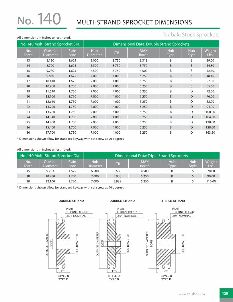
MULTI-STRAND SPROCKET DIMENSIONSNo. 140 Tsubaki Stock Sprockets
No. 140 Multi-Strand Sprocket Dia. Dimensional Data: Double Strand Sprockets
No. Teeth
Outside Diameter
Plain Bore
Hub Diameter LTB MAX
Bore * Hub Type
Hub Style
Weight Lbs.
13 8.150 1.625 5.000 3.750 3.313 B S 29.00
14 8.720 1.625 5.500 3.750 3.750 B S 34.80
15 9.280 1.625 6.500 3.750 4.500 B S 42.50
16 9.850 1.625 7.000 4.000 5.250 B S 48.10
17 10.410 1.625 7.000 4.000 5.250 B S 57.50
18 10.980 1.750 7.000 4.000 5.250 B S 65.60
19 11.540 1.750 7.000 4.000 5.250 B D 72.00
20 12.100 1.750 7.000 4.000 5.250 B D 76.00
21 12.660 1.750 7.000 4.000 5.250 B D 82.00
22 13.220 1.750 7.000 4.000 5.250 B D 94.00
23 13.780 1.750 7.000 4.000 5.250 B D 100.00
24 14.340 1.750 7.000 4.000 5.250 B D 104.00
25 14.900 1.750 7.000 4.000 5.250 B D 120.00
26 15.460 1.750 7.000 4.000 5.250 B D 128.00
30 17.700 1.750 7.000 4.000 5.250 B D 163.50
No. 140 Multi-Strand Sprocket Dia. Dimensional Data: Triple Strand SprocketsNo.
TeethOutside
DiameterPlain Bore
Hub Diameter LTB MAX
Bore * Hub Type
Hub Style
Weight Lbs.
15 9.283 1.625 6.500 5.688 4.500 B S 70.00
18 10.980 1.750 7.000 5.938 5.250 B S 90.00
20 12.100 1.750 7.000 5.938 5.250 B S 110.00
* Dimensions shown allow for standard keyway with set screw at 90 degrees
* Dimensions shown allow for standard keyway with set screw at 90 degrees
OU
TSID
EDI
AMET
ER
OU
TSID
EDI
AMET
ER
BORE
OU
TSID
EDI
AMET
ERBO
RE
BORE
HU
BDI
AMET
ER
HU
BDI
AMET
ER
HU
BDI
AMET
ER
OU
TSID
EDI
AMET
ERBO
RE
HU
BDI
AMET
ER
STYLE STYPE B
STYLE STYPE B
STYLE DTYPE B
DOUBLE STRAND DOUBLE STRAND TRIPLE STRAND TRIPLE STRAND
LTB
STYLE DTYPE B
LTB LTB LTB
TOOTH (NOMINAL)PLATE THICKNESS
TOOTH (NOMINAL)PLATE THICKNESS
PLATE T ICKNESS 2.818
PLATE T ICKNESS 2.818
PLATE T ICKNESS 4. 42
.894 NOMINAL .894 NOMINAL .894 NOMINAL
All dimensions in inches unless noted.
All dimensions in inches unless noted.
129www.tsubaki.ca
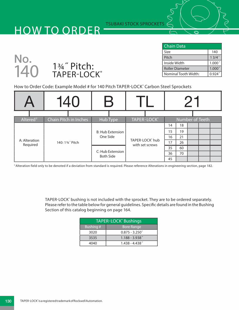
HOW TO ORDERTSUBAKI STOCK SPROCKETS
140
Chain DataSize 140Pitch 1 3/4˝Inside Width 1.000˝Roller Diameter 1.000˝Nominal Tooth Width: 0.924˝
No.1¾˝ Pitch: TAPER-LOCK®
How to Order Code: Example Model # for 140 Pitch TAPER-LOCK® Carbon Steel Sprockets
!! Alteration field only to be denoted if a deviation from standard is required. Please reference Alterations in engineering section, page 182.
A 140 B TL 21Altered !! Chain Pitch in Inches Hub Type TAPER-LOCK® Number of Teeth
A: Alteration Required 140: 1¾˝ Pitch
B: Hub Extension One Side
TAPER-LOCK® hub with set screws
14 18
15 1916 2117 26
C: Hub Extension Both Side
35 6036 7045
TAPER-LOCK® bushing is not included with the sprocket. They are to be ordered separately. Please refer to the table below for general guidelines. Speci�c details are found in the Bushing Section of this catalog beginning on page 164.
TAPER-LOCK® BushingsBushing # Bore Range
3020 0.875 - 3.250˝3535 1.188 - 3.938˝4040 1.438 - 4.438˝
TAPER-LOCK® is a registered trademark of Rockwell Automation.130

TAPER-LOCK® SPROCKET DIMENSIONSNo. 140 Tsubaki Stock Sprockets
No. 140 TAPER-LOCK® Sprockets Dimensional Data TAPER-LOCK® Sprockets
No. Teeth
Outside Diameter Bushing # Hub
Diameter LTB MAX Bore * Hub Type
Hub Style
Weight Lbs.
14 8.720 3020 5.250 2.000 3.250 B S 10.00
15 9.280 3020 5.250 2.000 3.250 B S 12.00
16 9.850 3020 5.250 2.000 3.250 B E 14.00
17 10.410 3020 5.250 2.000 3.250 B E 16.00
18 10.980 3020 5.250 2.000 3.250 B E 18.00
19 11.540 3020 5.250 2.000 3.250 B E 20.00
21 12.660 3020 5.250 2.000 3.250 B E 24.00
26 15.460 3020 5.250 2.000 3.250 B E 40.00
35 20.490 3535 6.500 3.500 3.938 C E 78.00
36 21.050 3535 6.500 3.500 3.938 C E 83.00
45 26.080 4040 7.750 4.000 4.438 C E 118.00
60 34.400 4040 7.750 4.000 4.438 C E 188.00
70 40.020 4040 7.750 4.000 4.438 C E 241.00
STYLE STYPE B
LTB
TOOTH (NOMINAL)
OU
TSID
EDI
AMET
ER
STYLE ETYPE C
OU
TSID
EDI
AMET
ER
OU
TSID
EDI
AMET
ER
HU
BDI
AMET
ER
HU
BDI
AMET
ER
HU
BDI
AMET
ER
STYLE ETYPE B
LTB LTB
TOOTH (NOMINAL) TOOTH (NOMINAL)
SINGLE “TAPER-LOCK” STYLE DOUBLE “TAPER-LOCK” STYLE
.924NOMINAL
.924NOMINAL
.924NOMINAL
* Please reference TAPER-LOCK® bushing dimension table on page 165 for specific information on MAX Bore and keyway data.
All dimensions in inches unless noted.
131www.tsubaki.ca

HOW TO ORDERTSUBAKI STOCK SPROCKETS
140
Chain DataSize 140Pitch 1 3/4˝Inside Width 1.000˝Roller Diameter 1.000˝Nominal Tooth Width: 0.924˝
No.1¾˝ Pitch: QD®
A 140 SF 13How to Order Code: Example Model # for 140 Pitch QD® Carbon Steel Sprockets
Altered !! Chain Pitch in Inches QD® Hub Type Number of Teeth
A: Alteration Required 140: 1¾˝ Pitch
SF: QD® Hub 11 - 13 tooth sprocket
11 13
12
E: QD® Hub 14 - 22 tooth sprocket
14 16 18 20 22
15 17 19 21
F: QD® Hub 23 - 36 tooth sprocket
23 25 30 36
24 26 35
J: QD® Hub 40 - 60 tooth sprocket
40 48 60
45 54
M: QD® Hub 70 & 80 tooth sprocket
70
80
!! Alteration field only to be denoted if a deviation from standard is required. Please reference Alterations in engineering section, page 182.
QD® bushing is not included with the sprocket. They are to be ordered separately. Please refer to the table below for general guidelines. Specific details are found in the Bushing Section of this catalog beginning on page 170.
QD® BushingsBushing # Bore Range
SF 0.500 - 2.938"E 0.875 - 3.500"F 1.000 - 4.000"J 1.500 - 4.500"
M 2.000 - 5.500"
QD® is a registered trademark of, and is used under license agreement from Emerson Electric Co.132

QD® SPROCKET DIMENSIONSNo. 140 Tsubaki Stock Sprockets
No. 140 QD® Sprockets Dimensional Data QD® Sprockets
No. Teeth
Outside Dia.
QD® Bushing #
MAX Bore *
Hub Dia. LTB X Y L F Hub
TypeHub Style
Weight Lbs.
11 7.010 SF 2.938 4.438 1.250 2.250 2.250 1.098 4.625 B S 5.60
12 7.580 SF 2.938 4.875 1.250 2.250 2.250 1.098 4.625 B S 7.40
13 8.150 SF 2.938 5.000 1.250 2.250 2.250 1.098 4.625 B S 8.90
14 8.720 E 3.500 6.125 1.625 2.938 2.625 1.563 6.000 B1 S 11.60
15 9.280 E 3.500 6.125 1.625 2.938 2.625 1.563 6.000 B1 S 14.20
16 9.850 E 3.500 6.250 1.625 2.938 2.625 1.563 6.000 B1 E 15.90
17 10.410 E 3.500 6.250 1.625 2.938 2.625 1.563 6.000 B1 E 18.00
18 10.980 E 3.500 6.250 1.625 2.938 2.625 1.563 6.000 B1 E 19.60
19 11.540 E 3.500 6.250 1.625 2.938 2.625 1.563 6.000 B1 E 22.00
20 12.100 E 3.500 6.250 1.625 2.938 2.625 1.563 6.000 B1 E 24.60
21 12.660 E 3.500 6.250 1.625 2.938 2.625 1.563 6.000 B1 E 27.60
22 13.220 E 3.500 6.250 1.625 2.938 2.625 1.563 6.000 B1 E 29.50
23 13.780 F 4.000 7.000 2.500 4.000 3.625 2.563 6.625 B1 E 36.40
24 14.340 F 4.000 7.000 2.500 4.000 3.625 2.563 6.625 B1 E 40.10
25 14.900 F 4.000 7.000 2.500 4.000 3.625 2.563 6.625 B1 E 42.30
26 15.460 F 4.000 7.000 2.500 4.000 3.625 2.563 6.625 B1 E 46.50
30 17.700 F 4.000 7.000 2.500 4.000 3.625 2.563 6.625 B1 E 60.40
35 20.490 F 4.000 7.000 2.500 4.000 3.625 1.000 6.625 C E 78.00
36 21.050 F 4.000 7.000 2.500 4.000 3.625 1.000 6.625 C E 84.00
40 23.290 J 4.500 8.000 3.188 5.000 4.500 1.188 7.250 C E 98.00
45 26.080 J 4.500 8.000 3.188 5.000 4.500 1.188 7.250 C E 120.00
48 27.750 J 4.500 8.000 3.188 5.000 4.500 1.188 7.250 C E 129.00
54 31.100 J 4.500 8.000 3.188 5.000 4.500 1.188 7.250 C E 149.00
60 34.440 J 4.500 8.000 3.188 5.000 4.500 1.188 7.250 C E 185.00
70 40.020 M 5.500 10.000 5.188 6.750 6.750 2.906 9.000 C1 E 264.00
80 45.590 M 5.500 10.000 5.188 6.750 6.750 2.906 9.000 C1 E 348.00
STYLE STYPE B
X
L
YLTB
OU
TSID
EDI
AMET
ER
HU
BDI
AMET
ER
Y Y Y
HU
BDI
AMET
ER
OU
TSID
EDI
AMET
ER
HU
BDI
AMET
ER
HU
BDI
AMET
ER
OU
TSID
EDI
AMET
ER
OU
TSID
EDI
AMET
ER
F F F F
STYLE ETYPE B1
STYLE ETYPE C
STYLE ETYPE C1
X XX
LL
L
LTB LTB LTBTOOTH(NOMINAL)
TOOTH(NOMINAL) TOOTH
(NOMINAL)TOOTH
(NOMINAL).924NOMINAL.924
NOMINAL.924NOMINAL
.924NOMINAL
* Please reference QD® bushing dimension table on page 171 for specific information on MAX Bore and keyway data.
All dimensions in inches unless noted.
133www.tsubaki.ca

HOW TO ORDERTSUBAKI STOCK SPROCKETS
160
Chain DataSize 160Pitch 2˝Inside Width 1.250 ˝Roller Diameter 1.125˝Nominal Tooth Width: 1.156˝
No.2˝ Pitch: PLAIN BORE
A 160 A 25Altered !! Chain Pitch in Inches Hub Type Number of Teeth
A: Alteration Required
160: 2˝ Pitch
A: No Hub Extension
8 14 20 26 409 15 21 27 45
10 16 22 28 4811 17 23 30 5412 18 24 35 6013 19 25 36
B: Hub Extension One Side
8 14 20 269 15 21 27
10 16 22 2811 17 23 3012 18 2413 19 25
C: Hub Extension Both Sides
35 45 6036 4840 54
How to Order Code: Example Model # for 160 Pitch Plain Bore Carbon Steel Sprockets
!! Alteration field only to be denoted if a deviation from standard is required. Please reference Alterations in engineering section, page 182.
TOOTH (NOMINAL) TOOTH (NOMINAL)TOOTH (NOMINAL)TOOTH (NOMINAL)
TYPE A STYLE DTYPE B
STYLE STYPE B
STYLE DTYPE C
OU
TSID
E DI
AMET
ER
OU
TSID
E DI
AMET
ERBO
RE
HU
B DI
AMET
ER
LTB
BORE
HU
B DI
AMET
ER
LTBLTB
OU
TSID
E DI
AMET
ERBO
RE
BORE
OU
TSID
E DI
AMET
ER
HU
B DI
AMET
ER
1.156 NOMINAL 1.156 NOMINAL 1.156 NOMINAL 1.156 NOMINAL
134

PLAIN BORE SPROCKET DIMENSIONSNo. 160 Tsubaki Stock Sprockets
No. 160 Plain Bore Sprocket Dia. Type “A” Plain Bore Type “B” & “C” Plain Bore
No. Teeth
Outside Dia.
Pitch Dia.
Caliper Dia.
Plain Bore
Wt. Lbs.
Plain Bore
MAX Bore *
Hub Dia. LTB Hub
TypeHub Style
Wt. Lbs.
8 6.030 5.226 4.101 1.500 5.00 1.500 1.875 3.250 2.250 B S 8.00
9 6.700 5.848 4.635 1.500 7.00 1.500 2.125 3.625 2.250 B S 10.00
10 7.380 6.472 5.347 1.500 8.00 1.500 2.750 4.125 2.250 B S 12.00
11 8.010 7.100 5.902 1.500 10.00 1.500 3.250 4.750 2.500 B S 17.00
12 8.660 7.728 6.603 1.500 12.00 1.500 3.750 5.500 2.500 B S 21.00
13 9.310 8.358 7.171 1.500 16.00 1.500 4.000 6.000 2.750 B S 28.00
14 9.960 8.988 7.863 1.500 17.00 1.500 4.500 6.500 2.750 B D 32.00
15 10.610 9.620 8.442 1.500 21.00 1.500 5.250 7.000 2.750 B D 37.00
16 11.260 10.252 9.127 1.500 24.00 1.500 5.250 7.000 2.750 B D 41.00
17 11.900 10.844 9.713 1.500 27.00 1.500 5.250 7.000 2.750 B D 45.00
18 12.540 11.518 10.393 1.500 30.00 1.500 5.250 7.000 2.750 B D 48.00
19 13.190 12.152 10.985 1.500 34.00 1.500 5.250 7.000 2.750 B D 52.00
20 13.830 12.784 11.659 1.500 38.00 1.500 5.250 7.000 2.750 B D 56.00
21 14.470 13.420 12.256 1.500 42.00 1.500 5.250 7.000 2.750 B D 59.00
22 15.110 14.054 12.929 1.500 46.00 1.500 5.250 7.000 2.750 B D 65.00
23 15.750 14.688 13.529 1.500 50.00 1.500 5.250 7.000 2.750 B D 68.00
24 16.390 15.322 14.197 1.500 56.00 1.500 5.250 7.000 3.000 B D 77.00
25 17.030 15.958 14.801 1.500 61.00 1.500 5.250 7.000 3.000 B D 81.00
26 17.670 16.592 15.467 1.500 65.00 1.500 5.250 7.000 3.000 B D 86.00
27 18.310 17.228 16.073 1.500 71.00 1.500 5.250 7.000 3.000 B D 91.00
28 18.950 17.862 16.737 1.500 77.00 1.500 5.250 7.000 3.000 B D 98.00
30 20.230 19.134 18.009 1.500 90.00 1.500 5.250 7.000 3.000 B D 108.00
35 23.420 22.312 21.164 1.500 121.00 1.500 5.500 8.000 4.500 C D 154.00
36 24.060 22.948 21.823 1.500 134.00 1.500 5.500 8.000 4.500 C D 170.00
40 26.610 25.492 24.367 1.500 138.00 1.500 5.500 8.000 4.500 C D 196.00
45 29.800 28.672 27.529 1.500 204.00 1.500 5.500 8.000 5.000 C D 234.00
48 31.714 30.580 29.455 1.500 233.00 1.500 5.500 8.000 5.000 C D 250.00
54 35.540 34.396 33.271 1.500 294.00 1.500 5.500 8.000 5.000 C D 345.00
60 39.360 38.214 37.089 1.500 360.00 1.500 5.500 8.000 5.000 C D 415.00
* Dimensions shown allow for standard keyway with set screw at 90 degrees
All dimensions in inches unless noted.
135www.tsubaki.ca

HOW TO ORDERTSUBAKI STOCK SPROCKETS
160
Chain DataSize 160Pitch 2˝Inside Width 1.250 ˝Roller Diameter 1.125˝Nominal Tooth Width: 1.119˝
No.2˝ Pitch: MULTI-STRAND
How to Order Code: Example Model # for 160 Pitch Multi-Strand Carbon Steel Sprockets
A D 160 B 21Altered !! Multi Chain Pitch in Inches Hub Type Number of Teeth
A: Alteration Required
D: Double Strand
160: 2˝ PitchB: Hub Extension One Side
13 17 21 25
14 18 22 26
15 19 23 30
16 20 24!! Alteration field only to be denoted if a deviation from standard is required. Please reference Alterations in engineering section, page 182.
136

MULTI-STRAND SPROCKET DIMENSIONSNo. 160 Tsubaki Stock Sprockets
No. 160 Multi-Strand Sprocket Dia. Dimensional Data: Double Strand Sprockets
No. Teeth
Outside Diameter
Plain Bore
Hub Diameter LTB MAX
Bore * Hub Type
Hub Style
Weight Lbs.
13 9.310 2.000 6.000 4.750 4.000 B D 48.00
14 9.960 2.000 6.750 4.750 4.750 B D 58.00
15 10.610 2.000 7.000 4.750 5.250 B D 68.00
16 11.260 2.000 7.000 4.750 5.250 B D 75.00
17 11.900 2.000 7.000 4.750 5.250 B D 91.00
18 12.540 2.000 7.000 4.750 5.250 B D 96.00
19 13.190 2.000 7.000 4.750 5.250 B D 107.00
20 13.830 2.000 7.000 4.750 5.250 B D 119.00
21 14.470 2.000 7.500 4.750 5.375 B D 130.00
22 15.110 2.000 7.500 4.750 5.375 B D 141.00
23 15.750 2.000 7.500 4.750 5.375 B D 157.00
24 16.390 2.000 7.500 4.750 5.375 B D 171.00
25 17.030 2.000 7.500 4.750 5.375 B D 187.00
26 17.670 2.000 7.500 4.750 5.375 B D 201.00
30 20.230 2.000 7.500 4.750 5.375 B D 260.00
* Dimensions shown allow for standard keyway with set screw at 90 degrees
OU
TSID
EDI
AMET
ER
OU
TSID
EDI
AMET
ER
BORE
OU
TSID
EDI
AMET
ERBO
RE
BORE
HU
BDI
AMET
ER
HU
BDI
AMET
ER
HU
BDI
AMET
ER
OU
TSID
EDI
AMET
ERBO
RE
HU
BDI
AMET
ERSTYLE STYPE B
STYLE STYPE B
STYLE DTYPE B
DOUBLE STRAND DOUBLE STRAND TRIPLE STRAND TRIPLE STRAND
LTB
STYLE DTYPE B
LTB LTB LTB
TOOTH (NOMINAL)PLATE THICKNESS
TOOTH (NOMINAL)PLATE THICKNESSPLATE T ICKNESS .4241.119 NOMINAL
All dimensions in inches unless noted.
137www.tsubaki.ca

HOW TO ORDERTSUBAKI STOCK SPROCKETS
160
Chain DataSize 160Pitch 2˝Inside Width 1.250 ˝Roller Diameter 1.125˝Nominal Tooth Width: 1.156˝
No.2˝ Pitch: QD®
A 160 F 17How to Order Code: Example Model # for 160 Pitch QD® Carbon Steel Sprockets
Altered !! Chain Pitch in Inches QD® Hub Type Number of Teeth
A: Alteration Required 160: 2˝ Pitch
E: QD® Hub 13 - 14 tooth sprocket
13
14
F: QD® Hub 15 - 25 tooth sprocket
15 18 21 24
16 19 22 25
17 20 23
J: QD® Hub 26 - 35 tooth sprocket
26 35
28
30
M: QD® Hub 40 - 60 tooth sprocket
40 60
45
54
!! Alteration field only to be denoted if a deviation from standard is required. Please reference Alterations in engineering section, page 182.
QD® bushing is not included with the sprocket. They are to be ordered separately. Please refer to the table below for general guidelines. Specific details are found in the Bushing Section of this catalog beginning on page 170.
QD® BushingsBushing # Bore Range
E 0.875 - 3.500"F 1.000 - 4.000"J 1.500 - 4.500"
M 2.000 - 5.500"
QD® is a registered trademark of, and is used under license agreement from Emerson Electric Co.138

QD® SPROCKET DIMENSIONSNo. 160 Tsubaki Stock Sprockets
No. 160 QD® Sprockets Dimensional Data QD® Sprockets
No. Teeth
Outside Dia.
QD® Bushing #
MAX Bore *
Hub Dia. LTB X Y L F Hub
TypeHub Style
Weight Lbs.
13 9.310 E 3.500 6.000 1.625 2.625 2.937 1.313 6.000 B1 S 14.00
14 9.960 E 3.500 6.000 1.625 2.625 2.937 1.313 6.000 B1 S 15.00
15 10.610 F 4.000 6.625 2.500 3.625 4.000 2.313 6.625 B1 E 24.00
16 11.260 F 4.000 6.625 2.500 3.625 4.000 2.313 6.625 B1 E 27.00
17 11.900 F 4.000 6.625 2.500 3.625 4.000 2.313 6.625 B1 E 31.00
18 12.540 F 4.000 6.625 2.500 3.625 4.000 2.313 6.625 B1 E 35.00
19 13.190 F 4.000 6.625 2.500 3.625 4.000 2.313 6.625 B1 E 38.00
20 13.830 F 4.000 6.625 2.500 3.625 4.000 2.313 6.625 B1 E 42.00
21 14.740 F 4.000 6.625 2.500 3.625 4.000 2.313 6.625 B1 E 45.00
22 15.110 F 4.000 6.625 2.500 3.625 4.000 2.313 6.625 B1 E 51.00
23 15.750 F 4.000 6.625 2.500 3.625 4.000 2.313 6.625 B1 E 55.00
24 16.390 F 4.000 6.625 2.500 3.625 4.000 2.313 6.625 B1 E 59.00
25 17.030 F 4.000 6.625 2.500 3.625 4.000 2.313 6.625 B1 E 64.00
26 17.670 J 4.500 7.250 3.188 4.500 5.000 1.188 7.250 C E 74.00
28 18.950 J 4.500 7.250 3.188 4.500 5.000 1.188 7.250 C E 84.00
30 20.230 J 4.500 7.250 3.188 4.500 5.000 1.188 7.250 C E 96.00
35 23.420 J 4.500 7.250 3.188 4.500 5.000 1.188 7.250 C E 116.00
40 26.610 M 5.500 9.000 5.188 6.750 6.750 1.594 9.000 C1 E 174.00
45 29.800 M 5.500 9.000 5.188 6.750 6.750 1.594 9.000 C1 E 208.00
54 35.540 M 5.500 9.000 5.188 6.750 6.750 1.594 9.000 C1 E 262.00
60 39.360 M 5.500 9.000 5.188 6.750 6.750 1.594 9.000 C1 E 310.00
STYLE STYPE B1
X
L
YLTB
OU
TSID
EDI
AMET
ER
HU
BDI
AMET
ER
Y Y Y
HU
BDI
AMET
ER
OU
TSID
EDI
AMET
ER
HU
BDI
AMET
ER
HU
BDI
AMET
ER
OU
TSID
EDI
AMET
ER
OU
TSID
EDI
AMET
ER
F F F F
STYLE ETYPE B1
STYLE ETYPE C
STYLE ETYPE C1
X XX
LL
L
LTB LTB LTBTOOTH(NOMINAL)
TOOTH(NOMINAL) TOOTH
(NOMINAL)TOOTH
(NOMINAL)1.156NOMINAL1.156
NOMINAL1.156NOMINAL
1.156NOMINAL
* Please reference QD® bushing dimension table on page 171 for specific information on MAX Bore and keyway data.
All dimensions in inches unless noted.
139www.tsubaki.ca

HOW TO ORDERTSUBAKI STOCK SPROCKETS
180
Chain DataSize 180Pitch 2 ¼˝Inside Width 1.406˝Roller Diameter 1.406˝Nominal Tooth Width: 1.301˝
No.2 ¼˝ Pitch: PLAIN BORE
A 180 B 25Altered !! Chain Pitch in Inches Hub Type Number of Teeth
A: Alteration Required
180: 2 ¼˝ Pitch
A: No Hub Extension
11 15 19 2312 16 20 2413 17 21 2514 18 22 28
B: Hub Extension One Side
11 15 19 2312 16 20 2413 17 21 2514 18 22 28
How to Order Code: Example Model # for 180 Pitch Plain Bore Carbon Steel Sprockets
!! Alteration field only to be denoted if a deviation from standard is required. Please reference Alterations in engineering section, page 182.
140

PLAIN BORE SPROCKET DIMENSIONSNo. 180 Tsubaki Stock Sprockets
No. 180 Plain Bore Sprocket Dia. Type “A” Plain Bore Type “B” Plain Bore
No. Teeth
Outside Dia.
Pitch Dia.
Caliper Dia.
Plain Bore
Wt. Lbs.
Plain Bore
MAX Bore *
Hub Dia. LTB Hub
TypeHub Style
Wt. Lbs.
11 9.010 7.986 6.499 1.500 14.00 1.500 3.625 5.500 3.000 B S 29.00
12 9.750 8.693 7.287 1.500 16.00 1.500 4.000 6.000 3.000 B D 32.00
13 10.480 9.402 7.927 1.500 20.00 1.500 4.625 6.750 3.125 B D 40.00
14 11.210 10.111 8.705 1.500 24.00 1.500 5.250 7.000 3.125 B D 44.00
15 11.930 10.822 9.357 1.500 28.00 1.500 5.250 7.000 3.125 B D 48.00
16 12.660 11.533 10.127 1.500 32.00 1.500 5.250 7.000 3.125 B D 52.00
17 13.390 12.245 10.787 1.500 37.00 1.500 5.250 7.000 3.125 B D 58.00
18 14.110 12.957 11.551 1.500 43.00 1.500 5.250 7.000 3.125 B D 63.00
19 14.830 13.670 12.217 1.500 47.00 1.500 5.375 7.500 3.375 B D 74.00
20 15.560 14.383 12.977 1.500 53.00 1.500 5.375 7.500 3.375 B D 81.00
21 16.280 15.096 13.648 1.500 57.00 1.500 5.375 7.500 3.375 B D 83.00
22 17.000 15.810 14.404 1.500 62.00 1.500 5.375 7.500 3.375 B D 92.00
23 17.720 16.524 15.079 1.500 69.00 1.500 5.375 7.500 3.375 B D 99.00
24 18.440 17.238 15.832 1.500 77.00 1.500 5.375 7.500 3.375 B D 105.00
25 19.160 17.952 16.511 1.500 84.00 1.500 5.375 7.500 3.375 B D 113.00
28 21.320 20.096 18.690 1.500 104.00 1.500 5.500 8.000 3.500 B D 135.00
TOOTH (NOMINAL) TOOTH (NOMINAL)TOOTH (NOMINAL)TOOTH (NOMINAL)
TYPE A STYLE DTYPE B
STYLE STYPE B
STYLE DTYPE C
OU
TSID
E DI
AMET
ER
OU
TSID
E DI
AMET
ERBO
RE
HU
B DI
AMET
ER
LTB
BORE
HU
B DI
AMET
ER
LTBLTB
OU
TSID
E DI
AMET
ERBO
RE
BORE
OU
TSID
E DI
AMET
ER
HU
B DI
AMET
ER
1.301 NOMINAL 1.301 NOMINAL 1.301 NOMINAL
* Dimensions shown allow for standard keyway with set screw at 90 degrees
All dimensions in inches unless noted.
141www.tsubaki.ca

HOW TO ORDERTSUBAKI STOCK SPROCKETS
200
Chain DataSize 200Pitch 2 ½˝Inside Width 1.500˝Roller Diameter 1.562˝Nominal Tooth Width: 1.389˝
No.2 ½˝ Pitch: PLAIN BORE
A 200 B 25How to Order Code: Example Model # for 200 Pitch Plain Bore Carbon Steel Sprockets
!! Alteration field only to be denoted if a deviation from standard is required. Please reference Alterations in engineering section, page 182.
Altered !! Chain Pitch in Inches Hub Type Number of Teeth
A: Alteration Required
200: 2 ½˝ Pitch
A: No Hub Extension
10 14 18 25 4511 15 19 30 5412 16 20 35 6013 17 21 40
B: Hub Extension One Side
10 14 18 2511 15 19
12 16 2013 17 21
C: Hub Extension Both Sides
30 4535 5440 60
142

PLAIN BORE SPROCKET DIMENSIONSNo. 200 Tsubaki Stock Sprockets
No. 200 Plain Bore Sprocket Dia. Type “A” Plain Bore Type “B” & “C” Plain Bore
No. Teeth
Outside Dia.
Pitch Dia.
Caliper Dia.
Plain Bore
Wt. Lbs.
Plain Bore
MAX Bore *
Hub Dia. LTB Hub
TypeHub Style
Wt. Lbs.
10 9.200 8.090 6.528 1.500 16.00 1.500 3.750 5.500 3.000 B S 26.00
11 10.020 8.872 7.219 1.500 20.00 1.500 4.000 6.000 3.000 B D 33.00
12 10.830 9.660 8.098 1.500 24.00 1.500 4.500 6.500 3.000 B D 37.00
13 11.640 10.447 8.808 1.500 30.00 1.500 5.250 7.000 3.000 B D 46.00
14 12.460 11.235 9.673 1.500 32.00 1.500 5.375 7.500 3.500 B D 59.00
15 13.260 12.025 10.397 1.500 40.00 1.500 5.375 7.500 3.500 B D 64.00
16 14.070 12.815 11.253 1.500 46.00 1.500 5.375 7.500 3.500 B D 72.00
17 14.870 13.605 11.985 1.500 51.00 1.500 5.375 7.500 3.500 B D 76.00
18 15.680 14.397 12.835 1.500 57.00 1.500 5.375 7.500 3.500 B D 84.00
19 16.480 15.190 13.576 1.500 65.00 1.500 5.375 7.500 3.500 B D 91.00
20 17.290 15.982 14.420 1.500 72.00 1.500 5.375 7.500 3.500 B D 98.00
21 18.090 16.775 15.166 1.500 82.00 1.500 5.375 7.500 3.500 B D 106.00
25 20.490 19.152 17.590 1.500 113.00 1.500 5.750 8.500 4.000 B D 153.00
30 25.290 23.917 22.355 1.500 167.00 1.500 5.750 8.500 4.500 C D 212.00
35 29.280 27.890 26.300 1.500 227.00 1.500 5.750 8.500 4.500 C D 254.00
40 33.270 31.865 30.303 1.500 301.00 1.500 6.000 9.000 5.000 C D 320.00
45 37.250 35.840 34.256 1.500 356.00 1.500 6.000 9.000 5.000 C D 390.00
54 44.420 42.995 41.433 1.500 479.00 1.500 6.500 9.500 5.500 C D 555.00
60 49.200 47.767 46.205 1.500 654.00 1.500 6.500 9.500 5.500 C D 692.00
TOOTH (NOMINAL) TOOTH (NOMINAL)TOOTH (NOMINAL)TOOTH (NOMINAL)
TYPE A STYLE DTYPE B
STYLE STYPE B
STYLE DTYPE C
OU
TSID
E DI
AMET
ER
OU
TSID
E DI
AMET
ERBO
RE
HU
B DI
AMET
ER
LTB
BORE
HU
B DI
AMET
ER
LTBLTB
OU
TSID
E DI
AMET
ERBO
RE
BORE
OU
TSID
E DI
AMET
ER
HU
B DI
AMET
ER
1.389 NOMINAL 1.389 NOMINAL 1.389 NOMINAL 1.389 NOMINAL
* Dimensions shown allow for standard keyway with set screw at 90 degrees
All dimensions in inches unless noted.
143www.tsubaki.ca

HOW TO ORDERTSUBAKI STOCK SPROCKETS
240
Chain DataSize 240Pitch 3˝Inside Width 1.875˝Roller Diameter 1.875˝Nominal Tooth Width: 1.738˝
No.3˝ Pitch: PLAIN BORE
A 240 B 21Altered !! Chain Pitch in Inches Hub Type Number of Teeth
A: Alteration Required
240: 3˝ Pitch
A: No Hub Extension
10 14 18 25 4511 15 19 30 5412 16 20 35 6013 17 21 40
B: Hub Extension One Side
10 14 18 2511 15 1912 16 2013 17 21
C: Hub Extension Both Sides
30 4535 5440 60
How to Order Code: Example Model # for 240 Pitch Plain Bore Carbon Steel Sprockets
!! Alteration field only to be denoted if a deviation from standard is required. Please reference Alterations in engineering section, page 182.
144

PLAIN BORE SPROCKET DIMENSIONSNo. 240 Tsubaki Stock Sprockets
No. 240 Plain Bore Sprocket Dia. Type “A” Plain Bore Type “B” & “C” Plain Bore
No. Teeth
Outside Dia.
Pitch Dia.
Caliper Dia.
Plain Bore
Wt. Lbs.
Plain Bore
MAX Bore *
Hub Dia. LTB Hub
TypeHub Style
Wt. Lbs.
10 11.030 9.708 7.833 1.500 30.00 1.500 4.500 6.500 3.375 B S 49.00
11 12.020 10.648 8.665 1.500 37.00 1.500 4.750 7.000 3.875 B D 66.00
12 13.000 11.591 9.716 1.500 45.00 1.500 5.375 7.500 3.875 B D 72.00
13 13.970 12.536 10.569 1.500 54.00 1.500 5.375 7.500 3.875 B D 81.00
14 14.940 13.482 11.607 1.500 62.00 1.500 5.375 7.500 3.875 B D 88.00
15 15.910 14.429 12.475 1.500 68.00 1.500 5.375 7.500 3.875 B D 98.00
16 16.880 15.377 13.502 1.500 82.00 1.500 5.500 8.000 4.125 B D 120.00
17 17.850 16.327 14.382 1.500 93.00 1.500 5.500 8.000 4.125 B D 137.00
18 18.810 17.276 15.401 1.500 108.00 1.500 5.500 8.000 4.125 B D 142.00
19 19.780 18.227 16.289 1.500 120.00 1.500 5.500 8.000 4.125 B D 154.00
20 20.740 19.177 17.302 1.500 128.00 1.500 5.500 8.000 4.125 B D 169.00
21 21.710 20.129 18.197 1.500 148.00 1.500 5.500 8.000 4.125 B D 186.00
25 25.550 23.936 22.014 1.500 208.00 1.500 5.500 8.000 4.125 B D 254.00
30 30.340 28.700 26.825 1.500 310.00 1.500 6.000 9.000 6.250 C D 398.00
35 35.130 33.467 31.559 1.500 416.00 1.500 6.000 9.000 6.250 C D 527.00
40 39.920 38.237 36.362 1.500 548.00 1.500 7.000 10.000 6.750 C D 672.00
45 44.700 43.007 41.106 1.500 702.00 1.500 7.000 10.000 6.750 C D 850.00
54 53.310 51.595 49.720 1.500 1022.00 1.500 7.000 10.000 6.750 C D 1148.00
60 59.040 57.322 55.447 1.500 1268.00 1.500 7.000 10.000 6.750 C D 1419.00
TOOTH (NOMINAL) TOOTH (NOMINAL)TOOTH (NOMINAL)TOOTH (NOMINAL)
TYPE A STYLE DTYPE B
STYLE STYPE B
STYLE DTYPE C
OU
TSID
E DI
AMET
ER
OU
TSID
E DI
AMET
ERBO
RE
HU
B DI
AMET
ER
LTB
BORE
HU
B DI
AMET
ER
LTBLTB
OU
TSID
E DI
AMET
ERBO
RE
BORE
OU
TSID
E DI
AMET
ER
HU
B DI
AMET
ER
1.738 NOMINAL TOOTH (NOMINAL) TOOTH (NOMINAL)TOOTH (NOMINAL)TOOTH (NOMINAL)
TYPE A STYLE DTYPE B
STYLE STYPE B
STYLE DTYPE C
OU
TSID
E DI
AMET
ER
OU
TSID
E DI
AMET
ERBO
RE
HU
B DI
AMET
ER
LTB
BORE
HU
B DI
AMET
ER
LTBLTB
OU
TSID
E DI
AMET
ERBO
RE
BORE
OU
TSID
E DI
AMET
ER
HU
B DI
AMET
ER
1.738 NOMINAL 1.738 NOMINAL
* Dimensions shown allow for standard keyway with set screw at 90 degrees
All dimensions in inches unless noted.
145www.tsubaki.ca

Chain DataSize 2040Pitch 1˝Inside Width 5/16˝Roller Diameter 0.313˝Nominal Tooth Width: 0.284˝
A 2040 B 21Altered !! Chain Pitch in Inches Hub Type Number of Teeth
A: Alteration Required
2040: 1˝ Pitch
A: No Hub Extension
23 25 2824 26 30
B: Hub Extension One Side
11 17 2312 18 2413 19 2514 20 2615 21 2816 22 30
How to Order Code: Example Model # for 2040 Pitch Plain Bore Carbon Steel SprocketsConveyor or Drive Series standard roller Double Pitch sprocketsFor use with Tsubaki C2040/A2040 Chain - 1" Pitch
No.1˝ Pitch: DOUBLE PITCH2040
HOW TO ORDERTSUBAKI STOCK SPROCKETS
!! Alteration field only to be denoted if a deviation from standard is required. Please reference Alterations in engineering section, page 182.
146

PLAIN BORE SPROCKET DIMENSIONSNo. 2040 Tsubaki Stock Sprockets
No. 2040 Plain Bore Sprocket Dia. Type “A” Plain Bore Type “B” Plain Bore
No. Teeth
Outside Dia.
Pitch Dia.
Caliper Dia.
Plain Bore
Wt. Lbs.
Plain Bore
MAX Bore *
Hub Dia. LTB Hub
TypeHub Style
Wt. Lbs.
11 2.000 1.852 1.537 N/A N/A 0.500 0.813 1.375 ¨ 0.875 B S 0.34
12 2.170 2.000 1.688 N/A N/A 0.500 0.813 1.563 ¨ 0.875 B S 0.44
13 2.330 2.152 1.824 N/A N/A 0.500 0.656 1.563 ¨ 0.875 B S 0.48
14 2.490 2.305 1.993 N/A N/A 0.500 1.031 1.688 ¨ 0.875 B S 0.60
15 2.650 2.458 2.133 N/A N/A 0.625 1.219 1.781 0.875 B S 0.66
16 2.810 2.613 2.301 N/A N/A 0.625 1.281 1.875 0.875 B S 0.76
17 2.980 2.768 2.444 N/A N/A 0.625 1.313 2.047 1.000 B S 1.00
18 3.140 2.924 2.612 N/A N/A 0.625 1.469 2.219 1.000 B S 1.16
19 3.300 3.080 2.757 N/A N/A 0.625 1.625 2.375 1.000 B S 1.36
20 3.460 3.236 2.924 N/A N/A 0.625 1.750 2.547 1.000 B S 1.54
21 3.620 3.392 3.070 N/A N/A 0.625 1.781 2.703 1.000 B S 1.74
22 3.780 3.549 3.237 N/A N/A 0.625 1.875 2.875 1.000 B S 1.92
23 3.940 3.706 3.386 0.625 0.77 0.625 2.000 3.000 1.000 B D 2.16
24 4.100 3.864 3.552 0.625 0.84 0.625 2.250 3.250 1.000 B D 2.44
25 4.260 4.021 3.701 0.625 0.91 0.625 2.250 3.250 1.000 B D 2.48
26 4.420 4.179 3.867 0.625 1.00 0.625 2.250 3.250 1.000 B D 2.60
28 4.740 4.494 4.182 0.625 1.10 0.625 2.250 3.250 1.000 B D 2.74
30 5.060 4.810 4.498 0.625 1.30 0.625 2.250 3.250 1.000 B D 2.92
* Dimensions shown allow for standard keyway with set screw at 90 degrees¨ Has recessed groove in hub for chain clearanceN/A = Non applicable/Not Available as standard
TOOTH (NOMINAL) TOOTH (NOMINAL)TOOTH (NOMINAL)TOOTH (NOMINAL)
TYPE A STYLE DTYPE B
STYLE STYPE B
STYLE DTYPE C
OU
TSID
E DI
AMET
ER
OU
TSID
E DI
AMET
ERBO
RE
HU
B DI
AMET
ER
LTB
BORE
HU
B DI
AMET
ER
LTBLTB
OU
TSID
E DI
AMET
ERBO
RE
BORE
OU
TSID
E DI
AMET
ER
HU
B DI
AMET
ER
.284 NOMINAL .284 NOMINAL .284 NOMINAL
All dimensions in inches unless noted.
147www.tsubaki.ca

Chain DataSize 2042Pitch 1˝Inside Width 5/16˝Roller Diameter 0.625˝Nominal Tooth Width: 0.284˝
A 2042 B 26
How to Order Code: Example Model # for 2042 Pitch Plain Bore Carbon Steel SprocketsConveyor Series large roller Double Pitch sprocketsFor use with Tsubaki C2042 Chain - 1" Pitch
No.1˝ Pitch: DOUBLE PITCH2042
HOW TO ORDERTSUBAKI STOCK SPROCKETS
!! Alteration field only to be denoted if a deviation from standard is required. Please reference Alterations in engineering section, page 182.
Altered !! Chain Pitch in Inches Hub Type Number of Teeth
A: Alteration Required
2042: 1˝ Pitch
A: No Hub Extension
16 21 2617 22 2818 23 3019 2420 25
B: Hub Extension One Side
8 14 20 269 15 21 28
10 16 22 3011 17 2312 18 2413 19 25
148

PLAIN BORE SPROCKET DIMENSIONSNo. 2042 Tsubaki Stock Sprockets
No. 2042 Plain Bore Sprocket Dia. Type “A” Plain Bore Type “B” Plain Bore
No. Teeth
Outside Dia.
Pitch Dia.
Caliper Dia.
Plain Bore
Wt. Lbs.
Plain Bore
MAX Bore *
Hub Dia. LTB Hub
TypeHub Style
Wt. Lbs.
8 3.010 2.613 1.988 N/A N/A 0.625 1.281 1.875 0.875 B S 0.72
9 3.350 2.924 2.255 N/A N/A 0.625 1.469 2.219 0.875 B S 1.02
10 3.680 3.236 2.611 N/A N/A 0.625 1.750 2.547 1.000 B S 1.50
11 4.000 3.549 2.888 N/A N/A 0.625 1.875 2.625 1.000 B S 1.68
12 4.330 3.864 3.239 N/A N/A 0.625 2.250 3.063 1.000 B S 2.22
13 4.660 4.179 3.523 N/A N/A 0.625 2.250 3.250 1.000 B S 2.56
14 4.980 4.494 3.869 N/A N/A 0.625 2.250 3.250 1.000 B S 2.72
15 5.300 4.810 4.158 N/A N/A 0.625 2.250 3.250 1.000 B S 2.90
16 5.630 5.126 4.501 0.594 1.38 0.625 2.250 3.250 1.000 B D 3.10
17 5.950 5.442 4.794 0.594 1.66 0.625 2.250 3.250 1.000 B D 3.40
18 6.270 5.759 5.134 0.594 1.88 0.625 2.250 3.250 1.000 B D 3.56
19 6.590 6.076 5.430 0.594 2.06 0.625 2.250 3.250 1.000 B D 3.72
20 6.910 6.392 5.768 0.719 2.40 0.750 2.375 3.500 1.125 B D 4.72
21 7.240 6.710 6.066 0.719 2.62 0.750 2.375 3.500 1.125 B D 4.84
22 7.560 7.027 6.402 0.719 2.88 0.750 2.375 3.500 1.125 B D 5.04
23 7.880 7.344 6.702 0.719 3.14 0.750 2.375 3.500 1.125 B D 5.18
24 8.200 7.661 7.036 0.719 3.22 0.750 2.375 3.500 1.125 B D 5.58
25 8.520 7.979 7.338 0.719 3.50 0.750 2.375 3.500 1.125 B D 5.96
26 8.840 8.296 7.671 0.719 3.74 0.750 2.375 3.500 1.125 B D 6.22
28 9.480 8.931 8.307 0.719 4.76 0.750 2.375 3.500 1.125 B D 6.78
30 10.110 9.567 8.942 0.719 5.08 0.750 2.375 3.500 1.125 B D 7.56
* Dimensions shown allow for standard keyway with set screw at 90 degreesN/A = Non applicable/Not Available as standard
TOOTH (NOMINAL) TOOTH (NOMINAL)TOOTH (NOMINAL)TOOTH (NOMINAL)
TYPE A STYLE DTYPE B
STYLE STYPE B
STYLE DTYPE C
OU
TSID
E DI
AMET
ER
OU
TSID
E DI
AMET
ERBO
RE
HU
B DI
AMET
ER
LTB
BORE
HU
B DI
AMET
ER
LTBLTB
OU
TSID
E DI
AMET
ERBO
RE
BORE
OU
TSID
E DI
AMET
ER
HU
B DI
AMET
ER
.284 NOMINAL .284 NOMINAL .284 NOMINAL
All dimensions in inches unless noted.
149www.tsubaki.ca

Chain DataSize 2050Pitch 1 1/4˝Inside Width 3/8˝Roller Diameter 0.400˝Nominal Tooth Width: 0.343˝
A 2050 B 15Altered !! Chain Pitch in Inches Hub Type Number of Teeth
A: Alteration Required
2050: 1¼˝ Pitch
A: No Hub Extension
21 24 28
22 25 30
23 26
B: Hub Extension One Side
11 17 23 3012 18 2413 19 2514 20 2615 21 2716 22 28
How to Order Code: Example Model # for 2050 Pitch Plain Bore Carbon Steel SprocketsConveyor or Drive Series standard roller Double Pitch sprocketsFor use with Tsubaki C2050/A2050 Chain - 1 1/4" Pitch
No.1¼˝ Pitch: DOUBLE PITCH2050
HOW TO ORDERTSUBAKI STOCK SPROCKETS
!! Alteration field only to be denoted if a deviation from standard is required. Please reference Alterations in engineering section, page 182.
150

PLAIN BORE SPROCKET DIMENSIONSNo. 2050 Tsubaki Stock Sprockets
No. 2050 Plain Bore Sprocket Dia. Type “A” Plain Bore Type “B” Plain Bore
No. Teeth
Outside Dia.
Pitch Dia.
Caliper Dia.
Plain Bore
Wt. Lbs.
Plain Bore
MAX Bore *
Hub Dia. LTB Hub
TypeHub Style
Wt. Lbs.
11 2.500 2.315 1.912 N/A N/A 0.625 0.938 1.750 1.000 B S 0.62
12 2.710 2.500 2.100 N/A N/A 0.625 1.000 1.984 1.000 B S 0.80
13 2.910 2.690 2.270 N/A N/A 0.625 1.219 1.719 1.000 B S 0.82
14 3.110 2.881 2.481 N/A N/A 0.625 1.281 1.938 1.000 B S 1.00
15 3.320 3.073 2.656 N/A N/A 0.625 1.406 2.156 1.000 B S 1.22
16 3.520 3.266 2.866 N/A N/A 0.625 1.594 2.359 1.000 B S 1.44
17 3.720 3.460 3.046 N/A N/A 0.625 1.750 2.563 1.000 B S 1.68
18 3.920 3.655 3.255 N/A N/A 0.625 1.781 2.781 1.000 B S 1.94
19 4.120 3.850 3.436 N/A N/A 0.625 1.969 2.984 1.000 B S 2.24
20 4.320 4.045 3.645 N/A N/A 0.750 2.000 3.000 1.000 B D 2.30
21 4.520 4.241 3.829 0.719 1.20 0.750 2.000 3.000 1.000 B D 2.40
22 4.720 4.437 4.037 0.719 1.30 0.750 2.000 3.000 1.000 B S 2.54
23 4.920 4.633 4.222 0.719 1.40 0.750 2.000 3.000 1.000 B D 2.66
24 5.120 4.830 4.430 0.719 1.58 0.750 2.000 3.000 1.250 B D 3.30
25 5.320 5.026 4.616 0.719 1.68 0.750 2.000 3.000 1.250 B D 3.42
26 5.520 5.223 4.823 0.719 1.88 0.750 2.000 3.000 1.250 B D 3.62
28 5.920 5.617 5.217 0.719 2.20 0.750 2.000 3.000 1.250 B D 3.78
30 6.320 6.012 5.612 0.719 2.54 0.750 2.250 3.250 1.250 B D 4.58
* Dimensions shown allow for standard keyway with set screw at 90 degreesN/A = Non applicable/Not Available as standard
TOOTH (NOMINAL) TOOTH (NOMINAL)TOOTH (NOMINAL)TOOTH (NOMINAL)
TYPE A STYLE DTYPE B
STYLE STYPE B
STYLE DTYPE C
OU
TSID
E DI
AMET
ER
OU
TSID
E DI
AMET
ERBO
RE
HU
B DI
AMET
ER
LTB
BORE
HU
B DI
AMET
ER
LTBLTB
OU
TSID
E DI
AMET
ERBO
RE
BORE
OU
TSID
E DI
AMET
ER
HU
B DI
AMET
ER
.343 NOMINAL .343 NOMINAL .343 NOMINAL
All dimensions in inches unless noted.
151www.tsubaki.ca
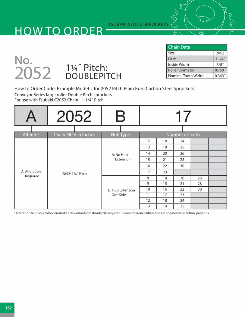
Chain DataSize 2052Pitch 1 1/4˝Inside Width 3/8˝Roller Diameter 0.750˝Nominal Tooth Width: 0.343˝
A 2052 B 17Altered !! Chain Pitch in Inches Hub Type Number of Teeth
A: Alteration Required
2052: 1¼˝ Pitch
A: No Hub Extension
12 18 24
13 19 25
14 20 26
15 21 28
16 22 30
17 23
B: Hub Extension One Side
8 14 20 269 15 21 28
10 16 22 3011 17 2312 18 2413 19 25
How to Order Code: Example Model # for 2052 Pitch Plain Bore Carbon Steel SprocketsConveyor Series large roller Double Pitch sprocketsFor use with Tsubaki C2052 Chain - 1 1/4" Pitch
No.1¼˝ Pitch: DOUBLE PITCH2052
HOW TO ORDERTSUBAKI STOCK SPROCKETS
!! Alteration field only to be denoted if a deviation from standard is required. Please reference Alterations in engineering section, page 182.
152

PLAIN BORE SPROCKET DIMENSIONSNo. 2052 Tsubaki Stock Sprockets
No. 2052 Plain Bore Sprocket Dia. Type “A” Plain Bore Type “B” Plain Bore
No. Teeth
Outside Dia.
Pitch Dia.
Caliper Dia.
Plain Bore
Wt. Lbs.
Plain Bore
MAX Bore *
Hub Dia. LTB Hub
TypeHub Style
Wt. Lbs.
8 3.770 3.266 2.516 N/A N/A 0.625 1.594 2.359 1.000 B S 1.38
9 4.190 3.655 2.850 N/A N/A 0.625 1.781 2.781 1.000 B S 1.92
10 4.600 4.045 3.295 N/A N/A 0.625 2.000 3.000 1.000 B S 2.30
11 5.010 4.437 3.642 N/A N/A 0.625 2.000 3.000 1.000 B S 2.54
12 5.420 4.830 4.080 0.719 1.58 0.750 2.000 3.000 1.250 B D 3.20
13 5.820 5.223 4.435 0.719 1.82 0.750 2.000 3.000 1.250 B D 3.48
14 6.230 5.617 4.867 0.719 2.28 0.750 2.000 3.000 1.250 B D 3.88
15 6.630 6.012 5.229 0.719 2.46 0.750 2.250 3.250 1.250 B D 4.46
16 7.030 6.407 5.657 0.719 2.88 0.750 2.250 3.250 1.250 B D 4.80
17 7.440 6.803 6.024 0.719 3.28 0.750 2.250 3.250 1.250 B D 5.34
18 7.840 7.198 6.448 0.719 3.64 0.750 2.250 3.250 1.250 B D 5.64
19 8.240 7.595 6.819 0.719 4.12 0.750 2.250 3.250 1.250 B D 6.04
20 8.640 7.991 7.241 0.719 4.72 0.750 2.250 3.250 1.250 B D 6.48
21 9.040 8.387 7.614 0.719 5.08 0.750 2.250 3.250 1.250 B D 7.00
22 9.440 8.783 8.033 0.719 5.20 0.750 2.250 3.250 1.250 B D 7.30
23 9.850 9.180 8.409 0.938 5.84 1.000 2.750 3.750 1.250 B D 8.66
24 10.250 9.577 8.827 0.938 6.70 0.938 2.750 3.750 1.250 B D 9.32
25 10.650 9.973 9.204 0.938 7.54 0.938 2.750 3.750 1.250 B D 10.30
26 11.050 10.370 9.620 0.938 8.24 0.938 2.750 3.750 1.250 B D 11.00
28 11.840 11.164 10.414 0.938 8.70 0.938 2.750 3.750 1.250 B D 11.70
30 12.640 11.958 11.208 0.938 9.92 0.938 2.750 3.750 1.250 B D 12.90
* Dimensions shown allow for standard keyway with set screw at 90 degreesN/A = Non applicable/Not Available as standard
TOOTH (NOMINAL) TOOTH (NOMINAL)TOOTH (NOMINAL)TOOTH (NOMINAL)
TYPE A STYLE DTYPE B
STYLE STYPE B
STYLE DTYPE C
OU
TSID
E DI
AMET
ER
OU
TSID
E DI
AMET
ERBO
RE
HU
B DI
AMET
ER
LTB
BORE
HU
B DI
AMET
ER
LTBLTB
OU
TSID
E DI
AMET
ERBO
RE
BORE
OU
TSID
E DI
AMET
ER
HU
B DI
AMET
ER
.343 NOMINAL .343 NOMINAL .343 NOMINAL
All dimensions in inches unless noted.
153www.tsubaki.ca
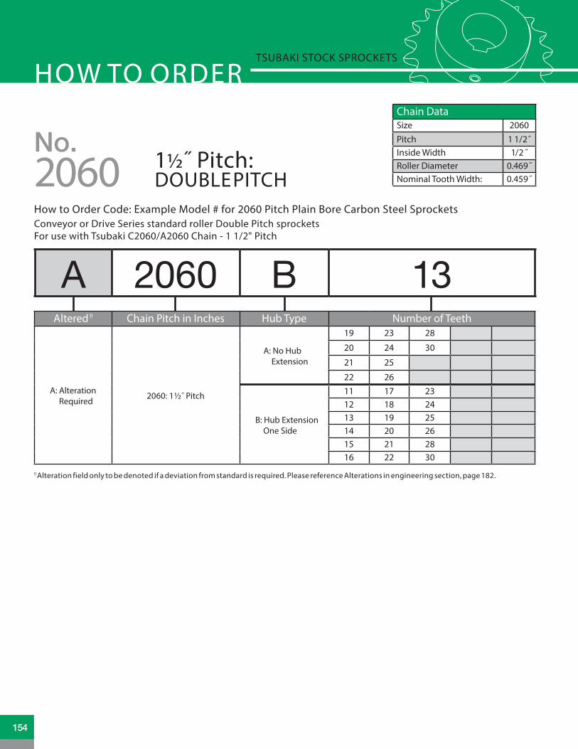
Chain DataSize 2060Pitch 1 1/2˝Inside Width 1/2 ˝Roller Diameter 0.469˝Nominal Tooth Width: 0.459˝
A 2060 B 13Altered !! Chain Pitch in Inches Hub Type Number of Teeth
A: Alteration Required
2060: 1½˝ Pitch
A: No Hub Extension
19 23 28
20 24 30
21 25
22 26
B: Hub Extension One Side
11 17 2312 18 2413 19 2514 20 2615 21 2816 22 30
How to Order Code: Example Model # for 2060 Pitch Plain Bore Carbon Steel SprocketsConveyor or Drive Series standard roller Double Pitch sprocketsFor use with Tsubaki C2060/A2060 Chain - 1 1/2" Pitch
No.1½˝ Pitch: DOUBLE PITCH2060
HOW TO ORDERTSUBAKI STOCK SPROCKETS
!! Alteration field only to be denoted if a deviation from standard is required. Please reference Alterations in engineering section, page 182.
154
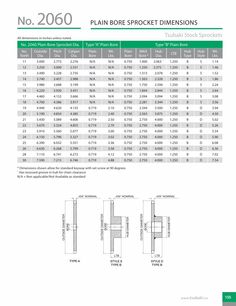
PLAIN BORE SPROCKET DIMENSIONSNo. 2060 Tsubaki Stock Sprockets
No. 2060 Plain Bore Sprocket Dia. Type “A” Plain Bore Type “B” Plain Bore
No. Teeth
Outside Dia.
Pitch Dia.
Caliper Dia.
Plain Bore
Wt. Lbs.
Plain Bore
MAX Bore *
Hub Dia. LTB Hub
TypeHub Style
Wt. Lbs.
11 3.000 2.773 2.276 N/A N/A 0.750 1.000 2.063 ¨ 1.250 B S 1.14
12 3.250 3.000 2.531 N/A N/A 0.750 1.250 2.375 ¨ 1.250 B S 1.46
13 3.490 3.228 2.735 N/A N/A 0.750 1.313 2.078 1.250 B S 1.52
14 3.740 3.457 2.988 N/A N/A 0.750 1.563 2.328 1.250 B S 1.86
15 3.980 3.688 3.199 N/A N/A 0.750 1.750 2.594 1.250 B S 2.24
16 4.220 3.920 3.451 N/A N/A 0.750 1.844 2.844 1.250 B S 2.64
17 4.460 4.152 3.666 N/A N/A 0.750 2.094 3.094 1.250 B S 3.08
18 4.700 4.386 3.917 N/A N/A 0.750 2.281 3.344 1.250 B S 3.56
19 4.940 4.620 4.135 0.719 2.10 0.750 2.344 3.500 1.250 B D 3.94
20 5.190 4.854 4.385 0.719 2.40 0.750 2.563 3.875 1.250 B D 4.50
21 5.430 5.089 4.606 0.719 2.50 0.750 2.750 4.000 1.250 B D 5.02
22 5.670 5.324 4.855 0.719 2.70 0.750 2.750 4.000 1.250 B D 5.26
23 5.910 5.560 5.077 0.719 3.00 0.750 2.750 4.000 1.250 B D 5.54
24 6.150 5.796 5.327 0.719 3.02 0.750 2.750 4.000 1.250 B D 5.90
25 6.390 6.032 5.551 0.719 3.36 0.750 2.750 4.000 1.250 B D 6.08
26 6.630 6.268 5.799 0.719 3.58 0.750 2.750 4.000 1.250 B D 6.36
28 7.110 6.741 6.272 0.719 4.12 0.750 2.750 4.000 1.250 B D 7.02
30 7.590 7.215 6.746 0.719 4.88 0.750 2.750 4.000 1.250 B D 7.54
TOOTH (NOMINAL) TOOTH (NOMINAL)TOOTH (NOMINAL)TOOTH (NOMINAL)
TYPE A STYLE DTYPE B
STYLE STYPE B
STYLE DTYPE C
OU
TSID
E DI
AMET
ER
OU
TSID
E DI
AMET
ERBO
RE
HU
B DI
AMET
ER
LTB
BORE
HU
B DI
AMET
ER
LTBLTB
OU
TSID
E DI
AMET
ERBO
RE
BORE
OU
TSID
E DI
AMET
ER
HU
B DI
AMET
ER
.459 NOMINAL .459 NOMINAL .459 NOMINAL
All dimensions in inches unless noted.
* Dimensions shown allow for standard keyway with set screw at 90 degrees¨ Has recessed groove in hub for chain clearanceN/A = Non applicable/Not Available as standard
155www.tsubaki.ca

Chain DataSize 2062Pitch 1 1/2˝Inside Width 3/8˝Roller Diameter 0.875˝Nominal Tooth Width: 0.459˝
A 2062 B 11Altered !! Chain Pitch in Inches Hub Type Number of Teeth
A: Alteration Required
2062: 1½˝ Pitch
A: No Hub Extension
12 18 24
13 19 25
14 20 26
15 21 28
16 22 30
17 23
B: Hub Extension One Side
8 14 20 269 15 21 28
10 16 22 3011 17 2312 18 2413 19 25
How to Order Code: Example Model # for 2062 Pitch Plain Bore Carbon Steel SprocketsConveyor Series large roller Double Pitch sprocketsFor use with Tsubaki C2062/A2062 Chain - 1 1/2" Pitch
No.1½˝ Pitch: DOUBLE PITCH2062
HOW TO ORDERTSUBAKI STOCK SPROCKETS
!! Alteration field only to be denoted if a deviation from standard is required. Please reference Alterations in engineering section, page 182.
156

PLAIN BORE SPROCKET DIMENSIONSNo. 2062 Tsubaki Stock Sprockets
No. 2062 Plain Bore Sprocket Dia. Type “A” Plain Bore Type “B” Plain Bore
No. Teeth
Outside Dia.
Pitch Dia.
Caliper Dia.
Plain Bore
Wt. Lbs.
Plain Bore
MAX Bore *
Hub Dia. LTB Hub
TypeHub Style
Wt. Lbs.
8 4.520 3.920 3.045 N/A N/A 0.750 1.844 2.844 1.250 B S 2.60
9 5.020 4.386 3.444 N/A N/A 0.750 2.281 3.344 1.250 B S 3.48
10 5.520 4.854 3.979 N/A N/A 0.750 2.563 3.828 1.250 B S 4.54
11 6.010 5.324 4.395 N/A N/A 0.750 2.750 4.000 1.250 B S 5.20
12 6.500 5.796 4.921 0.719 2.98 0.750 2.750 4.000 1.250 B D 5.70
13 6.990 6.268 5.347 0.719 3.60 0.750 2.750 4.000 1.250 B D 6.28
14 7.470 6.741 5.866 0.719 4.02 0.750 2.750 4.000 1.250 B D 6.82
15 7.960 7.215 6.300 0.719 4.76 0.750 2.750 4.000 1.250 B D 7.48
16 8.440 7.689 6.814 0.719 5.70 0.750 2.750 4.000 1.250 B D 8.18
17 8.920 8.163 7.253 0.938 6.16 1.000 2.750 4.000 1.250 B D 8.82
18 9.410 8.638 7.763 0.938 6.96 1.000 2.750 4.000 1.250 B D 9.36
19 9.890 9.113 8.207 0.938 8.00 1.000 2.750 4.250 1.250 B D 11.10
20 10.370 9.589 8.714 0.938 8.46 0.938 2.750 4.250 1.250 B D 11.66
21 10.850 10.064 9.161 0.938 8.93 0.938 2.750 4.250 1.250 B D 13.24
22 11.330 10.540 9.665 0.938 10.74 0.938 2.750 4.250 1.250 B D 13.78
23 11.810 11.016 10.115 0.938 11.64 0.938 2.750 4.250 1.250 B D 14.90
24 12.290 11.492 10.617 0.938 12.64 0.938 2.750 4.250 1.250 B D 15.56
25 12.770 11.968 11.070 0.938 13.78 0.938 2.750 4.250 1.250 B D 16.80
26 13.250 12.444 11.569 0.938 15.00 0.938 2.750 4.250 1.750 B D 20.20
28 14.210 13.397 12.522 1.250 17.32 1.250 2.750 4.250 1.750 B D 21.86
30 15.170 14.350 13.475 1.250 19.50 1.250 2.750 4.250 1.750 B D 26.00
* Dimensions shown allow for standard keyway with set screw at 90 degreesN/A = Non applicable/Not Available as standard
TOOTH (NOMINAL) TOOTH (NOMINAL)TOOTH (NOMINAL)TOOTH (NOMINAL)
TYPE A STYLE DTYPE B
STYLE STYPE B
STYLE DTYPE C
OU
TSID
E DI
AMET
ER
OU
TSID
E DI
AMET
ERBO
RE
HU
B DI
AMET
ER
LTB
BORE
HU
B DI
AMET
ER
LTBLTB
OU
TSID
E DI
AMET
ERBO
RE
BORE
OU
TSID
E DI
AMET
ER
HU
B DI
AMET
ER
.459 NOMINAL .459 NOMINAL .459 NOMINAL
All dimensions in inches unless noted.
157www.tsubaki.ca

Chain DataSize 2080Pitch 2 ̋Inside Width 5/8˝Roller Diameter 0.625˝Nominal Tooth Width: 0.575˝
A 2080 B 20Altered !! Chain Pitch in Inches Hub Type Number of Teeth
A: Alteration Required
2080: 2˝ Pitch
A: No Hub Extension
16 21 26
17 22 28
18 23 30
19 24
20 25
B: Hub Extension One Side
11 17 2312 18 2413 19 2514 20 2615 21 2816 22 30
How to Order Code: Example Model # for 2080 Pitch Plain Bore Carbon Steel SprocketsConveyor Series large roller Double Pitch sprocketsFor use with Tsubaki C2080/A2080 Chain - 2" Pitch
No.2˝ Pitch: DOUBLE PITCH2080
HOW TO ORDERTSUBAKI STOCK SPROCKETS
!! Alteration field only to be denoted if a deviation from standard is required. Please reference Alterations in engineering section, page 182.
158

PLAIN BORE SPROCKET DIMENSIONSNo. 2080 Tsubaki Stock Sprockets
No. 2080 Plain Bore Sprocket Dia. Type “A” Plain Bore Type “B” Plain Bore
No. Teeth
Outside Dia.
Pitch Dia.
Caliper Dia.
Plain Bore
Wt. Lbs.
Plain Bore
MAX Bore *
Hub Dia. LTB Hub
TypeHub Style
Wt. Lbs.
11 4.010 3.694 3.074 N/A N/A 1.000 1.500 2.813 ¨ 1.625 B S 2.50
12 4.330 4.000 3.375 N/A N/A 1.000 1.688 3.125 ¨ 1.625 B S 3.20
13 4.660 4.304 3.647 N/A N/A 1.000 1.781 2.781 1.500 B S 3.20
14 4.980 4.610 3.985 N/A N/A 1.000 2.125 3.125 1.500 B S 4.00
15 5.300 4.917 4.265 N/A N/A 1.000 2.281 3.453 1.500 B S 4.80
16 5.630 5.226 4.601 0.938 3.10 1.000 2.531 3.797 1.500 B D 5.70
17 5.960 5.536 4.888 0.938 3.40 1.000 2.750 4.000 1.500 B D 6.40
18 6.270 5.848 5.223 0.938 3.80 1.000 2.750 4.250 1.500 B D 7.40
19 6.590 6.160 5.513 0.938 4.30 1.000 2.750 4.250 1.500 B D 7.70
20 6.910 6.472 5.845 0.938 4.80 1.000 2.750 4.250 1.500 B D 8.30
21 7.230 6.785 6.141 0.938 5.30 1.000 2.750 4.250 1.750 B D 9.40
22 7.560 7.099 6.474 0.938 5.80 1.000 2.750 4.250 1.750 B D 10.00
23 7.880 7.413 6.770 0.938 6.40 1.000 2.750 4.250 1.750 B D 10.50
24 8.200 7.727 7.102 0.938 7.10 1.000 2.750 4.250 1.750 B D 11.10
25 8.520 8.042 7.401 0.938 7.50 1.000 2.750 4.250 1.750 B D 12.00
26 8.840 8.357 7.732 1.188 8.30 1.250 3.250 4.750 2.000 B D 14.80
28 9.480 8.988 8.363 1.188 9.20 1.188 3.250 4.750 2.000 B D 16.60
30 10.110 9.620 8.995 1.188 10.70 1.188 3.250 4.750 2.000 B D 17.80
* Dimensions shown allow for standard keyway with set screw at 90 degrees¨ Has recessed groove in hub for chain clearanceN/A = Non applicable/Not Available as standard
TOOTH (NOMINAL) TOOTH (NOMINAL)TOOTH (NOMINAL)TOOTH (NOMINAL)
TYPE A STYLE DTYPE B
STYLE STYPE B
STYLE DTYPE C
OU
TSID
E DI
AMET
ER
OU
TSID
E DI
AMET
ERBO
RE
HU
B DI
AMET
ER
LTB
BORE
HU
B DI
AMET
ER
LTBLTB
OU
TSID
E DI
AMET
ERBO
RE
BORE
OU
TSID
E DI
AMET
ER
HU
B DI
AMET
ER
.575 NOMINAL .575 NOMINAL .575 NOMINAL
All dimensions in inches unless noted.
159www.tsubaki.ca

Chain DataSize 2082Pitch 2 ̋Inside Width 5/8˝Roller Diameter 1.125˝Nominal Tooth Width: 0.575˝
A 2082 B 28Altered !! Chain Pitch in Inches Hub Type Number of Teeth
A: Alteration Required
2082: 2˝ Pitch
A: No Hub Extension
11 17 23
12 18 24
13 19 25
14 20 26
15 21 28
16 22 30
B: Hub Extension One Side
8 14 20 269 15 21 28
10 16 22 3011 17 2312 18 2413 19 25
How to Order Code: Example Model # for 2082 Pitch Plain Bore Carbon Steel SprocketsConveyor Series large roller Double Pitch sprocketsFor use with Tsubaki C2082/A2082 Chain - 2" Pitch
No.2˝ Pitch: DOUBLE PITCH2082
HOW TO ORDERTSUBAKI STOCK SPROCKETS
!! Alteration field only to be denoted if a deviation from standard is required. Please reference Alterations in engineering section, page 182.
160

PLAIN BORE SPROCKET DIMENSIONSNo. 2082 Tsubaki Stock Sprockets
No. 2082 Plain Bore Sprocket Dia. Type “A” Plain Bore Type “B” Plain Bore
No. Teeth
Outside Dia.
Pitch Dia.
Caliper Dia.
Plain Bore
Wt. Lbs.
Plain Bore
MAX Bore *
Hub Dia. LTB Hub
TypeHub Style
Wt. Lbs.
8 6.030 5.226 4.101 N/A N/A 1.000 2.531 3.797 1.750 B S 6.40
9 6.700 5.848 4.634 N/A N/A 1.000 2.750 4.250 1.750 B S 8.20
10 7.360 6.472 5.347 N/A N/A 1.000 2.750 4.250 1.750 B S 9.20
11 8.010 7.099 5.902 0.938 5.70 1.000 2.750 4.250 1.750 B D 10.10
12 8.660 7.727 6.602 0.938 6.80 1.000 2.750 4.250 1.750 B D 11.20
13 9.310 8.357 7.171 1.188 7.70 1.250 3.250 4.750 2.000 B D 15.00
14 9.960 8.988 7.863 1.188 9.10 1.250 3.250 4.750 2.000 B D 15.80
15 10.610 9.620 8.442 1.188 10.70 1.188 3.250 4.750 2.000 B D 17.80
16 11.250 10.252 9.127 1.188 12.40 1.188 3.250 4.750 2.000 B D 19.30
17 11.900 10.885 9.713 1.188 14.10 1.188 3.250 4.750 2.000 B D 21.40
18 12.540 11.512 10.393 1.188 15.40 1.188 3.250 4.750 2.000 B D 22.90
19 13.190 12.151 10.985 1.188 18.00 1.188 3.250 4.750 2.000 B D 24.40
20 13.830 12.785 11.660 1.188 19.20 1.188 3.250 4.750 2.000 B D 26.70
21 14.470 13.419 12.256 1.250 20.80 1.250 3.250 4.750 2.000 B D 28.40
22 15.110 14.053 12.928 1.250 23.70 1.250 3.250 4.750 2.000 B D 32.20
23 15.750 14.688 13.528 1.250 24.90 1.250 3.250 4.750 2.000 B D 34.90
24 16.390 15.323 14.198 1.250 27.60 1.250 3.250 4.750 2.000 B D 37.80
25 17.030 15.958 14.801 1.250 30.20 1.250 3.250 4.750 2.000 B D 39.60
26 17.670 16.593 15.468 1.250 32.80 1.250 3.500 5.250 2.000 B D 41.50
28 18.950 17.863 16.738 1.250 38.60 1.250 3.500 5.250 2.000 B D 47.70
30 20.230 19.134 18.009 1.250 43.80 1.250 3.500 5.250 2.000 B D 54.50
* Dimensions shown allow for standard keyway with set screw at 90 degreesN/A = Non applicable/Not Available as standard
TOOTH (NOMINAL) TOOTH (NOMINAL)TOOTH (NOMINAL)TOOTH (NOMINAL)
TYPE A STYLE DTYPE B
STYLE STYPE B
STYLE DTYPE C
OU
TSID
E DI
AMET
ER
OU
TSID
E DI
AMET
ERBO
RE
HU
B DI
AMET
ER
LTB
BORE
HU
B DI
AMET
ER
LTBLTB
OU
TSID
E DI
AMET
ERBO
RE
BORE
OU
TSID
E DI
AMET
ER
HU
B DI
AMET
ER
.575 NOMINAL .575 NOMINAL .575 NOMINAL
All dimensions in inches unless noted.
161www.tsubaki.ca

A C2040 RP -10Altered !! Double Plus Chain Pitch Chain Type: Number of Teeth*
A: Alteration Required
C2030
VRP: Plastic Roller Type 10: 10 Teeth
C2040
C2050
C2060
C2080
No. Teeth Chain Pitch
OutsideDia. (Do)
Pitch Dia. (Dp)
Plain Bore (d)
Hub Dia. (DH)
Hub Length
(L)
Hub Type
Tooth Thickness
(T)M Wt.
Lbs.
10 C2030 2.480 2.427 0.500 1.457 0.984 B 0.118 0.602 0.44
10 C2040 3.346 3.326 0.630 2.047 1.575 B 0.157 0.803 1.76
10 C2050 4.213 4.045 0.630 2.598 1.772 B 0.197 1.004 3.31
10 C2060 5.039 4.854 0.748 3.189 1.969 B 0.236 1.201 5.52
10 C2080 6.772 6.472 0.906 4.331 2.638 B 0.472 1.870 15.40
How to Order Code: Example Model # for Double Plus Carbon Steel SprocketsSprockets for Tsubaki Double Plus Chain Series VR, VRP, VR-SC and VRP-SC
Dimensional data in inches unless noted.
DOUBLE PLUS SPROCKETS
HOW TO ORDERTSUBAKI STOCK SPROCKETS
!! Alteration field only to be denoted if a deviation from standard is required. Please reference Alterations in engineering section, page 182.* Number of Teeth*: Double Plus sprockets are available in 10 tooth configuration only as stock. Please consult factory for other options.
TTM
L
ød
DOUBLE STRAND
D h D p D o
162

BUSHINGS, HUBS, IDLERS AND CHAIN TENSIONERS
www.tsubaki.ca
Bushings, Hubs, Idlers and Chain TensionersTAPER-LOCK® BushingsTAPER-LOCK® Weld-On HubsQD® BushingsQD® Weld-On HubsIdler SprocketsChain Tensioners
163164 - 167168 - 169170 - 173174 - 175176 - 178 179 - 180
163

A 2517 -1BAltered !! Bushing Number Bore Size
A: Alteration Required
1008 Blank = stock plain bore
1108 H 1/2" (0.500")
1210 I 9/16" (0.563")
1215 J 5/8" 90.625")
1310 K 11/16" (0.688")
1610 L 3/4" (0.750")
1615 M 13/16" (0.813")
2012 P 7/8" (0.875")
2517 R 15/16" (0.938")
2525 1 1" (1.000")
3020 1A 1-1/16" (1.063")
3030 1B 1-1/8" (1.125")
3535
4040
4545
5050
How to Order Code: Example Model # for TAPER-LOCK® Bushings
HOW TO ORDERTSUBAKI STOCK SPROCKETS
TAPER-LOCK® BUSHINGS
!! Alteration field only to be denoted if a deviation from standard is required. Please reference Alterations in engineering section, page 182.
Above are examples. There are more sizes available.
See chart on page 166.
TAPER-LOCK® is a registered trademark of Rockwell Automation.
Section A-A
164

TAPER-LOCK® BUSHINGS DIMENSIONS
Bushing No.
Bore RangeTorque
Capacity (lb-in)
A B C Wt. Lbs*Minimum
Max w/Standard Keyway
Max w/ Shallow Keyway
Max w/No Keyway
1008 0.500 0.875 1.000 1.000 1,200 1.386 0.875 1.328 0.20
1108 0.500 1.000 1.125 1.125 1,300 1.511 0.875 1.453 0.251210 0.500 1.250 1.250 1.250 3,600 1.875 1.000 1.750 0.551215 0.500 1.250 1.250 1.250 3,550 1.875 1.500 1.750 0.701310 0.500 1.375 1.438 1.438 3,850 2.000 1.000 1.875 0.701610 0.500 1.625 1.688 1.688 4,300 2.250 1.000 2.125 0.751615 0.500 1.625 1.688 1.688 4,300 2.250 1.500 2.125 1.002012 0.500 2.000 2.125 2.125 7,150 2.750 1.250 2.625 1.402517 0.500 2.438 2.688 2.688 11,600 3.375 1.750 3.250 3.202525 0.750 2.375 2.688 2.688 11,300 3.375 2.500 3.250 4.303020 0.875 3.000 3.250 3.250 24,000 4.250 2.000 4.000 5.803030 0.938 3.000 3.250 3.250 24,000 4.250 3.000 4.000 8.003535 1.188 3.500 3.938 3.938 44,800 5.000 3.500 4.830 11.004040 1.438 4.000 4.438 4.438 77,300 5.750 4.000 5.540 17.004545 1.938 4.500 4.938 4.938 110,000 6.375 4.500 6.130 24.005050 2.438 5.000 5.313 5.313 126,000 7.000 5.000 6.720 32.00
Bushing No.
Locking Screws (F) Clearance L* Clearance M#Hex Key Torque
in./lbsSize Qt. Std. Hey Key Short Hex Key Std. Hey Key Short Hex Key
1008 .250 X .500 2 1.125 0.625 1.250 0.750 55
1108 .250 X .500 2 1.125 0.625 1.250 0.750 551210 .375 X .625 2 1.375 0.813 1.625 1.063 1751215 .375 X .625 2 1.375 0.813 1.625 1.063 1751310 .375 X .625 2 1.375 0.813 1.625 1.063 1751610 .375 X .625 2 1.375 0.813 1.625 1.063 1751615 .375 X .625 2 1.375 0.813 1.625 1.063 1752012 .438 X .875 2 1.563 0.938 2.000 1.375 2802517 .500 X 1.000 2 1.625 1.000 2.250 1.625 4302525 .500 X 1.000 2 1.625 1.000 2.250 1.625 4303020 .625 X 1.250 2 1.813 1.188 2.688 2.063 8003030 .625 X 1.250 2 1.813 1.188 2.688 2.063 8003535 .500 X 1.500 3 2.000 1.313 3.375 2.688 10004040 .625 X 1.750 3 2.375 1.625 4.125 3.375 17004545 .750 X 2.000 3 2.625 1.938 4.750 4.063 24505050 .875 X 2.250 3 2.813 2.313 5.250 4.813 3100
* Bushing weight changes with bore size. Weight depicted reflects approximate weight.NOTE: Torque Capacity shown is for light starting and steady running. For more sever applications apply Service Factor as needed.
* Space required to tighten bushing. Also space required to loosen screws to permit removal of hub by puller. # Space required to remove bushing using jackscrews - no puller required Short Hex Key = Standard hex key cut to minimum usable length.
All dimensions in inches unless noted.
All dimensions in inches unless noted.
165www.tsubaki.ca

TAPER-LOCK® BUSHINGS
Bore Size
in Inches
Item Code
Bushing Number
1008
1108
1210
1215
1310
1610
1615
2012
2517
2525
3020
3030
3535
4040
4545
5050
1/2" H • • • • • • • • •9/16" I • • • • • • • •5/8" J • • • • • • • • •
11/16" K • • • • • • • • •3/4" L • • • • • • • • • •
13/16" M • • • • • • • • •7/8" P • • • • • • • • • • •
15/16" R S • • • • • • • • • • •1" 1 S • • • • • • • • • • •
1-1/16" 1A S • • • • • • • •1-1/8" 1B S • • • • • • • • • •
1-3/16" 1C • • • • • • • • • • •1-1/4" 1D • • • • • • • • • • •
1-5/16" 1E • • • • • • •1-3/8" 1F • • • • • • • • •
1-7/16" 1G S • • • • • • • • •1-1/2" 1H • • • • • • • • •
1-9/16" 1I S S • • • •1-5/8" 1J S S • • • • • • •
1-11/16" 1K S S • • • • • • •1-3/4" 1L • • • • • • •
1-13/16" 1M • • • • •1-7/8" 1P • • • • • • •
1-15/16" 1R S • • • • • • •2" 2 S • • • • • • •
2-1/16" 2A • • • •2-1/8" 2B S • • • • •
2-3/16" 2C • • • • • •2-1/4" 2D • • • • • •
2-5/16" 2E S S • •2-3/8" 2F S S • • • •
2-7/16" 2G S S • • • • • •2-1/2" 2H S S • • • •
2-9/16" 2I • •2-5/8" 2J S • • • •
2-11/16" 2K S • • • •2-3/4" 2L • • • •
2-13/16" 2M S •2-7/8" 2P S S • • •
2-15/16" 2R S S • • • •3" 3 S S • • •
3-1/8" 3B S S • • •3-3/16" 3C S S • •3-1/4" 3D S S • • •
3-5/16" 3E S3-3/8" 3F S • •
3-7/16" 3G S • •3-1/2" 3H S • •3-5/8" 3J S • • •
3-11/16" 3K S S3-3/4" 3L S S •3-7/8" 3P S S • •
3-15/16" 3R S S • •4" 4 S • •
4-1/8" 4B S • •4-3/16" 4C •4-1/4" 4D S •4-3/8" 4F • •
4-7/16" 4G S • •4-1/2" 4H S •4-3/4" 4P S S
4-15/16" 4R S S5" 5 S
• Denotes stocking item S = Shallow keyway in hubSee page 194 for Shallow keyway dimensions.
166

TAPER-LOCK® BUSHING INSTALLATION AND REMOVAL
TAPER-LOCK® Bushing Installation
TAPER-LOCK® Bushing Removal
1 Clean and degrease the bore and tapered surface of the bushing and the tapered bore of the pulley/hub/sprocket.2 Insert the bushing into the pulley hub sprocket bore and line up the holes ( alf threaded holes must line up the half straight non-threaded holes).3 Lightly oil the locking screws and insert but do not tighten yet.4 hen using a key, it should be fitted to the shaft keyway. There should be a top clearance between the key and the keyway in the mating bushing.5 Clean and degrease the shaft. Fit pulley/hub/sprocket onto the shaft and locate in the desired position.6 Using a hexagon socket wrench, gradually tighten the locking screws in accordance with the required tightening torque.7 When the drive has been operating under load for a short period, approximately 30 to 60 minutes, stop the equipment and check that the screws remain at the required tightening torque. Adjust if necessary.8 To avoid the ingress of dirt, fill all empty holes with grease.
A Remove any loading to the equipment to enable a safe removal of components. B Slacken and remove all locking screws. C Add lubricant to the previously removed screws and insert into jack-out hole/holes in the bushing. D Tighten the screws uniformly and alternately until the bushing is loose and the pulley/hub/sprocket can be moved freely on the shaft. E Remove the bushing pulley hub sprocket assembly from the shaft.
TAPER-LOCK® is a registered trademark of Rockwell Automation. 167www.tsubaki.ca

TAPER-LOCK® WELD-ON HUBS
Model # Use with Bushing # D P L T Wt.
Lbs
35TL1 1610 3.000 2.875 1.000 0.141 0.80
41TL1 1610 3.000 2.875 1.000 0.219 0.8040TL1 1610 3.000 2.875 1.000 0.250 0.8040TL2 2012 3.625 3.438 1.250 0.250 1.5040TL3 2517 4.250 4.125 1.750 0.250 2.7050TL1 2012 3.625 3.438 1.250 0.313 1.5050TL2 2517 4.250 4.125 1.750 0.313 2.7060TL1 2012 3.625 3.438 1.250 0.438 1.5060TL2 2517 4.250 4.125 1.750 0.438 2.7080TL1 2012 3.625 3.438 1.250 0.563 1.5080TL2 2517 4.250 4.125 1.750 0.563 2.7080TL3 3020 5.250 5.000 2.000 0.563 4.30
100TL1 2517 4.500 4.125 1.750 0.688 2.70100TL2 3020 5.250 5.000 2.000 0.688 4.30120TL1 2517 4.250 4.000 1.750 0.875 2.60120TL2 3020 5.250 5.000 2.000 0.875 4.20120TL3 3535 6.500 6.500 * 3.500 - 13.00140TL1 4040 7.750 7.750 * 4.000 - 25.00160TL1 3020 5.250 5.000 2.000 1.125 4.00160TL2 3535 6.500 6.250 3.500 1.125 12.60160TL3 4545 8.750 8.750 * 4.500 - 42.00
Tsubaki offers the most complete line of TAPER-LOCK® weld-on hubs for insertion and welding to produce “B” type sprockets, sheaves, and other applications without hub protrusion. To provide greater strength for this type of shaft locking mechanism and to reduce heat distortion caused by welding, these hubs are dimensionally interchangeable with our sprocket items.
Special dimension hubs are available per your application requirements on a Made-To-Order basis. All stock Tsubaki hubs are made from 1045 steel bar stock. No powdered or sintered metal is used. The TAPER-LOCK® weld-on hubs listed below include the appropriate tapered bores and mounting holes to mate with Tsubaki sprockets and other sprocket manufactures that conform to ANSI speci-fications.
TAPER-LOCK® WELD-ON HUBS
T
DP
LAll dimensions in inches unless noted.
* These items have no step on the hubs.
TAPER-LOCK® is a registered trademark of Rockwell Automation.168

TAPER-LOCK® WELD-ON HUBS
Hub Number
Use with Bushing # A B C D F G H J K Wt.
Lbs
W12 1215 2.875 1.500 0.375 0.625 0.375 2.500 2.375 1.875 2.625 1.30
W16 1615 3.250 1.500 0.375 0.625 0.375 2.875 2.750 2.375 3.000 1.50W25 2517 4.875 1.750 0.500 0.750 0.375 4.375 4.250 3.375 4.625 4.00W30 3030 5.500 3.000 0.750 0.750 0.250 5.125 4.813 4.125 5.000 8.60W35 3535 6.750 3.500 1.250 1.000 0.375 6.250 5.938 5.000 6.000 15.00W40 4040 7.750 4.000 1.500 1.000 0.375 7.250 6.875 5.750 7.000 29.00W45 4545 8.750 4.500 1.750 1.000 0.375 8.000 7.625 6.375 8.000 42.00
TAPER-LOCK® type W weld-on hubs are designed for use in applications such as welding to plate sprockets, pulleys, and agitators. Each is made of steel, drilled, tapped, and taper bored for TAPER-LOCK® bushings. The W-series Weld-On Hubs are generally used for severe duty applications.
TAPER-LOCK® TYPE W WELD-ON HUBS
G H AKJ
B
C D
F
All dimensions in inches unless noted.
169www.tsubaki.ca

How to Order Code: Example Model # for QD® Bushings
HOW TO ORDERTSUBAKI STOCK SPROCKETS
QD® BUSHINGS
BUSHINGS M TO PBUSHINGS JA TO JBUSHINGS M TO N
D
A
B
L
FG
A SDS -1BAltered !! QD® Bushing Bore Size
A: Alteration Required
JA Blank = stock plain boreSH H 1/2" (0.500")
SDS I 9/16" (0.563")
SDS J 5/8" (0.625")
SK K 11/16" (0.688")
SF L 3/4" (0.750")
E M 13/16" (0.813")
F P 7/8" (0.875")
J R 15/16" (0.938")
M 1 1" (1.000")
N 1A 1-1/16" (1.063")
P 1B 1-1/8" (1.125")
Above are examples. There are more sizes available. Please see QD® Bushing selection chart on pages 172 and 173.!! Alteration �eld only to be denoted if a deviation from standard is required.
Please reference Alterations in engineering section, page 182.
QD® is a registered trademark of, and is used under license agreement from Emerson Electric Co.170

QD® Bushing Dimensional Information
QD® Bushing
Bore Range Torque Capacity
(lb-in)A B D F G L Wt.
LbsMin.Max w/
Standard Keyway
Max w/ Shallow Keyway
Max w/No Keyway
JA 0.500 1.000 1.188 1.250 1,000 0.375 1.375 2.000 0.563 0.125 1.063 0.80SH 0.500 1.375 1.625 1.688 3,500 0.438 1.871 2.625 0.813 0.125 1.313 0.70
SDS 0.500 1.625 1.938 2.000 5,000 0.438 2.187 3.188 0.760 0.125 1.313 1.00SD 0.500 1.625 1.938 2.000 5,000 0.438 2.187 3.188 1.250 0.125 1.813 1.20SK 0.500 2.125 2.500 2.625 7,000 0.563 2.812 3.875 1.250 0.125 1.938 2.10SF 0.500 2.313 2.938 2.938 11,000 0.625 3.125 4.625 1.250 0.125 2.063 3.10E 0.875 2.875 3.500 - 20,000 0.873 3.834 6.000 1.625 0.250 2.750 7.10F 1.000 3.250 3.938 4.000 30,000 0.938 4.437 6.625 2.500 0.344 3.750 8.70J 1.500 3.750 4.500 - 45,000 1.125 5.148 7.250 3.188 0.375 4.625 16.80
M 2.000 4.750 5.500 - 85,000 1.250 6.500 9.000 5.188 0.400 6.750 56.00N 2.438 5.000 6.000 - 150,000 1.500 7.000 10.000 6.250 0.563 8.125 68.00P 2.938 5.938 7.000 - 250,000 1.750 8.250 11.750 7.250 0.625 9.375 120.00
QD® Bushing
Cap Screws Bolt Torque (FT. LBS.)Size Quantity Req. Bolt Circle*
JA 10 - 24 x 1 3 1.656 5SH 1/4 x 1 3/8 3 2.250 9
SDS 1/4 x 1 3/8 3 2.688 9SD 1/4 x 1 7/8 3 2.688 9SK 5/16 x 2 3 3.313 15SF 3/8 x 2 3 3.875 30E 1/2 x 2 3/4 3 5.000 60F 9/16 x 3 5/8 3 5.625 75J 5/8 x 4 1/2 3 6.250 135
M 3/4 x 6 3/4 4 7.875 225N 7/8 x 8 4 8.500 300P 1 x 9 1/2 4 10.000 450
QD® BUSHINGS
All dimensions in inches unless noted.
All dimensions in inches unless noted.
171www.tsubaki.ca

QD® BUSHING SELECTION CHART
S = Shallow keyway in hub N = No keyway in hub
QD® BushingBore Size in Inches Item Code JA SH SDS SD SK SF E F J M N P
1/2" H • • • • • •9/16" I • • • • • •5/8" J • • • • • •
11/16" K • • • • • •3/4" L • • • • • •
13/16" M • • • • • •7/8" P • • • • • • •
15/16" R • • • • • • •1" 1 • • • • • • • •
1-1/16" 1A S • • • • • • •1-1/8" 1B S • • • • • • •
1-3/16" 1C S • • • • • • •1-1/4" 1D N • • • • • • •
1-5/16" 1E • • • • • • •1-3/8" 1F • • • • • • •
1-7/16" 1G S • • • • • •1-1/2" 1H S • • • • • • •
1-9/16" 1I S • • • • • • •1-5/8" 1J S • • • • • • •
1-11/16" 1K N S S • • • • •1-3/4" 1L S S • • • • •
1-13/16" 1M S S • • • • •1-7/8" 1P S S • • • • •
1-15/16" 1R S S • • • • •2" 2 N N • • • • • •
2-1/16" 2A • • • • • •2-1/8" 2B • • • • • •
2-3/16" 2C S • • • • •2-1/4" 2D S • • • • •
2-5/16" 2E S • • • • •2-3/8" 2F S S • • • •
2-7/16" 2G S S • • • • •2-1/2" 2H S S • • • • •
2-9/16" 2I N S • • • • •2-5/8" 2J N S • • • • •
2-11/16" 2K S • • • • •2-3/4" 2L S • • • • •
2-13/16" 2M S • • • • •2-7/8" 2P S • • • • •
2-15/16" 2R S S • • • •3" 3 S • • • •
3-1/16" 3A S • • • •3-1/8" 3B S • • • •
3-3/16" 3C S • • • •3-1/4" 3D S • • • •
3-5/16" 3E S • • • •3-3/8" 3F S S • • •
3-7/16" 3G S S • • • •3-1/2" 3H S S • • • •
3-9/16" 3I S • • • •3-5/8" 3J S • • • •
3-11/16" 3K S • • • •3-3/4" 3L S • • • •
See page 195 for Shallow keyway dimensions.
172

QD® BUSHING SELECTION CHART
S = Shallow keyway in hub N = No keyway in hub
QD® BushingBore Sizein Inches Item Code JA SH SDS SD SK SF E F J M N P
3-13/16" 3M S • • • •3-7/8" 3P S S • • •
3-15/16" 3R S S • • •4" 4 N S • • •
4-1/16" 4A S • • •4-1/8" 4B S • • •
4-3/16" 4C S • • •4-1/4" 4D S • • •
4-5/16" 4E S • • •4-3/8" 4F S • • •
4-7/16" 4G S • • •4-1/2" 4H S • • •
4-9/16" 4I • • •4-5/8" 4J • • •
4-11/16" 4K • • •4-3/4" 4L • • •
4-13/16" 4M • • • 4-7/8" 4P S • •
4-15/16" 4R S • •5" 5 S • •
5-1/16" 5A S • •5-1/8" 5B S S •
5-3/16" 5C S S •5-1/4" 5D S S •
5-5/16" 5E S S •5-3/8" 5F S S •
5-7/16" 5G S S •5-1/2" 5H S S •
5-9/16" 5I S •5-5/8" 5J S •
5-11/16" 5K S •5-3/4" 5L S •
5-13/16" 5M S •5-7/8" 5 S •
5-15/16" 5R S •6" 6 S S
6-1/16" 6A S6-1/8" 6B S
6-3/16" 6C S6-1/4" 6D S
6-5/16" 6E S6-3/8" 6F S
6-7/16" 6G S6-1/2" 6H S
6-9/16" 6I S6-5/8" 6J S
6-11/16" 6K S6-3/4" 6L S
6-13/16" 6M S6-7/8" 6P S
6-15/16" 6R S7" 7 S
See page 195 for Shallow keyway dimensions.
QD® is a registered trademark of, and is used under license agreement from Emerson Electric Co. 173www.tsubaki.ca

QD® WELD-ON HUBS
Catalog Number
Use with Bushing #
Dim.D
Dim.P
Dim.L
Dim.T
Hub Type
Wt. Lbs.
35SHW SH 3.00 2.875 0.813 0.141 B .90
40SDSW SDS 3.500 3.125 0.750 0.250 B 1.00
40SKW SK 4.250 3.875 1.250 0.250 B 2.40
50SDSW SDS 3.625 3.438 0.750 0.313 B 1.00
50SKW SK 4.250 4.125 1.250 0.313 B 2.40
50SFW SF 5.000 4.625 1.250 0.313 B 3.70
60SDSW SDS 3.500 3.125 0.750 0.438 B 1.00
60SKW SK 4.250 3.875 1.250 0.438 B 2.40
60SFW SF 5.000 4.625 1.250 0.438 B 3.60
60EW E 6.250 5.875 1.625 0.438 B 7.80
80SFW SF 5.000 4.625 1.250 0.563 B 3.50
80EW E 6.250 5.875 1.625 0.563 C 7.70
80FW F 7.000 6.625 2.500 0.563 C 14.70
100EWB E 6.250 5.875 1.625 0.688 B 7.50
100EWC E 6.250 5.875 1.625 0.688 C 7.50
100FW F 7.000 6.625 2.500 0.688 C 14.60
120EW E 6.250 5.875 1.625 0.875 B 7.40
120FW F 7.000 6.625 2.500 0.875 C 14.30
120JW J 8.000 7.500 3.188 0.875 C 23.70
160FW F 7.000 6.625 2.500 1.094 B 14.00
160JW J 8.000 7.500 3.188 1.125 C 23.30
160MW M 10.000 9.500 5.188 2.250 C1 59.30
Tsubaki offers the most complete line of QD®” Style weld-on hubs for insertion and welding to produce “B” style sprockets, sheaves, and other applications. To provide greater strength for this type of shaft locking mechanism and reduce heat distortion caused by welding, these hubs are dimensionally the same as our sprocket items. Special dimensional hubs are available per your specifications on a made- to-order basis. All Tsubaki hubs are made from steel bar stock (not powdered or sintered metal). The QD®” Style Weld-On hubs listed below include appropriate tapered bores and mounting holes. QD® Weld-On hubs are manufactured with a step for assistance in locating the attached plate. This is shown as the “T” dimension and depending on the width of the plate, the result is either a B-style or C-style sprocket.
L
D
T
PL
D
T
Type C
Type B and Type C1
P
All dimensions in inches unless noted.
QD® is a registered trademark of, and is used under license agreement from Emerson Electric Co.174

NOTES
175www.tsubaki.ca

Tsubaki Stock Sprockets
IDLER SPROCKETS
Adjustable Idler Sprockets are used to: Obtain proper chain tension when either driving or driven shaft is not ad ustable. uide chain around an obstruction. Prevent whipping action in the slack span of chain. Bring about greater chain wrap around a small sprocket, particularly if it is the lower sprocket in a vertical drive.
Take up slack chain caused by normal chain wear. Provide for reversed direction of rotation of a sprocket in contact with the outside of the chain.
Idler sprockets should not rotate at greater speeds than are allowable for drive sprockets of the same diameter. They should be mounted in contact with the “slack” span of chain, whenever possible. Mount them on the outside of the chain when the arc of chain wrap on the smaller sprocket would otherwise be less than 120 . It is advisable that idler sprockets have at least three teeth in mesh with the chain. Inside mounted idlers usually account for quieter operation, especially if sprocket to sprocket centers are short and speed is moderately high.
W
LTB
OU
TSID
EDI
AMET
ER
BORE
1"
�1-1/2"
1/2"
�1/2"
E
1/4" ALEMITE
GREASE PORT HARD & GROUNDIDLER SHAFT
L
ADJUSTING SCREW
D
2G
KF (ADJUSTABLE)C MA
H
E
G PB
5/16
"J
OU
TSID
EDI
AMET
ER
BORE
HU
BDI
AMET
ER
STYLE S
LTB
Bronze Bushed Idler
Ball Bearing Idler
176

35 B 15TRoller Chain Pitch Size Hub Type Number of Teeth
35: 3/8" Pitch(example pitch size) B: Hub Extension One Side 15T: 15 Teeth
How to Order Code: Example Model # for Bronze Bushed Idler Sprockets for use with all steel chain
Bronze Bushed Idler Sprocket with Hardened TeethNote: Bronze Idler Sprockets should not exceed 2500-rpm and have a radial loading of 50 lbs. or less.
HOW TO ORDERTSUBAKI STOCK SPROCKETS
IDLER SPROCKETS - BRONZE BUSHED TYPE
ANSI Chain # Sprocket # # of
TeethSuggested
Tensioner # *Outside
DiameterHUB Type
Hub Diameter LTB Bushed
Bore Dia.Wt. Lbs.
35 35B15T 15 0 1.990 B 1.375 0.938 0.500 0.3235 35B21T 21 1 2.713 B 2.125 1.063 0.875 0.8240 40B13T 13 0 2.329 B 1.563 0.938 0.500 0.5240 40B19T 19 1 3.296 B 2.438 1.063 0.875 1.5041 41B13T 13 0 2.329 B 1.563 0.938 0.500 0.5241 41B19T 19 1 3.296 B 2.438 1.063 0.875 1.3050 50B13T 13 0 2.911 B 2.000 0.938 0.500 0.9750 50B17T 17 1 3.719 B 2.625 1.063 0.875 1.8060 60B15T 15 1 3.979 B 2.688 1.063 0.875 2.5060 60B17T 17 2 4.462 B 2.875 1.563 1.125 3.3080 80B15T 15 2 5.305 B 3.500 1.563 1.125 5.60
100 100B13T 13 2 5.821 B 4.000 1.563 1.125 5.70120 120B13T 13 2 6.986 B 4.500 1.563 1.125 13.00140 140B15T 15 3 9.283 B 5.750 2.500 1.750 27.30160 160B13T 13 3 9.318 B 5.750 2.500 1.750 26.40200 200B13T 13 3 11.642 B 5.750 2.500 1.750 58.00
All dimensions in inches unless noted.
1"
�1-1/2"
1/2"
�1/2"
E
1/4" ALEMITE
GREASE PORT HARD & GROUNDIDLER SHAFT
L
ADJUSTING SCREW
D
2G
KF (ADJUSTABLE)C MA
H
E
G PB
5/16
"J
OU
TSID
EDI
AMET
ER
BORE
HU
BDI
AMET
ER
STYLE S
LTB
Bronze Bushed Idler
* Please reference page 179 for chain tensioner information.
177www.tsubaki.ca
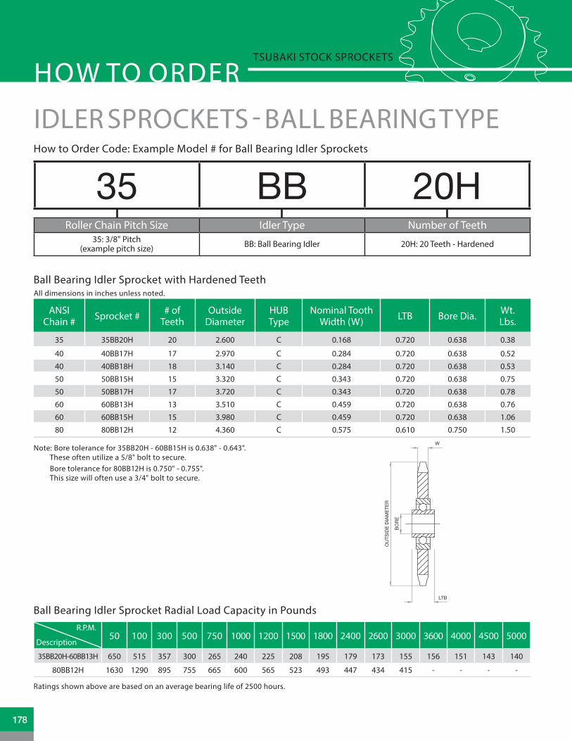
35 BB 20HRoller Chain Pitch Size Idler Type Number of Teeth
35: 3/8" Pitch(example pitch size) BB: Ball Bearing Idler 20H: 20 Teeth - Hardened
How to Order Code: Example Model # for Ball Bearing Idler Sprockets
Ball Bearing Idler Sprocket with Hardened Teeth
Ball Bearing Idler Sprocket Radial Load Capacity in Pounds
Note: Bore tolerance for 35BB20H - 60BB15H is 0.638" - 0.643". These often utilize a 5/8" bolt to secure. Bore tolerance for 80BB12H is 0.750" - 0.755". This size will often use a 3/4" bolt to secure.
Ratings shown above are based on an average bearing life of 2500 hours.
IDLER SPROCKETS - BALL BEARING TYPE
ANSI Chain # Sprocket # # of
TeethOutside
DiameterHUB Type
Nominal Tooth Width (W) LTB Bore Dia. Wt.
Lbs.
35 35BB20H 20 2.600 C 0.168 0.720 0.638 0.38
40 40BB17H 17 2.970 C 0.284 0.720 0.638 0.52
40 40BB18H 18 3.140 C 0.284 0.720 0.638 0.53
50 50BB15H 15 3.320 C 0.343 0.720 0.638 0.75
50 50BB17H 17 3.720 C 0.343 0.720 0.638 0.78
60 60BB13H 13 3.510 C 0.459 0.720 0.638 0.76
60 60BB15H 15 3.980 C 0.459 0.720 0.638 1.06
80 80BB12H 12 4.360 C 0.575 0.610 0.750 1.50W
LTB
OU
TSID
EDI
AMET
ER
BORE
HOW TO ORDERTSUBAKI STOCK SPROCKETS
50 100 300 500 750 1000 1200 1500 1800 2400 2600 3000 3600 4000 4500 5000
35BB20H-60BB13H 650 515 357 300 265 240 225 208 195 179 173 155 156 151 143 140
80BB12H 1630 1290 895 755 665 600 565 523 493 447 434 415 - - - -
Description
R.P.M.
All dimensions in inches unless noted.
178

Model Number A B C D E F G 2G H J K L M P Wt.
Lbs.0-B 5.875 1.500 5.250 0.500 1.000 2.500 0.281 0.375 2.813 1.313 1.375 1.250 0.375 0.750 1.00
1-B 9.000 2.000 8.125 0.875 1.750 4.500 0.344 0.500 4.000 1.625 1.750 1.500 0.500 1.000 2.50
2-B 13.000 3.000 11.875 1.125 1.875 6.000 0.563 0.750 5.688 2.156 2.875 2.000 0.625 1.500 6.00
3-B 14.000 4.000 12.625 1.750 3.125 6.000 0.563 0.750 6.250 2.188 3.250 2.000 0.750 2.000 12.00
CHAIN TENSIONER - MANUAL TYPE
Suggested Chain Size Manual Tensioner Model #
35 0-B
40, 41 0-B or 1-B
50 1-B
60 1-B
80 2-B
100 2-B
120 2-B
140 3-B
160 3-B
200 3-B
Proper chain tension is necessary to obtain acceptable chain life. Tensioners are designed to adjust the slack that is needed and develops as chains operate on a daily basis. Tensioners contribute to e cient, quiet operation of the drive assembly.
Selection Code:
Manual Tensioner
1"
�1-1/2"
1/2"
�1/2"
E
1/4" ALEMITE
GREASE PORT HARD & GROUNDIDLER SHAFT
L
ADJUSTING SCREW
D
2G
KF (ADJUSTABLE)C MA
H
E
G PB
5/16
"J
OU
TSID
EDI
AMET
ER
BORE
HU
BDI
AMET
ER
STYLE S
LTB
All dimensions in inches unless noted.
179www.tsubaki.ca

7.9
152
121
(21)
(15) 5075 44.5
6
125
104
(13)(12) 40
3265
51.5
71
46
143.
5
83S
32
17.5
max
.60
2-M8
M848.5
max
.35
28.5
17.5
2-M8
63
38
M6
S50
.5
91.5
φ12
26
197
Do
Dp
Do
12.7
φ12
25.4
Dp
TH-1
S1
BB Type OB Type
S2
TH-2
99
9
9
CHAIN TENSIONER - AUTOMATIC TYPEMAXTON series automated chain tensioners* Automatic tensioning * Stable vibration dampening * Operates on return side in any position * Simple adjusting * Quick and easy installation
AUTOMATIC TENSIONER
IDLER SPROCKETS FOR AUTOMATIC TENSIONER
Adapter (Note: S1 and S2 adapter work with both Tensioner TH1 and TH2)
Idler Sprocket
7.9
152
121
(21)
(15) 5075 44.5
6
125
104
(13)(12) 40
3265
51.5
71
46
143.
5
83S
32
17.5
max
.60
2-M8
M848.5
max
.35
28.5
17.5
2-M8
63
38
M6
S50
.5
91.5
φ12
26
197
Do
Dp
Do
12.7
φ12
25.4
Dp
TH-1
S1
BB Type OB Type
S2
TH-2
99
9
9
BB Type OB Type
Chain Size Automated Model Number Stroke (S)
Push-up Force (lbs.)
Min. Max
35 TH1 25.0 8.81 26.4440, 41 TH1 25.0 8.81 26.44
50 TH2 45.0 22.03 66.1060 TH2 45.0 22.03 66.1080 TH2 45.0 22.03 66.10
Chain Size
No. of Teeth
Pitch Diameter(in inches)
Model No.
SinteredBushing ID
BallBearing ID
35 20 2.397 SP-320-OB SP-320-BB40,41 15 2.405 SP-415-OB SP-415-BB
50 15 3.006 SP-515-OB SP-515-BB60 14 3.371 SP-604-OB SP-604-BB80 11 3.550 - SP-811-BB
All dimensions in millimeters unless noted.
180

ENGINEERING DATA
www.tsubaki.ca
Engineering DataAlterationsSprocket HardeningSprocket Tooth DimensionsSprocket Pitch Diameter ConstantsSprocket Speed RatiosSprocket DiametersStandard Keyway and Set ScrewsTAPER-LOCK® Shallow Keyway DimensionsQD® Shallow Keyway DimensionsMaintenance ChecklistSafety WarningOther Sprocket ConsiderationsTerms and Conditions of Sale
181182 - 185186187 188189190 - 192193
194195196197198 - 199200
181

ALTERATIONS
The term alteration applies to a modification change in configuration from standard for a stock sprocket. All Tsubaki sprockets can be “Altered” to meet select application requirements. The following provides a list of common alterations performed by Tsubaki to stock sprockets, and an explanation of what each is. In the event that the modification requested is not listed, it does not mean that the sprocket cannot be altered. owever, it may mean that the alteration in question would require the sprocket be Made-To-Order (MTO) to meet the ap-plication requirements at hand. Please consult a Tsubaki Customer Service Representative to review additional options available for altered and MTO sprockets.
Tsubaki standard keyway configuration facilitates use of industry standard square key stock in inch sizes with use of common set screws. The standard keyway location is center line of tooth +/- 0.015". Two set screws are furnished with finished bore sprockets. One set screw is placed directly over the keyway. The second set screw is placed at 90 degrees from the keyway set screw. Application requirements may demand a different keyway and set screw configuration than standard. Common alterations to standard keyway / set screw configurations include:
Keyway non center line of tooth Tapered keyway Multiple keyways Metric keyway Metric set screws Set screw location other than standard
Please see Figure 2 for standard keyway locations.
Reboring is a process of changing the dimension or configuration of the sprocket inner hub diameter to meet the application requirements at hand. Typical reboring alterations include:
ub inside diameter dimension not listed as standard ub inside diameter dimension greater than standard ub inside diameter dimension smaller than standard Metric inside hub diameter dimension exagon broached inside diameter hub configuration Splined broached inside diameter hub configuration Change to Length Through Bore (LTB) dimension
Please reference Figure 1 for an illustration of a typical finished bore sprocket. LTB
BO
RE
DIA
ME
TER
Sprocket Keyway & Set Screw
Sprocket Reboring
Figure 1 - Typical finished bore sprocket
Figure 2 - Standard Keyway and set screw location
182

ALTERATIONS
There may be instances where reducing the weight of a given sprocket would be advantageous for the application. This is more common for applications that utilize large pitch sprockets. Tsubaki offers the option to incorporate lightening holes into sprockets at an additional charge. Please reference Figure 4 for a depiction of an “A” plate sprocket with lightening holes.
Select applications may call for the sprocket hub diameter to be reduced in size or increased for various reasons. Tsubaki offers the option to reduce the outside diameter of a given hub by removing material. Please reference Figure 5 for a depiction of a “B” style sprocket with a smaller hub diameter versus standard. Larger diameter hubs may be more di cult to accommodate but please contact Tsubaki if needed.
Tsubaki offers the option to taper the inside bore diameter or keyway for all “B” style stock sprockets. Please reference Figure 6 for a depiction of a tapered bore “B” style sprocket.
Tsubaki stock sprockets do not come with bolt mounting holes with the exception of Taper-Lock® and QD® hubs. In select instances, bolt mounting holes may be required in order to facilitate attachment of custom hubs, or accessory pieces that may be required to fulfill the needs of the application at hand. Sprocket bolt mounting holes typically apply to “A” plate sprocket types, where the holes required are located around the circumference of the plate bore. However, select “B” style sprockets may also require mounting holes. Please reference Figure 3 for a depiction of an “A” plate sprocket with mounting holes installed.
Sprocket Lightening Holes
Sprocket Hub Outside Diameter
Tapered Hub Bore/Tapered Keyway
Sprocket Hub Mounting Holes
Figure 3 - “A” plate sprocket with mounting holes
Figure 4 - “A” plate sprocket with lightening holes
Figure 5 - Reduced hub diameter
183www.tsubaki.ca

ALTERATIONS
Tsubaki offers the option to implement slots into the sprocket plate. Similar to lightening holes, slotted plates reduce weight or may be used along with mounting bolts to adjust the sprocket timing. Please reference Figure 8 for a depiction of a slotted “B” style sprocket.
Steel split sprockets offer ease of installation and removal for applications that require the sprocket be changed frequently or quickly. Tsubaki offers the option of cutting and providing the steel split hub as an assembly or pack-age to suit your needs. Please reference Figure 9 for a depiction of a steel split sprocket assembly.
Tsubaki offers the option of implementing snap ring grooves on all stock “B” and “C” style sprockets. The snap ring and groove can be used in conjunction to position the sprocket or to limit movement along the shaft. Please reference Figure 7 for a depiction of snap ring grooves installed on a “B” style sprocket.
Slotted Plates
Split Sprockets
Snap Ring Grooves
Figure 6 - Tapered bore “B” style sprocket
Figure 7 - “B” style sprocket with snap ring groove
Figure 8 - Slotted “B” style sprocket
184

ALTERATIONS
(stripped sprockets)All Tsubaki stock carbon steel sprockets are black oxide coated for corrosion resistance from the factory. Select end-users may opt to paint or anodize the sprocket them-selves. Tsubaki does offer the option to have the black oxide coating removed per customer request.
Segmental Rim Sprockets are designed to save time and money. They eliminate costly downtime during installation and adjustment. The segmental rim is bolted to a solid or split body. That means bodies or entire sprockets may be replaced without removing shaft or bearings, saving maintenance time and money. Please refer to Figure 11 for an illustration.
Tsubaki offers special plating coating options on all stock sprockets. Plating options include: Zinc, Electroless Nickel, Cadmium, and other common industry coatings to increase corrosion resistance. Please reference Figure 10 for a depiction of a cadmium plated sprocket.
Sprocket Coating Removal
Segmental Rim Sprockets
NOTES:
Sprocket Plating/Coating
SEGMENTAL RIM SPROCKETS
Bolt Size
AC
D
Bolt Circle
Figure 9 - Steel split sprocket
Figure 10 - Cadmium plated “B” style sprocket
Figure 11 - Segmental rim sprocket
185www.tsubaki.ca

SPROCKET HARDENING
All Tsubaki sprockets are made using high quality 1045 steel. Since chain loadings are evenly distributed over all engaged sprocket teeth, tooth breakage or distortion is not normally a problem. It is seldom necessary to use special high-strength material.
The hardening process of small diameter, small pitch sprockets is usually a one- step procedure; heat treatment through electrical induction. Large diameter, large pitch sprockets can usually be directly ame hardened. These methods are
used to provide a high hardness at the wear areas, plus provide the ability of the tooth to absorb shock loads. This is accomplished by hardening only the wear area of each tooth while maintaining a ductile tooth core which is tough and resilient. The hubs and bores remain soft to permit reworking.
The general guidelines for stock sprockets are:
Hardness Conversion Table
Rockwell “C”150 KG. Load
A60 KG.
ShoreModel C
Brinell No.
3000 KG. LoadTensile Str.
Lbs. per Sq. In.
10 27 183 91,00011 28 187 93,00013 28 192 95,00014 29 197 97,00015 30 202 99,00016 30 207 101,00017 31 212 104,00018 31 217 107,00020 60.5 32 223 110,00021 61.0 33 229 113,00022 61.5 34 235 116,00023 62.0 35 241 119,00024 62.5 36 248 122,00025 63.0 37 255 125,00026 63.5 37 262 128,00028 64.5 38 269 131,00029 65.0 39 277 134,00030 65.5 40 285 138,00031 66.0 42 293 142,00032 66.5 43 302 146,00033 67.0 44 311 150,00034 67.5 45 321 155,00035 68.0 46 331 160,00036 68.5 48 341 165,00037 69.0 49 352 170,00038 69.5 51 363 176,00040 70.5 52 375 182,00041 71.0 54 388 189,00042 71.5 55 401 196,00044 72.5 57 415 204,00045 73.0 59 429 212,00046 73.5 61 444 220,00047 74.0 63 461 229,00049 75.5 65 477 238,00050 76.0 67 495 247,00052 77.0 70 514 256,00053 77.5 72 534 266,00055 78.5 75 555 276,00057 79.5 78 578 287,00058 80.0 81 601 298,00060 81.0 84 627 311,00062 82.5 87 653 324,00064 83.5 91 682 337,00066 84.5 95 712 352,00068 85.5 100 745 368,00070 86.5 106 780 384,000
Size RockwellScales
35-80 Pitch
A C
68-76 35-50
100-240 Pitch 63-70 25-40
Thru Hardened TeethCase hardened on wear surfaces
with tough resilient core
186

Chain Data for All SprocketsSingleStrand
t1
Double and Triple Strand For 4 or more Strands Machining
Toleranceon “t”
and “M”ANSI PitchP
RollerWidth
W
RollerDiam. t2 M2 M3 t4 M2 M3 M4 M5 M6 M8 K
STANDARD SERIES CHAIN SPROCKETS25 1/4 1/8 .130 .110 .107 .359 .611 .096 .348 .600 .852 1.140 1.356 1.860 .252 —.007
35 3/8 3/16 .200 .168 .162 .561 .960 .149 .548 .947 1.346 1.745 2.144 2.942 .399 —.008
40 1/2 5/16 .312 .284 .275 .841 1.407 .256 .822 1.388 1.954 2.520 3.086 4.218 .566 —.009
50 5/8 3/8 .400 .343 .332 1.045 1.758 .311 1.024 1.737 2.450 3.163 3.876 5.302 .713 —.010
60 3/4 1/2 .469 .459 .444 1.341 2.238 .418 1.315 2.212 3.109 4.006 4.903 6.697 .897 —.011
80 1 5/8 .625 .575 .557 1.710 2.863 .526 1.679 2.832 3.985 5.138 6.291 8.597 1.153 —.012
100 1 1/4 3/4 .750 .692 .669 2.077 3.485 .633 2.041 3.449 4.857 6.265 7.673 10.489 1.408 —.014
120 1 1/2 1 .875 .924 .894 2.683 4.472 .848 2.637 4.426 6.215 8.004 9.793 13.371 1.789 —.016
140 1 3/4 1 1.000 .924 .894 2.818 4.742 .848 2.772 4.696 6.620 8.544 10.468 14.316 1.924 —.016
160 2 1 1/4 1.125 1.156 1.119 3.424 5.729 1.063 3.368 5.673 7.978 10.283 12.588 17.198 2.305 —.019
180 2 1/4 113/32 1.406 1.301 1.259 3.851 6.443 1.197 3.789 6.381 8.973 11.565 14.157 19.341 2.592 —.020
200 2 1/2 1 1/2 1.562 1.389 1.344 4.161 6.978 1.278 4.095 6.912 9.729 12.546 15.363 20.997 2.817 —.021
240 3 1 7/8 1.875 1.738 1.682 5.140 8.598 1.601 5.059 8.517 11.975 15.433 18.891 — 3.458 —.025
SPROCKET TOOTH DIMENSIONS
Sprocket Tooth Dimensions — Standard All dimensions are in inches unless otherwise indicated.
187www.tsubaki.ca

SPROCKET PITCH DIAMETER CONSTANTS
To obtain the pitch diameter of a sprocket, multiply the constant for the number of teeth (as shown above) by the chain pitch.
To determine the pitch diameter of a 28-tooth sprocket for 140 chain — use a constant of 8.9315 and multiply by chain pitch (1. 50 ) to obtain a pitch diameter of 15. 0 . IE: 140A28 P.D 15. 29 .
Number of Teeth Constant Number of Teeth Constant Number of Teeth Constant4 1.4142 53 16.8803 102 32.4735 1.7013 54 17.1984 103 32.7916 2.0000 55 17.5166 104 33.1097 2.3048 56 17.8347 105 33.4278 2.6131 57 18.1529 106 33.7469 2.9238 58 18.4710 107 34.064
10 3.2361 59 18.7892 108 34.38211 3.5495 60 19.1073 109 34.70112 3.8637 61 19.4255 110 35.01913 4.1785 62 19.7437 111 35.33714 4.4940 63 20.0618 112 35.65515 4.8097 64 20.3800 113 35.97416 5.1259 65 20.6982 114 36.29217 5.4423 66 21.0164 115 36.61018 5.7588 67 21.3346 116 36.92919 6.0756 68 21.6528 117 37.24720 6.3925 69 21.9710 118 37.56521 6.7095 70 22.2892 119 37.88322 7.0266 71 22.6074 120 38.20123 7.3439 72 22.9256 121 38.51924 7.6613 73 23.2438 122 38.83725 7.9787 74 23.5620 123 39.15626 8.2962 75 23.8802 124 39.47527 8.6138 76 24.1984 125 39.79428 8.9315 77 24.5166 126 40.11229 9.2491 78 24.8349 127 40.43030 9.5668 79 25.1531 128 40.74831 9.8845 80 25.4713 129 41.06632 10.2023 81 25.7896 130 41.38433 10.5201 82 26.1079 131 41.70234 10.8380 83 26.4261 132 42.02035 11.1558 84 26.7442 133 42.33836 11.4737 85 27.0626 134 42.65637 11.7917 86 27.3807 135 42.97538 12.1096 87 27.6989 136 43.29339 12.4275 88 28.0170 137 43.61140 12.7455 89 28.3355 138 43.93041 13.0635 90 28.6537 139 44.24942 13.3815 91 28.9723 140 44.56743 13.6995 92 29.2901 141 44.88544 14.0175 93 29.6082 142 45.20345 14.3356 94 29.9268 143 45.52146 14.6536 95 30.2447 144 45.84047 14.9717 96 30.5632 145 46.15848 15.2898 97 30.8815 146 46.47749 15.6079 98 31.1999 147 46.79650 15.9260 99 31.5177 148 47.11451 16.2441 100 31.8362 149 47.43252 16.5619 101 32.1540 150 47.750
All dimensions are in inches unless otherwise indicated.
188

SPEED RATIOS
Speed Ratios for Sprocket Combinations - Formula: Driven Sprocket ÷ Driver Sprocket = Ratio# of Teeth:
Driven Sprocket
Driver Sprocket Teeth9 10 11 12 13 14 15 16 17 18 19 20 21 22 23 24 25 26
9 1.0010 1.11 1.0011 1.22 1.10 1.0012 1.33 1.20 1.09 1.0013 1.44 1.30 1.18 1.08 1.0014 1.56 1.40 1.27 1.17 1.08 1.0015 1.67 1.50 1.36 1.25 1.15 1.07 1.0016 1.78 1.60 1.45 1.33 1.23 1.14 1.07 1.0017 1.89 1.70 1.55 1.42 1.31 1.21 1.13 1.06 1.0018 2.00 1.80 1.64 1.50 1.38 1.29 1.20 1.13 1.06 1.0019 2.11 1.90 1.73 1.58 1.46 1.36 1.27 1.19 1.12 1.06 1.0020 2.22 2.00 1.82 1.67 1.54 1.43 1.33 1.25 1.18 1.11 1.05 1.0021 2.33 2.10 1.91 1.75 1.61 1.50 1.40 1.31 1.23 1.17 1.10 1.05 1.0022 2.44 2.20 2.00 1.83 1.69 1.57 1.47 1.38 1.29 1.22 1.16 1.10 1.05 1.0023 2.56 2.30 2.09 1.92 1.77 1.64 1.53 1.44 1.35 1.28 1.21 1.15 1.09 1.04 1.0024 2.67 2.40 2.18 2.00 1.85 1.71 1.60 1.50 1.41 1.33 1.26 1.20 1.14 1.09 1.04 1.0025 2.78 2.50 2.27 2.08 1.92 1.79 1.67 1.56 1.47 1.39 1.32 1.25 1.19 1.14 1.09 1.04 1.0026 2.89 2.60 2.36 2.17 2.00 1.86 1.73 1.63 1.53 1.45 1.37 1.30 1.24 1.18 1.13 1.08 1.04 1.0027 3.00 2.70 2.45 2.25 2.08 1.93 1.80 1.69 1.59 1.50 1.42 1.35 1.29 1.23 1.17 1.12 1.08 1.0428 3.11 2.80 2.54 2.33 2.15 2.00 1.87 1.75 1.65 1.56 1.47 1.40 1.33 1.27 1.22 1.17 1.12 1.0829 3.22 2.90 2.64 2.42 2.23 2.07 1.93 1.81 1.71 1.61 1.53 1.45 1.38 1.32 1.26 1.21 1.16 1.1230 3.33 3.00 2.73 2.50 2.31 2.14 2.00 1.88 1.76 1.67 1.58 1.50 1.43 1.36 1.31 1.25 1.20 1.1531 3.44 3.10 2.82 2.58 2.38 2.21 2.07 1.94 1.82 1.72 1.63 1.55 1.48 1.41 1.35 1.29 1.24 1.1932 3.56 3.20 2.91 2.67 2.46 2.28 2.13 2.00 1.88 1.78 1.68 1.60 1.52 1.45 1.39 1.33 1.28 1.2333 3.67 3.30 3.00 2.75 2.54 2.36 2.20 2.06 1.94 1.83 1.74 1.65 1.57 1.50 1.43 1.38 1.32 1.2734 3.78 3.40 3.09 2.83 2.62 2.43 2.27 2.13 2.00 1.89 1.79 1.70 1.62 1.55 1.48 1.42 1.36 1.3135 3.89 3.50 3.18 2.92 2.69 2.50 2.33 2.19 2.06 1.95 1.84 1.75 1.67 1.59 1.52 1.46 1.40 1.3436 4.00 3.60 3.27 3.00 2.77 2.57 2.40 2.25 2.12 2.00 1.89 1.80 1.71 1.63 1.57 1.50 1.44 1.3837 4.11 3.70 3.36 3.08 2.85 2.64 2.47 2.31 2.18 2.06 1.95 1.85 1.76 1.68 1.61 1.54 1.48 1.4238 4.22 3.80 3.45 3.17 2.92 2.71 2.53 2.38 2.24 2.11 2.00 1.90 1.81 1.73 1.65 1.58 1.52 1.4639 4.33 3.90 3.55 3.25 3.00 2.79 2.60 2.44 2.29 2.17 2.05 1.95 1.86 1.77 1.70 1.63 1.56 1.5040 4.44 4.00 3.64 3.33 3.08 2.86 2.67 2.50 2.35 2.22 2.10 2.00 1.90 1.82 1.74 1.67 1.60 1.5441 4.56 4.10 3.73 3.42 3.15 2.93 2.73 2.56 2.41 2.28 2.16 2.05 1.95 1.86 1.78 1.71 1.64 1.5842 4.67 4.20 3.82 3.50 3.23 3.00 2.80 2.63 2.47 2.34 2.21 2.10 2.00 1.91 1.83 1.75 1.68 1.6143 4.78 4.30 3.91 3.58 3.31 3.07 2.87 2.69 2.53 2.39 2.26 2.15 2.05 1.95 1.87 1.79 1.72 1.6544 4.89 4.40 4.00 3.67 3.38 3.14 2.93 2.75 2.59 2.44 2.32 2.20 2.10 2.00 1.91 1.83 1.76 1.6945 5.00 4.50 4.09 3.75 3.46 3.21 3.00 2.81 2.65 2.50 2.37 2.25 2.14 2.04 1.96 1.88 1.80 1.7346 5.11 4.60 4.18 3.83 3.54 3.29 3.07 2.88 2.71 2.56 2.42 2.30 2.19 2.09 2.00 1.92 1.84 1.7747 5.22 4.70 4.27 3.92 3.62 3.36 3.13 2.94 2.76 2.61 2.47 2.35 2.24 2.14 2.04 1.96 1.88 1.8148 5.33 4.80 4.36 4.00 3.69 3.43 3.20 3.00 2.82 2.67 2.52 2.40 2.28 2.19 2.09 2.00 1.92 1.8449 5.44 4.90 4.45 4.08 3.77 3.50 3.27 3.06 2.88 2.72 2.58 2.45 2.33 2.23 2.13 2.04 1.96 1.8850 5.56 5.00 4.55 4.17 3.85 3.57 3.33 3.13 2.94 2.78 2.63 2.50 2.38 2.27 2.17 2.08 2.00 1.9251 5.67 5.10 4.64 4.25 3.92 3.64 3.40 3.19 3.00 2.83 2.68 2.55 2.43 2.32 2.22 2.13 2.04 1.9652 5.78 5.20 4.73 4.33 4.00 3.71 3.47 3.25 3.06 2.89 2.74 2.60 2.48 2.36 2.26 2.17 2.08 2.0053 5.89 5.30 4.82 4.42 4.08 3.79 3.53 3.31 3.12 2.94 2.79 2.65 2.52 2.41 2.30 2.21 2.12 2.0454 6.00 5.40 4.91 4.50 4.15 3.86 3.60 3.38 3.18 3.00 2.84 2.70 2.57 2.45 2.35 2.25 2.16 2.0755 6.11 5.50 5.00 4.58 4.23 3.93 3.67 3.44 3.24 3.06 2.90 2.75 2.62 2.50 2.39 2.29 2.20 2.1256 6.22 5.60 5.09 4.67 4.31 4.00 3.73 3.50 3.29 3.11 2.95 2.80 2.67 2.55 2.43 2.33 2.24 2.1557 6.33 5.70 5.18 4.75 4.38 4.07 3.80 3.56 3.35 3.17 3.00 2.85 2.71 2.59 2.49 2.38 2.28 2.1958 6.44 5.80 5.27 4.83 4.46 4.14 3.87 3.63 3.41 3.22 3.05 2.90 2.76 2.64 2.52 2.42 2.32 2.2359 6.56 5.90 5.36 4.92 4.54 4.21 3.93 3.69 3.47 3.28 3.11 2.95 2.81 2.68 2.57 2.46 2.36 2.2760 6.67 6.00 5.45 5.00 4.61 4.28 4.00 3.75 3.53 3.34 3.16 3.00 2.86 2.72 2.61 2.50 2.40 2.3068 7.55 6.80 6.18 5.66 5.23 4.86 4.54 4.25 4.00 3.78 3.58 3.40 3.24 3.09 2.96 2.84 2.72 2.6170 7.78 7.00 6.36 5.83 5.38 5.00 4.67 4.38 4.12 3.89 3.68 3.50 3.33 3.18 3.05 2.92 2.80 2.6972 8.00 7.20 6.54 6.00 5.54 5.14 4.80 4.50 4.24 4.00 3.79 3.60 3.43 3.27 3.13 3.00 2.88 2.7776 6.91 6.33 5.84 5.43 5.07 4.75 4.47 4.23 4.00 3.80 3.62 3.45 3.31 3.17 3.04 2.9280 7.27 6.66 6.15 5.71 5.34 5.00 4.70 4.45 4.21 4.00 3.81 3.63 3.48 3.34 3.20 3.0784 7.00 6.46 6.00 5.60 5.25 4.94 4.67 4.42 4.20 4.00 3.81 3.65 3.50 3.36 3.2395 7.31 6.78 6.33 5.94 5.59 5.28 5.00 4.75 4.52 4.32 4.13 3.96 3.80 3.6596 7.38 6.85 6.40 6.00 5.64 5.34 5.05 4.80 4.57 4.36 4.18 4.00 3.84 3.69102 7.28 6.80 6.38 6.00 5.67 5.37 5.10 4.86 4.63 4.44 4.25 4.08 3.92112 7.00 6.59 6.23 5.89 5.60 5.33 5.08 4.87 4.67 4.48 4.30
189www.tsubaki.ca

SPROCKET DIAMETERS
No. ofTeeth
RS25 1⁄4˝ PitchPitchDia.
OutsideDia.
CaliperDia.
9 .731 .837 .59010 .809 .919 .67911 .887 1.001 .74812 .966 1.083 .83613 1.045 1.164 .90714 1.123 1.245 .99315 1.203 1.326 1.06616 1.282 1.407 1.15217 1.361 1.487 1.22518 1.440 1.568 1.31019 1.519 1.648 1.38420 1.598 1.728 1.46821 1.677 1.809 1.54322 1.757 1.889 1.62723 1.836 1.969 1.70224 1.915 2.049 1.78525 1.995 2.129 1.86126 2.074 2.209 1.944 28 2.233 2.369 2.10330 2.392 2.529 2.262 32 2.551 2.688 2.421 35 2.789 2.928 2.65636 2.868 3.008 2.73840 3.186 3.327 3.05645 3.584 3.725 3.45248 3.822 3.964 3.69254 4.300 4.442 4.17060 4.777 4.920 4.64770 5.572 5.717 5.44272 5.731 5.876 5.601
No. ofTeeth
RS35 3 ⁄ 8˝ PitchPitchDia.
OutsideDia.
CaliperDia.
9 1.096 1.255 .88010 1.214 1.379 1.01411 1.331 1.502 1.11812 1.449 1.625 1.24913 1.567 1.746 1.35614 1.685 1.868 1.48515 1.804 1.989 1.59416 1.922 2.110 1.72217 2.041 2.231 1.83218 2.160 2.352 1.96019 2.278 2.472 2.07120 2.397 2.593 2.19721 2.516 2.713 2.30922 2.635 2.833 2.43523 2.754 2.953 2.54824 2.873 3.073 2.67325 2.992 3.194 2.78626 3.111 3.313 2.91127 3.230 3.434 3.02528 3.349 3.553 3.14930 3.588 3.793 3.38832 3.826 4.032 3.62635 4.183 4.392 3.97936 4.303 4.511 4.10340 4.780 4.990 4.58042 5.018 5.229 4.81845 5.376 5.588 5.17348 5.734 5.946 5.53454 6.449 6.664 6.24960 7.165 7.380 6.96570 8.358 8.575 8.15872 8.597 8.814 8.39780 9.552 9.770 9.35284 10.029 10.247 9.82996 11.461 11.680 11.261
112 13.371 13.590 13.171
No. ofTeeth
RS40 1⁄ 2˝ PitchPitchDia.
OutsideDia.
CaliperDia.
8 1.307 1.507 .9959 1.462 1.674 1.127
10 1.618 1.839 1.30511 1.775 2.003 1.44412 1.932 2.166 1.62013 2.089 2.328 1.76114 2.247 2.490 1.93415 2.405 2.652 2.07916 2.563 2.814 2.25017 2.721 2.974 2.39718 2.879 3.136 2.56719 3.038 3.292 2.71520 3.196 3.457 2.88321 3.355 3.618 3.03322 3.513 3.778 3.20123 3.672 3.938 3.35124 3.831 4.098 3.51825 3.989 4.258 3.66926 4.148 4.418 3.83527 4.307 4.578 3.98728 4.465 4.738 4.15329 4.625 4.898 4.30530 4.783 5.057 4.47131 4.942 5.217 4.62332 5.101 5.376 4.78833 5.260 5.536 4.94134 5.419 5.696 5.10735 5.578 5.856 5.26036 5.737 6.015 5.42538 6.055 6.334 5.74240 6.373 6.653 6.06142 6.691 6.972 6.37944 7.009 7.291 6.69645 7.168 7.450 6.85146 7.327 7.609 7.01447 7.486 7.769 7.16948 7.645 7.928 7.33250 7.963 8.248 7.65054 8.599 8.884 8.28660 9.554 9.840 9.24170 11.145 11.433 10.83272 11.463 11.752 11.15180 12.736 13.026 12.42384 13.372 13.663 13.05996 15.282 15.573 14.969112 17.827 18.121 17.515
No. ofTeeth
RS50 5 ⁄ 8˝ PitchPitchDia.
OutsideDia.
CaliperDia.
8 1.633 1.880 1.2339 1.827 2.093 1.400
10 2.023 2.299 1.62311 2.219 2.504 1.79612 2.415 2.708 2.01513 2.612 2.911 2.19314 2.809 3.113 2.40915 3.006 3.315 2.59016 3.204 3.517 2.80417 3.401 3.718 2.98718 3.599 3.919 3.19919 3.798 4.121 3.38420 3.995 4.321 3.59521 4.194 4.522 3.78222 4.392 4.722 3.99223 4.590 4.923 4.17924 4.788 5.123 4.38825 4.987 5.323 4.57726 5.185 5.523 4.78527 5.384 5.723 4.97528 5.582 5.922 5.18229 5.781 6.122 5.37130 5.979 6.321 5.57931 6.178 6.521 5.77032 6.376 6.721 5.97633 6.575 6.921 6.16834 6.774 7.120 6.37435 6.973 7.319 6.56536 7.171 7.519 6.77137 7.370 7.718 6.96338 7.569 7.918 7.16939 7.768 8.117 7.36140 7.966 8.316 7.56642 8.364 8.715 7.96443 8.563 8.914 8.15744 8.761 9.114 8.36145 8.960 9.313 8.55448 9.556 9.911 9.15649 9.755 10.110 9.35050 9.954 10.309 9.55452 10.351 10.708 9.95154 10.749 11.106 10.34955 10.948 11.305 10.54356 11.147 11.504 10.74760 11.942 12.301 11.54270 13.931 14.292 13.53172 14.329 14.690 13.92980 15.919 16.283 15.51984 16.715 17.079 16.31596 19.102 19.467 18.702112 22.284 22.651 21.884
Note: Values below are calculated and do not include manufacturing tolerances. All dimensions are in inches unless otherwise indicated.
190

Note: Values below are calculated and do not include manufacturing tolerances. All dimensions are in inches unless otherwise indicated.
SPROCKET DIAMETERS
No. ofTeeth
RS60 3 ⁄4˝ PitchPitchDia.
OutsideDia.
CaliperDia.
8 1.959 2.260 1.4919 2.193 2.511 1.691
10 2.427 2.759 1.95811 2.662 3.005 2.16612 2.898 3.249 2.42913 3.134 3.493 2.64214 3.371 3.736 2.90215 3.608 3.978 3.11916 3.845 4.220 3.37517 4.082 4.462 3.59518 4.319 4.703 3.85019 4.557 4.945 4.07220 4.794 5.186 4.32521 5.033 5.426 4.54922 5.270 5.666 4.80123 5.508 5.907 5.02624 5.746 6.147 5.27725 5.984 6.387 5.50326 6.222 6.627 5.75327 6.461 6.867 5.98028 6.698 7.106 6.22929 6.937 7.346 6.45830 7.175 7.586 6.70631 7.413 7.826 6.93532 7.652 8.065 7.18333 7.890 8.305 7.41234 8.129 8.544 7.66035 8.367 8.783 7.88936 8.606 9.023 8.13737 8.844 9.262 8.36738 9.083 9.501 8.61439 9.321 9.740 8.84440 9.560 9.980 9.09141 9.798 10.219 9.32142 10.037 10.458 9.56844 10.514 10.937 10.04545 10.752 11.176 10.27646 10.991 11.414 10.52248 11.468 11.893 10.99949 11.706 12.132 11.23150 11.945 12.371 11.47652 12.422 12.849 11.95354 12.889 13.327 12.43060 14.330 14.761 13.86170 16.717 17.150 16.24872 17.195 17.628 16.72680 19.103 19.539 18.63484 20.058 20.495 19.58996 22.922 23.360 22.453
112 26.741 27.181 26.272
No. ofTeeth
RS80 1˝ PitchPitchDia.
OutsideDia.
CaliperDia.
8 2.613 3.014 1.9889 2.924 3.348 2.254
10 3.236 3.678 2.61111 3.550 4.006 2.88812 3.864 4.332 3.23913 4.179 4.657 3.52314 4.494 4.981 3.86915 4.810 5.304 4.15816 5.126 5.627 4.50117 5.442 5.949 4.79418 5.759 6.271 5.13419 6.076 6.593 5.43020 6.392 6.914 5.76721 6.710 7.235 6.06622 7.027 7.555 6.40223 7.344 7.876 6.70224 7.661 8.196 7.03625 7.979 8.526 7.33826 8.296 8.836 7.67127 8.614 9.156 7.97428 8.931 9.475 8.30629 9.249 9.795 8.61130 9.567 10.114 8.94231 9.884 10.434 9.24732 10.202 10.753 9.57733 10.520 11.073 9.88334 10.838 11.392 10.21335 11.156 11.711 10.52036 11.474 12.030 10.84937 11.792 12.349 11.15638 12.110 12.668 11.48540 12.746 13.306 12.12142 13.382 13.944 12.75745 14.336 14.901 13.70246 14.654 15.219 14.02948 15.290 15.857 14.66549 15.608 16.176 14.97554 17.198 17.769 16.57360 19.107 19.681 18.48265 20.698 21.270 20.06770 22.289 22.867 21.64472 22.926 23.504 22.30180 25.471 26.052 24.84684 26.744 27.326 26.11996 30.563 31.147 29.938112 35.655 36.241 35.030
No. ofTeeth
RS100 11⁄4˝ PitchPitchDia.
OutsideDia.
CaliperDia.
8 3.266 3.770 2.5169 3.655 4.185 2.849
10 4.045 4.598 3.29511 4.438 5.008 3.64212 4.830 5.415 4.08013 5.224 5.821 4.43514 5.618 6.226 4.86815 6.013 6.630 5.22916 6.408 7.034 5.65817 6.803 7.436 6.02418 7.199 7.839 6.44919 7.595 8.241 6.81920 7.990 8.643 7.24021 8.388 9.044 7.61322 8.784 9.444 8.03423 9.180 9.845 8.40924 9.576 10.245 8.82625 9.974 10.645 9.20426 10.370 11.045 9.62027 10.768 11.445 9.99928 11.164 11.844 10.41430 11.959 12.643 11.20932 12.753 13.441 12.00335 13.945 14.639 13.18136 14.343 15.038 13.59340 15.933 16.633 15.18342 16.728 17.430 15.97845 17.920 18.626 17.15948 19.113 19.821 18.36354 21.498 22.211 20.74860 23.884 24.601 23.13470 27.861 28.584 27.11172 28.657 29.380 27.90880 31.839 32.565 31.08984 33.430 34.158 32.68090 35.817 36.545 35.06896 38.204 38.934 37.454
191www.tsubaki.ca

SPROCKET DIAMETERS
No. ofTeeth
RS120 11⁄ 2˝ PitchPitchDia.
OutsideDia.
CaliperDia.
9 4.386 5.022 3.44410 4.854 5.517 3.97911 5.325 6.009 4.39512 5.796 6.498 4.92113 6.269 6.986 5.34714 6.741 7.472 5.86615 7.215 7.956 6.30016 7.689 8.441 6.81417 8.163 8.924 7.25418 8.639 9.407 7.76419 9.114 9.890 8.20720 9.588 10.371 8.71321 10.065 10.853 9.16122 10.541 11.333 9.66623 11.016 11.814 10.11524 11.492 12.294 10.61725 11.969 12.774 11.07026 12.444 13.254 11.56927 12.921 13.734 12.02428 13.397 14.213 12.52230 14.351 15.171 13.47632 15.303 16.130 14.42835 16.734 17.567 15.84236 17.211 18.045 16.33640 19.119 19.959 18.24442 20.073 20.916 19.19845 21.504 22.352 20.61548 22.935 23.786 22.06054 25.797 26.654 24.92260 28.661 29.522 27.78670 33.434 34.301 32.55980 38.207 39.078 37.332
No. ofTeeth
RS140 13 ⁄4˝ PitchPitchDia.
OutsideDia.
CaliperDia.
11 6.213 7.011 5.14812 6.762 7.581 5.76213 7.313 8.150 6.25914 7.865 8.717 6.86515 8.418 9.282 7.37116 8.971 9.847 7.97117 9.524 10.411 8.48318 10.078 10.974 9.07819 10.633 11.538 9.59620 11.186 12.100 10.18621 11.743 12.661 10.70922 12.297 13.221 11.29723 12.852 13.783 11.82224 13.407 14.343 12.40725 13.963 14.903 12.93526 14.518 15.463 13.51828 15.629 16.581 14.62930 16.742 17.700 15.74232 17.854 18.818 16.85435 19.523 20.494 18.50336 20.080 21.053 19.08040 22.306 23.286 21.30645 25.088 26.077 24.07248 26.758 27.750 25.75854 30.097 31.096 29.09760 33.437 34.442 32.43770 39.006 40.017 38.00680 44.574 45.591 43.574
No. ofTeeth
RS180 2 1⁄4˝ PitchPitchDia.
OutsideDia.
CaliperDia.
11 7.986 9.010 6.49912 8.693 9.750 7.28713 9.402 10.480 7.92714 10.111 11.210 8.70515 10.822 11.940 9.35716 11.533 12.660 10.12717 12.245 13.390 10.78718 12.957 14.110 11.55119 13.670 14.830 12.21720 14.383 15.560 12.97721 15.096 16.280 13.64822 15.810 17.000 14.40423 16.524 17.720 15.07924 17.238 18.440 15.83225 17.952 19.160 16.51128 20.096 21.320 18.69030 21.525 22.760 20.11935 25.101 26.350 23.66940 28.677 29.940 27.27145 32.255 33.530 30.82954 38.695 39.980 37.29060 42.992 44.280 41.586
No. ofTeeth
RS240 3˝ PitchPitchDia.
OutsideDia.
CaliperDia.
10 9.708 11.030 7.83311 10.648 12.020 8.66512 11.591 13.000 9.71613 12.536 13.970 10.56914 13.482 14.940 11.60715 14.429 15.910 12.47516 15.377 16.880 13.50217 16.327 17.850 14.38218 17.276 18.810 15.40119 18.227 19.780 16.28920 19.177 20.740 17.30221 20.129 21.700 18.19725 23.936 25.550 22.01430 28.700 30.340 26.82535 33.467 35.130 31.55940 38.237 39.920 36.36245 43.007 44.700 41.10654 51.595 53.310 49.72060 57.322 59.040 55.447
No. ofTeeth
RS160 2˝ PitchPitchDia.
OutsideDia.
CaliperDia.
8 5.226 6.028 4.1019 5.848 6.696 4.635
10 6.472 7.356 5.34711 7.100 8.012 5.90212 7.728 8.664 6.60313 8.358 9.314 7.17114 8.988 9.962 7.86315 9.620 10.608 8.44216 10.252 11.254 9.12717 10.844 11.898 9.71318 11.518 12.542 10.39319 12.152 13.186 10.98520 12.784 13.828 11.65921 13.420 14.470 12.25622 14.054 15.110 12.92923 14.688 15.752 13.52924 15.322 16.392 14.19725 15.958 17.032 14.80126 16.592 17.672 15.46727 17.228 18.312 16.07328 17.862 18.950 16.73730 19.134 20.228 18.00935 22.312 23.422 21.16436 22.948 24.060 21.82340 25.492 26.612 24.36745 28.672 29.802 27.52948 30.580 31.714 29.45554 34.396 35.538 33.27160 38.214 39.362 37.08970 44.578 45.734 43.45380 50.942 52.104 49.817
No. ofTeeth
RS200 21⁄ 2˝ PitchPitchDia.
OutsideDia.
CaliperDia.
10 8.090 9.195 6.52811 8.872 10.020 7.21912 9.660 10.830 8.09813 10.447 11.640 8.80814 11.235 12.460 9.67315 12.025 13.260 10.39716 12.815 14.070 11.25317 13.605 14.870 11.98518 14.397 15.680 12.83519 15.190 16.480 13.57620 15.982 17.290 14.42021 16.775 18.090 15.16622 17.567 18.890 16.00523 18.360 19.690 16.75524 19.152 20.490 17.59025 19.947 21.290 18.34626 20.740 22.090 19.17828 22.330 23.690 20.76830 23.917 25.290 22.35532 25.505 26.880 23.94335 27.890 29.280 26.30040 31.865 33.270 30.30345 35.840 37.250 34.25654 42.995 44.420 41.43360 47.767 49.200 46.205
Note: Values below are calculated and do not include manufacturing tolerances. All dimensions are in inches unless otherwise indicated.
192

STANDARD KEYWAYS & SET SCREWS
"Metric" Standard Keyways and Set Screw
Shaft Diameter (mm)
From Including
Keyway (mm)
Width Depth
Key (mm)
Width Depth6 8 2 1 2 28 10 3 1.4 3 3
10 12 4 1.8 4 412 17 5 2.3 5 517 22 6 2.8 6 622 30 8 3.3 8 730 38 10 3.3 10 838 44 12 3.3 12 844 50 14 3.8 14 950 58 16 4.3 16 1058 65 18 4.4 18 1165 75 20 4.9 20 1275 85 22 5.4 22 1485 95 25 5.4 25 1495 110 28 6.4 28 16
110 130 32 7.4 32 18130 150 36 8.4 36 20
"Inch" Standard Keyways and Set Screw
Shaft Diameter (in.)
From To
Keyway (in.)
Width Depth
Key (in.)
Width DepthSet ScrewDiameter
5/16 7/16 3/32 3/64 3/32 3/32 8-321/2 9/16 1/8 1/16 1/8 1/8 1-245/8 7/8 3/16 3/32 3/16 3/16 1/4
15/16 1-1/4 1/4 1/8 1/4 1/4 5/161-5/16 1-3/8 5/16 5/32 5/16 5/16 5/161-7/16 1-3/4 3/8 3/16 3/8 3/8 3/8
1-13/16 2-1/4 1/2 1/4 1/2 1/2 1/22-5/16 2-3/4 5/8 5/16 5/8 5/8 5/8
2-13/16 3-1/4 3/4 3/8 3/4 3/4 3/43-5/16 3-3/4 7/8 7/16 7/8 7/8 3/4
3-13/16 4-1/2 1 1/2 1 1 3/44-9/16 5-1/2 1-1/4 5/8 1-1/4 1-1/4 3/45-9/16 6-1/2 1-1/2 3/4 1-1/2 1-1/2 16-9/16 7-1/2 1-3/4 7/8 1-3/4 1-1/2 17-9/16 8-15/16 2 1 2 1-1/2 1
9 10-15/16 2-1/2 1-1/4 2-1/2 1-3/4 1
Knurled Cup Point Set Screws
Inch Cup Point Set Screw Metric Cup Point Set Screw
0 1.1 1.6 0.1 0.891 2.1 2 0.2 1.772 2.1 2.5 0.6 5.313 6.0 3 1.0 8.854 6.0 4 2.1 18.595 11 5 4.7 41.606 11 6 7.7 68.158 23 8 17.8 158
10 40 10 35.0 3101/4 94 12 55.0 487
5/16 183 16 125 11063/8 317 20 250 2213
7/16 502 24 425 37621/2 7505/8 14603/4 25207/8 5720
1 8000
Nominal Size
Nominal Size
Tightening Torque(In-Lbs.)
Tightening Torque (Nm) (In-Lbs.)
All dimensions are in inches unless otherwise indicated.
193www.tsubaki.ca

TAPER-LOCK® SHALLOW KEYWAY DIMENSIONS
TAPER-LOCK
Bushing Number
Bushing Bore ID
Keyway Width x Height
1008 15/16 1/4 X 1/16
1008 1 1/4 X 1/16
1108 1-1/16 1/4 X 1/16
1108 1-1/8 1/4 X 1/16
1310 1-7/16 3/8 X 1/8
1610 1-9/16 3/8 X 1/8
1610 1-5/8 3/8 X 1/8
1610 1-11/16 3/8 X 1/8
1615 1-9/16 3/8 X 1/8
1615 1-5/8 3/8 X 1/8
1615 1-11/16 3/8 X 1/8
2012 1-15/16 1/2 X 3/16
2012 2 1/2 X 3/16
2012 2-1/8 1/2 X 3/16
2517 2-5/16 5/8 x 3/16
2517 2-3/8 5/8 x 3/16
2517 2-7/16 5/8 x 3/16
2517 2-1/2 5/8 x 3/16
2517 2-5/8 5/8 x 3/16
2517 2-11/16 5/8 x 3/16
2525 2-5/16 5/8 x 3/16
2525 2-3/8 5/8 x 3/16
TAPER-LOCK
Bushing Number
Bushing Bore ID
Keyway Width x Height
2525 2-7/16 5/8 x 3/16
2525 2-1/2 5/8 x 3/16
3020 2-13/16 3/4 x 1/8
3020 2-7/8 3/4 x 1/8
3020 2-15/16 3/4 x 1/8
3020 3 3/4 x 1/8
3020 3-1/8 3/4 x 1/4
3020 3-3/16 3/4 x 1/4
3020 3-1/4 3/4 x 1/4
3030 2-7/8 3/4 x 1/8
3030 2-15/16 3/4 x 1/8
3030 3 3/4 x 1/8
3030 3-1/8 3/4 x 1/8
3030 3-3/16 3/4 x 1/8
3030 3-1/4 3/4 x 1/4
3535 3-5/16 7/8 x 1/8
3535 3-3/8 7/8 x 3/16
3535 3-7/16 7/8 x 3/16
3535 3-1/2 7/8 x 3/16
3535 3-5/8 7/8 x 1/4
3535 3-11/16 7/8 x 3/16
3535 3-3/4 7/8 x 3/16
TAPER-LOCK
Bushing Number
Bushing Bore ID
Keyway Width x Height
3535 3-7/8 1 x 1/4
3535 3-15/16 1 x 1/4
4040 3-11/19 7/8 x 3/16
4040 3-3/4 7/8 x 3/16
4040 3-7/8 1 x 1/4
4040 3-15/16 1 x 1/4
4040 4 1 x 1/4
4040 4-1/8 1 x 1/4
4040 4-3/16 1 x 1/4
4040 4-1/4 1 x 1/4
4040 4-3/8 1 x 1/4
4040 4-7/16 1 x 1/4
4545 4-3/8 1 x 1/4
4545 4-7/16 1 x 1/4
4545 4-1/2 1 x 1/4
4545 4-3/4 1-1/4 x 1/4
4545 4-7/8 1-1/4 x 1/4
4545 4-15/16 1-1/4 x 1/4
5050 4-7/8 1-1/4 x 1/4
All dimensions are in inches unless otherwise indicated.
TAPER-LOCK® is a registered trademark of Rockwell Automation.194

QD® SHALLOW KEYWAY DIMENSIONS
QD Bushing
Bushing Bore ID
Keyway Width x Height
JA 1-1/16 1/4 X 1/16
JA 1-1/8 1/4 X 1/16
JA 1-3/16 1/4 X 1/16
SH 1-7/16 3/8 X 1/16
SH 1-1/2 3/8 X 1/16
SH 1-9/16 3/8 X 1/16
SH 1-5/8 3/8 X 1/16
SDS 1-11/16 3/8 x 1/8
SDS 1-3/74 3/8 x 1/8
SDS 1-13/16 1/2 x 1/16
SDS 1-7/8 1/2 x 1/16
SDS 1-15/16 1/2 x 1/16
SD 1-3/4 3/8 X 1/8
SD 1-13/16 1/2 X 1/16
SD 1-7/8 1/2 X 1/16
SD 1-15/16 1/2 X 1/16
SK 2-3/16 1/2 X 3/16
SK 2-1/4 1/2 X 3/16
SK 2-5/16 5/8 X 1/16
SK 2-3/8 5/8 X 1/16
SK 2-7/16 5/8 X 1/16
SK 2-1/2 5/8 X 1/16
SF 2-3/8 5/8 X 3/16
SF 3-7/16 5/8 X 3/16
SF 2-1/2 5/8 X 3/16
SF 2-5/8 5/8 X 1/16
QD Bushing
Bushing Bore ID
Keyway Width x Height
SF 2-11/16 5/8 X 1/16
SF 2-3/4 5/8 X 1/16
SF 2-13/16 3/4 X 1/8
SF 2-7/8 3/4 X 1/32
SF 2-15/16 3/4 X 1/32
E 2-15/16 3/4 X 1/8
E 3 3/4 X 1/8
E 3-1/8 3/4 X 1/8
E 3-3/16 3/4 X 1/8
E 3-1/4 3/4 X 1/8
E 3-5/16 7/8 X 1/8
E 3-3/8 7/8 X 1/16
E 3-7/16 7/8 X 1/16
E 3-1/2 7/8 X 1/16
F 3-3/8 7/8 X 3/16
F 3-7/16 7/8 X 3/16
F 3-1/2 7/8 X 3/16
F 3-5/8 7/8 X 3/16
F 3-11/16 7/8 X 3/16
F 3-3/4 7/8 X 3/16
F 3-7/8 1 X 1/8
F 3-15/16 1 X 1/8
J 3-7/8 1 X 1/8
J 3-15/16 1 X 1/8
J 4 1 X 1/8
J 4-1/8 1 X 1/8
QD Bushing
Bushing Bore ID
Keyway Width x Height
J 4-3/16 1 X 1/8
J 4-1/4 1 X 1/8
J 4-3/8 1 X 1/8
J 4-7/16 1 X 1/8
J 4-1/2 1 X 1/8
M 4-7/8 1-1/4 X 1/4
M 4-15/16 1-1/4 X 1/4
M 5 1-1/4 X 1/4
M 5-1/8 1-1/4 X 1/4
M 5-3/16 1-1/4 X 1/4
M 5-1/4 1-1/4 X 1/4
M 5-7/16 1-1/4 X 1/4
M 5-1/2 1-1/4 X 1/4
N 5-1/8 1-1/4 X 1/4
N 5-1/8 1-1/4 X 1/4
N 5-1/4 1-1/4 X 1/4
N 5-7/16 1-1/4 X 1/4
N 5-1/2 1-1/4 X 1/4
N 5-3/4 1-1/2 X 1/8
N 5-7/8 1-1/2 X 1/8
N 5-15/16 1-1/2 X 1/8
N 6 1-1/2 X 1/8
P 6 1-1/2 X 1/4
P 6-7/16 1-1/2 X 1/4
P 6-1/2 1-1/2 X 1/4
P 7 1-3/4 X 1/8
All dimensions are in inches unless otherwise indicated.
QD® is a registered trademark of, and is used under license agreement from Emerson Electric Co. 195www.tsubaki.ca

MAINTENANCE CHECKLIST
TSUBAKI STOCK SPROCKETS
Regardless of the application, all chain systems should be inspected on a regularly scheduled basis for worn, damaged or broken parts, possible interference by other system components, and proper lubrication. Normal main-tenance procedures can prevent most of the conditions described below. Carefully inspect roller chain drives on the same schedule as associated equipment.
SPROCKET MISALIGNMENTWear on the sides of sprocket teeth generally indicates improper installation of sprockets and/or shafts. If shafts are out of parallel or not in the same plane, non-symmetrical wear will appear on sprockets or chain rollers.
After proper alignment is made, retighten set screws in sprocket hubs.
CHAIN WEAR AND ELONGATIONNormal wear will cause some increase in chain length. However, if a sudden increase in elongation occurs, look for severe wear on the tips of sprocket teeth. This may be caused by any of the following: excessive loading or shock loading, displacement and/or wear in bearings, displacement of takeups, or under-designed drive. Elongation of 3% or more may be an indication that chain and/or sprockets should be replaced.
Before replacing chain or sprockets, recalculate initial drive design. Check chain for broken parts. Check chain tension if there is too much accumulated slack in the drive.
BROKEN CHAIN PARTSGenerally caused by an overload drive, extreme misalign-ment, excessive elongation causing chain to jump sprock-et teeth, heavy shock, improper drive design geometry, or foreign objects.
Recalculate initial drive design and make necessary cor-rections. Inspect sprockets and shafts for proper align-ment or looseness.
LINK PLATE WEARWear on edges of outer sides of link plates may be caused by chain contacting a case or fixed ob ect.
Remove or relocate fixed ob ect. Read ust chain properly.
EXCESSIVE NOISECan be caused by broken links and chain rollers, extreme misalignment, elongation, chain jumping sprocket teeth, loose sprockets, broken teeth, accumulation of dirt packed into the chain or sprocket teeth, interferenceby foreign ob ects, or contacting a fixed ob ect.
Check for worn, broken, or missing parts. Check align-ment of shafts and/or sprockets.
EXCESSIVE VIBRATIONUnbalanced rotating parts, broken or missing rollers, too much chain slack, loose or misaligned sprockets or shafts.
Inspect chain and drive equipment. Replace or read ust as needed.
IMPROPER LUBRICATIONLight or dark brown discoloration of pin-bushing joints and connecting link pins, or brown-red oxide color in oil may indicate chain is not dipping into the oil reservoir, or drip lubricator or spray is plugged.
Carefully clean and dry chain, immerse in oil, and reinstall. Change oil in chain case and ush case. Determine that oil supply is adequate and unimpeded.
SUGGESTED REPLACEMENT PROCEDURESChain parts should never be altered or tampered with by makeshift repairs and/or with parts or components which have not been authorized by the company.
196

WARNINGUSE CARE TO PREVENT INJURY
COMPLY WITH THE FOLLOWING TOAVOID SERIOUS PERSONAL INJURY:
1. Guards must be provided on all chain and sprocket installations in accordance with provisions of ANSI/ASME B15.1—2000 (R2008) Safety Standards for Mechanical Power Transmission Apparatus,” and ANSI/ASME B20.1— 2012 “Safety Standards for Conveyors and Related Equipment, or other applicable safety standards. When revisions of these standards are published, the updated edition shall apply.
2. Always lock out the power switch before installing, removing, lubricating or servicing a chain system.
3. When connecting or disconnecting chain: a. Eye protection is required. Wear safety glasses, protective clothing, gloves and safety shoes. b. Support the chain to prevent uncontrolled movement of chain and parts. c. Use of pressing equipment is recommended. Tools must be in good condition and properly used. d. Determine correct direction for pin/rivet removal or insertion.
ST-8 RE . 2-1
!
197www.tsubaki.ca

OTHER SPROCKET TECHNICAL CONSIDERATIONSOther Considerations When determining whether you need replacement sprockets, consider the following important points:
Chain Interaction The chain-sprocket interaction is the criterion upon which most users make their judgments about replacing sprockets. If the chain engages and disengages the sprocket smoothly without hanging up or snapping into place, most people will not replace it. If a chain does start to hang up on the sprocket, damaging chain overload conditions can develop rapidly. We suggest replacing sprockets before hang-up develops.
Reversible Almost all sprockets are reversible. The key to being able to reverse sprockets is symmetry. If the sprockets are symmetrical from side to side, then they can be reversed. Reversing is not suggested in most circumstances, especially with those applications that wear the sprocket bottom diameter.
New Chain We suggest you order new sprockets when chain is replaced. New sprockets ensure proper chain interaction and also provide maximum wear performance.
Attachment Clearance Any time an attachment is in the area between, above, or below the sidebars, make sure the attachment does not interfere with sprocket action.
Relief Pocket (Mud Relief) In applications where material buildup may be a problem, the bottom of the tooth pocket can be beveled on the side to allow the material to “squeeze” out. This reduction of contact area is not critical because the pressure on the bottom of the pocket is very light in horizontal conveyors. Other relief styles may be necessary for vertical conveyors.
Advantages of Using Larger Sprockets Choose the largest sprocket that will fit your application. Small sprockets cause greater shock and consequently more wear on both chain and sprockets. There are several reasons for this.1. To engage small sprockets, chain must ex more which
causes increased rotation of the pin in the bushing. Since this is one of the ma or causes of chain wear, this exing action should be minimized.
2. Small sprockets with fewer teeth wear out much faster than sprockets with more teeth. More teeth provide an opportunity to distribute the wearing action.
3. Larger sprockets cause smoother operation because the greater number of teeth will pick up the load morefrequently.
Chordal Action Chordal action is a very important concept in sprocket function. A sprocket is a collection of chords, or straight segments, that approximate a circle. The more teeth a sprocket has, the closer the chords are to a circle. The problem with a chordal form is that the lineal output is not consistent. Since the sprocket is not a perfect circle, the distance from the shaft center to the chain center line varies. As this distance varies, so does the lineal output (assuming a constant shaft rational speed). A hexagon inscribed by a circle represents the six-tooth sprocket shown below. You can see that the distance from the center to the corner is different than from the center to the middle of the side. The corner would be the equivalent to the chain joint center, and the side is equivalent to the chain center line at mid-pitch.
V1=.2618 (PD) COS (180/T) N
V2=.2618 (PD) N
V1=.2618 (PD) COS (180/T) N
V2=.2618 (PD) N
WhereV1 and V2 in fpmN in r.p.m.PD in pitch diameter, in inches
Minimum Chain Speed
Maximum Chain Speed
198

OTHER SPROCKET TECHNICAL CONSIDERATIONSSprockets Keyed-In-Line When two strands of chain run parallel with each other and they are to be timed identically, it is important to have the keyway position to be in the same relationship on both sprockets. This is referred to, and should be ordered as “keyed-in-line” or “matched in pairs” to obtain this feature (Figure 1).
Sprocket Size Use the largest diameter conveyor sprocket that space and economics permit. This minimizes chain speed variations and pulsations and reduces wear to the chain and sprocket.
Sprocket Life When sprockets are worn, the chain tends to cling to the sprockets or vibrate. The amount of allowable wear depends on theapplication type and chain size. Wear to a depth of 0.12" ( mm) to 0.24" ( mm) is usually a sign that the existing sprocket should be replaced, illustrated in Figure 2. If the sprocket teeth are worn, the alignment may be incorrect. Proper axial alignment of the sprockets will help reduce or eveneliminate wear of sprocket teeth, illustrated in Figure 3.
Figure 1
Amount of Wear
Figure 2 - Sprocket Wear
Figure 3 - Sprocket Tooth Wear
199

TERMS AND CONDITIONS OF SALEPRICE-PAYMENTThe prices stated, if any, are those in effect on the date hereof and are sub ect to change based on prices in effect on the date of shipment. Interest at the rate of 18% per annum shall be charged on overdue payments. Prices are for Seller’s standard packaging only, and F.O.B. Seller’s plant or warehouse. All orders are subject to credit approval. Terms of payment are net, 30 days. In the event of non-payment by Buyer, Buyer shall pay all of Seller’s costs of collection, including rea-sonable attorneys fees. p to 5 over or under the specified quantity for made-to-order products may be shipped at Seller’s option.
PERFORMANCE-CHANGES-DELAYS(a) Any time for delivery stated herein is approximate. Delivery shall be deemed complete by tender of the products to a common carrier. Partial shipments are permitted.(b) Orders are not sub ect to cancellation or revision, in whole or in part, without written approval of Seller.(c) Should Buyer cause changes to be made in the design or construction of said products, or otherwise delay or interrupt the progress of the work hereunder, Buyer will reimburse Seller for any additional expenses arising therefrom.(d) Seller shall not be liable for any delay caused by acts of od, riot or civil commotion, government orders, rules, regulations, suspensions or requisitions of any kind, strikes or other stoppages of labor or shortage in the supply of labor or material, fire casualties or accidents, or any cause, whether of the same or a different character, beyond Seller’s control. Any such delay shall extend the time for delivery of the products. Delay in delivery of any installment shall not relieve Buyer of its obligation to accept remaining deliveries.(e) If delays due to Buyer s fault exceed 0 days in the aggregate, the entire purchase price shall be due and payable to Seller on demand.
RISK OF LOSSAfter delivery to the carrier, Buyer assumes the risk of all loss or damage to the products resulting from any cause whatever.
LIMITED WARRANTYProducts manufactured by Seller: (a) conform to the design and specifications, if any, expressly agreed to in writing by Seller and (b) are free of defects in workmanship and materials at the time of shipment. The warranties set forth in the preceding sentence are exclusive of all other warranties, express or implied, and extend only to Buyer and to no other person. ALL WARRANTIES OF MERCHANTABILITY OR FITNESS FOR A PARTICULAR PURPOSE ARE HEREBY EXCLUDED.
NON-RELIANCEBuyer is not relying upon any advice, representations or warranties (except the warranties expressly set forth above) of Seller, or upon Seller’s skill or judgment regarding the Seller’s products. Buyer is solely responsible for the design and specifications of the products, including without limitation, the determination of suitability for Buyer’s application of the products.
CLAIMS(a) Any claim relating to quantity or type shall be made to Seller in writing within 7 days after receipt of the products; any such claim made thereafter shall be barred.(b) Any claim under the above-stated Limited arranty shall be made to Seller in writing within three ( ) months after receipt of the products; any such claim made thereafter shall be barred.(c) Seller s liability for breach of warranty or otherwise is limited to repair or replacement, at Seller’s option, of non-conforming or defective products. Buyer waives all other remedies, including, but not limited to, all rights to consequential, special or incidental damages, including, but not limited to, damages resulting from personal injury, death or damage to or loss of use of property.(d) Repair, alteration, neglect or misuse of the products shall void all applicable warranties.
INDEMNIFICATIONBuyer will indemnify, defend and hold Seller harmless from all loss, liability, damage and expense, including attorneys’ fees, arising out of any claim (a) for infringement of any patent, trademark, copyright, misappropriation of trade secrets, unfair competition or similar charge by any products supplied by Seller in accordance with the design or specifications furnished by Buyer, or (b) arising out of or connected with the products or any items into which the products are incorporated, including, but not limited to, any claim for product liability (whether or not based on negligence or strict liability of Seller), breach of warranty, breach of contract or otherwise.
DUTIES AND TAXESIn addition to the specified purchase price, Buyer will pay any and all federal, state or local taxes, duties, excises, license fees and other charges leveled, assessed or imposed upon Seller due to the manufacture, sale, purchase or delivery of the products. Buyer shall also pay the cost by which such manufacture is increased by reason of any law, ordinance or regulation adopted or promulgated by any government or governmental subdivision, department or agency, or other source, after the date hereof, but prior to the completion and delivery hereunder.
SPECIFICATIONS, DRAWINGS,PATTERNS AND TOOLSSeller s specifications, drawings, patterns and tooling shall be the sole and exclusive property of Seller unless otherwise agreed in writing.
ENTIRE AGREEMENTThese terms and conditions constitute the entire agreement between Buyer and Seller and supersede any inconsistent terms and conditions, whether contained in Buyer’s purchase order or otherwise, and whether made heretofore or hereafter. No statement or writing subsequent to the date hereof which purports to modify or add to the terms and conditions hereof shall be binding unless consented to in writing, which makes specific reference hereto, and which has been signed by the party against which enforcement thereof is sought. Seller reserves the right to change these terms and conditions without prior notice.
RETURNED GOODSNo goods will be accepted for return without prior written authorization by Seller. Freight must be prepaid on all such returns, and each return is subject to inspection and acceptance by Seller to assure the goods are in a “resalable” condition. A minimum 10% handling and restocking charge will be applied to all authorized returns. Special or made-to-order goods are NOT returnable. Attachment chains returned are at the manufacturer’s discretion.
Tsubaki, Inc. © All rights reserved.
TSUBAKI STOCK SPROCKETS
200


