12
SQIO - SynqNet I/O Solutions Hardware Specification

SQIO - SynqNet I/O SolutionsHardware Specification
Key Features
• SQIO Reference Design Kits bring SynqNet connectivity to existing customer designed I/O
• Standard SQIO modules provide flexible analog and digital I/O solutions tailored to machine requirements
• Place high-speed input capture points at any node on the network allowing more design flexibility
• I/O and motion performance data gathered together in real-time for in-depth system visibility and analysis
• Reduce system development time through tight integration between motion applications and I/O
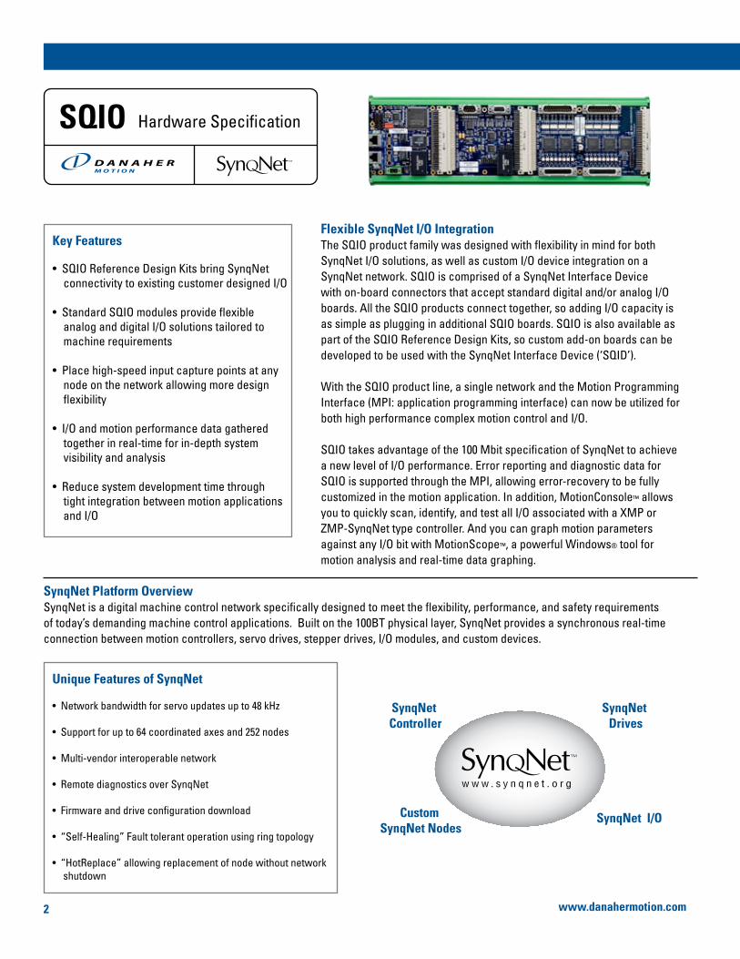
Flexible SynqNet I/O IntegrationThe SQIO product family was designed with flexibility in mind for both SynqNet I/O solutions, as well as custom I/O device integration on a SynqNet network. SQIO is comprised of a SynqNet Interface Device with on-board connectors that accept standard digital and/or analog I/O boards. All the SQIO products connect together, so adding I/O capacity is as simple as plugging in additional SQIO boards. SQIO is also available as part of the SQIO Reference Design Kits, so custom add-on boards can be developed to be used with the SynqNet Interface Device (‘SQID’).
With the SQIO product line, a single network and the Motion Programming Interface (MPI: application programming interface) can now be utilized for both high performance complex motion control and I/O.
SQIO takes advantage of the 100 Mbit specification of SynqNet to achieve a new level of I/O performance. Error reporting and diagnostic data for SQIO is supported through the MPI, allowing error-recovery to be fully customized in the motion application. In addition, MotionConsole™ allows you to quickly scan, identify, and test all I/O associated with a XMP or ZMP-SynqNet type controller. And you can graph motion parameters against any I/O bit with MotionScope™, a powerful Windows® tool for motion analysis and real-time data graphing.
SynqNet Platform OverviewSynqNet is a digital machine control network specifically designed to meet the flexibility, performance, and safety requirements of today’s demanding machine control applications. Built on the 100BT physical layer, SynqNet provides a synchronous real-time connection between motion controllers, servo drives, stepper drives, I/O modules, and custom devices.
Unique Features of SynqNet
• Network bandwidth for servo updates up to 48 kHz
• Support for up to 64 coordinated axes and 252 nodes
• Multi-vendor interoperable network
• Remote diagnostics over SynqNet
• Firmware and drive configuration download
• “Self-Healing” Fault tolerant operation using ring topology
• “HotReplace” allowing replacement of node without network shutdown
SQIO Hardware Specification
SynqNet Controller
SynqNet Drives
SynqNet I/OCustom SynqNet Nodes
www.danahermotion.com2
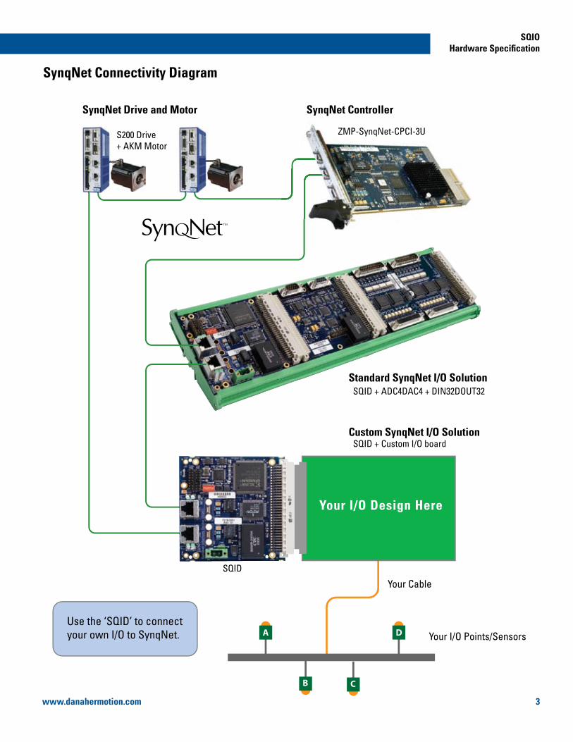
SynqNet Connectivity Diagram
ZMP-SynqNet-CPCI-3U
SQID + ADC4DAC4 + DIN32DOUT32
S200 Drive+ AKM Motor
SynqNet ControllerSynqNet Drive and Motor
Standard SynqNet I/O Solution
Custom SynqNet I/O Solution
A D
B C
SQID
SQID + Custom I/O board
Your I/O Design Here
Your Cable
Your I/O Points/SensorsUse the ‘SQID’ to connectyour own I/O to SynqNet.
SQIOHardware Specification
www.danahermotion.com 3

Overview of SQIO Board-to-Board Connectors
Digital I/O32 Inputs, 32 OutputsUp to 8 per SQID
Analog I/O4 Inputs, 4 OutputsUp to 4 per SQID16-bit addressing
SynqNet Interface Device (SQID)Standard SynqNet network interface board
SQIO HousingUse standard DIN rail mount plastic extrusions for custom mounting
Provides SynqNet network interface & power to all other I/O boards. Use a ‘SQID’ and your own custom-built I/O board to interface your own system I/O with the SynqNet network.
SynqNet Interface Device ‘SQID’ T019-0001, T019-0002,T019-0003, T019-0004
Provides 32 digital inputs and 32 digital opto-isolated outputs per board, (4) 25-pin ‘D’ digital I/O connectors, and board-to-board connectors for easy integration and future expansion. Up to 8 ‘DIN32DOUT32’ boards per SQID.
Digital I/O Device ‘DIN32DOUT32’ T020-0001
Provides 4 analog inputs and 4 analog outputs per board, 16 bit addressing, (2) 9 ‘D’ analog I/O connectors, and board-to-board connectors for easy integration and future expansion. Up to 4 boards per SQID.
Analog I/O Device ‘ADC4DAC4’ T021-0001
Provides 32 digital inputs designed for high-speed capture (probe).
High Speed Capture Device ‘HSIN32’ T024-0001
A combination of Digital and Analog I/O on one board.
Mixed Module I/O Device ‘MIXEDMODULE1’ T022-0002 Provides easy prototyping and wiring.
Connects via the ‘D’ connectors on the ‘DIN32DOUT32.’ Convenient Phoenix Combicon vertical connectors.
Digital I/O Breakout Board‘DIN32DOUT32-BO’ 8001-0042
www.danahermotion.com4

SQIO Reference Design Kits are also available for independent development of ‘exact-fit’ I/O solutions. Customize your own I/O modules and/or use a combination of existing SQIO I/O products to meet your I/O needs.
The SynqNet Reference Design Kits include:
• Reference schematics for various SynqNet nodes
• Reference Bill of Materials (BOM) w/approved vendors list
• SQID Module EEPROM specification
• SQIO Designers Manual
• Standard FPGA binary image (boot and run-time)
• Standard CPLD binary image
• Software API & Utilities for verification and debugging
• Full integration support
Example 1
Build a custom board for
use with the SQID.
Example 2
Build a custom board for
use with the SQID and
another I/O board.
SQID 256 DIGITAL I/O
Customized
16 ANALOG I/O
Customize
d
SQID 32 DIGITAL I/O
Assemble your own custom SQIO module by using a SQID interface board and any combination of SQIO I/O boards.
Here is a sample of common SQIO implementations.
NOTE: The HSIN board must be used with the appropriate SQID (T019-0004).
Standard SQIO Implementations
SQID + HSIN32
10cm x 18.9cm
SQID + ADC4DAC4
10cm x 21.8cm
SQID + DIN32DOUT32
10cm x 27.5cm
SQID + MIXEDMODULE1
10cm x 40.5cm
SQID + DIN32DOUT32 + ADC4DAC4
10cm x 40.5cm
Custom SQIO Implementations
SQIOHardware Specification
www.danahermotion.com 5

24V GND
24VGND
SynqNet ConnectorStandard RJ45
Mating ConnectorShielded RJ45Recommended
(Optional)Micro-D ConnectorMolex Inc.Mfg P/N 83611-9006
Micro-D Mating ConnectorMolex Inc.Mfg P/N 83421-9014
SynqNetIN
1 Transmit +2 Unused 1+3 Ground4 Unused 2+5 Receive +6 Transmit -7 Unused 1-8 Unused 2-9 Receive -
1 2 59
3 46 7 8
SynqNetOUT
1 Receive +2 Unused 1+3 Ground4 Unused 2+5 Transmit +6 Receive -7 Unused 1-8 Unused 2-9 Transmit -
1 2 59
3 46 7 8
SynqNetIN
1 Transmit +2 Transmit - 3 Receive +4 Unused 1+5 Unused 1-6 Receive -7 Unused 2+8 Unused 2-
1 Receive +2 Receive -3 Transmit +4 Unused 1+5 Unused 1-6 Transmit -7 Unused 2+8 Unused 2-
SynqNetOUT
Power ConnectorPhoenix Connectors Mfg P/N 17 77 07 3
Mating ConnectorPhoenix ConnectorsMfg P/N 17 77 98 9
Specifications
Dimensions Pinouts and Connector Information
100
18
7(3.94")
100
(3.9
4")
100 (3.94")
(0.7
1")
TOP VIEW
SIDE VIEW
RJ45 RJ45
ConnectorsSynqNet Connectors SQID-to-Board Connectors
RJ-45 standard or Micro-D option96-pin Type C
EnvironmentOperating TemperatureStorage TemperatureHumidity
0-50º C0-50º C20-80% RH, non-condensing
PowerInputCurrent Consumption
24 Vdc100mA @ 3.3V300mA @ 1.8V
Function SpecificationParameter
SQIO-SQIDPN: T019-0001, T019-0002, T019-0003, T019-0004
The SQID provides the necessary interface and power between I/O modules and the SynqNet network.
SynqNet Interface Device Board - ‘SQID’
T019-0001 SQI0-SQID-RAFT-RJ-VERT RJ45 vertical orientation
Part Number SynqNet ConnectorDescription
T019-0002 SQI0-SQID-RAFT-RJ-RA RJ45 right angle orientation
T019-0003 SQI0-SQID-RAFT-UD-VERT Micro D9, vertical orientation
T019-0004* SQI0-SQID-RAFT-RJ-VERT-300 RJ45, vertical orientation
* The ‘HSIN’ must be used with the T019-0004.
Part Number Table
www.danahermotion.com6

SQID + High Speed Digital Input Board (HSIN32) – 32 digital inputs designed for high-speed capture
Specifications
Dimensions Pinouts and Connector Information
Digital I/O ConnectorsStandard 25-pin ‘D’ Connectors
Connectors Digital Input ConnectorsBoard-to-Board Connectors
25-pin ‘D’ - (2F)96-pin Type R & Type C
Motor I/O
Motor ResourcesDigital InputsHigh-speed Capture RegistersCapture Latency
232 opto-isolated16 (8/motor)< 1 microsecond
EnvironmentOperating TemperatureStorage TemperatureHumidity
0-50º C0-50º C20-80% RH, non-condensing
Function SpecificationParameter
Digital Input Internal Circuit Diagram
87 (3.43")
100
(3
.94"
)
J2
J3
1 OPTO_IN1_0 2 OPTO_IN1_1 3 OPTO_IN1_2 4 OPTO_IN1_3 5 OPTO_IN1_4 6 OPTO_IN1_5 7 OPTO_IN1_6 8 OPTO_IN1_7 9 +24V (output)10 24V_RTN11 OPTO_IN1_812 OPTO_IN1_913 OPTO_IN1_10
14 OPTO_IN1_1115 OPTO_IN1_1216 OPTO_IN1_1317 OPTO_IN1_1418 OPTO_IN1_1519 +24V (output)20 24V_RTN21 NC22 NC23 NC24 NC25 NC
1
13
14
25
Digital In 1
1 OPTO_IN0_0 2 OPTO_IN0_1 3 OPTO_IN0_2 4 OPTO_IN0_3 5 OPTO_IN0_4 6 OPTO_IN0_5 7 OPTO_IN0_6 8 OPTO_IN0_7 9 +24V (output)10 24V_RTN11 OPTO_IN0_812 OPTO_IN0_913 OPTO_IN0_10
14 OPTO_IN0_1115 OPTO_IN0_1216 OPTO_IN0_1317 OPTO_IN0_1418 OPTO_IN0_1519 +24V (output)20 24V_RTN21 NC22 NC23 NC24 NC25 NC
1
13
14
25
Digital In 0
J2
J3
High Speed Capture (Probe) Support
*The HSIN32 must be connected to the (T019-0004) ‘SQID’ and cannot be attached onto another SQIO I/O board.
2k2
+24V
HSIN32
INTERNAL CIRCUIT
CUSTOMER WIRING
24V_RTN
OPTO_IN0_0
Sample Setup
ZMP-SynqNet-CPCI-3U
SQID + HSIN32
S200 Drive+ AKM Motor
Sensors
A
BPosition X
Position Y
Input A
Input B
Each input event can capture positions of multiple axes.
Position Capture/Probe
Use up to 16 simultaneous high-speed capture inputs—the perfect solution for multiple position captures for on-the-fly adjustments.
SQIO-HSIN32PN: T024-0001
SQIOHardware Specification
www.danahermotion.com 7
10n
75
10k
2k2
75
24V
+
-
10n 10k
2k2
DIN32DOUT32
INTERNAL CIRCUIT
CUSTOMER WIRING
DIN32DOUT32
INTERNAL CIRCUIT
24V
+
-
10n 10k
2k2
10n 10k
2k2
75
75
CUSTOMER WIRING
24V
+
-
LO
AD
LO
AD
DIN32DOUT32
INTERNAL CIRCUIT
CUSTOMER WIRING
B0_COM
B0_DIN_1
B0_DIN_0
B0_COM
B0_DIN_1
B0_DIN_0
B0_+24V
B0_DOUT_0
B0_24V_RTN
B0_DOUT_1
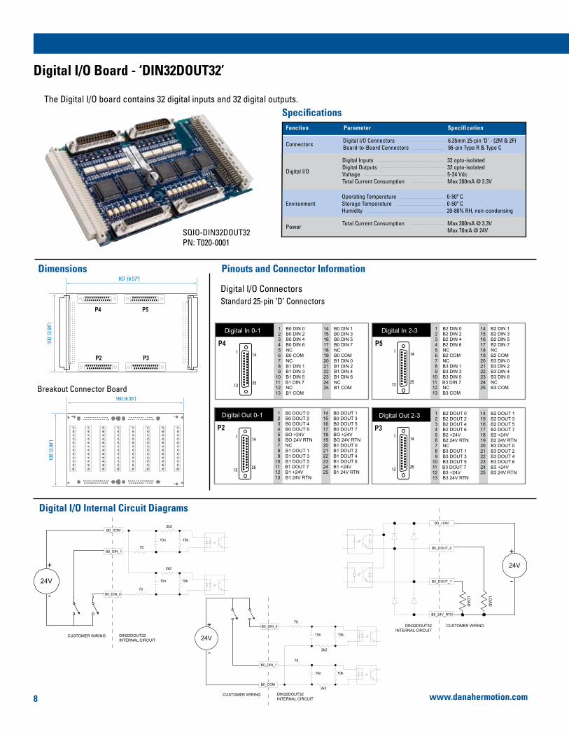
Digital I/O ConnectorsStandard 25-pin ‘D’ Connectors
Breakout Connector Board
Digital I/O Internal Circuit Diagrams
Specifications
160 (6.30")
100
(3.9
4")
Dimensions Pinouts and Connector Information
ConnectorsDigital I/O ConnectorsBoard-to-Board Connectors
6.35mm 25-pin ‘D’ - (2M & 2F)96-pin Type R & Type C
Function SpecificationParameter
Digital I/O
Digital InputsDigital OutputsVoltageTotal Current Consumption
32 opto-isolated32 opto-isolated5-24 VdcMax 200mA @ 3.3V
EnvironmentOperating TemperatureStorage TemperatureHumidity
0-50º C0-50º C20-80% RH, non-condensing
Power Total Current Consumption Max 300mA @ 3.3VMax 70mA @ 24V
167 (6.57")
100
(3.9
4")
P4 P5
P2 P3
1 B2 DIN 0 2 B2 DIN 2 3 B2 DIN 4 4 B2 DIN 6 5 NC 6 B2 COM 7 NC 8 B3 DIN 1 9 B3 DIN 310 B3 DIN 511 B3 DIN 712 NC13 B3 COM
14 B2 DIN 115 B2 DIN 316 B2 DIN 517 B2 DIN 718 NC19 B2 COM20 B3 DIN 021 B3 DIN 222 B3 DIN 423 B3 DIN 624 NC25 B3 COM
1
13
14
25
Digital In 2-3
1 B0 DOUT 0 2 B0 DOUT 2 3 B0 DOUT 4 4 B0 DOUT 6 5 BO +24V 6 BO 24V RTN 7 NC 8 B1 DOUT 1 9 B1 DOUT 310 B1 DOUT 511 B1 DOUT 712 B1 +24V13 B1 24V RTN
14 B0 DOUT 115 B0 DOUT 316 B0 DOUT 517 B0 DOUT 718 BO +24V19 BO 24V RTN20 B1 DOUT 021 B1 DOUT 222 B1 DOUT 423 B1 DOUT 624 B1 +24V25 B1 24V RTN
1
13
14
25
Digital Out 0-1 1 B2 DOUT 0 2 B2 DOUT 2 3 B2 DOUT 4 4 B2 DOUT 6 5 B2 +24V 6 B2 24V RTN 7 NC 8 B3 DOUT 1 9 B3 DOUT 310 B3 DOUT 511 B3 DOUT 712 B3 +24V13 B3 24V RTN
14 B2 DOUT 115 B2 DOUT 316 B2 DOUT 517 B2 DOUT 718 B2 +24V19 B2 24V RTN20 B3 DOUT 021 B3 DOUT 222 B3 DOUT 423 B3 DOUT 624 B3 +24V25 B3 24V RTN
1
13
14
25
Digital Out 2-3
1 B0 DIN 0 2 B0 DIN 2 3 B0 DIN 4 4 B0 DIN 6 5 NC 6 B0 COM 7 NC 8 B1 DIN 1 9 B1 DIN 310 B1 DIN 511 B1 DIN 712 NC13 B1 COM
14 B0 DIN 115 B0 DIN 316 B0 DIN 517 B0 DIN 718 NC19 B0 COM20 B1 DIN 021 B1 DIN 222 B1 DIN 423 B1 DIN 624 NC25 B1 COM
1
13
14
25
Digital In 0-1
P4 P5
P2 P3
SQIO-DIN32DOUT32PN: T020-0001
The Digital I/O board contains 32 digital inputs and 32 digital outputs.
Digital I/O Board - ‘DIN32DOUT32’
www.danahermotion.com8

Analog I/O ConnectorsStandard 9-pin ‘D’ Connectors
Specifications
Dimensions Pinouts and Connector Information
Connectors Analog I/O ConnectorsBoard-to-Board Connectors
9-pin ‘D’ - (1M & 1F)96-pin Type R & Type C
Analog I/O
Analog InputsAnalog OutputsAddressingInput Voltage & Output VoltageSlew & Settling TimeTotal Current Consumption
4416-bit addressing±10V, fully differentiated11µS106mA @ ± 15V
EnvironmentOperating TemperatureStorage TemperatureHumidity
0-50º C0-50º C20-80% RH, non-condensing
Power Total Current Consumption Max 120mA @ 3.3VMax 120mA @ 24V
Function SpecificationParameter
110 (4.33")
100
(3.9
4")
TOP
P1 P2
Analog Inputs1 AIN0+
2 AIN1+
3 AIN2+
4 AIN3+
5 reserved
6 AIN0-
7 AIN1-
8 AIN2-
9 AIN3-
1 5
6 9
Analog Outputs1 AOUT0+
2 AOUT1+
3 AOUT2+
4 AOUT3+
5 reserved
6 AOUT0-
7 AOUT1-
8 AOUT2-
9 AOUT3-
1 5
6 9
P2
P1
Analog IN0+ 100R
100R47nF
47nF
47nF
47nF
100R
100R
100R
100R
100R
100R
Analog IN0-
Analog IN1+
Analog IN1-
Analog IN2+
Analog IN2-
Analog IN3+
Analog IN3-
-15V
+15V
MAX355CWE
EN
GND
NO1A
NO1B
NO2A
NO2B
NO3A
NO3B
NO4A
NO4B
V+
V-
Ron=285ohm
Fault Protected
+5V
4.7nF
4.7nF
DAC7731
AOUT0+
AOUT0-
VOUT
IM IM
Analog Input Analog Output
4.7nF
4.7nF
4.7nF
4.7nF
4.7nF
4.7nF
SQIO-ADC4DAC4PN: T021-0001
The Analog I/O board contains 4 ADC and 4 DAC.
Analog I/O Board - ‘ADC4DAC4’
SQIOHardware Specification
www.danahermotion.com
Analog I/O Internal Circuit Diagrams
9

Digital I/O ConnectorsStandard 37-pin ‘D’ Connectors
Specifications
Analog I/O ConnectorsStandard 25-pin ‘D’ Connectors
Dimensions Pinouts and Connector Information
Connectors Analog I/O ConnectorsBoard-to-Board Connectors
9-pin ‘D’ - (1M & 1F)96-pin Type R & Type C
Analog I/O
Analog InputsAnalog OutputsAddressingInput Voltage & Output VoltageSlew & Settling TimeTotal Current Consumption
16, differential8, single ended16-bit addressing±10V, fully differentiated11µS106mA @ ± 15V
EnvironmentOperating TemperatureStorage TemperatureHumidity
0-50º C0-50º C20-80% RH, non-condensing
Digital I/O
Digital InputsDigital OutputsMax. Input VoltageTotal Current Consumption
64 opto-isolated64 opto-isolated, current sourcing28.8 VdcMax 200mA @ 3.3V
Power Total Current Consumption Max 650mA @ 3.3VMax 200mA @ 24V
Function SpecificationParameter
306 (12.05")
100
(3.9
4")
P2
P3
J3 J4J2
P4 P5
1 B2_DIN_0 2 B2_DIN_2 3 B2_DIN_4 4 B2_DIN_6 5 B3_DIN_0 6 B3_DIN_2 7 B3_DIN_4 8 B3_DIN_6 9 NC10 B0123_COM11 NC12 B0_DIN_113 B0_DIN_314 B0_DIN_515 B0_DIN_716 B1_DIN_117 B1_DIN_318 B1_DIN_519 B1_DIN_7
20 B2_DIN_121 B2_DIN_322 B2_DIN_523 B2_DIN_724 B3_DIN_125 B3_DIN_326 B3_DIN_527 B3_DIN_728 NC29 B0123_COM30 B0_DIN_031 B0_DIN_232 B0_DIN_433 B0_DIN_634 B1_DIN_035 B1_DIN_236 B1_DIN_437 B1_DIN_6
Digital In 0-31
1
19
20
37
1 B6_DIN_0 2 B6_DIN_2 3 B6_DIN_4 4 B6_DIN_6 5 B7_DIN_0 6 B7_DIN_2 7 B7_DIN_4 8 B7_DIN_6 9 NC10 B4567_COM11 NC12 B4_DIN_113 B4_DIN_314 B4_DIN_515 B4_DIN_716 B5_DIN_117 B5_DIN_318 B5_DIN_519 B5_DIN_7
20 B6_DIN_121 B6_DIN_322 B6_DIN_523 B6_DIN_724 B7_DIN_125 B7_DIN_326 B7_DIN_527 B7_DIN_728 NC29 B4567_COM30 B4_DIN_031 B4_DIN_232 B4_DIN_433 B4_DIN_634 B5_DIN_035 B5_DIN_236 B5_DIN_437 B5_DIN_6
Digital In 32-64
1
19
20
37
1 B2_DOUT_0 2 B2_DOUT_2 3 B2_DOUT_4 4 B2_DOUT_6 5 B3_DOUT_0 6 B3_DOUT_2 7 B3_DOUT_4 8 B3_DOUT_6 9 B0123_24V10 B0123_24V_RTN11 NC12 B0_DOUT_113 B0_DOUT_314 B0_DOUT_515 B0_DOUT_716 B1_DOUT_117 B1_DOUT_318 B1_DOUT_519 B1_DOUT_7
20 B2_DOUT_121 B2_DOUT_322 B2_DOUT_523 B2_DOUT_724 B3_DOUT_125 B3_DOUT_326 B3_DOUT_527 B3_DOUT_728 B0123_24V29 B0123_24V_RTN30 B0_DOUT_031 B0_DOUT_232 B0_DOUT_433 B0_DOUT_634 B1_DOUT_035 B1_DOUT_236 B1_DOUT_437 B1_DOUT_6
Digital Out 0-31
1
19
20
37
1 B6_DOUT_0 2 B6_DOUT_2 3 B6_DOUT_4 4 B6_DOUT_6 5 B7_DOUT_0 6 B7_DOUT_2 7 B7_DOUT_4 8 B7_DOUT_6 9 B4567_24V10 B4567_24V_RTN11 NC12 B4_DOUT_113 B4_DOUT_314 B4_DOUT_515 B4_DOUT_716 B5_DOUT_117 B5_DOUT_318 B5_DOUT_519 B5_DOUT_7
20 B6_DOUT_121 B6_DOUT_322 B6_DOUT_523 B6_DOUT_724 B7_DOUT_125 B7_DOUT_326 B7_DOUT_527 B7_DOUT_728 B4567_24V29 B4567_24V_RTN30 B4_DOUT_031 B4_DOUT_232 B4_DOUT_433 B4_DOUT_634 B5_DOUT_035 B5_DOUT_236 B5_DOUT_437 B5_DOUT_6
Digital Out 32-64
1
19
20
37
P4
P5
J2
J3
1
13
14
25
Analog In 8-15
1 AIN0+ 2 ANALOG_GND_2 3 AIN1- 4 AIN2+ 5 ANALOG_GND_2 6 AIN3- 7 AIN4+ 8 ANALOG_GND_2 9 AIN5-10 AIN6+11 ANALOG_GND_212 AIN7-13 ANALOG_GND_2
14 AIN0-15 AIN1+16 ANALOG_GND_217 AIN2-18 AIN3+19 ANALOG_GND_220 AIN4-21 AIN5+22 ANALOG_GND_223 AIN6-24 AIN7+25 ANALOG_GND_2
1
13
14
25
Analog In 0-7
1 AIN8+ 2 ANALOG_GND_2 3 AIN9- 4 AIN10+ 5 ANALOG_GND_2 6 AIN11- 7 AIN12+ 8 ANALOG_GND_2 9 AIN13-10 AIN14+11 ANALOG_GND_212 AIN15-13 ANALOG_GND_2
14 AIN8-15 AIN9+16 ANALOG_GND_217 AIN10-18 AIN11+19 ANALOG_GND_220 AIN12-21 AIN13+22 ANALOG_GND_223 AIN14-24 AIN15+25 ANALOG_GND_2
1
13
14
25
Analog Out 0-7 1 AOUT0+ 2 ANALOG_GND_1 3 AOUT1- 4 AOUT2+ 5 ANALOG_GND_1 6 AOUT3- 7 AOUT4+ 8 ANALOG_GND_1 9 AOUT5-10 AOUT6+11 ANALOG_GND_112 AOUT7-13 ANALOG_GND_1
14 AOUT0-15 AOUT1+16 ANALOG_GND_117 AOUT2-18 AOUT3+19 ANALOG_GND_120 AOUT4-21 AOUT5+22 ANALOG_GND_123 AOUT6-24 AOUT7+25 ANALOG_GND_1
P2
P3
J4
NOTE: The wiring diagrams for the MixedModule1 are the same as the Digital I/O and Analog I/O boards.
SQIO-MIXEDMODULE1PN: T022-0002
The Mixed Module I/O board contains 64 digital inputs, 64 digital outputs, 16 ADC, and 8 DAC.
Mixed Module I/O Board - ‘MIXEDMODULE1’
www.danahermotion.com10

Mounting InformationSQIO modules utilize standard Phoenix Contact DIN rail mount plastic extrusions.www.phoenixcon.com
Plastic Extrusion:29 52 02 0 / UM100 / Custom Length
Additional SQIO products are also available upon request.
• Board Protective Covers Protects I/O electrical circuits from direct exposure.
• Optional DIN Rail Mounting Customizable extruded mounting material that conforms to any configuration.
Mounting Information
Accessories
Used with the ‘DIN32DOUT32’ board for easy prototyping and wiring. Connects via the ‘D’ connectors. Convenient Phoenix Combicon vertical connectors.
Digital I/O Breakout Board‘DIN32DOUT32-BO’ 8001-0042
Precut SQIO Housing
1016-0300 SQID + DIN32DOUT32 Housing, Kit, SQIO, 27.15cm
Part Number DescriptionSQIO Setup
1016-0301 SQID + ADC4DAC4 Housing, Kit, SQIO, 21.45cm
1016-0305 SQID + DIN32DOUT32 + DIN32DOUT32 Housing, Kit, SQIO, 43.95cm
1016-0302 SQID + MIXEDMODULE1 Housing, Kit, SQIO, 40.35cm
1016-0303 SQID + DIN32DOUT32 + ADC4DAC4 Housing, Kit, SQIO, 38.25cm
1016-0304 SQID + ADC4DAC4 + ADC4DAC4 Housing, Kit, SQIO, 32.55cm
1016-0306 SQID + HSIN32 Housing, Kit, SQIO, 18.45cm
TOP VIEW SIDE VIEW
Custom
100(3.94")
100
Fits 35mmDIN rail
(3.94")
SQIOHardware Specification
www.danahermotion.com 11

www.danahermotion.com
Job
No.
200
704-
01 S
QIO
-Syn
qNet
I/O
Sol
utio
ns©
2007
Dan
aher
Mot
ion(
tm).
All r
ight
s re
serv
ed.
Info
rmat
ion
& s
peci
ficat
ions
sub
ject
to c
hang
e at
any
tim
e. A
ll tra
dem
arks
pro
perty
of t
heir
resp
ectiv
e ow
ners
.
United KingdomDanaher MotionChartmoor Road, Chartwell Business ParkLeighton Buzzard, BedfordshireLU7 4WG; United KingdomPhone : +44 (0)1525 243 243Fax : +44 (0)1525 243 244E-mail : [email protected]
GermanyDanaher Motion GmbHVertriebsbüro NordWacholderstr. 40-4240489 DüsseldorfGermanyPhone : +49 (0) 203 9979 214Fax : +49 (0) 203 9979 3214E-Mail : [email protected]
Danaher Motion GmbHVertriebsbüro SüdwestBrückenfeldstraße 26/1 75015 Bretten GermanyPhone : +49 (0) 7252 97390 56Fax : +49 (0) 7252 97390 55E-Mail : [email protected]
Danaher Motion GmbHVertriebsbüro SüdostKiesgräble 789129 LangenauGermanyPhone : +49 (0) 7471 62 23 23Fax : +49 (0) 7471 62 23 26E-Mail : [email protected]
FranceDanaher MotionC.P 8001812, Rue Antoine Becquerel – Z.I. Sud72026 Le Mans Cedex 2FrancePhone: +33 (0) 243 50 03 30Fax : +33 (0) 243 50 03 39E-mail : [email protected]
ItalyDanaher Motion srlLargo Brughetti20030 Bovisio MasciagoItalyPhone: +39 0362 594260Fax : +39 0362 594263E-mail : [email protected]
SwedenDanaher MotionBox 9053291 09 KristianstadSwedenPhone : +46 (0) 44-24 67 00Fax : +46 (0) 44-24 40 85E-mail : [email protected]
SwitzerlandDanaher Motion SALa Pierreire 21029 Villars-Ste-CroixSwitzerlandPhone : +41 (0) 21 631 33 33Fax : +41 (0) 21 636 05 09E-mail : [email protected]
USA, Canada and MexicoDanaher Motion203A West Rock RoadRadford, VA 24141 USAPhone : 1-540-633-3400Fax : 1-540-639-4162E-mail : [email protected]
ChinaDanaher MotionRm 2205, Scitech Tower22 Jianguomen Wai StreetBeijing, China, 100004Phone: +86 10 6515 0260Fax : +86 10 6515 0263E-mail : [email protected]
JapanDanaher Motion Japan2F, Tokyu Reit Hatchobori Bldg,2-7-1 Hatchobori Chuo-ku,Tokyo 104-0032 JapanPhone: +81-3-6222-1051Fax : +81-3-6222-1055E-mail : [email protected]
Asia PacificDanaher Motion (HK) LtdUnit A, 16 Floor, 169 Electric RoadManulife Tower, North PointHong KongPhone: +852 2503 6581Fax: +852 2571 8585E-mail: [email protected]


