PRODUCT STANDARD INDUSTRIAL TURBINES & COMPRESSORS TC 54368 COPYRIGHT AND CONFIDENTIAL The information on this document is the property of BHARAT HEAVY ELECTRICALS LIMITED. It must not be used directly or indirectly in any way detrimental to the interest of the company. TD-106 2 Rev. No.: 5 Form No. : SQUIRREL CAGE INDUCTION MOTORS IE-2 (For BFP Drive Turbine - NTPC projects) 1. SCOPE: This standard specifies the requirements of the 3-phase medium voltage squirrel cage Induction motors used for driving Centrifugal / Screw pumps of lube oil systems of Industrial Turbo sets and BFP drives. 2. TECHNICAL REQUIREMENTS: 2.1 General: The squirrel cage induction motors shall be of horizontal foot mounted (B3) type or Vertical flange mounted (V1) type construction as per enquiry suitable for bi- directional rotation. Unless otherwise specified the motors are of type IP55 enclosure (S1) be suitable for 100% humid (at 40 deg C), salty tropical conditions and highly polluted environment. 2.2 Design Standards: The motors shall conform to relevant latest amendments of National and International Codes and standards, especially the Indian Statutory Regulations. Performance : IS 325 & IS 8789 & IEC:60034 Dimensions : IS 1231 / IS 2223 Enclosure and protection : IS 4691 Tropicalizing treatment : IS 3202 Energy Efficient motors : IS 12615 / IEC:60034-30 Mothod of Cooling : IS 6362 / (Equivalent IEC:60034 std) 2.3 Design and Constructional Features: 2.3.1 Motors shall work satisfactorily for following supply conditions: Variation of supply voltage from rated voltage : 10% Variation of supply frequency from rated frequency : ± 5% Combined voltage and frequency variation : 10% 2.3.2 The Voltage level of motors shall be as follows: (unless otherwise specified) Up to 200 kW : 3 Phase 415V AC 2.3.3 Rated frequency: 50 Hz Revisions Prepared Approved Date Refer to record of revisions M.ASIM MVS RAJU 29.10.13
Transcript
PRODUCT STANDARD INDUSTRIAL TURBINES & COMPRESSORS
1. SCOPE: This standard specifies the requirements of the 3-phase medium voltage squirrel cage Induction motors used for driving Centrifugal / Screw pumps of lube oil systems of Industrial Turbo sets and BFP drives.
2. TECHNICAL REQUIREMENTS: 2.1 General:
The squirrel cage induction motors shall be of horizontal foot mounted (B3) type or Vertical flange mounted (V1) type construction as per enquiry suitable for bi-directional rotation. Unless otherwise specified the motors are of type IP55 enclosure
(S1)
be suitable for 100% humid (at 40 deg C), salty tropical conditions and highly polluted environment.
2.2 Design Standards: The motors shall conform to relevant latest amendments of National and International Codes and standards, especially the Indian Statutory Regulations.
Performance : IS 325 & IS 8789 & IEC:60034 Dimensions : IS 1231 / IS 2223 Enclosure and protection : IS 4691 Tropicalizing treatment : IS 3202 Energy Efficient motors : IS 12615 / IEC:60034-30 Mothod of Cooling : IS 6362 / (Equivalent IEC:60034 std)
2.3 Design and Constructional Features: 2.3.1 Motors shall work satisfactorily for following supply conditions:
Variation of supply voltage from rated voltage : 10% Variation of supply frequency from rated frequency : ± 5% Combined voltage and frequency variation : 10%
2.3.2 The Voltage level of motors shall be as follows: (unless otherwise specified)
Up to 200 kW : 3 Phase 415V AC 2.3.3 Rated frequency: 50 Hz
Revisions Prepared Approved Date
Refer to record of revisions M.ASIM MVS RAJU 29.10.13
PRODUCT STANDARD INDUSTRIAL TURBINES & COMPRESSORS
TC 54368
CO
PYR
IGH
T A
ND
CO
NFI
DEN
TIA
L Th
e in
form
atio
n on
this
doc
umen
t is t
he p
rope
rty o
f BH
AR
AT
HEA
VY
ELE
CTR
ICA
LS L
IMIT
ED.
It m
ust n
ot b
e us
ed d
irect
ly o
r ind
irect
ly in
any
way
det
rimen
tal t
o th
e in
tere
st o
f the
com
pany
.
TD-1
06
2
Rev
. No.
: 5
Form
No.
:
2.3.4 The ambient temperature is 50 C and an altitude not exceeding 1000 meters above mean sea level shall be taken into consideration unless otherwise specified.
2.3.5 TEMPERATURE RISE 70 C by resistance method for both thermal class 130(B) & 155(F) insulation.
2.3.6 Continuous duty LT motors up to 160 KW Output rating (at 50 C ambient temperatures), shall be Energy Efficient motors, Efficiency class of High efficiency (IE3) as per IEC: 60034-30 unless otherwise specified.
2.3.7 Winding and Insulation shall be Non-hygroscopic, oil resistant, and flame resistant. 2.3.8 Motor body shall have two earthing points on opposite sides. 2.3.9 All motors shall be so designed that maximum inrush currents and locked rotor and
pullout torque developed by them at extreme voltage and frequency variations do not endanger the motor and driven equipment.
2.3.10 The motors shall be suitable for bus transfer schemes provided on the 11kV, 3.3 kV /415V systems without any injurious effect on its life.
2.3.11 The starting time of the motor shall be less than 3 secs. 2.4 Performance: 2.4.1 Motor shall be suitable for DOL starting. 2.4.2 The motor shall be capable of start & operating satisfactorily at full load for
5 minutes without injurious heating with 75% rated voltage at motor terminal. 2.4.3 Accelerating torque at any speed with the lowest permissible starting voltage shall be
at least 10% motor full load torque. Starting torque should not be less than 120% of FLT. The pullout torque at the rated voltage shall be not less than 205% of the full load torque with no negative tolerance. Unless otherwise agreed, the pullout torque shall not exceed 300% of the rated load torque.
2.4.4 Fault capacity of the system to which motor is connected is about 45 kA RMS 1 second.
2.4.5 Noise level for all the motors shall be limited to 85dB (A) at distance of 1 m as per IS12065 (latest) /IEC60034.
2.4.6 Vibration shall be limited within the limits prescribed in IS: 12075 / IEC 60034-14. 2.4.7 The spacing between gland plate & center of terminal stud shall be as per Table-1. 2.4.8 For motors with starting time upto 20 secs. at minimum permissible voltage during
starting, the locked rotor withstand time under hot condition at highest voltage limit shall be at least 2.5 secs. more than starting time. Speed switches mounted on the motor shaft shall be provided in cases where above requirements are not met.
2.4.9 The ratio of locked rotor KVA at rated voltage to rated KW shall not exceed the following (without any further tolerance) a) Below 110 kW: 10.0 (b) From 110 kW & up to 200 kW: 9.0
2.5 ACCESSORIES:
PRODUCT STANDARD INDUSTRIAL TURBINES & COMPRESSORS
TC 54368
CO
PYR
IGH
T A
ND
CO
NFI
DEN
TIA
L Th
e in
form
atio
n on
this
doc
umen
t is t
he p
rope
rty o
f BH
AR
AT
HEA
VY
ELE
CTR
ICA
LS L
IMIT
ED.
It m
ust n
ot b
e us
ed d
irect
ly o
r ind
irect
ly in
any
way
det
rimen
tal t
o th
e in
tere
st o
f the
com
pany
.
TD-1
06
2
Rev
. No.
: 5
Form
No.
:
Terminals and Terminal box: 2.5.1 All the six terminals should be brought out on the terminal block, which shall be
provided with connecting strips and shall amply be rated. 2.5.2 The terminal box shall be capable of being turned through 360 degrees in steps of
90 degrees and location is to be midway on right hand side when viewed from coupling end.
2.5.3 The terminals shall be clearly marked R.Y.B. 2.5.4 The terminal box shall be furnished completely with nickel coated brass double
compression glands for termination. 2.5.5 Grounding pads shall be as per relevant standards.
2.6 Suitable single phase AC (240 V) space heaters shall be provided on motors rated 30KW and above to maintain windings in dry condition when motor is standstill. Space heaters shall be wired up to separate terminal box complete with removable gland plate and suitable terminals & glands for connections of cable & RTDs shall also be provided.
2.7 Lower capacity motors (less than 30kW) where separate Anti condensation heaters are not provided, two phases of the winding will be subjected to 240V AC, 50HZ supply continuously whenever the motor is switched off to avoid any ingress of moisture. The supplier in the offer in this regard shall bring out any limitations.
2.8 RATING PLATES A rating plate of non-name, Motor type, Motor model, Serial no. of motor, Rating, Voltage, Speed in RPM, Type of duty, Full load current in Amps, type of protection and efficiency class (IE2 / IE3). These rating plates shall be of White non-hygroscopic material with engraved black lettering. Stainless steel name plate as per IS 325 (Latest) /IEC 60034 (latest).
2.9 PROTECTION AND PRESERVATIVE COATING REQUIREMENTS: 2.9.1 All coated surfaces shall be protected against abrasion impact, discoloration any other
damages. All exposed threaded portions shall be suitably protected with either metallic or a nonmetallic protection device. The shaft ends of motor shall be properly sealed with suitable devices to protect them from damage The parts which are likely to get rusted due to exposure to whether, should also be properly treated and protected in a suitable manner. All primers / paints / coatings shall take into account the hot humid, corrosive & alkaline, subsoil or over ground environment as the case may be.
2.9.2 Preservative shop coating: All exposed metallic surfaces subject to corrosion shall be protected by shop application of suitable coatings. All surfaces that will not be easily accessible after the shop assembly shall be treated before hand and protected for the life of the
PRODUCT STANDARD INDUSTRIAL TURBINES & COMPRESSORS
TC 54368
CO
PYR
IGH
T A
ND
CO
NFI
DEN
TIA
L Th
e in
form
atio
n on
this
doc
umen
t is t
he p
rope
rty o
f BH
AR
AT
HEA
VY
ELE
CTR
ICA
LS L
IMIT
ED.
It m
ust n
ot b
e us
ed d
irect
ly o
r ind
irect
ly in
any
way
det
rimen
tal t
o th
e in
tere
st o
f the
com
pany
.
TD-1
06
2
Rev
. No.
: 5
Form
No.
:
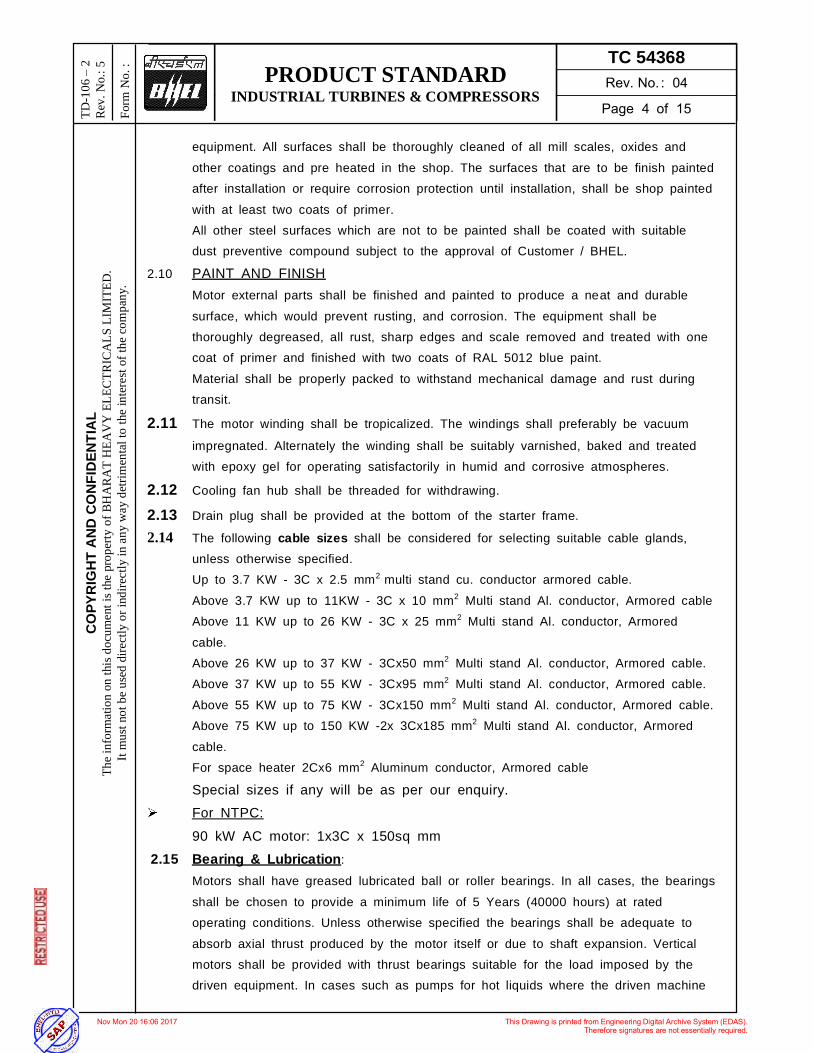
equipment. All surfaces shall be thoroughly cleaned of all mill scales, oxides and other coatings and pre heated in the shop. The surfaces that are to be finish painted after installation or require corrosion protection until installation, shall be shop painted with at least two coats of primer. All other steel surfaces which are not to be painted shall be coated with suitable dust preventive compound subject to the approval of Customer / BHEL.
2.10 PAINT AND FINISH Motor external parts shall be finished and painted to produce a neat and durable surface, which would prevent rusting, and corrosion. The equipment shall be thoroughly degreased, all rust, sharp edges and scale removed and treated with one coat of primer and finished with two coats of RAL 5012 blue paint. Material shall be properly packed to withstand mechanical damage and rust during transit.
2.11 The motor winding shall be tropicalized. The windings shall preferably be vacuum impregnated. Alternately the winding shall be suitably varnished, baked and treated with epoxy gel for operating satisfactorily in humid and corrosive atmospheres.
2.12 Cooling fan hub shall be threaded for withdrawing.
2.13 Drain plug shall be provided at the bottom of the starter frame. 2.14 The following cable sizes shall be considered for selecting suitable cable glands,
unless otherwise specified. Up to 3.7 KW - 3C x 2.5 mm2 multi stand cu. conductor armored cable.
Above 3.7 KW up to 11KW - 3C x 10 mm2 Multi stand Al. conductor, Armored cable Above 11 KW up to 26 KW - 3C x 25 mm2 Multi stand Al. conductor, Armored cable. Above 26 KW up to 37 KW - 3Cx50 mm2 Multi stand Al. conductor, Armored cable. Above 37 KW up to 55 KW - 3Cx95 mm2 Multi stand Al. conductor, Armored cable. Above 55 KW up to 75 KW - 3Cx150 mm2 Multi stand Al. conductor, Armored cable. Above 75 KW up to 150 KW -2x 3Cx185 mm2 Multi stand Al. conductor, Armored cable. For space heater 2Cx6 mm2 Aluminum conductor, Armored cable
Special sizes if any will be as per our enquiry. For NTPC:
90 kW AC motor: 1x3C x 150sq mm 2.15 Bearing & Lubrication:
Motors shall have greased lubricated ball or roller bearings. In all cases, the bearings shall be chosen to provide a minimum life of 5 Years (40000 hours) at rated operating conditions. Unless otherwise specified the bearings shall be adequate to absorb axial thrust produced by the motor itself or due to shaft expansion. Vertical motors shall be provided with thrust bearings suitable for the load imposed by the driven equipment. In cases such as pumps for hot liquids where the driven machine
PRODUCT STANDARD INDUSTRIAL TURBINES & COMPRESSORS
TC 54368
CO
PYR
IGH
T A
ND
CO
NFI
DEN
TIA
L Th
e in
form
atio
n on
this
doc
umen
t is t
he p
rope
rty o
f BH
AR
AT
HEA
VY
ELE
CTR
ICA
LS L
IMIT
ED.
It m
ust n
ot b
e us
ed d
irect
ly o
r ind
irect
ly in
any
way
det
rimen
tal t
o th
e in
tere
st o
f the
com
pany
.
TD-1
06
2
Rev
. No.
: 5
Form
No.
:
operates at high temperatures, a shaft-mounted fan shall cool bearings. This shall ensure efficient ventilation of the bearing and disperse the heat transmitted from the driven object by conduction or convection. For motors operating in hazardous areas fans shall be of an anti-static non-sparking material. Bearings shall be capable of grease injection from outside without removal of covers with motors in the running conditions. The bearing boxes shall be provided with necessary features to prevent loss of grease or entry of dust or moisture e.g. labyrinth seal. Where grease nipples are provided, these shall be associated, where necessary with appropriately located relief devices, which ensure passage of grease through the bearing. Pre-lubricated sealed bearings may be considered provided full guarantee is given for 4 to 5 years of trouble free service without the necessity of re-lubrication.
2.16 Cooling system: All motors shall be self-ventilated, fan cooled (TEFC). Fans shall be corrosion resistant or appropriately protected. They shall be suitable for motor rotation in either direction without affecting the performance of the motor. If this is not possible for large outputs, it shall be possible to reserve the fan without effecting the balancing of the motor. Motor shall be capable of 5 equal spaced cold starts per hour under normal conditions, 3 starts in quick succession from cold condition and two hot start in succession with motor initially at normal running condition.
2.17 ROTOR: The rotor shall be of squirrel cage type, dynamically balanced to provide a low vibration level and long service life of the bearings. The accepted values of peak-to-peak vibration amplitudes for a motor at rated voltage and speed on a machined surface bedplate with the motor leveled and with a half-key or coupling fitted shall not exceed those given in IS-12075 (latest).
3. TESTS CERTIFICATE: 3 copies of performance test certificate of motor shall be supplied for each item of the consignment quoting BHEL Standard number, purchase order number and
4. GUARANTEE CERTIFICATE: 4.1 A guarantee certificate for 24 months of trouble free performance from the date of
shipment or 18 months from the date of commissioning whichever is earlier shall be supplied.
4.2 If any mal-performance or defects occur during the guarantee period, the vendor shall make all necessary alteration, repairs and replacement free of charge.
5. SCOPE OF SUPPLY: 5.1 Main Supply 5.1.1 Motor with suitable cable glands and along with shaft keys.
PRODUCT STANDARD INDUSTRIAL TURBINES & COMPRESSORS
TC 54368
CO
PYR
IGH
T A
ND
CO
NFI
DEN
TIA
L Th
e in
form
atio
n on
this
doc
umen
t is t
he p
rope
rty o
f BH
AR
AT
HEA
VY
ELE
CTR
ICA
LS L
IMIT
ED.
It m
ust n
ot b
e us
ed d
irect
ly o
r ind
irect
ly in
any
way
det
rimen
tal t
o th
e in
tere
st o
f the
com
pany
.
TD-1
06
2
Rev
. No.
: 5
Form
No.
:
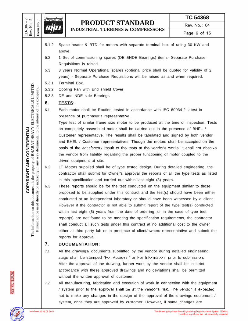
5.1.2 Space heater & RTD for motors with separate terminal box of rating 30 KW and above.
5.2 1 Set of commissioning spares (DE &NDE Bearings) items- Separate Purchase Requisitions is raised.
5.3 3 years Normal Operational spares (optional price shall be quoted for validity of 2 years) - Separate Purchase Requisitions will be raised as and when required.
5.3.1 Terminal Box. 5.3.2 Cooling Fan with End shield Cover 5.3.3 DE and NDE side Bearings
6. TESTS: 6.1 Each motor shall be Routine tested in accordance with IEC 60034-2 latest in
Type test of similar frame size motor to be produced at the time of inspection. Tests on completely assembled motor shall be carried out in the presence of BHEL / Customer representative. The results shall be tabulated and signed by both vendor and BHEL / Customer representatives. Though the motors shall be accepted on the
the vendor from liability regarding the proper functioning of motor coupled to the driven equipment at site.
6.2 LT Motors supplied shall be of type tested design. During detailed engineering, the contractor shall submit for Owner's approval the reports of all the type tests as listed in this specification and carried out within last eight (8) years.
6.3 These reports should be for the test conducted on the equipment similar to those proposed to be supplied under this contract and the test(s) should have been either conducted at an independent laboratory or should have been witnessed by a client. However if the contractor is not able to submit report of the type test(s) conducted within last eight (8) years from the date of ordering, or in the case of type test report(s) are not found to be meeting the specification requirements, the contractor shall conduct all such tests under this contract at no additional cost to the owner either at third party lab or in presence of client/owners representative and submit the reports for approval.
7. DOCUMENTATION: 7.1 All the drawings/ documents submitted by the vendor during detailed engineering
After the approval of the drawing, further work by the vendor shall be in strict accordance with these approved drawings and no deviations shall be permitted without the written approval of customer.
7.2 All manufacturing, fabrication and execution of work in connection with the equipment / system prior to not to make any changes in the design of the approval of the drawings equipment / system, once they are approved by customer. However, if some changes are
PRODUCT STANDARD INDUSTRIAL TURBINES & COMPRESSORS
TC 54368
CO
PYR
IGH
T A
ND
CO
NFI
DEN
TIA
L Th
e in
form
atio
n on
this
doc
umen
t is t
he p
rope
rty o
f BH
AR
AT
HEA
VY
ELE
CTR
ICA
LS L
IMIT
ED.
It m
ust n
ot b
e us
ed d
irect
ly o
r ind
irect
ly in
any
way
det
rimen
tal t
o th
e in
tere
st o
f the
com
pany
.
TD-1
06
2
Rev
. No.
: 5
Form
No.
:
necessitated in the design of equipment / system at a later date, the vendor may do so, but such changes shall promptly be brought to the notice of customer indicating the reasons for the change and get the revised drawing approved again in strict conformance to the provisions of the technical specification.
7.3 LIST OF TESTS FOR WHICH REPORTS HAVE TO BE SUBMITTED All the motors shall be tested in accordance of IEC 60034-2 The following type test reports shall be submitted for each type and rating of
LT motor of above 50 KW only 1. Measurement of resistance of windings of stator and wound rotor. 2. No load test at rated voltage to determine input current power and speed 3. Open circuit voltage ratio of wound rotor motors (in case of Slip ring motors) 4. Full load test to determine efficiency power factor and slip. 5. Temperature rise test. 6. Momentary excess torque test. 7. High voltage test. 8. Test for vibration severity of motor. 9. Test for noise levels of motor (Shall be limited to 85 dB (A) until otherwise
specified) 10. Test for degree of protection and 11. Over speed test. All acceptance and routine tests as per the specification and relevant standards shall be carried out. Charges for these shall be deemed to be included in the equipment price. The type test reports once approved for any projects shall be treated as reference. For subsequent projects of NTPC, an endorsement sheet will be furnished by the
shall be highlighted on the endorsement sheet. 7.4 Drawings, Data sheets, Curves for Information
copy).
prints.
O&M manual with project drawings, data sheets, performance and functional guarantee test reports.
8. DRAWINGS, DATA TO BE FURNISHED 8.1 Documents to be sent along with offer (2 copies)
(Without following data, offers will not be considered.)
8.1.1 The descriptive leaflets / catalogues giving full sectional details of the item.
PRODUCT STANDARD INDUSTRIAL TURBINES & COMPRESSORS
TC 54368
CO
PYR
IGH
T A
ND
CO
NFI
DEN
TIA
L Th
e in
form
atio
n on
this
doc
umen
t is t
he p
rope
rty o
f BH
AR
AT
HEA
VY
ELE
CTR
ICA
LS L
IMIT
ED.
It m
ust n
ot b
e us
ed d
irect
ly o
r ind
irect
ly in
any
way
det
rimen
tal t
o th
e in
tere
st o
f the
com
pany
.
TD-1
06
2
Rev
. No.
: 5
Form
No.
:
8.1.2 Motor Overall dimensional drawing. 8.1.3 Motor cross-sectional drawing showing spare part details. 8.1.4 Filled in motor data sheets. 8.1.5 Performance curve of motor. 8.1.6 Speed torque characteristic curve of motor along with GD2 Value. 8.1.7 Quality plan 8.2 DOCUMENTS TO BE SENT AFTER PLACEMENT OF ORDER FOR
APPROVAL (3 Hard Copies + 1 Soft copy) 8.2.1 Motor Overall dimensional drawing 8.2.2 Motor cross-sectional drawing showing spare part details. 8.2.3 Filled in motor data sheets. 8.2.4 Performance curve of motor 8.2.5 Speed torque characteristic curve of motor along with GD2 value. 8.2.6 Quality plan 8.2.7 Type test report
8.3 DOCUMENT TO BE SUBMITTED AFTER APPROVAL (10 Copies + 1 Soft copy) 8.3.1 Material test certificates. 8.3.2 Performance test certificates & Performance curve. 8.3.3 Guarantee certificates 8.3.4 Motor Overall dimensional drawing. 8.3.5 Filled in motor data sheets. 8.3.6 Quality plan. 8.3.7 Type test report 8.3.8 O&M Manual 9. SPECIAL NOTES: 9.1 Final documents shall be furnished in CD for using in MS word, AutoCAD & PDF. 9.2 Before forwarding the drawings and documents, vendor shall ensure that the following
information is properly entered in each drawing. 9.2.1 Name of the equipment 9.2.2 Equipment tag number 9.2.3 Name of the project 9.2.4 Client 9.2.5 Drawing / Document title 9.2.6 Drawing / Document number. 9.2.7 Revision and date. 9.2.8 The man hall be marked at suitable location. 9.2.9 A tag number bearing the relevant 12 digit material code shall be attached for each
item. 10. REFERENCE
PRODUCT STANDARD INDUSTRIAL TURBINES & COMPRESSORS
TC 54368
CO
PYR
IGH
T A
ND
CO
NFI
DEN
TIA
L Th
e in
form
atio
n on
this
doc
umen
t is t
he p
rope
rty o
f BH
AR
AT
HEA
VY
ELE
CTR
ICA
LS L
IMIT
ED.
It m
ust n
ot b
e us
ed d
irect
ly o
r ind
irect
ly in
any
way
det
rimen
tal t
o th
e in
tere
st o
f the
com
pany
.
TD-1
06
2
Rev
. No.
: 5
Form
No.
:
IS 325: THREE-PHASE INDUCTION MOTORS IS 8789: Values of performance characteristics for three-phase induction motors(up to 37 kw)
IEC:60034: Rotating electrical machines IS 1231: Dimensions of Three-phase Foot-mounted Induction Motors IS 2223: Dimensions of flange mounted ac induction motors IS 4691: Degrees of protection provided by enclosure for rotating electrical machinery IS 3202: Code of practice for climate proofing of electrical equipment IS 12615, Energy Efficient Induction Motors - Three Phase Squirrel Cage IEC:60034-30: Rotating electrical machines - Part 30: Efficiency classes of single-
speed, three-phase, cage-induction motors (IE-code) IS 6362: Designation of methods of cooling of rotating electrical machines
11. TABLE Table 1: S.N. Motor MCR in KW Minimum distance between centre of
stud and gland plate in mm 1 UP to 3 KW As per manufacturer's practice. 2 Above 3 KW - up to 7 KW 85 3 Above 7 KW - up to 13 KW 115 4 Above 13 KW - up to 24 KW 167 5 Above 24 KW - up to 37 KW 196 6 Above 37 KW - up to 55 KW 249 7 Above 55 KW - up to 90 KW 277 8 Above 90 KW - up to 125 KW 331 9 Above 125 KW-up to 200 KW 203 DIMENSIONS OF TERMINAL BOXES FOR LV MOTORS PHASE TO PHASE/ PHASE TO EARTH AIR CLEARANCE: NOTE: Minimum inter-phase and phase-earth air clearances for LT motors with lugs installed shall be as follows: S.N. Motor MCR in KW Clearance 1 UP to 110 KW 10mm 2 Above 110 KW and up to 150 KW 12.5mm
3 Above 150 KW 19mm
12. DATA SHEET (NTPC FORMAT):
DE-1 LT MOTORS A. GENERAL
PRODUCT STANDARD INDUSTRIAL TURBINES & COMPRESSORS
TC 54368
CO
PYR
IGH
T A
ND
CO
NFI
DEN
TIA
L Th
e in
form
atio
n on
this
doc
umen
t is t
he p
rope
rty o
f BH
AR
AT
HEA
VY
ELE
CTR
ICA
LS L
IMIT
ED.
It m
ust n
ot b
e us
ed d
irect
ly o
r ind
irect
ly in
any
way
det
rimen
tal t
o th
e in
tere
st o
f the
com
pany
.
TD-1
06
2
Rev
. No.
: 5
Form
No.
:
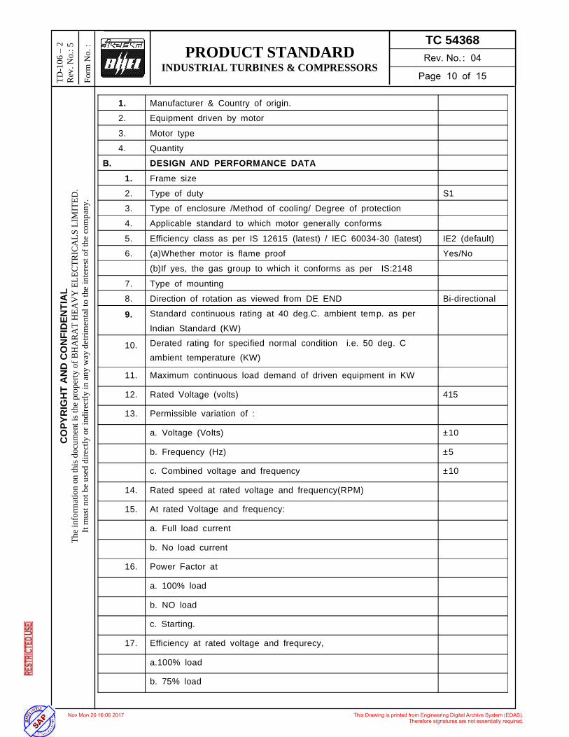
1. Manufacturer & Country of origin. 2. Equipment driven by motor 3. Motor type 4. Quantity
B. DESIGN AND PERFORMANCE DATA 1. Frame size 2. Type of duty S1 3. Type of enclosure /Method of cooling/ Degree of protection 4. Applicable standard to which motor generally conforms 5. Efficiency class as per IS 12615 (latest) / IEC 60034-30 (latest) IE2 (default) 6. (a)Whether motor is flame proof Yes/No
(b)If yes, the gas group to which it conforms as per IS:2148 7. Type of mounting 8. Direction of rotation as viewed from DE END Bi-directional 9. Standard continuous rating at 40 deg.C. ambient temp. as per
Indian Standard (KW)
10. Derated rating for specified normal condition i.e. 50 deg. C ambient temperature (KW)
11. Maximum continuous load demand of driven equipment in KW
12. Rated Voltage (volts) 415
13. Permissible variation of :
a. Voltage (Volts) ±10
b. Frequency (Hz) ±5
c. Combined voltage and frequency ±10
14. Rated speed at rated voltage and frequency(RPM)
15. At rated Voltage and frequency:
a. Full load current
b. No load current
16. Power Factor at
a. 100% load
b. NO load
c. Starting.
17. Efficiency at rated voltage and frequrecy,
a.100% load
b. 75% load
PRODUCT STANDARD INDUSTRIAL TURBINES & COMPRESSORS
TC 54368
CO
PYR
IGH
T A
ND
CO
NFI
DEN
TIA
L Th
e in
form
atio
n on
this
doc
umen
t is t
he p
rope
rty o
f BH
AR
AT
HEA
VY
ELE
CTR
ICA
LS L
IMIT
ED.
It m
ust n
ot b
e us
ed d
irect
ly o
r ind
irect
ly in
any
way
det
rimen
tal t
o th
e in
tere
st o
f the
com
pany
.
TD-1
06
2
Rev
. No.
: 5
Form
No.
:
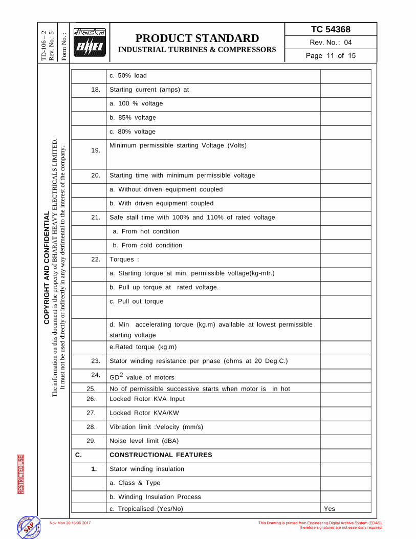
c. 50% load
18. Starting current (amps) at
a. 100 % voltage
b. 85% voltage
c. 80% voltage
19. Minimum permissible starting Voltage (Volts)
20. Starting time with minimum permissible voltage
a. Without driven equipment coupled
b. With driven equipment coupled
21. Safe stall time with 100% and 110% of rated voltage
a. From hot condition
b. From cold condition
22. Torques :
a. Starting torque at min. permissible voltage(kg-mtr.)
b. Pull up torque at rated voltage.
c. Pull out torque
d. Min accelerating torque (kg.m) available at lowest permissible starting voltage
e.Rated torque (kg.m)
23. Stator winding resistance per phase (ohms at 20 Deg.C.)
24. GD2 value of motors
25. No of permissible successive starts when motor is in hot 26. Locked Rotor KVA Input
27. Locked Rotor KVA/KW
28. Vibration limit :Velocity (mm/s)
29. Noise level limit (dBA)
C. CONSTRUCTIONAL FEATURES
1. Stator winding insulation
a. Class & Type
b. Winding Insulation Process
c. Tropicalised (Yes/No) Yes
PRODUCT STANDARD INDUSTRIAL TURBINES & COMPRESSORS
TC 54368
CO
PYR
IGH
T A
ND
CO
NFI
DEN
TIA
L Th
e in
form
atio
n on
this
doc
umen
t is t
he p
rope
rty o
f BH
AR
AT
HEA
VY
ELE
CTR
ICA
LS L
IMIT
ED.
It m
ust n
ot b
e us
ed d
irect
ly o
r ind
irect
ly in
any
way
det
rimen
tal t
o th
e in
tere
st o
f the
com
pany
.
TD-1
06
2
Rev
. No.
: 5
Form
No.
:
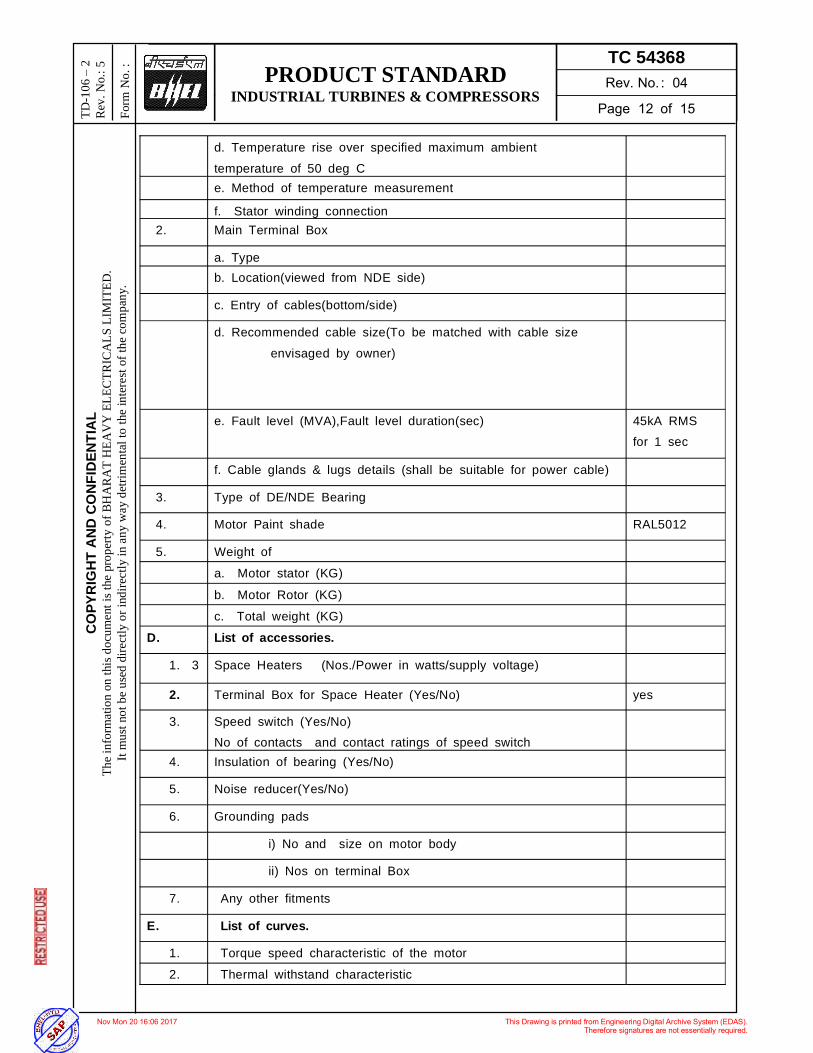
d. Temperature rise over specified maximum ambient temperature of 50 deg C
e. Method of temperature measurement
f. Stator winding connection 2. Main Terminal Box
a. Type b. Location(viewed from NDE side)
c. Entry of cables(bottom/side)
d. Recommended cable size(To be matched with cable size envisaged by owner)
e. Fault level (MVA),Fault level duration(sec) 45kA RMS for 1 sec
f. Cable glands & lugs details (shall be suitable for power cable)
3. Type of DE/NDE Bearing
4. Motor Paint shade RAL5012 (Blue)5. Weight of
a. Motor stator (KG) b. Motor Rotor (KG) c. Total weight (KG) D. List of accessories.
1. 3 Space Heaters (Nos./Power in watts/supply voltage)
2. Terminal Box for Space Heater (Yes/No) yes
3. Speed switch (Yes/No) No of contacts and contact ratings of speed switch
4. Insulation of bearing (Yes/No)
5. Noise reducer(Yes/No)
6. Grounding pads
i) No and size on motor body
ii) Nos on terminal Box
7. Any other fitments
E. List of curves.
1. Torque speed characteristic of the motor 2. Thermal withstand characteristic
PRODUCT STANDARD INDUSTRIAL TURBINES & COMPRESSORS
TC 54368
CO
PYR
IGH
T A
ND
CO
NFI
DEN
TIA
L Th
e in
form
atio
n on
this
doc
umen
t is t
he p
rope
rty o
f BH
AR
AT
HEA
VY
ELE
CTR
ICA
LS L
IMIT
ED.
It m
ust n
ot b
e us
ed d
irect
ly o
r ind
irect
ly in
any
way
det
rimen
tal t
o th
e in
tere
st o
f the
com
pany
.
TD-1
06
2
Rev
. No.
: 5
Form
No.
:
3. Starting. current Vs. Time 4. Starting. current Vs speed 5. P.F. and Effi. Vs Load
13. VARIANT TABLE:
Var. No.
Description Material code
01 TEFC SQ. CAGE HOR FOOT MOUNTED (B3) A.C IND. MOTOR FOR L.O.P. RATING: 90 KW, 415 VAC, 1450 RPM EFFICENCY AS PER IE2 IEC60034-30, SCOPE AS PER CLAUSE 5.1, NTPC Project
TC9754368015
02 SPARE SET OF BEARINGS (DE+NDE) FOR 90 KW A.C MOTOR- COMMISSIONING SPARE
TC9754368023
03 TEFC SQ. CAGE HOR FOOT MOUNTED (B3) A.C IND. MOTOR FOR J.O.P. RATING: 3.7 KW, 415 VAC, 1450 RPM
TC9754368031
04 TEFC SQ. CAGE HOR FOOT MOUNTED (B3) A.C IND. MOTOR FOR T.O.P. RATING: 1.5 KW, 415 VAC, 1450 RPM
TC9754368040
05 TEFC SQ. CAGE HOR FOOT MOUNTED (B3) A.C IND. MOTOR FOR CENTRIFUGE RATING: 2.2 KW, 415 VAC, 1450 RPM
TC9754368058
06 TEFC SQ. CAGE HOR FOOT MOUNTED (B3) A.C IND. MOTOR FOR CENTRIFUGE PUMP. RATING: 0.75 KW, 415 VAC, 1500 RPM
TC9754368066
07 TEFC SQ. CAGE HOR FOOT MOUNTED (B3) A.C IND. MOTOR FOR EXHAUST FAN. RATING: 0.37 KW, 415 VAC, 1500 RPM
TC9754368074
08 Cooling fan for 90KW,415V ,1450 RPM Motor TC9754368082
09 Space heater for 90KW,415V ,1450 RPM Motor TC9754368090 10 Terminal block for 90KW,415V ,1450 RPM Motor TC9754368104
11 Spare for 3.7 KW IE2 Motor as per table 1 TC9754368112
12 Spare for 1.5 KW IE2 Motor as per table 1 TC9754368120
13 Spare for 2.2 KW IE2 Motor as per table 1 TC9754368139
14 Spare for 0.37 KW IE2 Motor as per table 1 TC9754368147
15 Spare for 90 KW IE2 Motor as per table 2 TC9754368155
16 Spare for 90 KW IE2 Motor as per table 3 TC9754368163
PRODUCT STANDARD INDUSTRIAL TURBINES & COMPRESSORS
TC 54368
CO
PYR
IGH
T A
ND
CO
NFI
DEN
TIA
L Th
e in
form
atio
n on
this
doc
umen
t is t
he p
rope
rty o
f BH
AR
AT
HEA
VY
ELE
CTR
ICA
LS L
IMIT
ED.
It m
ust n
ot b
e us
ed d
irect
ly o
r ind
irect
ly in
any
way
det
rimen
tal t
o th
e in
tere
st o
f the
com
pany
.
TD-1
06
2
Rev
. No.
: 5
Form
No.
:
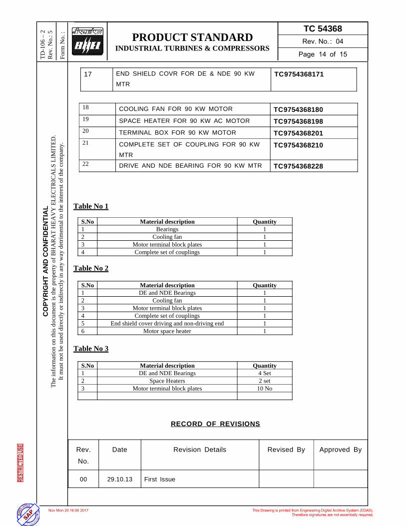
17 END SHIELD COVR FOR DE & NDE 90 KW MTR
TC9754368171
18 COOLING FAN FOR 90 KW MOTOR TC9754368180 19 SPACE HEATER FOR 90 KW AC MOTOR TC9754368198 20 TERMINAL BOX FOR 90 KW MOTOR TC9754368201 21 COMPLETE SET OF COUPLING FOR 90 KW
MTR TC9754368210
22 DRIVE AND NDE BEARING FOR 90 KW MTR TC9754368228 Table No 1
S.No Material description Quantity 1 Bearings 1 2 Cooling fan 1 3 Motor terminal block plates 1 4 Complete set of couplings 1
Table No 2
S.No Material description Quantity 1 DE and NDE Bearings 1 2 Cooling fan 1 3 Motor terminal block plates 1 4 Complete set of couplings 1 5 End shield cover driving and non-driving end 1 6 Motor space heater 1
Table No 3
S.No Material description Quantity 1 DE and NDE Bearings 4 Set 2 Space Heaters 2 set 3 Motor terminal block plates 10 No
RECORD OF REVISIONS
Rev. No.
Date Revision Details Revised By Approved By
00 29.10.13 First Issue
PRODUCT STANDARD INDUSTRIAL TURBINES & COMPRESSORS
TC 54368
CO
PYR
IGH
T A
ND
CO
NFI
DEN
TIA
L Th
e in
form
atio
n on
this
doc
umen
t is t
he p
rope
rty o
f BH
AR
AT
HEA
VY
ELE
CTR
ICA
LS L
IMIT
ED.
It m
ust n
ot b
e us
ed d
irect
ly o
r ind
irect
ly in
any
way
det
rimen
tal t
o th
e in
tere
st o
f the
com
pany
.
TD-1
06
2
Rev
. No.
: 5
Form
No.
:
01 06.01.14 Variant from 03 to 07 added Anshul M.V.S.Raju
02 22.11.14 Table 2 and variant updated till 14 Anshul M.V.S.Raju
03 07.05.15 Table 3 and variant updated till 16 Anshul M.V.S.Raju