+ All Categories
Home > Documents > SRS NFC Based Attendance System(2)

SRS NFC Based Attendance System(2)

Date post: 02-Jun-2018
Category:
Upload: charchit99
View: 266 times
Download: 0 times
Share this document with a friend
56
  A Softwar e Des ign Spe cif ication  for “NFC Based Attendance System”  in partial fulfillment   for the award of the Degree of  Bachelors of Technology  in Department of  Compute r Scie nce & En gine e r in g Submitted To: Submitted By: Mr. Mohit Khandelwal Raunak Jain Project In-charge Shashank Mudgal CS Department Sudhir Kumar IET Alwar Department of Computer Science & Engineering Institute of Engineering and Technology  Alwar October, 2014
Transcript

8/10/2019 SRS NFC Based Attendance System(2)

http://slidepdf.com/reader/full/srs-nfc-based-attendance-system2 1/56

A

Software Design Specif ication

for

“NFC Based Attendance System”

in partial fulfillment

for the award of the Degree of

Bachelors of Technology

in Department of

Computer Science & Engineer in g

Submitted To: Submitted By:

Mr. Mohit Khandelwal Raunak Jain

Project In-charge Shashank Mudgal

CS Department Sudhir Kumar

IET Alwar

Department of Computer Science & Engineering

Institute of Engineering and Technology

Alwar

October, 2014

8/10/2019 SRS NFC Based Attendance System(2)

http://slidepdf.com/reader/full/srs-nfc-based-attendance-system2 2/56

i

Candidate’s Declaration

I hereby declare that the work, which is being presented in this report, entitled “NFC

Based Attendance System ” in partial fulfillment for the award of Degree of “Bachelor

of Technology” in department of Computer Science & Engineering , Institute of

Engineering and Technology, Alwar affiliated to, Rajasthan Technical University is a

record of my own investigations carried under the Guidance of Mr. Nitin Sharma

Department of Computer Science & Engineering, IET Alwar.

I have not submitted the matter presented in this report any where for the award of any

other Degree.

Raunak Jain

Shashank Mudgal

Sudhir Kumar

Computer Science & Engineering

Counter Signed by

Mr. Nitin Sharma

Lecturer CS Dept. IET

8/10/2019 SRS NFC Based Attendance System(2)

http://slidepdf.com/reader/full/srs-nfc-based-attendance-system2 3/56

ii

Preface

Registering for attendance in education environments especially universities is a highly

demanding activity as a result of increasing number of students. The attendance process

normally involves circulating a paper for the students to register their names, or the

lecturer calling the names and registering the students either in a paper or from PDA/PC.

In the first case the student’s attention may be attracted while taking the lectures and at

the same time they can register for students who do not being present in the class. While

in the latter case the issue of cheating in the form of registering for their friends can besolved but imaging the number of students to be from 50 and above, a great portion of the

lecture time will be wasted performing this process.

In this software design specification document we propose a smart attendance system

using NFC that will simplify the attendance process, by simply touching an attendance

poster or the lectu rer’s NFC based mobile devices in the class.

This software design specification document encloses all the necessary information aboutthe NFC based attendance system. In this document all requirements of project, qualities,

dependencies, assumptions, advantages, disadvantages, UML diagrams, database table

schema has been placed.

8/10/2019 SRS NFC Based Attendance System(2)

http://slidepdf.com/reader/full/srs-nfc-based-attendance-system2 4/56

iii

Acknowledgement

It is a matter of great pleasure and privilege for us to present this software design

specification on our minor project , “NFC Based Attendance System ” that we had

developed for fulfillment of our Bachelor of Technology in Computer Science and

Engineering.

We have received enormous help, guidance and advice from many people and we feel

that it will be not be right to mention a line about at least some of them. The author would

like to express their utmost gratitude to the Institute of Engineering and Technology,

Alwar for providing opportunity to author to pursue for the degree of Bachelor of

Technology.

We are grateful to our chairman Dr. V.K. Agarwal for providing me the opportunity to

study in this institution as well as providing us with all the necessary facilities.

Our principal Dr. Anil Kumar Sharma has been source of inspiration to us in our work

sincerely. I am also thankful to Dr. Basant Kumar Verma (H.O.D., CSE) and Mr.

Mohit Khandelwal (Project In-charge) for their encouragement and guidance. Their

words of encouragement led us to finish our work successfully.

I am also thankful to my project guide Mr. Nitin Sharma and also to all faculty

members of Computer Science & Engineering and Information Technology Department

and all other for help given to us directly or indirectly for the success of this project.

Raunak Jain Roll No. – 11EIACS085

Shashank Mudgal Roll No. – 11EIACS097

Sudhir Kumar Roll No. – 11EIACS105

8/10/2019 SRS NFC Based Attendance System(2)

http://slidepdf.com/reader/full/srs-nfc-based-attendance-system2 5/56

iv

Table of ContentsCandidate’s Declaration ................................................................................................................ iPreface ............................................................................................................................................ ii

Acknowledgement ........................................................................................................................ iiiTable of Contents ......................................................................................................................... ivTable Of Figures ............................................................................................................................vList of Tables ................................................................................................................................ vi1. Introduction ..............................................................................................................................1

1.1 Background Study ......................................................................................................................... 11.2 Project Scope ................................................................................................................................ 2

2. Overall Description ....................................................................................................... ...........42.1 Product Perspective ....................................................................................................................... 42.2 Product Features............................................................................................................................ 62.3 User Classes and Characteristics................................................................................................... 62.4 Operating Environment ................................................................................................................. 72.5 Design and Implementation Constraints ....................................................................................... 82.6 Assumptions and Dependencies.................................................................................................... 8

3. External Interface Requirements .........................................................................................103.1 User Interfaces ............................................................................................................................ 103.2 Hardware Interfaces .................................................................................................................... 113.3 Software Interfaces ..................................................................................................................... 133.4 Communications Interfaces ........................................................................................................ 14

4. Other Nonfunctional Requirements .....................................................................................164.1 Safety Requirements ................................................................................................................... 164.2 Security Requirements ................................................................................................................ 164.3 Software Quality Attributes ........................................................................................................ 184.4 Assumptions ................................................................................................................................ 204.5 Constraints .................................................................................................................................. 204.6 System Environment ................................................................................................................... 204.7 Design Methodology ................................................................................................................... 214.8 Risk and Volatile areas ............................................................................................................... 23

5. Architecture ............................................................................................................................255.1 Overview ..................................................................................................................................... 255.2 Modules ...................................................................................................................................... 26

6. UML diagrams .......................................................................................................................286.1 Requirement Paragraph ............................................................................................................... 286.2 Noun Phrase Analysis ................................................................................................................. 286.3 Use Case Diagram ....................................................................................................................... 306.4 Sequence Diagram ...................................................................................................................... 316.5 Data Flow Diagram ..................................................................................................................... 336.6 Activity Diagram ........................................................................................................................ 356.7 Collaboration Diagram ................................................................................................................ 386.8 Class Diagram ............................................................................................................................. 386.9 Class-responsibility-collaboration card ....................................................................................... 396.10 E-R Diagram ............................................................................................................................... 42

7. Database Schema ...................................................................................................................437.1 Tables, Fields and Relationships ................................................................................................. 43

8. Cost Estimation ......................................................................................................................469. Appendix A: Glossary............................................................................................................4810. Appendix B: References ........................................................................................................49

8/10/2019 SRS NFC Based Attendance System(2)

http://slidepdf.com/reader/full/srs-nfc-based-attendance-system2 6/56

v

Table Of FiguresFigure 1. A proposed system of attendance ........................................................................ 1

Figure 2. Antenna circuit and its equivalent ..................................................................... 12

Figure 3. A full NFC/RFID system at 13.56 MHZ ........................................................... 13

Figure 4. NFC relay attack in peer-to-peer mode ............................................................. 17

Figure 5. NFC relay attack in reader/writer mode ............................................................ 17

Figure 6. A pictorial summary of our system ................................................................. 22

Figure 7. Overview of the automated attendance system ................................................. 23

Figure 8. Flow schema of the system................................................................................ 26

Figure 9. Use case diagram of system .............................................................................. 30

Figure 10. Sequence Diagram ........................................................................................... 32 Figure 11. 0 Level DFD .................................................................................................... 33

Figure 12. 1 Level DFD .................................................................................................... 34

Figure 13. Activity diagram for updation of student record ............................................. 35

Figure 14. Activity diagram for attendance status ............................................................ 36

Figure 15. Activity diagram for Record attendance .......................................................... 37

Figure 16. Collaboration diagram ..................................................................................... 38

Figure 17. Class Diagram ................................................................................................. 39

Figure 18. CRC for Admin ............................................................................................... 40

Figure 19. CRC for student ............................................................................................... 41

Figure 20. CRC for nfc_scanner ....................................................................................... 41

Figure 21. E-R Diagram .................................................................................................... 42

8/10/2019 SRS NFC Based Attendance System(2)

http://slidepdf.com/reader/full/srs-nfc-based-attendance-system2 7/56

vi

List of Tables

1. Table 1. Hardware Requirements ………………………………………………..07

2. Table 2. Software Requirements …………………………………………………07

3. Table 3. Admin Table …………………………………………………………....40

4. Table 4. Parent Table …………………………………………………………….41

5. Table 5. Relation Table …………………………………………………………..41

6. Table 6. Attendance Table……………………………………………………….42

7. Table 7. Student Table…………………………………………………………...42

8. Table 8. Values of variables in COCOMO Model………………………………43

9. Table 9. Acquisition Phase Distribution…………………………………………44

10. Table 10. Software Effort Distribution…………………………………………..44

8/10/2019 SRS NFC Based Attendance System(2)

http://slidepdf.com/reader/full/srs-nfc-based-attendance-system2 8/56

1

1. Introduction

1.1 Background Study

As we have seen in our schooling days that in the class when teacher comes he has totake the attendance of students by using pen and paper method, which was a very lengthyand time consuming approach. In today’s era this is very necessary to save time from allother works besides study and to employ that time in studying. So for this we also have totake care of attendance system which takes much time and to make such system in whichemployed time is very less. By making a system of attendance teacher can give hismaximum time to students. To overcome the disadvantages of this attendance system weare proposing the NFC based attendance system for schools, colleges and universities.

In the proposed system implementing a very simple NFC (Near Field Communication)System with an android application device to track the attendance details of the studentand providing some access permissions to the student in the campus. The systemimplemented in NFC was highly secured. Although the higher-layer cryptographic

protocols (e.g., SSL) are used to establish a secure channel in order to overcome GeneralSecurity Threats like Eavesdropping, Data modification, Relay attack, and Lost propertyand Walk-off.

Figure 1. A proposed system of attendance

8/10/2019 SRS NFC Based Attendance System(2)

http://slidepdf.com/reader/full/srs-nfc-based-attendance-system2 9/56

2

Although NFC based applications run in a similar manner to Bluetooth on mobile

devices, the working principal behind Near Field Communication is based on RFID.

Therefore it is essential to study the basics of RFID before discussing the technical details

of Near Field Communication. As mentioned earlier, RFID system contains 3 essential

parts which are the reader, tag, and middleware. We will briefly describe how these

components work in sync.

The RFID reader is also called an interrogator or an initiator. It is a device that

continuously propagates Radio Frequency (RF) signals and waits for a tag to response.

Readers can be stationary (fixed RFID) or moving (mobile RFID). Tags, also called

transponders, are just basically a microchip with an antenna. They come in three

varieties: Passive tags that do not contain a battery, Active tags that have a battery and

are constantly broadcasting a signal (just like the reader), and Battery Assisted Passive

(BAP) tags where the battery is activated only in presence of an RF field.

The tags can be stored in any small device or object according to their applications easily

due to their small size. A good example is tags stores on rental cars or criminals for

tracking purposes. They can also be placed in animal collars or in garments in a clothes

shop for inventory purposes. A reader can be programmed to accept information onlyfrom particular tags. For example, in faculty parking spaces on a university campus, only

the faculty is allowed to pass through whereas student cards are rejected. This depends on

the frequency, modulation, encryption, etc. and this decision is made by a form of

middleware installed on the reader.

1.2 Project Scope

This attendance system is based on very innovative technique of NFC and offers very

easy way to register day-to-day attendance in any school, college and institution. This

system saves the time, of teachers or lecturers, which is employed in manual pen and

paper system and gives accurate information about attendance of any class or student.

8/10/2019 SRS NFC Based Attendance System(2)

http://slidepdf.com/reader/full/srs-nfc-based-attendance-system2 10/56

3

This system has a very wide scope in future as this is very effective system for making

day to day attendances in schools, colleges, universities. As this system has a power of

providing instant information to parents also so it has a very good scope. It is low cost

and effective so this can also be applied in companies for employee attendances. In future

it can also be made for various cross platforms like Windows, Linux, MacOS etc.

8/10/2019 SRS NFC Based Attendance System(2)

http://slidepdf.com/reader/full/srs-nfc-based-attendance-system2 11/56

4

2. Overall Description

2.1 Product Perspective

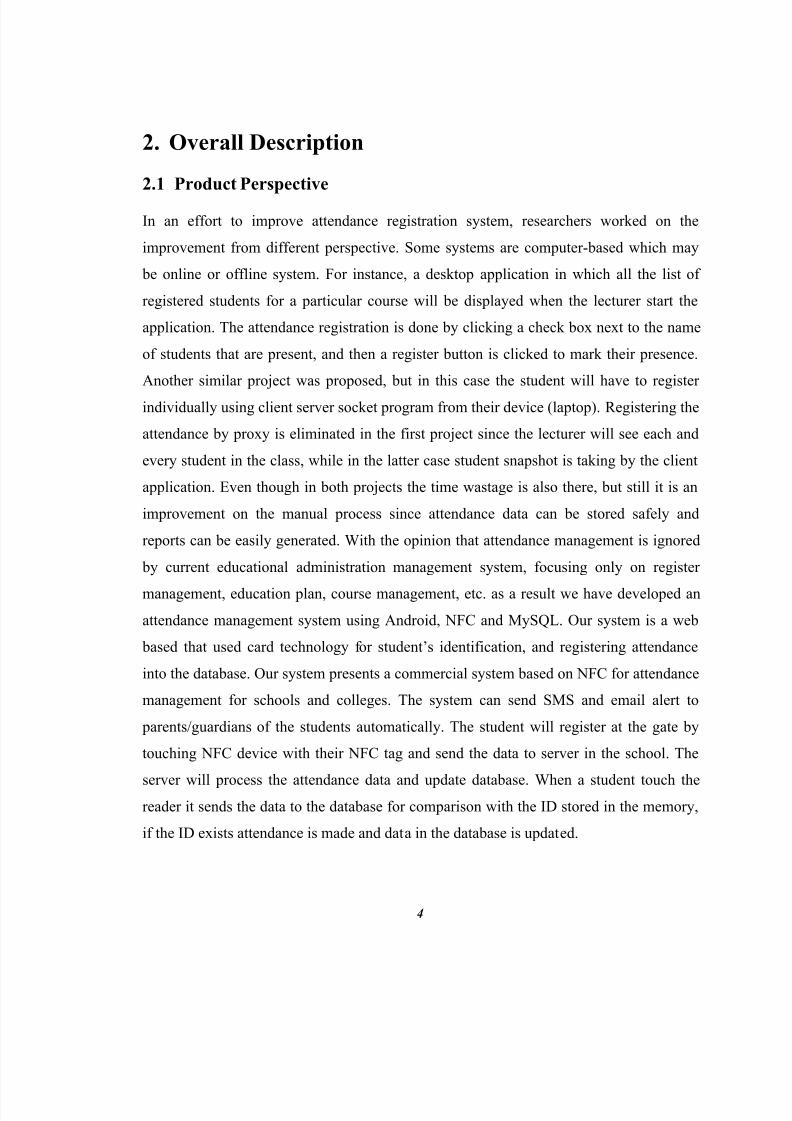
In an effort to improve attendance registration system, researchers worked on the

improvement from different perspective. Some systems are computer-based which may

be online or offline system. For instance, a desktop application in which all the list of

registered students for a particular course will be displayed when the lecturer start the

application. The attendance registration is done by clicking a check box next to the name

of students that are present, and then a register button is clicked to mark their presence.

Another similar project was proposed, but in this case the student will have to register

individually using client server socket program from their device (laptop). Registering the

attendance by proxy is eliminated in the first project since the lecturer will see each and

every student in the class, while in the latter case student snapshot is taking by the client

application. Even though in both projects the time wastage is also there, but still it is an

improvement on the manual process since attendance data can be stored safely and

reports can be easily generated. With the opinion that attendance management is ignored

by current educational administration management system, focusing only on register

management, education plan, course management, etc. as a result we have developed an

attendance management system using Android, NFC and MySQL. Our system is a web

based that used card technology f or student’ s identification, and registering attendance

into the database. Our system presents a commercial system based on NFC for attendance

management for schools and colleges. The system can send SMS and email alert to

parents/guardians of the students automatically. The student will register at the gate by

touching NFC device with their NFC tag and send the data to server in the school. The

server will process the attendance data and update database. When a student touch thereader it sends the data to the database for comparison with the ID stored in the memory,

if the ID exists attendance is made and data in the database is updated.

8/10/2019 SRS NFC Based Attendance System(2)

http://slidepdf.com/reader/full/srs-nfc-based-attendance-system2 12/56

5

The NFC-based applications simplify various human day-to-day activities by simply

touching an object fixed or integrated with NFC tag. For instance, Smart Touch is one of

the early NFC projects that focuses on NFC technology which was coordinated by VTT

Technical Research Centre Finland; applications in various areas were developed under

this project such as mobile payment and ticketing, smart poster, attendance system for

schools, home use, household access control and security, blood glucose meter, etc.

Another NFC project is attendance supervision for college and school. This service will

allow lecturers, administrators and parents to instantly know the attendance status of their

children. This attendance system is aim at providing parents real-time information about

their children’ s arrival and departure. This project has two goals: creating a ubiquitous

computing system where relation between people, practice, and technology happen as a part of a natural interaction paradigm, and to deliver applications that replace some of the

tasks that cause the teachers, students, and other staff to spend time daily. The hardware

used in the project includes NFC-based active devices (Nokia 6212 and Samsung Nexus

S), NFC-enabled passive devices (Topaz, Touchatag, and Nokia), NFC readers (ACS-

ACR-122U), and NFC Server Hosts linked to the university network which handle the

communication with the readers. This host runs the software applications that provide

access to the reader. In the attendance system each room has NFC reader which is

connected to university’ s network. Contactless technology especially NFC can be utilized

to make university life easier. Therefore, Budapest University of Technology and

Economics (BME) introduced NFC-based student attendance monitoring system. The

system can be used to track attendance percentage, in order to put the university’ s rule

concerning writing exam without a certain attendance percentage into practice. Similarly,

a mobile phone attendance system for small office employees was presented. The

employee will touch the NFC-enabled mobile device with their card, and then the

employee data (ID, Photo, Time in/Time out, and Date) will be sent to the backend

system. Therefore, we are proposing an easy to use web based attendance registration

system that will require no device other than NFC-enabled device like mobile-phone.

8/10/2019 SRS NFC Based Attendance System(2)

http://slidepdf.com/reader/full/srs-nfc-based-attendance-system2 13/56

6

2.2 Product Features

RFID Based Attendance Technology: - This attendance system uses Radio

Frequency Identification (RFID) technique, which is a wireless non-contacttechnique, which uses radio frequency electromagnetic field to transfer data, for

the purpose of automatically identifying and tracking tags attached to objects.

NFC Based System: - This system is based on Near Field Communication

system which is a set of standards for smartphones and similar devices to

establish radio communication with each other by touching them together or

bringing them into proximity, usually no more than a few centimeters. NFC is

based on Radio frequency Identification (RFID) technique.

Tracking System: - To ensure the correctness of attendances this system has a

complementary tool “Attendance Status Tracker” which gives the instant status

of attendance and teacher can cross check that all attendances which have

registered on the day are correct. This complementary tool can also be used by

student and their parents to check attendance status of student.

Smart Id: - This software requires a smart id i.e. NFC Tag, NFC Smart Card to

register one’s attendance.

2.3 User Classes and Characteristics

Admin : - College/University management is the super most user of this system.

The authorized person from the management can edit the details of any student

related to his name, id, parents etc.

8/10/2019 SRS NFC Based Attendance System(2)

http://slidepdf.com/reader/full/srs-nfc-based-attendance-system2 14/56

7

Teacher : - Teacher is that user of this system who can delete the attendance of

any student if it is fake only on that day on which it has been made. Teacher can

also check the attendance status of whole class or a particular student.

Student : - Student is the low level user who has to register his day to day

attendance by simply touching his NFC tag to the NFC scanner. Student cannot

interact with the scanner any more. To check his attendance status and attendance

percentage he has to use the different application Attendance Status Tracker

provided with his username and password.

Parent: - Parents of the students can also use the supplementary application

Attendance Status Tracker to check the attendance status of their children

remotely from anywhere.

2.4 Operating Environment

Hardware Requirements: -

Hardware Reason NFC Android Phone/Android NFC Scanner To scan id and register one’s attendance

NFC Tag/NFC Smart Card Smart ID related to only one & required to

make attendance

Table 1. Hardware Requirements

Software Requirement: -

Software Version Reason

Android OS 16(JellyBean) Minimum required version

IntelliJ Idea IDE 13.0.2 To code for project

ArgoUML .34 To make UML diagrams

Table 2. Software Requirements

8/10/2019 SRS NFC Based Attendance System(2)

http://slidepdf.com/reader/full/srs-nfc-based-attendance-system2 15/56

8

Server Side:

Web Server: Apache 2

Database server: MySQL

Operating System: Linux

Version: Ubuntu 12.04

Processor: Dual Core 1.6 GHz.

1GB RAM

Client Side:

A reliable Internet connection

Operating System: Android 4.1 and above

2.5 Design and Implementation Constraints

This system is designed for Android based NFC devices.

In this system the major constraint is that it is very necessary that the NFC-

Scanner must be an android device. Device must be connected to the internet so

that database can be updated after every attendance.

The second constraint of this system that every student must have an NFC tag to

register his attendance.

2.6 Assumptions and DependenciesIn the development of this system assumption which have been made primarily is that

when a student register his attendance he has only his NFC tag. He is not making fake

attendance of any other student just by showing his tag also.

8/10/2019 SRS NFC Based Attendance System(2)

http://slidepdf.com/reader/full/srs-nfc-based-attendance-system2 16/56

9

Another assumption that has been made is that the student is making attendance from

inside the class means he is attending the class.

We can say that this system is dependent on an operator who is watching students whilemaking attendances through their NFC tags that attendances which is being made is true.

8/10/2019 SRS NFC Based Attendance System(2)

http://slidepdf.com/reader/full/srs-nfc-based-attendance-system2 17/56

8/10/2019 SRS NFC Based Attendance System(2)

http://slidepdf.com/reader/full/srs-nfc-based-attendance-system2 18/56

11

Record Attendance: - This interface is the main interface of the system in which

a student can register his attendance by simply touching his NFC tag with the

system. In the beginning of day admin login and open this interface after that a

student can make his attendance.

Add/Delete tags: - This is the interface in which admin can delete and add a new

NFC tag. This option is available only for management.

Attendance status Class/Student: - In this interface admin can check the

attendance status of whole class as well as particular student that who is present

and not on any day.

This interface is also available in Attendance Status Tracker application for

parents, students and teachers. Student and parent can only check their

attendances while teacher can also check the attendances of whole class.

3.2 Hardware Interfaces

NFC tags are designed just like an RFID tag to be used at 13.56 MHz and therefore the

tag design is similar. At this frequency range, RFID tags mostly use the theory of

Strongly Coupled Magnetic Resonance. This is basically where two nearby loop antennae

provide strong electromagnetic mutual induction resonance. This effect is also known as

inductive coupling. During operation, other communication frequencies are disabled

which allows very fast communication between coupled resonances. Please note that this

phenomenon is valid only for loop antennae that are placed very near to each other.

In this type of system, the antennae can be represented by inductors where for a passive

device the energy is provided by the magnetic field of the reader. From EM and

transformers, we know that two coupled coils can be replaced by an equivalent

8/10/2019 SRS NFC Based Attendance System(2)

http://slidepdf.com/reader/full/srs-nfc-based-attendance-system2 19/56

12

transformer circuit as shown in Figure 2. This circuit and the whole electronic system in

Figure 3 can be analyzed to design the parameters which will provide coupled resonance

at 13.56 Mhz.

Figure 2. Antenna circuit and its equivalent

8/10/2019 SRS NFC Based Attendance System(2)

http://slidepdf.com/reader/full/srs-nfc-based-attendance-system2 20/56

13

Figure 3. A full NFC/RFID system at 13.56 MHZ

3.3 Software Interfaces

In this project following software has been used during the development:-

1. AndroidOS: - This system is basically has been developed for android devices

because now a days android phone is easily available to everyone. For this project

we have taken Android version 4.2 JellyBean APK version 16 as minimum

required version.

2. IntelliJIdea IDE: - In this project we have used IntelliJIdea Integrated

Development Environment to code the project.

3. ArgoUML: - To make UML diagrams we have used ArgoUML tool.

8/10/2019 SRS NFC Based Attendance System(2)

http://slidepdf.com/reader/full/srs-nfc-based-attendance-system2 21/56

14

4. EDraw: - This software has been used in our project to make E-R diagram and

Data Flow Diagrams.

5. Database: - We have used MySQL as database for our project to store all recordsrelated to student informations, attendance records, tags records, user records like

username, passwords etc.

6. WebServer: - To store database online we have used Apache 2 WebServer.

Whenever a student makes an attendance, to make his record update instantly, we

have stored our database on the Web Server.

7. PHP: - Preprocessor HyperText Programming language has been used in this project as a middleware between android NFC scanner and Server. Whenever a

request is generated from the system it is transferred to webserver to get response.

But actually request firstly goes to PHP page then to the server. In the same

manner response is received from WebServer.

3.4 Communications Interfaces

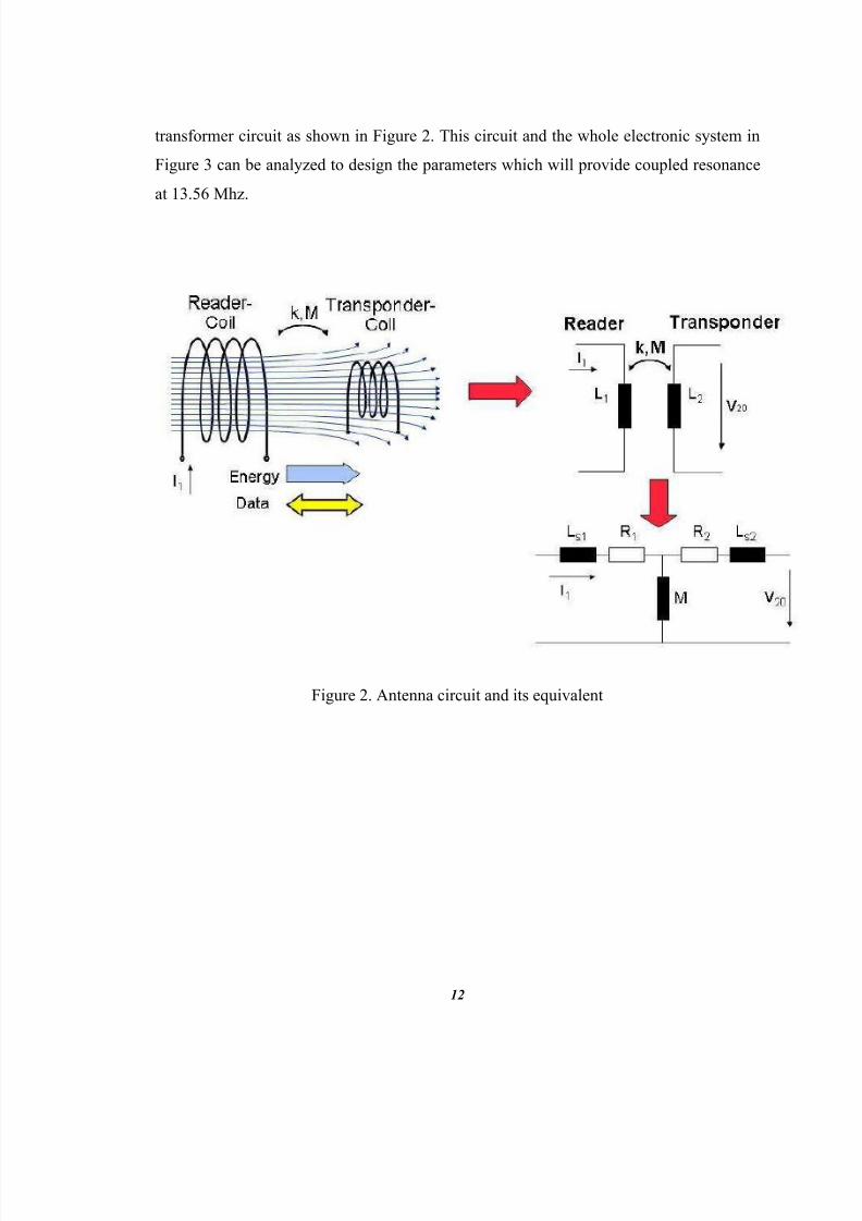
NFC can be considered a special case of RFID. It operates at a frequency of 13.56 MHz,which is one of the unlicensed frequencies. Unlicensed frequencies are commonly used in

medical application or industrial applications concerned with personal devices such as

Bluetooth, wireless devices and micro-wave ovens (2.45 GHz). The allocated Bandwidth

in the 13.56 MHz band is 14 kHz so the communication has to be in the range 13.553 –

13.567 MHz. However, in NFC the envelope of the spectrum may spread up to 1.8 MHz

using ASK modulation.

In NFC, there are two communication modes and three supported data rates andcoding/modulation schemes used. In passive mode, the initiator sends an RF signal and

the target device uses the power generated by the propagated EM field. On the other

hand, in active mode, both devices have their own power supply and use it to alternately

8/10/2019 SRS NFC Based Attendance System(2)

http://slidepdf.com/reader/full/srs-nfc-based-attendance-system2 22/56

15

generate their own RF field for communication. The three supported data rates are 106,

212 and 424 Kbit/s (maximum) which is much lower to the Bluetooth V2.1 data rate of

2.1 Mbit/s. Almost all configurations use Manchester with 10% ASK except for active

devices operating at 106 Kbit/s.

8/10/2019 SRS NFC Based Attendance System(2)

http://slidepdf.com/reader/full/srs-nfc-based-attendance-system2 23/56

16

4. Other Nonfunctional Requirements

4.1 Safety Requirements

This attendance system is based on NFC technology so this is safe in all the ways but

loop hole are found everywhere. In this attendance system the main safety requirement is

that we have to look after that a student make only his attendance. He does not make the

fake attendance of his friend by touching his tag when his friend is not present.

The other safety requirement is that student have to care his NFC tag so that the tag does

not get corrupted.

4.2 Security Requirements

Security Threats Relevant to NFC

1. Denial of Service: In NFC, a DoS attack is possible because when an NFC reader and

a tag are close enough, the reader will start reading the tag even if the tag is empty. This

is because the tag is passive and harvests energy from the signal from the reader. Thus,

the reader must continuously poll for tags to detect if there is a tag available in its range.

This means that the NFC reader could be occupied or kept busy by putting an NFC tag

within the reader's proximity. To avoid this, most mobile phones automatically turn off

their NFC read and write functionality when the screen is off.

2. NFC relay attack: It has been suggested that NFC systems are particularly vulnerable

to relay attacks. Francis presented a practical relay attack on NFC peer-to-peer mode

using Near Field Communication Interface and Protocol (NFCIP) between two NFC

enabled mobile phones. The setup of this relay attack is shown in Figure. Specially, two proxy NFC phones that are 100 meters away from each other establish a Bluetooth

connection to forward messages from the initiator device to the target device. One of the

8/10/2019 SRS NFC Based Attendance System(2)

http://slidepdf.com/reader/full/srs-nfc-based-attendance-system2 24/56

17

proxy phones presents itself as the target phone to the initiator while the other one

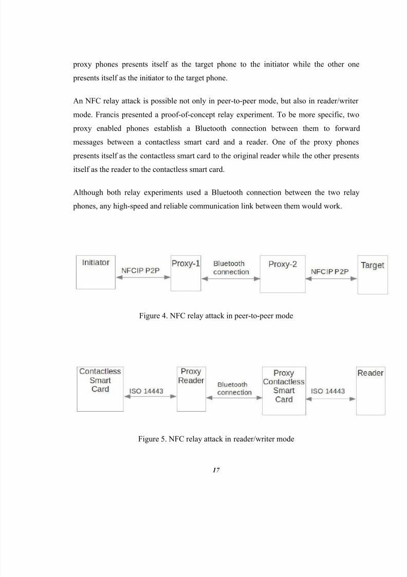
presents itself as the initiator to the target phone.

An NFC relay attack is possible not only in peer-to-peer mode, but also in reader/writermode. Francis presented a proof-of-concept relay experiment. To be more specific, two

proxy enabled phones establish a Bluetooth connection between them to forward

messages between a contactless smart card and a reader. One of the proxy phones

presents itself as the contactless smart card to the original reader while the other presents

itself as the reader to the contactless smart card.

Although both relay experiments used a Bluetooth connection between the two relay

phones, any high-speed and reliable communication link between them would work.

Figure 4. NFC relay attack in peer-to-peer mode

Figure 5. NFC relay attack in reader/writer mode

8/10/2019 SRS NFC Based Attendance System(2)

http://slidepdf.com/reader/full/srs-nfc-based-attendance-system2 25/56

8/10/2019 SRS NFC Based Attendance System(2)

http://slidepdf.com/reader/full/srs-nfc-based-attendance-system2 26/56

19

Availability: As the system is low cost and in today’s time android is such

operating system which is easily available. So this system is also easily availablefor those who want to adapt this system.

Correctness: Since this attendance system is based on NFC technology and to

make attendances it is very necessary to touch one’s NFC Tag or NFC Mobile. So

we can say that this system is very correct as compared to other attendance

systems because everyone has an unique id.

Flexibility: As the NFC technology is a part of most of the mobile operatingsystems so this system can be made for different operating systems. So it can be

said that it is flexible.

Maintainability: This system requires very less maintenance. In this system

operations can be done using NFC enabled android mobile phones/tablets so there

is no requirement of too much maintenance.

Reliability: This attendance system is reliable because it gives the correct

information about attendances of anyone and as everyone has a unique id so there

is no worry of fake proxy.

Reusability: In this system a student is given with a NFC tag and when he leaves

the schools permanently at that time that NFC tag can be allocated for a new

student who take admission in the institution. So we can say that it is reusable.

8/10/2019 SRS NFC Based Attendance System(2)

http://slidepdf.com/reader/full/srs-nfc-based-attendance-system2 27/56

20

4.4 Assumptions

In the development of this system assumption which have been made primarily is that

when a student register his attendance he has only his NFC tag. He is not making fakeattendance of any other student just by showing his tag also.

Another assumption that has been made is that the student is making attendance from

inside the class means he is attending the class.

We can say that this system is dependent on an operator who is watching students while

making attendances through their NFC tags that attendances which is being made is true.

4.5 Constraints

This system is designed for Android based NFC devices.

In this system the major constraint is that it is very necessary that the NFC-

Scanner must be an android device. Device must be connected to the internet so

that database can be updated after every attendance.

The second constraint of this system that every student must have an NFC tag toregister his attendance.

4.6 System Environment

For this project the system required is an android based NFC scanner and an NFC tag or

NFC Mobile. Scanner will scan the tag and attendance will be recorded.

8/10/2019 SRS NFC Based Attendance System(2)

http://slidepdf.com/reader/full/srs-nfc-based-attendance-system2 28/56

21

4.7 Design Methodology

The student/faculty/staff members will be equipped with a NFC enabled smart-phone.

The mobile application development will be done using the Google Android platform.Google is a major backer of Near Field Communication technology and as such has

provided many flexible APIs (Application Programming Interface) which will aid us in

this. Google provides an Android Software Development Kit which combined with the

popular Java based eclipse IDE (Integrated Development Environment) and the Android

Development Tool (ADT) plugin will help us greatly in the development of the software.

Another web-based system will also have to be developed to oversee and monitor this

system. This would be the system used by the administrators and instructors to check

student activities etc. Students would also be given access to this system so they can

check their semester progress or check their e-Wallet balances.

As we mentioned in the objective, this proposed NFC system would assist in automated

attendance, as an identification and security clearance device and as an e-wallet. Now we

will tackle each of these areas separately.

The key to the academic success of a university is punctuality of the classes. The taking

of the attendance wastes around 5-10 minutes of important teaching time. This proposed

system has the potential to replace all the manual attendances still taken in classes and

eliminate this waste.

8/10/2019 SRS NFC Based Attendance System(2)

http://slidepdf.com/reader/full/srs-nfc-based-attendance-system2 29/56

22

Figure 6. A pictorial summary of our system

8/10/2019 SRS NFC Based Attendance System(2)

http://slidepdf.com/reader/full/srs-nfc-based-attendance-system2 30/56

23

Figure 7. Overview of the automated attendance system

4.8 Risk and Volatile areas

The risk in this project which can be arise are as following:-

1. Database failure: - One of the risks of this project that the failure of database

where we have stored all the data about our system. If the database fails then this

system cannot work properly because if no database is there than login process

will fail and further more action cannot be taken. So we to keep a backup of

database so that we can fight with this risk.

2. Server Down/Failure: - Another risk which can be come is that the server get

down or failed than no request will be sent and no response will be received. In

such conditions the system will fail.

8/10/2019 SRS NFC Based Attendance System(2)

http://slidepdf.com/reader/full/srs-nfc-based-attendance-system2 31/56

24

3. NFC Scanner Problem: - The problem can be faced in NFC scanner also. It is a

hardware device and there are some possibilities of getting it damage so we must

have a backup hardware or scanner.

4. NFC Tag Problem: - NFC tag which is very necessary in making attendance can

also create problem if it get damage or corrupt. The data associated with the tag

may get corrupted in that case one’s attendance will not be recorded. We should

have some backup tags which can be allocated in such situations.

8/10/2019 SRS NFC Based Attendance System(2)

http://slidepdf.com/reader/full/srs-nfc-based-attendance-system2 32/56

25

5. Architecture

This software design specification introduces a Near Field Communication (NFC) based

Attendance System for schools, colleges and universities. Traditionally, teacher has to

take attendance using pen and paper method which is very lengthy and time consuming

way. The NFC based Attendance System has been designed to simplify attendance

monitoring. The system replaces manual rolls and gives details of student ’s attendance in

real-time.

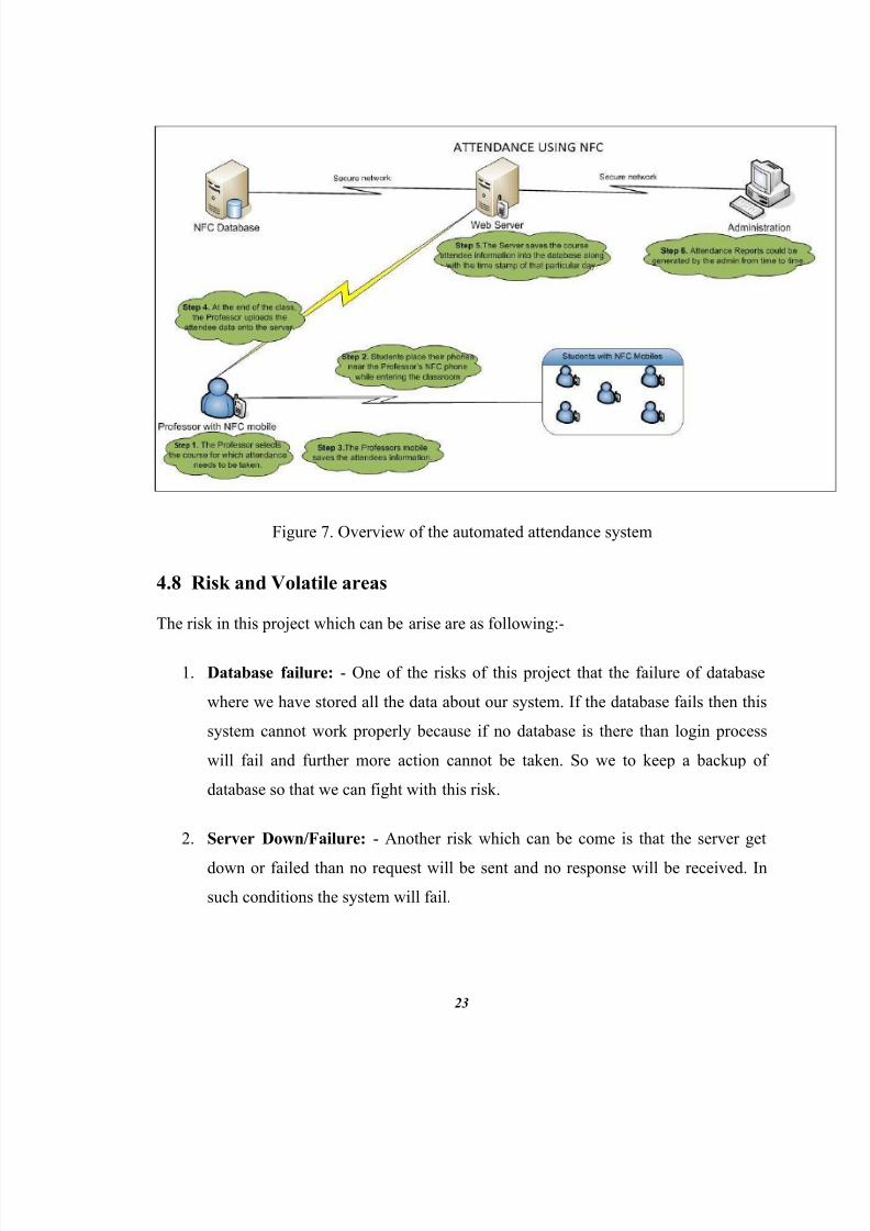
Figure 8 shows the proposed system architecture. The basic architecture of this system is

that when student shows his NFC tag to the NFC scanner at that time data is matchedfrom the database and if the data are correct then student gets entry in the class and his

attendance is counted and database is updated instantly. The main actors are

management, teachers and students. Student has to touch his tag to record his attendance.

Teacher can cross check attendances which have been registered on the day while

management can add and delete the NFC tags and can check the attendance status.

5.1 Overview

This system is an android application for daily attendance system in schools, colleges,

and institutions of students which uses NFC technology. It has a unique identification

NFC tag of a student by using that he can register his attendance. This application also

provide the facility of cross checking the attendances which have been made on the day.

It also facilitate parents and students to check their attendances of the day and month as

well and percentages of attendances. It generates the list of debarred students

automatically on the basis of their attendance percentages.

8/10/2019 SRS NFC Based Attendance System(2)

http://slidepdf.com/reader/full/srs-nfc-based-attendance-system2 33/56

26

Figure 8. Flow schema of the system

5.2 Modules

The modules of this system are as following:-

Login: - This is the login interface in which admin has to login himself first of all

so that he can access the further options. Every authentic user has a username and

password to login in the system.

The supplementary tool Attendance Status Tracker also has login interface. In

that application teacher, student and parents can also login. Everyone is provided

8/10/2019 SRS NFC Based Attendance System(2)

http://slidepdf.com/reader/full/srs-nfc-based-attendance-system2 34/56

27

with his unique username and password to get access of application by

management. After login further more action can be done.

Choice: - Choice is the second interface of this system in which some choices are provided for admin. After logging in admin has to choose one of them like check

attendance status, add a new tag, delete a tag or record attendance of students.

In the supplementary tool the only choice which is given to students and parents is

to check the attendance status while teacher can also check the attendance status

of the whole class.

Record Attendance: - This interface is the main interface of the system in whicha student can register his attendance by simply touching his NFC tag with the

system. In the beginning of day admin login and open this interface after that a

student can make his attendance.

Add/Delete tags: - This is the interface in which admin can delete and add a new

NFC tag. This option is available only for management.

Attendance status Class/Student: - In this interface admin can check theattendance status of whole class as well as particular student that who is present

and not on any day.

This interface is also available in Attendance Status Tracker application for

parents, students and teachers. Student and parent can only check their

attendances while teacher can also check the attendances of whole class.

8/10/2019 SRS NFC Based Attendance System(2)

http://slidepdf.com/reader/full/srs-nfc-based-attendance-system2 35/56

28

6. UML diagrams

The Unified Modeling Language (UML) is a general-purpose modeling language in the

field of software engineering, which is designed to provide a standard way to visualize

the design of a system. The UML diagrams of this project are as following:-

6.1 Requirement Paragraph

Make an android application for daily attendance system in schools, colleges, and

institutions for students which uses NFC technology. There should be a unique

identification NFC tag of a student by using that he can register his attendance. To make

attendance of any student it is very necessary that first of all the admin must login. This

application should also provide the facility of cross checking the attendances which have

been made on the day, to the teacher. It also facilitate the parents and students to check

their attendances of the any day and month as well and percentages of attendances. It

should generate the list of debarred students automatically on the basis of their attendance

percentages. Admin can also add new students and can delete old students in database.

6.2 Noun Phrase Analysis

After analyzing the requirement paragraph we can see that there are following nouns:-

1. Android application

2. Daily attendance system

3. Institutions

4. Student

5. NFC technology

6. NFC Tag

8/10/2019 SRS NFC Based Attendance System(2)

http://slidepdf.com/reader/full/srs-nfc-based-attendance-system2 36/56

29

7. Attendance

8. Admin

9. Parents

10. Database

From the upper list of nouns we can easily say that users of this system are:-

1. Admin

2. Student

3. Parent

List of verbs which can be find out from the paragraph are:-

1. Login

2. Cross checking of attendances

3. Check attendance status

4. Generate the list of debarred students

5. Add new student/tag

6. Delete old student/tag

8/10/2019 SRS NFC Based Attendance System(2)

http://slidepdf.com/reader/full/srs-nfc-based-attendance-system2 37/56

30

6.3 Use Case Diagram

A use case diagram at its simplest is a representation of a user's interaction with the

system and depicting the specifications of a use case. A use case diagram can portray thedifferent types of users of a system and the various ways that they interact with the

system. This type of diagram is typically used in conjunction with the textual use

case and will often be accompanied by other types of diagrams as well. The use case

diagram of this NFC based attendance system is as following:-

Figure 9. Use case diagram of system

8/10/2019 SRS NFC Based Attendance System(2)

http://slidepdf.com/reader/full/srs-nfc-based-attendance-system2 38/56

31

6.4 Sequence Diagram

A Sequence diagram is an interaction diagram that shows how processes operate with

one another and in what order. It is a construct of a Message Sequence Chart . A sequencediagram shows object interactions arranged in time sequence. It depicts the objects and

classes involved in the scenario and the sequence of messages exchanged between the

objects needed to carry out the functionality of the scenario. Sequence diagrams are

typically associated with use case realizations in the Logical View of the system under

development. Sequence diagrams are sometimes called event diagrams or event

scenarios . Sequence diagram for this project is as following:-

8/10/2019 SRS NFC Based Attendance System(2)

http://slidepdf.com/reader/full/srs-nfc-based-attendance-system2 39/56

32

Figure 10. Sequence Diagram

8/10/2019 SRS NFC Based Attendance System(2)

http://slidepdf.com/reader/full/srs-nfc-based-attendance-system2 40/56

33

6.5 Data Flow Diagram

A data flow diagram (DFD ) is a graphical representation of the "flow" of data through

an information system, modeling its process aspects. A DFD is often used as a preliminary step to create an overview of the system, which can later be elaborated. DFDscan also be used for the visualization of data processing (structured design).

A DFD shows what kind of information will be input to and output from the system,where the data will come from and go to, and where the data will be stored. It does notshow information about the timing of processes, or information about whether processeswill operate in sequence or in parallel (which is shown on a flowchart). Data FlowDiagram for this system is as following:-

Figure 11. 0 Level DFD

8/10/2019 SRS NFC Based Attendance System(2)

http://slidepdf.com/reader/full/srs-nfc-based-attendance-system2 41/56

34

1 Level DFD: -

Figure 12. 1 Level DFD

8/10/2019 SRS NFC Based Attendance System(2)

http://slidepdf.com/reader/full/srs-nfc-based-attendance-system2 42/56

35

6.6 Activity Diagram

Activity diagrams are graphical representations of workflows of stepwise activities and

actions with support for choice, iteration and concurrency. In the Unified ModelingLanguage , activity diagrams are intended to model both computational and organizational

processes (i.e. workflows). Activity diagrams show the overall flow of control. Various

activity diagrams for this system are as following:-

Figure 13. Activity diagram for updation of student record

8/10/2019 SRS NFC Based Attendance System(2)

http://slidepdf.com/reader/full/srs-nfc-based-attendance-system2 43/56

36

Figure 14. Activity diagram for attendance status

8/10/2019 SRS NFC Based Attendance System(2)

http://slidepdf.com/reader/full/srs-nfc-based-attendance-system2 44/56

37

Figure 15. Activity diagram for recording attendance

8/10/2019 SRS NFC Based Attendance System(2)

http://slidepdf.com/reader/full/srs-nfc-based-attendance-system2 45/56

38

6.7 Collaboration Diagram

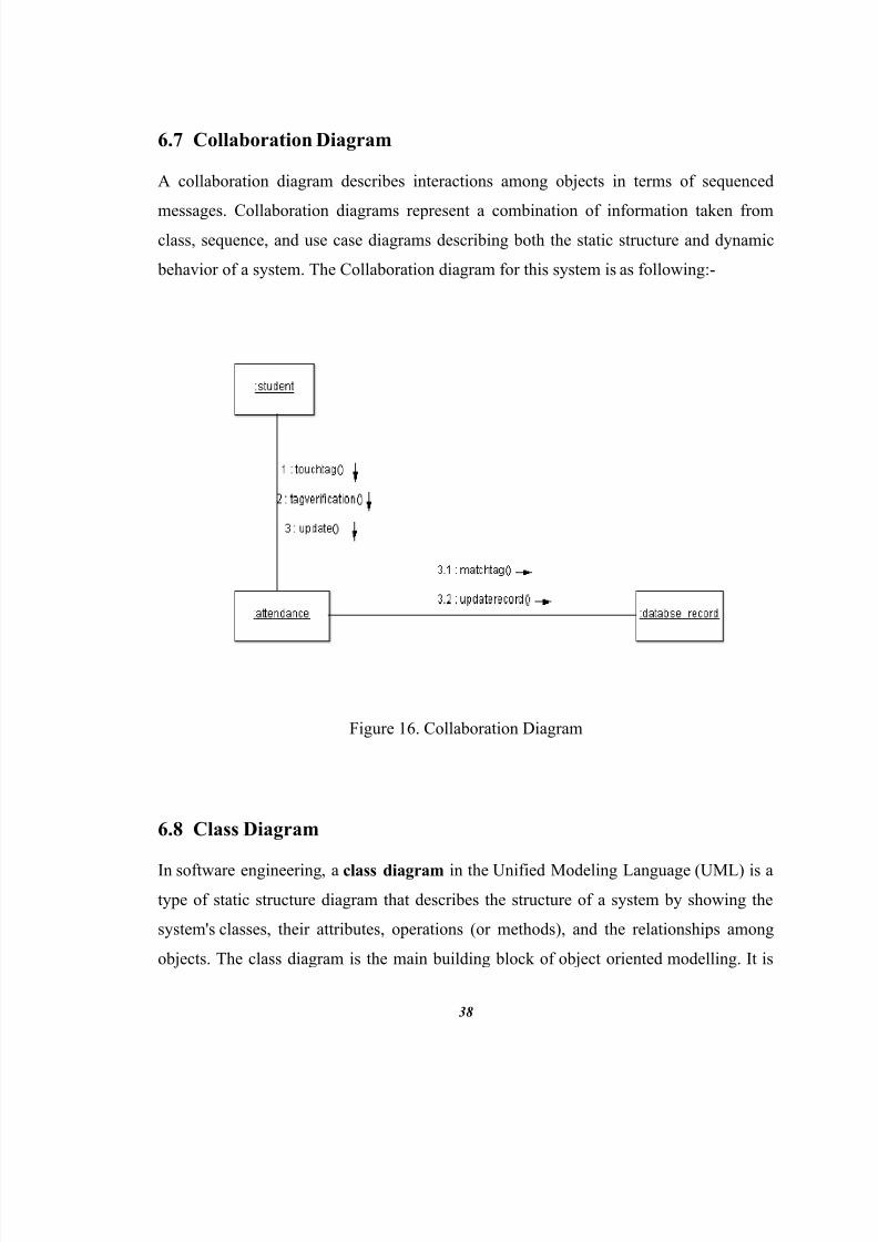
A collaboration diagram describes interactions among objects in terms of sequenced

messages. Collaboration diagrams represent a combination of information taken fromclass, sequence, and use case diagrams describing both the static structure and dynamic

behavior of a system. The Collaboration diagram for this system is as following:-

Figure 16. Collaboration Diagram

6.8 Class Diagram

In software engineering , a class diagram in the Unified Modeling Language (UML) is atype of static structure diagram that describes the structure of a system by showing the

system's classes , their attributes, operations (or methods), and the relationships among

objects. The class diagram is the main building block of object oriented modelling. It is

8/10/2019 SRS NFC Based Attendance System(2)

http://slidepdf.com/reader/full/srs-nfc-based-attendance-system2 46/56

39

used both for general conceptual modelling of the systematics of the application, and for

detailed modelling translating the models into programming code . Class diagrams can

also be used for data modeling . The classes in a class diagram represent both the main

objects, interactions in the application and the classes to be programmed.

Figure 17. Class Diagram

6.9 Class-responsibility-collaboration card

Class-responsibility-collaboration (CRC ) cards are a brainstorming tool used in thedesign of object-oriented software. They were originally proposed by Ward Cunningham and Kent Beck as a teaching tool, but are also popular among expert designers andrecommended by extreme programming supporters. Martin Fowler has described CRC

8/10/2019 SRS NFC Based Attendance System(2)

http://slidepdf.com/reader/full/srs-nfc-based-attendance-system2 47/56

40

cards as a viable alternative to UML sequence diagram to design the dynamics of objectinteraction and collaboration

CRC cards are usually created from index cards. Members of a brainstorming session willwrite up one CRC card for each relevant class/object of their design. The card is

partitioned into three areas:

1. On top of the card, the class name2. On the left, the responsibilities of the class3. On the right, collaborators (other classes) with which this class interacts to fulfill

its responsibilities

Using a small card keeps the complexity of the design at a minimum. It focuses thedesigner on the essentials of the class and prevents her/him from getting into its detailsand inner workings at a time when such detail is probably counter-productive. It alsoforces the designer to refrain from giving the class too many responsibilities. Because thecards are portable, they can easily be laid out on a table and re-arranged while discussinga design with other people.

Figure 18. CRC for Admin

8/10/2019 SRS NFC Based Attendance System(2)

http://slidepdf.com/reader/full/srs-nfc-based-attendance-system2 48/56

41

Figure 19. CRC for student

Figure 20. CRC for nfc_scanner

8/10/2019 SRS NFC Based Attendance System(2)

http://slidepdf.com/reader/full/srs-nfc-based-attendance-system2 49/56

42

6.10 E-R Diagram

In software engineering , an entity – relationship model (ER model ) is a data model for

describing the data or information aspects of a business domain or its processrequirements, in an abstract way that lends itself to ultimately being implemented in

a database such as a relational database . The main components of ER models

are entities (things) and the relationships that can exist among them, and databases. The

Entity – Relationship diagram for this system is as below:-

Figure 21. E-R Diagram

8/10/2019 SRS NFC Based Attendance System(2)

http://slidepdf.com/reader/full/srs-nfc-based-attendance-system2 50/56

43

7. Database Schema

7.1 Tables, Fields and Relationships

In this project to store data we have made following tables:-

1. Admin table: -

This table is used to store the data of the admins of the system. This table has

three fields username, password and name. Whenever an admin login to the

system then his details are matched from this table. If the details are matched then

he get access. The detailed schema of the table is as following:-

Table 3. Admin Table

2. Parent: -

This is the second table of our project in which we have stored the details of the

parents of the students like their names, mobile number, username, and password.

When a parent login to the supplementary application Attendance Status Tracker

then his details are matched from this table. If the details are matched then he get

access s o that he can check his ward’s attendances. The detailed schema of the

table is as following:-

Field-Name DataType Allows Null Default Value Extra

Username varchar(50) No none PRIMARY KEY

Password varchar(50) No none

Name varchar(70) No none

8/10/2019 SRS NFC Based Attendance System(2)

http://slidepdf.com/reader/full/srs-nfc-based-attendance-system2 51/56

44

Field-Name DataType Allows Null

DefaultValue

Extra

parent_id int(11) No none AUTO_INCREMENT

& PRIMARY KEY

parent_name varchar(50) No none

username varchar(30) No none

password varchar(30) No none

Mobile varchar(11) No none

Table 4. Parent Table

3. Relation: -

This is the third table of our project which contains the information of relation

between student and parent. In this table we have kept the record of parent_id and

student_id. When a parent wants to check his child’s attendance status

automatically server responses to him according to this table. The detailed schema

of the table is as following:-

Table 5. Relation Table

4. Student_attendance: -

This table is the main table of this system because it contains the information of

attendances of various student’s like on which date and time who was pr esent in

the class. This table has three fields student_id, date, and time. The detailed

schema of the table is as following:-

Field-Name DataType Allows Null Default Value

parent_id int(11) No none

student_id varchar(11) No none

8/10/2019 SRS NFC Based Attendance System(2)

http://slidepdf.com/reader/full/srs-nfc-based-attendance-system2 52/56

45

Table 6. Attendance Table

5. Student_info: -

This table contains the all information about student like his name, branch, sem,

tag associated with him, student_id, username, password etc. The detailed schema

is as following:-

Table 7. Student Table

Databases: -

In our project we are using MySQL database for storing our data. The data will be on

server which is Apache 2.

Field-Name DataType Allows Null Default Value Extra

Student_id varchar(11) No none PRIMARY KEY

Date date No none

Time time No none

Field-Name DataType Allows Null Default Value Extra

Student_id varchar(11) No none PRIMARY KEY

Name varchar(70) No none

Username varchar(30) No none

Password varchar(30) No None

Class varchar(30) No NoneBranch varchar(50) No None

Sem int(1) No none

Gender varchar(1) No None

Cotact_number varchar(11) No None

Rfid Varchar(16) No None

8/10/2019 SRS NFC Based Attendance System(2)

http://slidepdf.com/reader/full/srs-nfc-based-attendance-system2 53/56

46

8. Cost Estimation

After reading all the requirements, layouts and functions of this proposed system the cost

can be estimated on the basis of following points and COCOMO model.

1. Android based NFC Scanner is required.

2. NFC tags are required.

3. As the system is for colleges and institutions so the database will be large so a

good database management is required.

The basic COCOMO equations take the form:-

Effort Applied (E) = a b(SLOC) b b [ person-months ]

Development Time (D) = c b(Effort Applied) d b [months]

People required (P) = Effort Applied / Development Time [count]

where, SLOC is the estimated number of delivered lines (expressed in thousands ) ofcode for project. The coefficients ab, bb, cb and d b are given in the following table:

Software project a b b b c b d b

Organic 2.4 1.05 2.5 0.38

Semi-detached 3.0 1.12 2.5 0.35

Embedded 3.6 1.20 2.5 0.32

Table 8. Values of variables in COCOMO Model

8/10/2019 SRS NFC Based Attendance System(2)

http://slidepdf.com/reader/full/srs-nfc-based-attendance-system2 54/56

47

Now in our project the no of effective source line of code (SLOC) is 1740 (includes only

data declaration statements and executable statements) and the amount payble to the

person working on the project per month is $100 ( ₹6153.00 ). So according to the

COCOMO Model the estimated cost is:-

Software Development (Elaboration and Construction)

Effort = 7.3 Person-monthsSchedule = 7.1 MonthsCost = $725 ( ₹44609.24 )

Total Equivalent Size = 1740 SLOC

Acquisition Phase Distribution

Phase Effort (Person-months) Schedule (Months) Average Staf Cost (Dollars)Inception 0.4 0.9 0.5 $44Elaboration 1.7 2.6 0.7 $174Construction 5.5 4.4 1.2 $551Transition 0.9 0.9 1.0 $87

Table 9. Acquisition Phase Distribution

Software Effort Distribution for RUP/MBASE (Person-Months)

Phase/Activity Inception Elaboration Construction TransitionManagement 0.1 0.2 0.6 0.1Environment/CM 0.0 0.1 0.3 0.0Requirements 0.2 0.3 0.4 0.0Design 0.1 0.6 0.9 0.0Implementation 0.0 0.2 1.9 0.2Assessment 0.0 0.2 1.3 0.2Deployment 0.0 0.1 0.2 0.3

Table 10. Software Effort Distribution

8/10/2019 SRS NFC Based Attendance System(2)

http://slidepdf.com/reader/full/srs-nfc-based-attendance-system2 55/56

8/10/2019 SRS NFC Based Attendance System(2)

http://slidepdf.com/reader/full/srs-nfc-based-attendance-system2 56/56

10. Appendix B: References

1. Silberschatz,Korth,Sudarshan “Database System Concepts”:5thEd. New

York:McGraw-Hill(May 2006)

2. Grady Booch,James Rambaugh,Ivar Jacobson “Unified Modeling Language User

Guide” :1stEd. Addition Wesley(April 1998)

3. SAM S“Teach yourself UML in 24 hours”:4thEd.USA (March 2004).

4. Thomas B. Valesky “Enterprise JavaBeans(TM): Developing Component -Based

Distributed Applications” ISBN -13: 978-0201604467, Addison-Wesley

Professional (May 1999).

5. Roger S. Pressman “Software Engineering: A Practitioner’s Approach” :7th Ed.

Singapore: McGraw-Hill(July2010) pp 841-861.

6. http://en.wikipedia.org/wiki/NFC


Recommended